EP2685646B1 - Verfahren zur unterstützung einer dynamic-time-division-duplex (d-tdd)-downlink-uplink-konfiguration in einem drahtlosen kommunikationssystem und vorrichtung dafür - Google Patents
Verfahren zur unterstützung einer dynamic-time-division-duplex (d-tdd)-downlink-uplink-konfiguration in einem drahtlosen kommunikationssystem und vorrichtung dafür Download PDFInfo
- Publication number
- EP2685646B1 EP2685646B1 EP12752258.9A EP12752258A EP2685646B1 EP 2685646 B1 EP2685646 B1 EP 2685646B1 EP 12752258 A EP12752258 A EP 12752258A EP 2685646 B1 EP2685646 B1 EP 2685646B1
- Authority
- EP
- European Patent Office
- Prior art keywords
- downlink
- uplink
- tdd
- subframe
- tdd downlink
- Prior art date
- Legal status (The legal status is an assumption and is not a legal conclusion. Google has not performed a legal analysis and makes no representation as to the accuracy of the status listed.)
- Not-in-force
Links
Images


Classifications
-
- H—ELECTRICITY
- H04—ELECTRIC COMMUNICATION TECHNIQUE
- H04J—MULTIPLEX COMMUNICATION
- H04J3/00—Time-division multiplex systems
- H04J3/16—Time-division multiplex systems in which the time allocation to individual channels within a transmission cycle is variable, e.g. to accommodate varying complexity of signals, to vary number of channels transmitted
- H04J3/1694—Allocation of channels in TDM/TDMA networks, e.g. distributed multiplexers
-
- H—ELECTRICITY
- H04—ELECTRIC COMMUNICATION TECHNIQUE
- H04B—TRANSMISSION
- H04B7/00—Radio transmission systems, i.e. using radiation field
- H04B7/24—Radio transmission systems, i.e. using radiation field for communication between two or more posts
- H04B7/26—Radio transmission systems, i.e. using radiation field for communication between two or more posts at least one of which is mobile
- H04B7/2643—Radio transmission systems, i.e. using radiation field for communication between two or more posts at least one of which is mobile using time-division multiple access [TDMA]
-
- H—ELECTRICITY
- H04—ELECTRIC COMMUNICATION TECHNIQUE
- H04L—TRANSMISSION OF DIGITAL INFORMATION, e.g. TELEGRAPHIC COMMUNICATION
- H04L5/00—Arrangements affording multiple use of the transmission path
- H04L5/14—Two-way operation using the same type of signal, i.e. duplex
-
- H—ELECTRICITY
- H04—ELECTRIC COMMUNICATION TECHNIQUE
- H04W—WIRELESS COMMUNICATION NETWORKS
- H04W72/00—Local resource management
- H04W72/12—Wireless traffic scheduling
- H04W72/1263—Mapping of traffic onto schedule, e.g. scheduled allocation or multiplexing of flows
Definitions
- the present invention relates to wireless communication, and more particularly, to a method and apparatus for supporting dynamic-time division duplex (D-TDD) downlink-uplink configuration in a wireless communication system.
- D-TDD dynamic-time division duplex
- CDMA code division multiple access
- FDMA frequency division multiple access
- TDMA time division multiple access
- OFDMA orthogonal frequency division multiple access
- SC-FDMA single carrier frequency division multiple access
- CDMA may be embodied by radio technology such as universal terrestrial radio access (UTRA) or CDMA2000.
- TDMA may be embodied by radio technology such as global system for mobile communications (GSM)/general packet radio service (GPRS)/enhanced data rates for GSM evolution (EDGE).
- GSM global system for mobile communications
- GPRS general packet radio service
- EDGE enhanced data rates for GSM evolution
- OFDMA may be embodied by radio technology such as IEEE 802.11 (Wi-FiTM), IEEE 802.16 (WiMAX), IEEE 802-20, evolved UTRA (E-UTRA), etc.
- UTRA is a part of universal mobile telecommunications system (UMTS).
- 3rd generation partnership project (3GPP) long-term evolution (LTE) is a part of evolved UMTS (E-UMTS) using E-UTRA and employs OFDMA in downlink and SC-FDMA in uplink.
- LTE-advanced (LTE-A) is an evolved version of 3GPP LTE.
- Document WO 2010/061053 A1 may be construed to disclose techniques to select compatible TDD frame structure pairs for a base station and a relay node; designate a number of certain subframes in each of the selected frame structure pairs to be multimedia broadcast multicast service single frequency network subframes; and using the selected frame structure pairs, perform communications between the base station and a relay node-attached user equipment, while performing backhauling during the certain subframes.
- techniques select compatible TDD frame structure pairs for a base station and a relay node that establishes operation with selected subframe pairs on a relay link, signal a blank subframe configuration for a relay node-attached user equipment corresponding to the selected subframe pairs, and, using the selected subframe pairs, perform communications between the base station and the relay node-attached user equipment, while performing black hauling during the selected subframe pairs signaled as blank subframes to the user equipment.
- An object of the present invention devised to solve the problem lies in a method of supporting dynamic-time division duplex (D-TDD) downlink-uplink configuration by a first network node in a wireless communication system.
- D-TDD dynamic-time division duplex
- Another object of the present invention devised to solve the problem lies in a first network node apparatus for supporting D-TDD downlink-uplink configuration in a wireless communication system.
- a method of supporting dynamic-time division duplex (D-TDD) downlink-uplink configuration by a first network node in a wireless communication system including setting a TDD downlink-uplink configuration set by selecting two or more TDD downlink-uplink configurations according to a predetermined rule among a plurality of predefined TDD downlink-uplink configurations, wherein, according to the predetermined rule, the two or more TDD downlink-uplink configurations are selected corresponding to number of subframes having different subframe type per subframe index from the plurality of the TDD downlink-uplink configurations.
- the types of the subframes preferably include a downlink subframe, an uplink subframe, and a special subframe.
- the method preferably further includes transmitting information on the set TDD downlink-uplink configuration set to a second network node.
- the number preferably includes at least 1, 1.5, 2, 2.5, 3.5, 4, 4.5, or 5.5.
- the setting of the TDD downlink-uplink configuration set preferably includes setting a TDD downlink-uplink configuration in further consideration of number of single frequency network (SFN) support subframes.
- SFN single frequency network
- a method of supporting dynamic-time division duplex (D-TDD) downlink-uplink configuration by a first network node in a wireless communication system including setting a TDD downlink-uplink configuration set by selecting two or more TDD downlink-uplink configurations according to a predetermined rule among a plurality of predefined TDD downlink-uplink configurations, wherein, according to the predetermined rule, the two or more TDD downlink-uplink configurations are selected based on the number of subframes corresponding to all downlink sections from a single frequency network (SFN) support subframe index and remaining subframes except for a MBSFN subframe.
- the SFN subframe index preferably includes at least 3, 4, 8, or 9.
- the number preferably includes at least 1, 2, or 4.
- the method preferably further includes transmitting information of the set TDD downlink-uplink configuration set to a second network node.
- the first network node preferably is a multi-cell/multicast coordination entity (MCE) and the second network node preferably is a base station.
- MCE multi-cell/multicast coordination entity
- a first network node for supporting dynamic-time division duplex (D-TDD) downlink-uplink configuration in a wireless communication system
- the first network including a processor for setting a TDD downlink-uplink configuration set by selecting two or more TDD downlink-uplink configurations according to a predetermined rule among a plurality of predefined TDD downlink-uplink configurations, wherein, according to the predetermined rule, the two or more TDD downlink-uplink configurations corresponding to number of subframes having different subframe type per subframe index are selected from the plurality of the TDD downlink-uplink configurations.
- D-TDD dynamic-time division duplex
- a first network node for supporting dynamic-time division duplex (D-TDD) downlink-uplink configuration in a wireless communication system
- the first network node including a processor for setting a TDD downlink-uplink configuration set by selecting two or more TDD downlink-uplink configurations among a plurality of predefined TDD downlink-uplink configurations, wherein the TDD downlink-uplink configuration set includes two or more TDD downlink-uplink configurations set based on the number of subframes corresponding to all downlink sections from a single frequency network (SFN) support subframe index and remaining subframes except for a MBSFN subframe.
- the first network node preferably further includes a transmitter for transmitting information on the set TDD downlink-uplink configuration set to a second network node.
- the information of the set TDD downlink-uplink configuration set preferably is transmitted via an M2 interface.
- performance of an overall communication system may be improved by overcoming problems such as interference between cells, which may arise during D-TDD support in a conventional system.
- a user equipment refers to any mobile or fixed type device of a user side, such as a user equipment, a mobile station (MS), an advanced mobile station (AMS), etc.
- a base station refers to any node of a network side that communicates with the UE, such as a Node B, an eNode B, a base station, access point (AP), etc.
- the BS may include a cell, a sector, etc.
- a UE may receive information from a BS in downlink and transmit information in uplink.
- the information transmitted or received by the UE may be data and various control information.
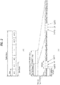
- FIG. 1 is a block diagram illustrating configuration of a base station (BS) 105 and a user equipment (UE) 110 in a wireless communication system 100.
- BS base station
- UE user equipment
- the wireless communication system 100 For simplification of the wireless communication system 100, one base station 105 and one UE 110 are illustrated. However, the wireless communication system 100 may include one or more BSs and/or UEs.
- the BS 105 may include a transmit (Tx) data processor 115, a symbol modulator 120, a transmitter 125, a transceiving antenna 130, a processor 180, a memory 185, a receiver 190, a symbol demodulator 195, and a receive (Rx) data processor 197.
- the UE 110 may include a transmit (Tx) data processor 165, a symbol modulator 170, a transmitter 175, a transceiving antenna 135, a processor 155, a memory 160, a receiver 140, a symbol demodulator 145, and a receive (Rx) data processor 150.
- the BS 105 and the UE 110 each include a plurality of transceiving antennas.
- the BS 105 and the UE 110 according to the present invention support a multiple input multiple output (MIMO) system.
- the BS 105 according to the present invention may support both single user-MIMO (SU-MIMO) and multi user-MIMO (MU-MIMO).
- SU-MIMO single user-MIMO
- MU-MIMO multi user-MIMO
- the Tx data processor 115 receives traffic data, formats and codes the received traffic data, and interleaves and modulates (or symbol-maps) the coded traffic data to provide modulated symbols ("data symbols").
- the symbol modulator 120 receives and processes the data symbols and pilot symbols to provide a stream of the symbols.
- the symbol modulator 120 multiplexes the data and pilot symbols and transmits the multiplexed data and pilot symbols to the transmitter 125.
- each of the transmitted symbols may be a data symbol, a pilot symbol, or a signal value of zero.
- pilot symbols may be consecutively transmitted.
- the pilot symbols may be frequency division multiplexed (FDM), orthogonal frequency division multiplexed (OFDM), time division multiplexed (TDM), or code division multiplexed (CDM) symbols.
- the transmitter 125 receives the stream of the symbols and converts the stream into one or more analog signals. In addition, the transmitter 125 further adjusts (e.g., amplifies, filters, and frequency-upconverts) the analog signals to generate a downlink signal suitable for transmission through a radio channel. Then, the transceiving antenna 130 transmits the generated downlink signal to the UE 110.
- the transmitter 125 adjusts (e.g., amplifies, filters, and frequency-upconverts) the analog signals to generate a downlink signal suitable for transmission through a radio channel. Then, the transceiving antenna 130 transmits the generated downlink signal to the UE 110.
- the transceiving antenna 135 receives the downlink signal from the BS 105 and provides the received signal to the receiver 140.
- the receiver 140 adjusts (e.g., filters, amplifies, and frequency-downconverts) the received signal, and digitizes the adjusted signal to acquire samples.
- the symbol demodulator 145 demodulates the received pilot symbols and provides the pilot symbols to the processor 155 for channel estimation.
- the symbol demodulator 145 receives a frequency response estimated value for downlink from the processor 155, performs data demodulation on the received data symbols to obtain a data symbol estimated value (which corresponds to estimated values of transmitted data symbols), and provides the data symbol estimated value to the Rx data processor 150.
- the Rx data processor 150 demodulates (that is, symbol-demaps) the data symbol estimated values, and deinterleaves and decodes the data symbol estimated values to restore transmitted traffic data.
- Processing by the symbol demodulator 145 and the Rx data processor 150 is auxiliary to processing by the symbol modulator 120 and the Tx data processor 115 in the BS 105, respectively.
- the Tx data processor 165 processes traffic data to provide data symbols.
- the symbol modulator 170 may receive the data symbols and multiplex and demodulate the data symbols to provide a stream of the symbols to the transmitter 175.
- the transmitter 175 receives and processes the stream of the symbols to generate an uplink signal.
- the transceiving antenna 135 transmits the generated uplink signal to the BS 105.
- the uplink signal is received from the UE 110 through the transceiving antenna 130, and the receiver 190 acquires samples obtained by processing the received uplink signal. Then, the symbol demodulator 195 processes the samples to provide pilot symbols and a data symbol estimated value, which are received for uplink. The Rx data processor 197 processes the data symbol estimated value to restore the traffic data transmitted from the UE 110.
- the processors 155 and 180 of the UE 110 and the BS 105 order (e.g., control, adjust, manage, etc.) operations in the UE 110 and the BS 105, respectively.
- the processors 155 and 180 may be respectively connected to the memories 160 and 185 that store program code and data.
- the memories 160 and 185 are connected to the processor 180 and store an operating system, application, and general files.
- the processors 155 and 180 may also be called a controller, a microcontroller, a microprocessor, a microcomputer, etc.
- the processors 155 and 180 may be embodied by hardware, firmware, software, or a combination thereof.
- the processors 155 and 180 may include application specific integrated circuits (ASICs), digital signal processors (DSPs), digital signal processing devices (DSPDs), programmable logic devices (PLDs), field programmable gate arrays (FPGAs), etc. which are configured to implement the present invention.
- ASICs application specific integrated circuits
- DSPs digital signal processors
- DSPDs digital signal processing devices
- PLDs programmable logic devices
- FPGAs field programmable gate arrays
- firmware or the software may be configured to contain a module, process, or function used to perform functions or operations according to the present invention.
- the firmware or software configured to implement the present invention may be included in the processors 155 and 180 or may be stored in the memories 160 and 185 and driven by the processors 155 and 180.
- Layers of a wireless interface protocol between a UE and a wireless communication system (network) and between a BS and the system may be classified into a first layer L1, a second layer L2, and a third layer L3 based on the three lower layers of the open systems interconnection (OSI) model that is well known in the field of communications.
- a physical layer belongs to the first layer L1 and provides an information transmission service through a physical channel.
- a radio resource control (RRC) layer belongs to the third layer and provides control radio resources between the UE and the network. The UE and the base station may exchange RRC messages through the wireless communication network and the RRC layer.
- FIG. 2(A) illustrates a structure of a radio frame used in a 3GPP LTE system as an example of a wireless communication system.
- one radio frame has a length of 10 ms (327200 ⁇ Ts) and includes ten subframes of equal size.
- Each subframe has a length of 1 ms and includes two slots.
- Each slot has a length of 0.5 ms (15360 ⁇ T s ).
- the slot includes a plurality of OFDM symbols or single carrier-frequency division multiple access (SC-FDMA) symbols in a time domain and a plurality of resource blocks (RBs) in a frequency domain.
- SC-FDMA single carrier-frequency division multiple access
- one resource block includes twelve subcarriers x seven (or six) OFDM symbols or SC-FDMA symbols.
- a transmission time interval (TTI) which is a data transmission time unit, may be determined in a unit of one or more subframes.
- TTI transmission time interval
- the aforementioned structure of the radio frame is merely an example, and various modifications may be made in the number of subframes included in the radio frame, the number of slots included in the subframe, or the number of OFDM symbols or SC-FDMA symbols included in the slot.
- FIG. 2(B) illustrates a frame structure type 2 of 3GPP LTE as an example of a wireless communication system.
- the frame structure type 2 is applied to time division duplex (TDD).
- TDD time division duplex
- one radio frame has a length of 10 ms (327200 ⁇ Ts) and includes ten subframes of equal size.
- Each subframe has a length of 1 ms and includes two slots.
- Each slot has a length of 0.5 ms (15360 ⁇ Ts).
- Each half-frame includes five subframes.
- D denotes a subframe reserved for downlink transmission
- U denotes a subframe reserved for uplink transmission
- S denotes a special subframe including a downlink pilot time slot (DwPTS), a guard period (GP), and an uplink pilot time slot (UpPTS).
- DwPTS is used for initial cell search, synchronization, or channel estimation by a UE.
- UpPTS is used for channel estimation by a BS and uplink transmission synchronization in a UE.
- GP is a period for removal of interference generated in uplink due to multipath delay of a downlink signal between uplink and downlink.
- the special subframe S exists in all half-frames. In case of 5 ms downlink-to-uplink switch-point periodicity, the special subframe S exists in a first half-frame only. Subframes # 0 and 5 (subframes 0 and 5) and DwPTS are always reserved for downlink transmission. A subframe immediately subsequent to UpPTS and the special subframe are always reserved for uplink transmission. When multiple cells are aggregated, the UE assumes the same uplink-downlink configuration across all the cells and that GPs of special subframes in different cells have an overlap of at least 1456 ⁇ Ts.
- the aforementioned structure of the radio frame is merely an example and various modifications may be made in the number of subframes included in the radio frame, the number of slots included in the subframe, or the number of symbols included in the slot.
- Table 1 below shows special subframe configuration (length of DwPTS/GP/UpPTS).
- Table 1 shows special subframe configuration (length of DwPTS/GP/UpPTS).
- Table 1 shows special subframe configuration Normal cyclic prefix in downlink Extended cyclic prefix in downlink DwPTS UpPTS
- Table 2 below shows uplink-downlink configuration.
- Uplink-downlink configuration Downlink-to-Uplink Switch-point periodicity Subframe number 0 1 2 3 4 5 6 7 8 9 0 5 ms D S U U U D S U U U 1 5 ms D S U U D D S U U D 2 5 ms D S U D D D S U D D 3 10 ms D S U U U D D D D D D 4 10 ms D S U U D D D D D D 5 10 ms D S U D D D D D D D D D 6 5 ms D S U U U U D S U U U D S U U D
- a frame structure type 2 of 3GPP LTE system has seven uplink-downlink configurations. According to configurations, the position or number of a downlink subframe, a special frame, and an uplink subframe may be differently configured.
- various embodiments of the present invention will be described in terms of uplink-downlink configurations of the frame structure type 2 shown in Table 2 above.
- FIGS. 3 are diagrams illustrating a downlink subframe structure and an uplink subframe structure in a 3GPP LTE as an example of a mobile communication system.
- one downlink subframe includes two slots in a time domain.
- a maximum of 3 OFDM symbols located in a front part of a first slot of a downlink subframe correspond to a control region to which control channels are allocated.
- the remaining OFDM symbols correspond to a data region to which a physical downlink shared channel (PDSCH) is allocated.
- PDSCH physical downlink shared channel
- the downlink control channels used in a 3GPP LTE system, etc. may include a physical control format indicator channel (PCFICH), a physical downlink control channel (PDCCH), or a physical hybrid-ARQ indicator channel (PHICH).
- PCFICH physical control format indicator channel
- PDCCH physical downlink control channel
- PHICH physical hybrid-ARQ indicator channel
- the PCFICH transmitted in a first OFDM symbol of a subframe carries information regarding the number (that is, an area of the control region) of OFDM symbols used for transmission of control channels within a subframe.
- the control information transmitted through the PDCCH is referred to as downlink control information (DCI).
- DCI refers to uplink resource allocation information, downlink resource allocation information, uplink transmit power control command to arbitrary UE groups, etc.
- the PHICH carries acknowledgement (ACK)/ negative acknowledgement (NACK) signals as a response to uplink hybrid automatic repeat request (HARQ). That is, the ACK/NACK signals as a response to the uplink data transmitted from a UE are transmitted on the PHICH.
- ACK acknowledgement
- NACK negative acknowledgement
- the PDCCH as a downlink physical channel will be described.
- a BS may transmit resource allocation and transmission format of PDSCH (which are also referred to as DL grant), resource allocation information of PUSCH (which is also referred to as UL grant), an aggregate set of a transmit power control (TPC) command of an arbitrary UE and individual UEs in a group, and activation of voice over Internet protocol (VoIP) through the PDCCH.
- the BS may transmit a plurality of PDCCHs in the control region and the UE may monitor the plural PDCCHs.
- the PDCCH includes an aggregate of one or more contiguous control channel elements (CCEs).
- the BS may transmit the PDCCH including the aggregate of one or more contiguous CCEs through subblock interleaving and then transmit the PDCCH through the control region.
- CCEs contiguous control channel elements
- the CCE is a logical allocation unit used to provide a coding rate to a PDCCH based on a radio channel state.
- the CCE corresponds to a plurality of resource element groups.
- a format of a PDCCH and a bit number of available PDCCHs are determined according to a relationship between the number of CCEs and a coding rate provided by the CCEs.
- DCI downlink control information
- the BS may transmit the control information transmitted through the PDCCH according to a DCI format shown in Table 3 below.
- DCI Format Description DCI format 0 used for the scheduling of PUSCH DCI format 1 used for the scheduling of one PDSCH codeword
- DCI format 1A used for the compact scheduling of one PDSCH codeword and random access procedure initiated by a PDCCH order
- DCI format 1B used for the compact scheduling of one PDSCH codeword with precoding information
- DCI format 1C used for very compact scheduling of one PDSCH codeword
- DCI format 1D used for the compact scheduling of one PDSCH codeword with precoding and power offset information
- DCI format 2 used for scheduling PDSCH to UEs configured in closed-loop spatial multiplexing mode
- DCI format 2A used for scheduling PDSCH to UEs configured in open-loop spatial multiplexing mode
- DCI format 3 used for the transmission of TPC commands for PUCCH and PUSCH with 2-bit power adjustments
- the DCI format 0 indicates uplink resource allocation information
- the DCI formats 1 and 2 indicate downlink resource allocation information
- the DCI formats 3 and 3A indicate uplink transmit power control (TPC) commands of arbitrary UE groups.
- the DCI format 3/3A includes TPC commands of a plurality of UEs.
- the BS masks TPC-ID onto CRC.
- the TPC-ID is an identifier for demasking in order for the UE to monitor a PDCCH carrying a TPC command.
- the TPC-ID may be an identifier used to decode a PDCCH by the UE in order to check whether the TPC command is transmitted on the PDCCH.
- the TPC-ID may be defined by reusing conventional identifiers, for example, a cell-radio network temporary identifier (C-RNTI), a paging indication-radio network temporary identifier (PI-RNTI), a system change-radio network temporary identifier (SC-RNTI), or a random access radio network temporary identifier (RA-RNTI), or may be defined as a new identifier.
- C-RNTI cell-radio network temporary identifier
- PI-RNTI paging indication-radio network temporary identifier
- SC-RNTI system change-radio network temporary identifier
- RA-RNTI random access radio network temporary identifier
- the TPC-ID is different from the C-RNTI as an identifier for a specific UE, and the PI-RNTI, the SC-RNTI, and RA-RNTI, which are for all UEs in a cell, in that the TPC-ID is an identifier for UEs of a specific set in a
- the TPC-ID is an identifier for all UEs in a cell.
- the UE monitors an aggregate of PDCCH candidates in a search space in a subframe to search for the TPC-ID.
- the TPC-ID may be searched for in a common search space or in a UE specific search space.
- the common search space is a search space in which all UEs search for the TPC-ID
- the UE specific search space is a search space in which a specific UE searches for the TPC-ID.
- An identifier for a PDCCH carrying only a plurality of TPC commands, and a TPC-ID are defined.
- the UE receives the TPC command on the corresponding PDCCH.
- the TPC command is used to adjust transmission power of an uplink channel, thereby preventing failure in transmission to the BS due to incorrect power control or interference to another UE.
- mapping resources for transmitting a PDCCH by a BS in an LTE system, etc. will be briefly described.
- the BS may transmit scheduling allocation information and other control information through a PDCCH.
- a physical control channel may be transmitted to one aggregate or a plurality of contiguous control channel elements (CCEs).
- CCEs contiguous control channel elements
- One CCE includes nine resource element groups (REGs).
- the number of REGs that are not allocated to a physical control format indicator channel (PCFICH) or a physical hybrid automatic repeat request indicator channel (PHICH) is NREG.
- the PDCCH supports a multiple format shown in Table 4 below.
- Table 4 PDCCH format Number of CCEs Number of resource-element groups Number of PDCCH bits 0 1 9 72 1 2 18 144 2 4 36 288 3 8 72 576
- the BS may determine a PDCCH format according to the number of regions to which control information, etc. is to be transmitted.
- the UE may read control information in unit of CCE so as to reduce overhead.
- an uplink subframe may be divided into a control region and a data region in a frequency domain.
- the control region is allocated to a physical uplink control channel (PUCCH) for carrying uplink control information.
- the data region is allocated to a physical uplink shared channel (PUSCH) for carrying user data.
- PUCCH physical uplink control channel
- PUSCH physical uplink shared channel
- a PUCCH for one UE is allocated to an RB pair in one subframe. RBs belonging to an RB pair occupy different subcarriers in two slots. Frequency hopping is performed on the RB pair allocated to the PUCCH at a slot boundary.
- FIG. 4 is a diagram illustrating a downlink time-frequency resource grid structure in a 3GPP LTE system.
- a downlink signal transmitted in each slot is used as a resource grid structure including N RB DL ⁇ N SC RB subcarriers and N symb DL orthogonal frequency division multiplexing (OFDM) symbols.
- N RB DL represents the number of resource blocks (RBs) in downlink
- N SC RB represents the number of subcarriers included in one RB
- N symb DL represents the number of OFDM symbols in one downlink slot.
- the size of N RB DL is determined according to a downlink transmission bandwidth configured in a cell and needs to satisfy N RB min , DL ⁇ N RB DL ⁇ N RB max , DL .
- N RB min , DL is a minimum downlink bandwidth supported by a wireless communication system and N RB max , RB is a maximum downlink bandwidth supported by the wireless communication system.
- the number of OFDM symbols included in one slot may vary according to the length of a cyclic prefix (CP) and an interval of subcarriers. In case of multiple antenna transmission, one resource grid may be defined per antenna port.
- CP cyclic prefix
- Each element in resource grids of respective antenna port is referred to as a resource element (RE) and is identified only by an index pair (k,l) in a slot.
- k is an index in a frequency domain
- l is an index in a time domain
- k has any one value of 0,..., N RB DL N SC RB ⁇ 1
- 1 has any one value of 0,..., N symb DL ⁇ 1.
- An RB illustrated in FIG. 4 is used to describe a mapping relationship between a physical channel and resource elements.
- the RB may be divided into a physical resource block (PRB) and a virtual resource block (VRB).
- PRB physical resource block
- VRB virtual resource block
- One PRB is defined using N symb DL contiguous OFDM symbols in a time domain and N SC RB contiguous subcarriers in a frequency domain.
- N symb DL and N SC RB may be predetermined.
- N symb DL and N SC RB may be given as shown in Table 5 below.
- one PRB includes N symb DL ⁇ N sc RB resource elements.
- One PRB may correspond to one slot in a time domain and correspond to 180 kHz in a frequency domain.
- PRB has a value from 0 to N RB DL ⁇ 1 in a frequency domain.
- the size of the VRB is the same as the size of PRB.
- the VRB may be defined to be divided into a localized VRB (LVRB) and a distributed VRB (DVRB). With regard to each type of VRB, one pair of VRBs in two slots in one subframe is allocated together with a single VRB number n VRB .
- the VRB may have the same size as that of the PRB.
- Two types of VRBs are defined.
- a first type of VRB is a localized VRB (LVRB) and a second type of VRB is a distributed VRB (DVRB).
- LVRB localized VRB
- DVRB distributed VRB
- one pair of VRBs has a single VRB index (hereinafter, referred to as a VRB number) and allocated across two slots of one subframe.
- any one index among indexes from 0 to N RB DL ⁇ 1 is allocated to N RB DL VRBs belonging to a first of two slots included in one subframe, and any one index from indexes from 0 to N RB DL ⁇ 1 is also allocated to N RB DL VRBs belonging to a second of the two slots.
- the BS determines a PDCCH format according to downlink control information (DCI) transmitted to the UE and adds cyclic redundancy check (CRC) to control information.
- DCI downlink control information
- CRC cyclic redundancy check
- a unique identifier (which is referred to as a radio network temporary identifier (RNTI)) is masked onto the CRC according to the owner or use of the PDCCH.
- RNTI radio network temporary identifier
- a unique identifier of the UE for example, a cell-RNTI (C-RNTI) may be masked onto the CRC.
- C-RNTI cell-RNTI
- a paging indicator identifier for example, paging- RNTI (P-RNTI) may be masked onto the CRC.
- a system information identifier that is, a system information-RNTI (SI-RNTI) may be masked onto the CRC.
- SI-RNTI system information-RNTI
- RA-RNTI random access-RNTI
- Table 6 shows examples of identifiers masked onto a PDCCH. [Table 6] Type Identifier Description UE-specific C-RNTI used for the UE corresponding to the C-RNTI. Common P-RNTI used for paging message. SI-RNTI used for system information (It could be differentiated according to the type of system information).
- RA-RNTI used for random access response (It could be differentiated according to subframe or PRACH slot index for UE PRACH transmission).
- TPC-RNTI used for uplink transmit power control command (It could be differentiated according to the index of UE TPC group).
- the PDCCH When the C-RNTI is used, the PDCCH carries control information for a corresponding specific UE. When another RNTI is used, the PDCCH carries common control information received by all UEs or a plurality of UEs in a cell.
- the BS performs channel coding on the DCI to which the CRC is added to generate coded data. In addition, the BS performs rate matching according to the number of CCEs allocated to a PDCCH format. Then, the BS modulates the coded data to generate modulation symbols. In addition, the BS maps the modulation symbols to a physical resource element.
- a next generation wireless communication system of an LTE system is referred to as a long term evolution-advanced (LTE-A) system and may transmit a large amount of data at high speed.
- the LTE-A system employs carrier aggregation (CA) technology whereby a plurality of component carriers (CCs) is aggregated and performs transmission to increase a transmission bandwidth of the UE and to increase frequency usage efficiency.
- CA carrier aggregation
- CCs component carriers
- the LTE-A system may aggregate a plurality of carriers (i.e., a multicarrier) and simultaneously use the plural aggregated carriers, instead of one single carrier that was used in conventional LTE Rel-8/9, and may extend a bandwidth up to 100 MHz.
- a carrier that was used in conventional LTE Rel-8/9 and defined up to a maximum of 20 MHz is redefined as a component carrier (or element carrier), and one UE uses a maximum of 5 component carriers (CCs) via carrier aggregation technologies.
- CCs component carriers
- carrier aggregation using a plurality of CCs requires a method of effectively managing a component carrier.
- component carriers may be classified according to the function and features thereof.
- the component carriers may be classified into a primary component carrier (PCC) and a secondary component carrier (SCC).
- PCC primary component carrier
- SCC secondary component carrier
- One PCC is defined per UE as a component carrier that is the center for managing a plurality of component carriers during use of the plural component carriers.
- the PCC may be referred to as a primary cell (Pcell), etc.
- SCCs secondary component carriers
- the SCC may also be referred to as a secondary cell (Scell), etc.
- the PCC may function as a core carrier for managing all aggregated component carriers and the remaining SCCs may further provide frequency resources for providing a high transfer rate.
- connection RRC
- Information for security and upper layers may also be provided via the PCC.
- the corresponding component carrier may be a PCC, and in this case, may perform the same function as that of a carrier of the conventional LTE system.
- a downlink resource may be defined as a downlink component carrier (DL CC) and an uplink resource may be defined as an uplink component carrier (UL CC).
- DL CC downlink component carrier
- UL CC uplink component carrier
- a combination of the downlink resource and the uplink resource may be referred to as a cell.
- the cell may indicate only the DL CC (or UL CC).
- the UE may include 1 DL CC and 1 UL CC.
- the UE may have DL CCs, the number of which is the same as that of the cells, and UL CCs, the number of which is equal to or less than the number of the DL CCs.
- DL CCs the number of which is the same as that of the cells
- UL CCs the number of which is equal to or less than the number of the DL CCs.
- a CA environment in which the number of UL CCs is greater than the number of DL CCs may be supported.
- Linkage between a carrier frequency (a cell central frequency) of downlink resource and a carrier frequency of uplink resource may be indicated by system information (SI) transmitted on the downlink resource.
- SI system information
- a combination of the DL resource and the UL resource may be configured by the linkage defined by a system information block type 2 (SIB2).
- carrier aggregation may refer to aggregation of two or more cells having different carrier frequencies. That is, a case in which two or more serving cells having different carrier frequencies are set for a specific UE may be referred to as a CA environment.
- CA carrier aggregation
- SCells secondary cells
- PCells primary cells
- a serving cell may be a PCell or a SCell.
- an RRC-connected UE does not support CA, only one serving cell including the PCell is present.
- the term serving cell refers to a set of one or more cells including the PCell and the SCell.
- the PCell is a cell that is the center of control related communication, among serving cells set in the CA environment.
- a cell indicated or used in an initial connection establishment procedure, a connection re-establishment procedure, or a handover process by the UE may be a PCell.
- the UE may receive important control information (e.g., PUCCH) through a PCell of the UE and perform monitoring processes of acquiring and changing system information only in the PCell. However, as necessary, the UE may receive the control information, etc. through the SCell.
- the BS may change PCell via only a handover process using an RRCConnectionReconfiguration message including mobilityControlInfo.
- the SCell refers to remaining cells except for the PCell, among serving cells set in the CA environment.
- a PUCCH is not present in the SCell.
- the BS may provide all system information related to an operation in a corresponding cell in an RRC_CONNECTED state to the UE supporting CA via dedicated signaling.
- the system information may be changed by release and addition of a corresponding SCell through one RRCConnectionReconfiguration message.
- the BS may transmit dedicated signaling including a parameter, which is different from a parameter included in a broadcast message, to the UE in the corresponding SCell.
- the BS may set one or more SCells for the UE in addition to the PCell (which is a cell set as a serving cell during a connection establishment procedure).
- the PCell is used to provide security input and upper layer system information.
- the SCell may provide additional downlink resources and may be used to provide uplink resources as necessary.
- the BS may independently add, remove, or correct the SCell via an RRC connection re-establishment procedure using an RRCConnectionReconfiguration message that includes or does not include mobilityControlInfo.
- multiple carriers are classified into a PCell and an SCell, each of which is a UE-specific parameter.
- a specific UE may have one or more set serving cells.
- a cell of the plural cells is a PCell, and the remaining cells are SCells.
- the PCell may be set as a cell having the lowest index among cell indexes (e.g., ServCellIndex).
- ServCellIndex cell indexes
- the UE may transmit uplink control information, measured from one or more CCs, such as channel state information (CSI) (which correctively refers to CQI, RI, PMI, etc.), HARQ ACK/NACK, etc. to the BS from one predetermined CC.
- CSI channel state information
- the UE may collect (e.g., ACK/NACK multiplex or ACK/NACK bundle) a plurality of ACK/NACK information received from the PCell DL CC and the SCell(s) DL CC and transmit the ACK/NACK information using one PUCCH in the PCell UL CC.
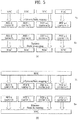
- FIG. 5 is a diagram illustrating configurations of a physical (PHY) layer (a first layer, L1) and a MAC layer (a second layer, L2) in a multiple carrier support system.
- PHY physical
- a PHY object for supporting one carrier is present, and one medium access control (MAC) object for controlling one PHY object may be provided.
- a PHY layer for example, a baseband processing operation may be performed.
- a transmitter may generate a MAC protocol data unit (MAC PDU) and perform an L1/L2 scheduler operation over MAC/RLC sublayers.
- a MAC PDU packet of the MAC layer is converted into a transport block through a logical transfer layer and is then mapped to a PHY layer input information block.
- the MAC layer illustrated in FIG. 5 may be represented by all the layers L2 and may be interpreted as including MAC/RLC/PDCP sublayers. This application may be applied in the same way in the detailed description of the MAC layer throughout this specification.
- a plurality of MAC-PHY objects may be provided. That is, as illustrated in FIG. 5(A) , a transmitter and a receiver of the multiple carrier support system may be configured such that one MAC-PHY object corresponds to each of n configured carriers. An independent PHY layer and MAC layer are configured for each of the configured carriers, and thus, a PDSCH is generated for each of the configured carriers in a PHY layer from the MAC PDU.
- one common MAC object and a plurality of PHY objects may be configured. That is, as illustrated in FIG. 5(B) , a transmitter and a receiver of the multiple carrier support system may be configured such that n PHY objects respectively corresponding to the n configured carriers are provided and one common MAC object for controlling the n PHY objects is present.
- the MAC PDU from one MAC layer may be divided into a plurality of transmission blocks respectively corresponding to the plural configured carriers on a transmission layer.
- the MAC PDU may be divided for the respective configured carriers.
- a PDSCH is generated per configured carrier on a PHY layer.
- FIG. 6 is a diagram illustrating a general structure for E-UTRAN MBMS.
- an E-UTRAN includes a multi-cell/multicast coordination entity (MCE) and an eNode.
- the MCE and the eNode are connected via an M2 interface.
- the M2 interface is a control plane interface in the E-UTRAN.
- An evolved packet core (EPC) includes an MME and an MBMS gateway (MBMS GW).
- the MME and the MBMS GW are connected via an Sm interface.
- the MCE of the E-UTRAN and the MME of the EPC are connected via an M3 interface.
- the eNode of the E-UTRAN is connected to the MBMS GW of the EPC via an M1 interface.
- the M3 interface is a control plane interface between the E-UTRAN and the EPC and the M1 interface is a user plane interface.
- the MBMS GW may be connected to a plurality of BSs via the M1 interface for data distribution.
- the MCE may be connected to one or more BSs in the same MBSFN via the M2 interface for MBMS session management signaling and wireless configuration signaling.
- DL/UL ratios various ratios between numbers of downlink subframes and uplink subframes are defined, but one DL/UL ratio is used per multi-cell in principle.
- traffic volumes between cells are different, and thus, a dynamic-TDD (D-TDD) system for adjusting and using a DL/UL ratio based on traffic volume between cells is required.
- D-TDD dynamic-TDD
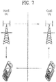
- FIG. 7 is a diagram for conceptually explaining interference modeling in a D-TDD system.
- interference may occur. Interference may occur due to un-aligned downlink/uplink (DL/UL) (e.g., downlink subframe/uplink subframe) allocation between BSs.
- DL/UL un-aligned downlink/uplink
- the Hcell and the Ocell may have different DL/UL ratios in the same carrier. An uplink section and a downlink section between the Hcell and the Ocell are changed, and thus, interference may occur.
- the Hcell when a specific time duration configured in the Hcell is allocated to a downlink section, the Hcell transmits a downlink signal to a UE 1 in the downlink section.
- a UE 2 when the specific time duration is allocated to an uplink section, a UE 2 transmits an uplink signal to the Ocell in the specific time duration.
- downlink transmission in the specific time duration of the Hcell interferes in the Ocell, and uplink transmission in the specific time duration of the UE 2 interferes in the UE 1.
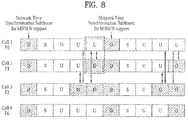
- FIG. 8 is a diagram illustrating of a collision (or interference) model of a subframe level based on DL/UL configuration in the 3GPP LTE TDD shown in Table 2 above in a D-TDD system.
- FIG. 8 illustrates an example in which a BS 1 has DL/UL configuration 0 of Table 2, a BS 2 has DL/UL configuration 1, a BS 3 has DL/UL configuration 2, and a BS 4 has DL/UL configuration 6.
- a model of highest interference receiving performance of a UE of a cell in a downlink transmission section is reduced by uplink transmission power of the UE of the cell in an uplink transmission section.
- higher interference may occur.
- the number of cells having the uplink transmission section among cells adjacent to a cell corresponding to the downlink transmission section may significantly affect the receiving performance.
- problems may arise in terms of coexistence with a heterogeneous TDD system may arise.
- problems may arise in terms of coexistence with a heterogeneous TDD system may arise.
- additional interference may occur due to DL/UL timing mismatch.
- MCSFN multicast channel subframe allocation pattern
- a method for a neighbor cell as a downlink section in a cell as an uplink section is considered.
- a method of removing interference for the neighbor cell as the downlink section in the cell as the uplink section a method of reducing uplink transmission power for power control may be considered.
- symbol level power control is applied during uplink transmission, and originally calculated total power is maintained.
- Transmission power [dBm/mW] power calculated using power control [dBm/mW] - Offset[dB/mW], and an offset value may be signaled (for example, in a unicast message type) by a BS or may be applied to a preset level by a UE.
- scheduling may be configured in such a way that uplink transmission in a cell 2 is not performed in the downlink section of a cell 1.
- User (users in a cell) selection may be performed based on SINR, geographic distribution from a BS in a cell, etc.
- network statistics may be used.
- D-TDD dynamic-TDD
- a BS-specific component carrier (CC) between BSs may be configured.
- a method in which neighbor BSs use CC for D-TDD while avoiding each other based on a BS-specific CC index (or a UE-specific CC index) may be considered. That is, the D-TDD may be used in different BS-specific CC indexes or UE-specific CC indexes.
- a BS using two or more CCs may use some of CCs for D-TDD and may not use other CCs for D-TDD in consideration of a relationship with neighbor BSs.
- the BS may use a CC configured not to use D-TDD and use a TDD configuration set that exerts minimum interference on TDD configuration of neighbor BSs. As the number of available CCs is increased, interference due to use of D-TDD may be reduced.
- a deactivated CC among configured CCs may be applied in consideration of the above features.
- the collision cell coordination method limits the number of cells as an uplink section adjacent to cells as a downlink section or limits the number of cells as a downlink transmission section adjacent to cells as an uplink section.
- whether D-TDD support of a neighbor BS is activated may be shared to be pre-recognized and whether the collision cell coordination method is used may be determined.
- a BS may simultaneously transmit time delay information to a neighbor BS.
- the neighbor BS receiving the time delay information may perform D-TDD in a corresponding cell after the requested time delay duration.
- DL/UL configuration sets For configuration of a DL/UL configuration set that exerts low interference influence, DL/UL configuration sets, the number of which corresponds to collision subframes, may be configured as shown in Table 7 below.
- Table 7 The number of collision subframe Rel.8/9/10 : TDD DL/UL configurations 1 (0,6) (1,6), (3,4), (4,5) 1.5 (2,5) 2 (0,1), (1,2), (3,5) 2.5 (1,4), (2,4), (3,6) 3.5 (0,3), (1,3), (1,5), (2,3), (2,6), (4,6) 4 (0,2) 4.5 (0,4), (5,6) 5.5 (0,5)
- collision subframes refer to subframes that exert interference influence by allocating different subframes (e.g., an uplink subframe, a downlink subframe, and a special subframe) to respective subframe indexes in a plurality of TDD DL/UL configurations.
- the number of collision subframes between cells may be from 1 to 5.5.
- the number of collision subframes may be minimized.
- the number of collision subframes may be increased.
- a case in which a special subframe S of a specific cell collides with an uplink subframe U or a downlink subframe D of another cell is denoted by 0.5.
- a DL/UL configuration set that exerts low interference may be configured, and a method of adjusting the number of neighbor cells in order to reduce interference while using the DL/UL configuration set may be used.
- Combination configuration of DL/UL configurations of Table 7 may be set by a network node (for example, a BS). Then, the set DL/UL configuration information may be shared between a BS and neighbor BSs and may be signaled to a UE.
- a method using RA only in UpPTS of a first half-frame in a subframe set may reduce RA performance attenuation.
- PRACH physical random access channel
- a special subframe exists only in a second subframe in a first radio frame (10 ms), and thus, interference between BSs may be exerted from a downlink transmission section of configurations 3, 4, and 5 on UpPTS of a second special subframe that exists at a period of 5 ms, like DL/UL configurations 0, 1, 2, and 6.
- a UE may further compensate an initial setting power level compared with a conventional power level and may perform transmission during RA transmission, thereby increasing probability of success of initial RA.
- a PRACH transmission section may be indicated to a UE such that a BS may not collide with a subframe of a cell as a downlink transmission section.
- the BS may inform the UE of the PRACH transmission section that does not collide with a downlink transmission section subframe of the BS in the index form as a downlink broadcast message type. Then, the UE may perform RA in the PRACH transmission section corresponding to a subframe index received from the BS.
- FIG. 9 is a diagram illustrating an example of a network structure for support of MBMS in a 3GPP LTE.
- the network may include a multi-cell/multicast coordination entity (MCE), an eNode, and a MBMS gateway (MBMS GW).
- MCE multi-cell/multicast coordination entity
- eNode eNode
- MBMS gateway MBMS gateway
- the MCE and the eNode may be connected via an M2 interface as a control plane interface in E-UTRAN.
- the eNode and the MBMS GW are connected via an M1 interface.
- the MCE and the MBMS GW are connected via an M3 interface.
- a MBSFN subframe corresponds to a subframe corresponding to subframe indexes 0, 1, 5, and 6 and a downlink subframe except for an uplink transmission subframe section.
- the eNode may transmit MBSFN data in the MBSFN subframe.
- Table 2 seven DL/UL configurations shown in Table 2 above defined in a current LTE/LTE-A system, when a DL/UL configuration 0 and a different DL/UL configuration are simultaneously used, MBSFN support is not possible.
- corresponding eNodes supporting MBSFN are required to include DL/UL configurations except for at least the configuration 0.
- a subframe 9 corresponding to a subframe index 9 is always a common section in the remaining DL/UL configurations except for the configuration 0. Based on this, the number of (common) SFN subframes may be combined using a conventional DL/UL configuration.
- predetermined DL/UL configurations need to be limited in order to have at least one SFN subframes in TDD, as shown in Table 8 below.
- Table 8 Number SFN support subframe index DL/UL configurations set 1 #9 (1,6), (1,3), (3,6) 2 #4, #9 (1, 2), (1, 4), (1, 5), #8, #9 (2,3) 4 #3, #4, #8, #9 (2,5)
- the "number" of Table 8 refers to the number of subframes as all downlink sections in a subframe except for a MBSFN subframe in two arbitrary DL/UL configurations shown in Table 2 above.
- a DL/UL configuration set may include (configuration 1, configuration 6), (configuration 1, configuration 3), and (configuration 6, configuration 6).
- a DL/UL configuration set may include (configuration 1, configuration 2), (configuration 1, configuration 4), and (configuration 1, configuration 5).
- a DL/UL configuration set may include (configuration 2, configuration 3).
- a DL/UL configurations set may include (configuration 2, configuration 5).
- Information shown in Table 8 above may be configured by the MCE, may be transmitted to BSs, and may be shared by the BSs.
- BSs need to previously share the information and to have the same configuration with regard to RLC/MAC/PHY layers.
- the information is required for configuration of MBMS subframe allocation pattern (MSAP).
- a MBMS coordination entity MCE
- MCE MBMS coordination entity
- embodiments of the present invention preclude signaling via M1 and M3 interfaces.
- configuration information shown in Table 8 above may be shared between BSs via an X2 interface.
- An X2 interface message may contain subframe index information corresponding to a common downlink transmission section.
- the MCE may configure a DL/UL configuration in consideration of the number of (common) SFN subframes and the number of subframes that simultaneously collide in downlink and uplink. This is shown in Table 9 below. [Table 9] Number of collision subframes Number of SFN subframes DL/UL Configuration Set 1 1 (1,6) 1.5 4 (2,5) 2 2 (1,2) 2.5 1 (3,6) 2.5 2 (1,4) 3.5 1 (1,3) 3.5 2 (1,5) 3.5 2 (2,3)
- collision subframes refer to subframes that exert interference influence by allocating different subframes (e.g., an uplink subframe, a downlink subframe, and a special subframe) to respective subframe indexes in a plurality of TDD DL/UL configurations.
- a DL/UL configuration set may include (1,6).
- (1, 6) refers to (DL/UL Configuration 1, DL/UL Configuration 6).
- a DL/UL configuration set may include (2,5).
- a DL/UL configuration set may include (1, 2).
- a DL/UL configuration set may include (3, 6).
- a DL/UL configuration set may include (1, 4).
- a DL/UL configuration set may include (1, 3).
- a DL/UL configuration set may include (1, 5).
- a DL/UL configuration set may include (2, 3).
- the MCE may share information of the DL/UL configuration sets configured like in Table 9 above with BSs, and the BSs may exchange the information via an X2 interface.
- a method and apparatus for supporting dynamic-time division duplex (D-TDD) downlink-uplink configuration in a wireless communication system is industrially applicable to various communication systems such as systems of 3GPP LTE, LTE-A, IEEE 802, etc.
Claims (5)
- Verfahren zum Unterstützen einer Zeitteilungsduplex-, TDD, -Downlink-Uplink-Konfiguration durch eine Basisstation (105) in einem drahtlosen Kommunikationssystem (100), wobei das Verfahren umfasst:Empfangen eines TDD-Downlink-Uplink-Konfigurationssatzes von einer Nachbarbasisstation, wobei der TDD-Downlink-Uplink-Konfigurationssatz als eine aus ausgewählten Kombinationen von TDD-Downlink-Uplink-Konfigurationen gemäß einer vorbestimmten Regel unter einer Vielzahl vordefinierter TDD-Downlink-Uplink-Konfigurationen konfiguriert ist, wobei eine Gesamtanzahl von Unterrahmen unterschiedlicher Unterrahmenart in jedem Unterrahmenindex zwischen den ausgewählten Kombinationen von TDD-Downlink-Uplink-Konfigurationen gemäß der vorbestimmten Regel dieselbe ist, wobei die Unterrahmenarten der TDD-Downlink-Uplink-Konfiguration eine Downlink-Unterrahmenart, eine Uplink-Unterrahmenart und eine Sonderunterrahmenart umfassen; undDurchführen einer Kommunikation mit einer Benutzereinrichtung (110) unter Verwendung des TDD-Downlink-Uplink-Konfigurationssatzes der Vielzahl vordefinierter TDD-Downlink-Uplink-Konfigurationen.
- Verfahren gemäß Anspruch 1, wobei der TDD-Downlink-Uplink-Konfigurationssatz weiterhin auf der Grundlage einer Zahl eines Einzelfrequenznetzwerk-, SFN, -Unterstützungsunterrahmens in einer TDD-Downlink-Uplink-Konfiguration konfiguriert ist.
- Verfahren gemäß Anspruch 2, wobei die Zahl des SFN-Unterstützungsunterrahmens 1, 2 oder 4 umfasst.
- Basisstation (105) zum Unterstützen einer Zeitteilungsduplex-, TDD, - Downlink-Uplink-Konfiguration in einem drahtlosen Kommunikationssystem, wobei die Basisstation umfasst:einen Empfänger (190), der konfiguriert ist, um einen TDD-Downlink-Uplink-Konfigurationssatz von einer Nachbarbasisstation zu empfangen, wobei der TDD-Downlink-Uplink-Konfigurationssatz als eine aus ausgewählten Kombinationen von TDD-Downlink-Uplink-Konfigurationen gemäß einer vorbestimmten Regel unter einer Vielzahl vordefinierter TDD-Downlink-Uplinks konfiguriert ist, wobei eine Gesamtanzahl von Unterrahmen unterschiedlicher Unterrahmenart in jedem Unterrahmenindex zwischen den ausgewählten Kombinationen von TDD-Downlink-Uplink-Konfigurationen gemäß der vorbestimmten Regel dieselbe ist, und wobei Unterrahmenarten der TDD-Downlink-Uplink-Konfiguration eine Downlink-Unterrahmenart, eine Uplink-Unterrahmenart und eine Sonderunterrahmenart umfassen; undeinen Prozessor (180), der konfiguriert ist, um eine Kommunikation mit einer Benutzereinrichtung (110) unter Verwendung des TDD-Downlink-Uplink-Konfigurationssatzes der Vielzahl vordefinierter TDD-Downlink-Uplink-Konfigurationen durchzuführen.
- Basisstation (105) gemäß Anspruch 4, wobei der TDD-Downlink-Uplink-Konfigurationssatz weiterhin auf der Grundlage einer Zahl eines Einzelfrequenznetzwerk-, SFN, -Unterstützungsunterrahmens in einer TDD-Downlink-Uplink-Konfiguration konfiguriert wird.
Applications Claiming Priority (2)
| Application Number | Priority Date | Filing Date | Title |
|---|---|---|---|
| US201161448144P | 2011-03-01 | 2011-03-01 | |
| PCT/KR2012/001577 WO2012118345A2 (ko) | 2011-03-01 | 2012-03-02 | 무선통신 시스템에서 d-tdd(dynamic-time division duplex) 하향링크-상향링크 구성을 지원하는 방법 및 이를 위한 장치 |
Publications (3)
| Publication Number | Publication Date |
|---|---|
| EP2685646A2 EP2685646A2 (de) | 2014-01-15 |
| EP2685646A4 EP2685646A4 (de) | 2015-10-21 |
| EP2685646B1 true EP2685646B1 (de) | 2017-08-23 |
Family
ID=46758390
Family Applications (1)
| Application Number | Title | Priority Date | Filing Date |
|---|---|---|---|
| EP12752258.9A Not-in-force EP2685646B1 (de) | 2011-03-01 | 2012-03-02 | Verfahren zur unterstützung einer dynamic-time-division-duplex (d-tdd)-downlink-uplink-konfiguration in einem drahtlosen kommunikationssystem und vorrichtung dafür |
Country Status (3)
| Country | Link |
|---|---|
| US (1) | US9432136B2 (de) |
| EP (1) | EP2685646B1 (de) |
| WO (1) | WO2012118345A2 (de) |
Families Citing this family (17)
| Publication number | Priority date | Publication date | Assignee | Title |
|---|---|---|---|---|
| CN102685872B (zh) * | 2011-03-11 | 2015-01-21 | 华为技术有限公司 | 用于时分双工系统的通信方法和装置 |
| US9363847B2 (en) * | 2011-04-11 | 2016-06-07 | Broadcom Corporation | Method and apparatus for providing for discontinuous reception via cells having different time division duplex subframe configurations |
| JP2012249119A (ja) * | 2011-05-30 | 2012-12-13 | Sony Corp | 無線リソース割当方法及び無線リソース割当装置、並びに通信システム |
| CN102291227B (zh) * | 2011-06-30 | 2013-07-10 | 电信科学技术研究院 | 一种发送和接收反馈信息的方法、系统及装置 |
| EP2847895B1 (de) * | 2012-05-10 | 2017-12-06 | Samsung Electronics Co., Ltd. | Verfahren und vorrichtung zum senden und empfangen von rahmenkonfigurationsinformationen in einem drahtlosen zeitteilungsduplex-kommunikationssystem |
| JP2013251860A (ja) | 2012-06-04 | 2013-12-12 | Ntt Docomo Inc | 通信制御方法、無線通信システム、無線基地局及びユーザ端末 |
| CN103582000A (zh) * | 2012-08-10 | 2014-02-12 | 北京三星通信技术研究有限公司 | 一种干扰协调方法 |
| WO2014049169A1 (en) * | 2012-09-28 | 2014-04-03 | Nokia Siemens Networks Oy | Timing indication for dynamic time division duplex (tdd) uplink/downlink (ul/dl) reconfiguration |
| US9628251B2 (en) * | 2012-11-29 | 2017-04-18 | Mediatek, Inc. | UE measurement enhancement in adaptive TDD configuration networks |
| US9681482B2 (en) | 2013-01-07 | 2017-06-13 | Lg Electronics Inc. | Method and apparatus for transmitting/receiving signals with a value indicated by a TPC command being accumulated for all parameter sets |
| WO2014129849A1 (ko) | 2013-02-21 | 2014-08-28 | 엘지전자 주식회사 | 무선 통신 시스템에서 공통 설정 기반 운영 방법 및 이를 지원하는 장치 |
| US10390280B2 (en) | 2013-03-25 | 2019-08-20 | Telefonaktiebolaget Lm Ericsson (Publ) | Method for initiating handover, wireless device and base station |
| CN104780608B (zh) * | 2014-01-13 | 2019-10-18 | 中兴通讯股份有限公司 | 配置信息的下发、处理方法及装置 |
| US10122488B2 (en) | 2014-02-18 | 2018-11-06 | Lg Electronics Inc. | Method for transreceiving signals using user-specific flexible TDD technology in wireless communication system and device for same |
| US9775151B2 (en) * | 2014-07-21 | 2017-09-26 | Intel IP Corporation | System and method for TDD communications |
| US9980279B2 (en) | 2015-07-24 | 2018-05-22 | Taiwan Semiconductor Manufacturing Company, Ltd. | Dynamic time division duplex mechanism for small cell network |
| US10951386B2 (en) | 2018-09-20 | 2021-03-16 | At&T Intellectual Property I, L.P. | Indication of interoperability and deployment tested time-division duplex slot formats |
Family Cites Families (6)
| Publication number | Priority date | Publication date | Assignee | Title |
|---|---|---|---|---|
| US20060099987A1 (en) * | 2004-11-05 | 2006-05-11 | Nextel Communications, Inc. | System and method of providing data fill application to support large-scale configuration changes |
| KR101243864B1 (ko) | 2006-11-20 | 2013-03-25 | 한국과학기술원 | 이동통신 시스템에서 트래픽 비대칭성을 지원하기 위한하이브리드 시간 분할 듀플렉스 장치 및 방법 |
| KR100866568B1 (ko) | 2007-01-26 | 2008-11-03 | 삼성탈레스 주식회사 | 다중 홉 무선 네트워크에서 자원을 배분하는 방법 |
| EP2266362A4 (de) | 2008-03-24 | 2012-06-20 | Zte Usa Inc | Dynamische einstellung und signalisierung des downlink/uplink-zuteilungsverhältnisses in lte/tdd-systemen |
| WO2010061053A1 (en) | 2008-11-25 | 2010-06-03 | Nokia Corporation | Relay node backhauling |
| US9100980B2 (en) * | 2010-03-08 | 2015-08-04 | Nokia Solutions And Networks Oy | Method, network element and system for scheduling communication link |
-
2012
- 2012-03-02 EP EP12752258.9A patent/EP2685646B1/de not_active Not-in-force
- 2012-03-02 US US14/002,512 patent/US9432136B2/en active Active
- 2012-03-02 WO PCT/KR2012/001577 patent/WO2012118345A2/ko active Application Filing
Non-Patent Citations (1)
| Title |
|---|
| None * |
Also Published As
| Publication number | Publication date |
|---|---|
| EP2685646A2 (de) | 2014-01-15 |
| WO2012118345A3 (ko) | 2012-11-15 |
| EP2685646A4 (de) | 2015-10-21 |
| US9432136B2 (en) | 2016-08-30 |
| US20140036738A1 (en) | 2014-02-06 |
| WO2012118345A2 (ko) | 2012-09-07 |
Similar Documents
| Publication | Publication Date | Title |
|---|---|---|
| EP2685646B1 (de) | Verfahren zur unterstützung einer dynamic-time-division-duplex (d-tdd)-downlink-uplink-konfiguration in einem drahtlosen kommunikationssystem und vorrichtung dafür | |
| KR102544449B1 (ko) | 무선 통신 시스템에서 무선 신호 송수신 방법 및 장치 | |
| EP2775639B1 (de) | Verfahren zur bestimmung der übertragungsleistung eines srs-referenzsignals in einem drahtlosen kommunikationssystem und endgerät dafür | |
| EP2728774B1 (de) | Verfahren und vorrichtung zur steuerung der zwischenzellinterferenz in einem drahtlosen kommunikationssystem | |
| US9226247B2 (en) | Method for terminal deciding uplink transmission power in macro cell environment comprising remote radio head (RRH), and terminal apparatus for same | |
| EP2723009B1 (de) | Verfahren zum abrufen von downlink-steuerinformationen in einem drahtlosen zugangssystem und endgerät dafür | |
| US9225503B2 (en) | Method for transmitting/receiving data in wireless communication system and base station for same | |
| EP3518444B1 (de) | Verfahren zum empfangen von downlink-steuerinformationen durch eine benutzervorrichtung in einem drahtloskommunikationssystem und vorrichtung dafür | |
| EP2509366B1 (de) | Endgerät zum empfangen von signalen in einem drahtlosen kommunikationssystem zur unterstützung mehrerer komponententräger sowie verfahren dafür | |
| US9549395B2 (en) | Method for dynamic allocation of radio resources in wireless communication system and device therefor | |
| EP2763338A1 (de) | Verfahren und vorrichtung zur übertragung von kanalstatusinformationen in einem drahtlosen kommunikationssystem | |
| US10117239B2 (en) | Method for transmitting signal using plurality of antenna ports and transmission end apparatus for same | |
| KR20140097321A (ko) | 무선통신 시스템에서 상향링크 전송 전력을 설정하는 방법 및 이를 위한 장치 | |
| US20170187416A1 (en) | Method for allowing user equipment (ue) to perform ue-flexible time division duplex (tdd) mode communication in network configured to support ue-flexible tdd mode in which base station (bs) operates in full duplex mode and ue operates in half duplex mode, and the user equipment (ue) for the same | |
| KR102201754B1 (ko) | 반송파 집성(carrier aggregation)을 이용한 통신 방법 및 이를 위한 장치 | |
| WO2013066100A1 (ko) | 무선 접속 시스템에서 하향링크 제어 정보 송수신 방법 및 이를 위한 장치 | |
| WO2012150775A9 (ko) | 무선 통신 시스템에서 단말이 기지국과 신호를 송수신하는 방법 및 이를 위한 장치 | |
| US20150124729A1 (en) | Method for receiving downlink control channel by means of terminal in wireless communication system and apparatus for same | |
| EP3190738A1 (de) | Signalübertragungs- und -empfangsverfahren in einem drahtloskommunikationssystem mit trägeraggregationsunterstützung und vorrichtung dafür | |
| US20150003346A1 (en) | Method for transmitting and receiving ue-specific reference signal and apparatus for same | |
| KR20140050666A (ko) | 무선통신 시스템에서 상향링크 제어 정보를 전송하는 방법 및 장치 | |
| EP2690808B1 (de) | Verfahren zum über eine basisstation erfolgenden senden und empfangen von tdd-konfigurationsinformationen über mehrere ccs in einem drahtlosen kommunikationssystem zur unterstützung mehrerer ccs und vorrichtung dafür | |
| EP2863571B1 (de) | Verfahren und vorrichtung zur harq-durchführung auf basis einer dynamischer änderung drahtloser ressourcen in einem drahtlosen kommunikationssystem |
Legal Events
| Date | Code | Title | Description |
|---|---|---|---|
| PUAI | Public reference made under article 153(3) epc to a published international application that has entered the european phase |
Free format text: ORIGINAL CODE: 0009012 |
|
| 17P | Request for examination filed |
Effective date: 20130912 |
|
| AK | Designated contracting states |
Kind code of ref document: A2 Designated state(s): AL AT BE BG CH CY CZ DE DK EE ES FI FR GB GR HR HU IE IS IT LI LT LU LV MC MK MT NL NO PL PT RO RS SE SI SK SM TR |
|
| DAX | Request for extension of the european patent (deleted) | ||
| A4 | Supplementary search report drawn up and despatched |
Effective date: 20150918 |
|
| RIC1 | Information provided on ipc code assigned before grant |
Ipc: H04J 11/00 20060101AFI20150914BHEP Ipc: H04L 5/22 20060101ALI20150914BHEP |
|
| 17Q | First examination report despatched |
Effective date: 20160711 |
|
| REG | Reference to a national code |
Ref country code: DE Ref legal event code: R079 Ref document number: 602012036328 Country of ref document: DE Free format text: PREVIOUS MAIN CLASS: H04J0011000000 Ipc: H04B0007260000 |
|
| GRAP | Despatch of communication of intention to grant a patent |
Free format text: ORIGINAL CODE: EPIDOSNIGR1 |
|
| INTG | Intention to grant announced |
Effective date: 20170310 |
|
| RIC1 | Information provided on ipc code assigned before grant |
Ipc: H04B 7/26 20060101AFI20170301BHEP Ipc: H04L 5/14 20060101ALI20170301BHEP Ipc: H04W 72/12 20090101ALN20170301BHEP Ipc: H04J 3/16 20060101ALI20170301BHEP |
|
| GRAS | Grant fee paid |
Free format text: ORIGINAL CODE: EPIDOSNIGR3 |
|
| GRAA | (expected) grant |
Free format text: ORIGINAL CODE: 0009210 |
|
| AK | Designated contracting states |
Kind code of ref document: B1 Designated state(s): AL AT BE BG CH CY CZ DE DK EE ES FI FR GB GR HR HU IE IS IT LI LT LU LV MC MK MT NL NO PL PT RO RS SE SI SK SM TR |
|
| REG | Reference to a national code |
Ref country code: GB Ref legal event code: FG4D |
|
| REG | Reference to a national code |
Ref country code: CH Ref legal event code: EP |
|
| REG | Reference to a national code |
Ref country code: AT Ref legal event code: REF Ref document number: 922355 Country of ref document: AT Kind code of ref document: T Effective date: 20170915 |
|
| REG | Reference to a national code |
Ref country code: IE Ref legal event code: FG4D |
|
| REG | Reference to a national code |
Ref country code: DE Ref legal event code: R096 Ref document number: 602012036328 Country of ref document: DE |
|
| REG | Reference to a national code |
Ref country code: NL Ref legal event code: MP Effective date: 20170823 |
|
| REG | Reference to a national code |
Ref country code: LT Ref legal event code: MG4D |
|
| REG | Reference to a national code |
Ref country code: AT Ref legal event code: MK05 Ref document number: 922355 Country of ref document: AT Kind code of ref document: T Effective date: 20170823 |
|
| PG25 | Lapsed in a contracting state [announced via postgrant information from national office to epo] |
Ref country code: NL Free format text: LAPSE BECAUSE OF FAILURE TO SUBMIT A TRANSLATION OF THE DESCRIPTION OR TO PAY THE FEE WITHIN THE PRESCRIBED TIME-LIMIT Effective date: 20170823 Ref country code: NO Free format text: LAPSE BECAUSE OF FAILURE TO SUBMIT A TRANSLATION OF THE DESCRIPTION OR TO PAY THE FEE WITHIN THE PRESCRIBED TIME-LIMIT Effective date: 20171123 Ref country code: AT Free format text: LAPSE BECAUSE OF FAILURE TO SUBMIT A TRANSLATION OF THE DESCRIPTION OR TO PAY THE FEE WITHIN THE PRESCRIBED TIME-LIMIT Effective date: 20170823 Ref country code: HR Free format text: LAPSE BECAUSE OF FAILURE TO SUBMIT A TRANSLATION OF THE DESCRIPTION OR TO PAY THE FEE WITHIN THE PRESCRIBED TIME-LIMIT Effective date: 20170823 Ref country code: LT Free format text: LAPSE BECAUSE OF FAILURE TO SUBMIT A TRANSLATION OF THE DESCRIPTION OR TO PAY THE FEE WITHIN THE PRESCRIBED TIME-LIMIT Effective date: 20170823 Ref country code: SE Free format text: LAPSE BECAUSE OF FAILURE TO SUBMIT A TRANSLATION OF THE DESCRIPTION OR TO PAY THE FEE WITHIN THE PRESCRIBED TIME-LIMIT Effective date: 20170823 Ref country code: FI Free format text: LAPSE BECAUSE OF FAILURE TO SUBMIT A TRANSLATION OF THE DESCRIPTION OR TO PAY THE FEE WITHIN THE PRESCRIBED TIME-LIMIT Effective date: 20170823 |
|
| PG25 | Lapsed in a contracting state [announced via postgrant information from national office to epo] |
Ref country code: IS Free format text: LAPSE BECAUSE OF FAILURE TO SUBMIT A TRANSLATION OF THE DESCRIPTION OR TO PAY THE FEE WITHIN THE PRESCRIBED TIME-LIMIT Effective date: 20171223 Ref country code: PL Free format text: LAPSE BECAUSE OF FAILURE TO SUBMIT A TRANSLATION OF THE DESCRIPTION OR TO PAY THE FEE WITHIN THE PRESCRIBED TIME-LIMIT Effective date: 20170823 Ref country code: ES Free format text: LAPSE BECAUSE OF FAILURE TO SUBMIT A TRANSLATION OF THE DESCRIPTION OR TO PAY THE FEE WITHIN THE PRESCRIBED TIME-LIMIT Effective date: 20170823 Ref country code: BG Free format text: LAPSE BECAUSE OF FAILURE TO SUBMIT A TRANSLATION OF THE DESCRIPTION OR TO PAY THE FEE WITHIN THE PRESCRIBED TIME-LIMIT Effective date: 20171123 Ref country code: RS Free format text: LAPSE BECAUSE OF FAILURE TO SUBMIT A TRANSLATION OF THE DESCRIPTION OR TO PAY THE FEE WITHIN THE PRESCRIBED TIME-LIMIT Effective date: 20170823 Ref country code: GR Free format text: LAPSE BECAUSE OF FAILURE TO SUBMIT A TRANSLATION OF THE DESCRIPTION OR TO PAY THE FEE WITHIN THE PRESCRIBED TIME-LIMIT Effective date: 20171124 Ref country code: LV Free format text: LAPSE BECAUSE OF FAILURE TO SUBMIT A TRANSLATION OF THE DESCRIPTION OR TO PAY THE FEE WITHIN THE PRESCRIBED TIME-LIMIT Effective date: 20170823 |
|
| PG25 | Lapsed in a contracting state [announced via postgrant information from national office to epo] |
Ref country code: CZ Free format text: LAPSE BECAUSE OF FAILURE TO SUBMIT A TRANSLATION OF THE DESCRIPTION OR TO PAY THE FEE WITHIN THE PRESCRIBED TIME-LIMIT Effective date: 20170823 Ref country code: RO Free format text: LAPSE BECAUSE OF FAILURE TO SUBMIT A TRANSLATION OF THE DESCRIPTION OR TO PAY THE FEE WITHIN THE PRESCRIBED TIME-LIMIT Effective date: 20170823 Ref country code: DK Free format text: LAPSE BECAUSE OF FAILURE TO SUBMIT A TRANSLATION OF THE DESCRIPTION OR TO PAY THE FEE WITHIN THE PRESCRIBED TIME-LIMIT Effective date: 20170823 |
|
| REG | Reference to a national code |
Ref country code: DE Ref legal event code: R097 Ref document number: 602012036328 Country of ref document: DE |
|
| PG25 | Lapsed in a contracting state [announced via postgrant information from national office to epo] |
Ref country code: SK Free format text: LAPSE BECAUSE OF FAILURE TO SUBMIT A TRANSLATION OF THE DESCRIPTION OR TO PAY THE FEE WITHIN THE PRESCRIBED TIME-LIMIT Effective date: 20170823 Ref country code: SM Free format text: LAPSE BECAUSE OF FAILURE TO SUBMIT A TRANSLATION OF THE DESCRIPTION OR TO PAY THE FEE WITHIN THE PRESCRIBED TIME-LIMIT Effective date: 20170823 Ref country code: IT Free format text: LAPSE BECAUSE OF FAILURE TO SUBMIT A TRANSLATION OF THE DESCRIPTION OR TO PAY THE FEE WITHIN THE PRESCRIBED TIME-LIMIT Effective date: 20170823 Ref country code: EE Free format text: LAPSE BECAUSE OF FAILURE TO SUBMIT A TRANSLATION OF THE DESCRIPTION OR TO PAY THE FEE WITHIN THE PRESCRIBED TIME-LIMIT Effective date: 20170823 |
|
| PLBE | No opposition filed within time limit |
Free format text: ORIGINAL CODE: 0009261 |
|
| STAA | Information on the status of an ep patent application or granted ep patent |
Free format text: STATUS: NO OPPOSITION FILED WITHIN TIME LIMIT |
|
| 26N | No opposition filed |
Effective date: 20180524 |
|
| PG25 | Lapsed in a contracting state [announced via postgrant information from national office to epo] |
Ref country code: SI Free format text: LAPSE BECAUSE OF FAILURE TO SUBMIT A TRANSLATION OF THE DESCRIPTION OR TO PAY THE FEE WITHIN THE PRESCRIBED TIME-LIMIT Effective date: 20170823 |
|
| REG | Reference to a national code |
Ref country code: CH Ref legal event code: PL |
|
| PG25 | Lapsed in a contracting state [announced via postgrant information from national office to epo] |
Ref country code: MC Free format text: LAPSE BECAUSE OF FAILURE TO SUBMIT A TRANSLATION OF THE DESCRIPTION OR TO PAY THE FEE WITHIN THE PRESCRIBED TIME-LIMIT Effective date: 20170823 |
|
| REG | Reference to a national code |
Ref country code: BE Ref legal event code: MM Effective date: 20180331 |
|
| REG | Reference to a national code |
Ref country code: IE Ref legal event code: MM4A |
|
| PG25 | Lapsed in a contracting state [announced via postgrant information from national office to epo] |
Ref country code: LU Free format text: LAPSE BECAUSE OF NON-PAYMENT OF DUE FEES Effective date: 20180302 |
|
| PG25 | Lapsed in a contracting state [announced via postgrant information from national office to epo] |
Ref country code: IE Free format text: LAPSE BECAUSE OF NON-PAYMENT OF DUE FEES Effective date: 20180302 |
|
| PG25 | Lapsed in a contracting state [announced via postgrant information from national office to epo] |
Ref country code: BE Free format text: LAPSE BECAUSE OF NON-PAYMENT OF DUE FEES Effective date: 20180331 Ref country code: LI Free format text: LAPSE BECAUSE OF NON-PAYMENT OF DUE FEES Effective date: 20180331 Ref country code: CH Free format text: LAPSE BECAUSE OF NON-PAYMENT OF DUE FEES Effective date: 20180331 |
|
| PG25 | Lapsed in a contracting state [announced via postgrant information from national office to epo] |
Ref country code: FR Free format text: LAPSE BECAUSE OF NON-PAYMENT OF DUE FEES Effective date: 20180331 |
|
| PG25 | Lapsed in a contracting state [announced via postgrant information from national office to epo] |
Ref country code: MT Free format text: LAPSE BECAUSE OF NON-PAYMENT OF DUE FEES Effective date: 20180302 |
|
| PG25 | Lapsed in a contracting state [announced via postgrant information from national office to epo] |
Ref country code: TR Free format text: LAPSE BECAUSE OF FAILURE TO SUBMIT A TRANSLATION OF THE DESCRIPTION OR TO PAY THE FEE WITHIN THE PRESCRIBED TIME-LIMIT Effective date: 20170823 |
|
| PGFP | Annual fee paid to national office [announced via postgrant information from national office to epo] |
Ref country code: DE Payment date: 20200211 Year of fee payment: 9 Ref country code: GB Payment date: 20200213 Year of fee payment: 9 |
|
| PG25 | Lapsed in a contracting state [announced via postgrant information from national office to epo] |
Ref country code: HU Free format text: LAPSE BECAUSE OF FAILURE TO SUBMIT A TRANSLATION OF THE DESCRIPTION OR TO PAY THE FEE WITHIN THE PRESCRIBED TIME-LIMIT; INVALID AB INITIO Effective date: 20120302 Ref country code: PT Free format text: LAPSE BECAUSE OF FAILURE TO SUBMIT A TRANSLATION OF THE DESCRIPTION OR TO PAY THE FEE WITHIN THE PRESCRIBED TIME-LIMIT Effective date: 20170823 |
|
| PG25 | Lapsed in a contracting state [announced via postgrant information from national office to epo] |
Ref country code: MK Free format text: LAPSE BECAUSE OF NON-PAYMENT OF DUE FEES Effective date: 20170823 Ref country code: CY Free format text: LAPSE BECAUSE OF FAILURE TO SUBMIT A TRANSLATION OF THE DESCRIPTION OR TO PAY THE FEE WITHIN THE PRESCRIBED TIME-LIMIT Effective date: 20170823 |
|
| PG25 | Lapsed in a contracting state [announced via postgrant information from national office to epo] |
Ref country code: AL Free format text: LAPSE BECAUSE OF FAILURE TO SUBMIT A TRANSLATION OF THE DESCRIPTION OR TO PAY THE FEE WITHIN THE PRESCRIBED TIME-LIMIT Effective date: 20170823 |
|
| REG | Reference to a national code |
Ref country code: DE Ref legal event code: R119 Ref document number: 602012036328 Country of ref document: DE |
|
| GBPC | Gb: european patent ceased through non-payment of renewal fee |
Effective date: 20210302 |
|
| PG25 | Lapsed in a contracting state [announced via postgrant information from national office to epo] |
Ref country code: GB Free format text: LAPSE BECAUSE OF NON-PAYMENT OF DUE FEES Effective date: 20210302 Ref country code: DE Free format text: LAPSE BECAUSE OF NON-PAYMENT OF DUE FEES Effective date: 20211001 |