EP2685437B1 - Fire sensor - Google Patents
Fire sensor Download PDFInfo
- Publication number
- EP2685437B1 EP2685437B1 EP12758282.3A EP12758282A EP2685437B1 EP 2685437 B1 EP2685437 B1 EP 2685437B1 EP 12758282 A EP12758282 A EP 12758282A EP 2685437 B1 EP2685437 B1 EP 2685437B1
- Authority
- EP
- European Patent Office
- Prior art keywords
- light
- smoke sensing
- space
- smoke
- receiving unit
- Prior art date
- Legal status (The legal status is an assumption and is not a legal conclusion. Google has not performed a legal analysis and makes no representation as to the accuracy of the status listed.)
- Active
Links
Images

Classifications
-
- G—PHYSICS
- G08—SIGNALLING
- G08B—SIGNALLING SYSTEMS, e.g. PERSONAL CALLING SYSTEMS; ORDER TELEGRAPHS; ALARM SYSTEMS
- G08B17/00—Fire alarms; Alarms responsive to explosion
- G08B17/10—Actuation by presence of smoke or gases, e.g. automatic alarm devices for analysing flowing fluid materials by the use of optical means
- G08B17/103—Actuation by presence of smoke or gases, e.g. automatic alarm devices for analysing flowing fluid materials by the use of optical means using a light emitting and receiving device
- G08B17/107—Actuation by presence of smoke or gases, e.g. automatic alarm devices for analysing flowing fluid materials by the use of optical means using a light emitting and receiving device for detecting light-scattering due to smoke
-
- G—PHYSICS
- G01—MEASURING; TESTING
- G01N—INVESTIGATING OR ANALYSING MATERIALS BY DETERMINING THEIR CHEMICAL OR PHYSICAL PROPERTIES
- G01N21/00—Investigating or analysing materials by the use of optical means, i.e. using sub-millimetre waves, infrared, visible or ultraviolet light
- G01N21/17—Systems in which incident light is modified in accordance with the properties of the material investigated
- G01N21/47—Scattering, i.e. diffuse reflection
- G01N21/49—Scattering, i.e. diffuse reflection within a body or fluid
- G01N21/53—Scattering, i.e. diffuse reflection within a body or fluid within a flowing fluid, e.g. smoke
-
- G—PHYSICS
- G08—SIGNALLING
- G08B—SIGNALLING SYSTEMS, e.g. PERSONAL CALLING SYSTEMS; ORDER TELEGRAPHS; ALARM SYSTEMS
- G08B17/00—Fire alarms; Alarms responsive to explosion
- G08B17/06—Electric actuation of the alarm, e.g. using a thermally-operated switch
-
- G—PHYSICS
- G08—SIGNALLING
- G08B—SIGNALLING SYSTEMS, e.g. PERSONAL CALLING SYSTEMS; ORDER TELEGRAPHS; ALARM SYSTEMS
- G08B17/00—Fire alarms; Alarms responsive to explosion
- G08B17/10—Actuation by presence of smoke or gases, e.g. automatic alarm devices for analysing flowing fluid materials by the use of optical means
- G08B17/11—Actuation by presence of smoke or gases, e.g. automatic alarm devices for analysing flowing fluid materials by the use of optical means using an ionisation chamber for detecting smoke or gas
- G08B17/113—Constructional details
Definitions
- the present invention relates to a fire sensor for detecting a fire by sensing smoke and heat.
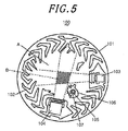
- a fire sensor 100 includes a smoke sensing chamber 101 around which a plurality of labyrinth walls 102 is installed, a light emitting unit 103 for irradiating light into a smoke sensing space A of the smoke sensing chamber 101, a light receiving unit 104 arranged in a position where the light receiving unit 104 does not directly receive the light irradiated from the light emitting unit 103, and a thermistor 105.
- a light shield wall 106 for shielding the light irradiated from the light emitting unit 103 to the light receiving unit 104 without being scattered by smoke is installed upright in the smoke sensing space A.
- the light scattered by smoke in the smoke sensing region B is detected by the light receiving unit 104, thereby sensing the smoke.
- a through-hole 107 is formed in the light shield wall 106.
- the thermistor 105 is inserted into the through-hole 107.
- the thermistor 105 is installed upright on a substrate lying below the smoke sensing chamber 101 and is configured to detect a temperature.
- Patent Document 1 Japanese Patent Application Publication No. 11-185179
- the support member of the thermistor directly passes through the substantially central region of the smoke sensing space. Therefore, it is sometimes the case that the flow of smoke toward the smoke sensing space is hindered or the light is scattered.
- the volume of the light shield wall 106 is increased and the flow of smoke from the gaps between the labyrinth walls 102 toward the smoke sensing space A is inhibited. For that reason, it is often the case that the sensitivity of smoke sensing in the smoke sensing region is reduced and the response is delayed.
- EP 2 109 085 A2 describes a combination smoke and heat detector, comprising a body base; a printed circuit board mounted to the body base; a thermosensitive element provided upright on the printed circuit board; a dark chamber mounted to the printed circuit board, for shielding external light so that smoke particles flow therein; an indication lamp mounted to the printed circuit board; a protective cover which is provided with respective opening holes through which the thermosensitive element and the dark chamber pass, and engaged with the body base; and a bar-like light guide for guiding light emitted from the indication lamp to outside of the protective cover.
- EP 1 253 566 A2 describes a fire detector unit comprising a base made of a molded plastic to have a labyrinth wall which projects on the circumference of said base to define therein a smoke chamber, said labyrinth wall permitting an entry of smoke particles but prohibiting the entry of an ambient light into said smoke chamber; a light projector carried on said base and directing an incident light from a light emitting element into said smoke chamber; a light collector carried on said base and collecting a light scattered by the smoke particles in said smoke chamber to a light receiving element, said light receiving element generating an electric signal indicative of the amount of the light received; a fire detecting circuit being connected to receive said electric signal so as to provide a fire warning signal based upon said electric signal; and a circuit board mounting said light emitting element, said light receiving element, and electronic components forming said fire detecting circuit.
- a fire sensor including a heat sensor extending through a smoke sensing space, which is capable of suppressing the reduction of the smoke sensing sensitivity and response delay otherwise caused by the arrangement of the heat sensor.
- a fire sensor inter alia including: a plurality of labyrinth walls installed along a circumferential direction so as to surround a smoke sensing space; a light emitting unit arranged to irradiate light toward the smoke sensing space; a light receiving unit arranged in a position where the light receiving unit does not directly receive the light emitted from the light emitting unit; and a heat sensor, wherein the smoke sensing space includes a smoke sensing region defined by a light emission zone extending from the light emitting unit and a light reception zone extending from the light receiving unit, the fire sensor configured to detect a fire when the light receiving unit receives the scattered light of the light emitting unit generated in the smoke sensing region by smokes introduced into the smoke sensing space through gaps between the labyrinth walls, and wherein a penetration space is formed by a housing making up the light emitting unit or the light receiving unit, the penetration space separated from the smoke sensing space, the penetration space extending through the housing from the side
- a narrow region existing between the light emitting unit and the light receiving unit and not including the smoke sensing region is defined in the smoke sensing space, the penetration space arranged in the narrow region.
- the penetration space for the heat sensor to pass through is defined by the housing of the light emitting unit or the light receiving unit. It is therefore possible to reduce the volume defining the penetration space, to reduce the obstruction of the flow of an air into the smoke sensing space and to suppress the reduction of the smoke sensing sensitivity and response delay.
- the fire sensor of the present embodiment is a complex type sensor having a smoke sensing function of a smoke sensor and a heat sensing function of a heat sensor.
- the fire sensor is a device that generates a fire alarm if a smoke sensing level or a heat sensing level exceeds a predetermined threshold value.
- the outer shell of the fire sensor 1 includes a resin-made body 2 attachable to a ceiling surface or the like and a sensor cover 7.
- the body 2 is formed of a base 2a and a cover 2b.
- the fire sensor is shown in an upside-down state. The lower side of the fire sensor 1 on the drawing sheet is attached to a ceiling surface or the like.
- the fire sensor 1 includes a circuit board 3 for mounting circuit parts, a smoke sensing optical base 4 mounted to the circuit board 3, a bug-proof cover 5 and a speaker 6, all of which are accommodated within the sensor cover 7 and the cover 2b.
- the sensor cover 7 accommodates the optical base 4, the bug-proof cover 5 and the speaker 6 therein and serves as a protection cover for protecting the optical base 4, the bug-proof cover 5 and the speaker 6.
- the sensor cover 7 is formed into a closed-bottom cylindrical shape.
- a plurality of hull support portions and a plurality of opening portions are alternately formed on the side surface of the sensor cover 7.
- Smoke infiltrates from the outside into a smoke sensing space existing above the optical base 4 through the opening portions of the sensor cover 7 and the apertures of an insect screen of the bug-proof cover 5.
- the base 2a is made of a resin and is formed into a substantially disc-like shape. Two screw holes are formed on the installation surface of the base 2a so that the base 2a can be screw-fixed to, e.g., a ceiling surface.
- the cover 2b accommodates parts of the fire sensor 1 therein.
- the cover 2b is coupled to the base 2a by rotating the cover 2b clockwise while moving the cover 2b toward the base 2a.
- the sensor cover 7 and the cover 2b are each formed of a metal portion as a core member and an insulating resin coated on the metal portion.
- the bug-proof cover 5 is of a structure having an insect screen for preventing bugs or dirt from entering a smoke sensing region.
- the bug-proof cover 5 is configured so that the lower end portion thereof can be fitted to the peripheral wall of the optical base 4.
- the speaker 6 is fitted to the upper surface of the bug-proof cover 5.
- the speaker 6 has a function of generating an alarm sound for the notification of fire sensing.
- a narrow region existing between a light emitting unit and a light receiving unit and not including the smoke sensing region is defined in the smoke sensing space. It is preferred that a penetration space is arranged in the narrow region.
- the circuit board 3 includes the light emitting unit 8 and the light receiving unit 9.
- the light emitting unit 8 is provided with an LED 8a that irradiates light for sensing smoke.
- the light receiving unit 9 is provided with a PD (Photo Diode) 9a for sensing the light emitted from the LED 8a and scattered by smoke.
- the circuit board 3 further includes a heat sensor, e.g., a thermistor 3a, and a circuit part, e.g., a microcomputer for outputting a fire alarm signal on the basis of a smoke sensing signal from the light receiving unit 9 and a heat sensing signal from the thermistor 3a.
- the optical base 4 includes a light emission platform portion 8b and a light reception platform portion 9b for accommodating the LED 8a and the PD 9a, respectively.
- a through-hole 15 (see Fig. 2 ) for defining a penetration space C through which the thermistor 3a passes is integrally formed in the light emission platform portion 8b.
- the thermistor 3a includes a thermistor element portion arranged at the tip end of a lead electrically connected to the circuit board 3. The thermistor 3a is mounted upright on the part mounting surface of the circuit board 3.
- the LED 8a is accommodated within the light emission platform portion 8b of the optical base 4 from the bottom surface side thereof.
- the PD 9a is accommodated within the light reception platform portion 9b.
- the thermistor 3a is mounted so as to pass through the penetration space C.
- the thermistor 3a protrudes from the circuit board 3 through the optical base 4.
- the thermistor 3a is mounted so that the thermistor element portion thereof can be spaced apart from the circuit board 3.
- the optical base 4 has a closed-bottom cylindrical shape and includes a substantially disc-shaped bottom plate 11, a peripheral wall 12 installed to protrude from the bottom plate 11 and a plurality of labyrinth walls 13 installed upright on the bottom plate 11 and arranged along the peripheral wall 12.
- the bottom plate 11, the peripheral wall 12 and the labyrinth walls 13 are integrally formed with the light emission platform portion 8b and the light reception platform portion 9b.
- the optical base 4 may be made of a black synthetic resin in order to restrain the light from being reflected by the respective portions including the labyrinth walls 13.
- the labyrinth walls 13 are formed of partition walls having a substantially F-like horizontal cross section.
- the labyrinth walls 13 are arranged along the circumferential direction to define a smoke sensing area having a circular horizontal cross section on the optical base 4.
- the smoke sensing area defines a smoke sensing space A for detecting the smoke infiltrated from the outside.
- Smoke introduction paths are formed between the labyrinth walls 13 adjoining one another. One ends of the smoke introduction paths become smoke introduction ports communicating with the outside and the other ends of the smoke introduction paths communicate with the smoke sensing space A.
- the F-like curved protrusions of the labyrinth walls 13 prevent external light from directly entering the smoke sensing space A through the smoke introduction paths.
- the light emission platform portion 8b and the light reception platform portion 9b are formed in a platform shape to protrude from the bottom plate 11 of the optical base 4 toward the smoke sensing space A of the optical base 4.
- the light emission platform portion 8b and the light reception platform portion 9b have through-holes 81 and 91 for accommodating the LED 8a and the PD 9a. Grooves connected to the through-holes 81 and 91 are formed in the light emission platform portion 8b and the light reception platform portion 9b.
- the light emission platform portion 8b and the light reception platform portion 9b include peripheral walls 83 and 93 as side walls surrounding the through-holes 81 and 91 and the grooves connected to the through-holes 81 and 91.
- Optical parts such as lenses and the like are installed in the grooves of the light emission platform portion 8b and the light reception platform portion 9b.
- the optical axes of the respective lenses extend toward the center of the smoke sensing space A and intersect each other at a predetermined angle.
- the lenses face toward the light emission surface of the LED 8a and the light reception surface of the PD 9a.
- the light emitted from the LED 8a is collected by the lense to be irradiated into the smoke sensing space A.
- the through-hole 15 is formed in the light emission platform portion 8b to extend from the circuit board 3 toward a detection target space (room).
- the through-hole 15 is defined within a protrusion portion 83a formed by partially bulging the peripheral wall 83 of the light emission platform portion 8b. Accordingly, about one half of the volume of the through-hole 15 is included in the light emission platform portion 8b.
- the through-hole 15 may be formed in other portions than the peripheral wall 83 as long as the through-hole 15 is integrally formed with the light emission platform portion 8b. Instead of changing the external shape of the light emission platform portion 8b, the through-hole 15 as a whole may be included in the light emission platform portion 8b.
- the circuit board 3 is attached to the light emission platform portion 8b and the light reception platform portion 9b of the optical base 4 in a state that the optical parts such as the lenses and the like are attached thereto.
- the LED 8a and the PD 9a are arranged within the light emission platform portion 8b and the light reception platform portion 9b.
- the thermistor 3a passes through the through-hole 15 of the light emission platform portion 8b and can extend to the vicinity of the upper surface of the sensor cover 7.
- the thermistor 3a is arranged in a position where the thermistor 3a can easily sense the heat generated by smoke or the like.
- the light emission platform portion 8b and the light reception platform portion 9b are formed such that the plan-view intersection point P of an optical axis 80 of the light emission surface and an optical axis 90 of the light reception surface thereof is positioned at the center of the smoke sensing space A.
- the smoke sensing space A surrounded by the labyrinth walls 13, the region where the emission zone of the light emitted from the light emitting unit 8 of the light emission platform portion 8b overlaps with the reception zone of the light received by the light receiving unit 9 of the light reception platform portion 9b will be referred to as a smoke sensing region B.
- the smoke sensing space A there are formed a narrow region R existing between the light emission platform portion 8b and the light reception platform portion 9b and not including the smoke sensing region B and a wide region Q excluding the narrow region R and including the smoke sensing region B.
- the narrow region R is a region narrower than the wide region Q.
- the narrow region R exists between the light emission platform portion 8b and the light reception platform portion 9b in the 360 degree directions about the intersection point P of the optical axes 80 and 90 of the light emitting unit 8 and the light receiving unit 9.
- the narrow region R does not include the smoke sensing region B.
- the through-hole 15 of the light emission platform portion 8b is positioned in the peripheral wall 83 facing toward the wide region Q where the through-hole 15 can be easily arranged.
- the penetration space C for the thermistor 3a to pass through is integrally formed with the light emission platform portion 8b. It is therefore possible to reduce the volume defining the penetration space C, to reduce the obstruction of the flow of an air into the smoke sensing space A and to suppress the reduction of the smoke sensing sensitivity and response delay.
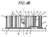
- a fire sensor according to a second embodiment of the present invention will be described with reference to Figs. 4A and 4B .
- the penetration space C belonging to the smoke sensing space A of the optical base 4 is arranged at the side of the narrow region R existing between the light emission platform portion 8b and the light reception platform portion 9b and not including the smoke sensing region B where smoke is sensed by the light emitting unit 8 and the light receiving unit 9.
- the penetration space C for the thermistor 3a to pass through is formed in the peripheral wall 83 extending along the irradiation direction of the light emission platform portion 8b and facing toward the narrow region R of the smoke sensing space A.
- the thermistor 3a is installed upright on the circuit board 3 and is arranged to pass through the through-hole 15 and to protrude beyond the optical base 4.
- about one half of the volume of the through-hole 15 is included in the light emission platform portion 8b.
- the labyrinth walls 13 are formed to have a substantially L-like cross section, thereby simplifying the configuration of the labyrinth walls 13.
- the narrow region R of the smoke sensing space A refers to a region which exists between the light emission platform portion 8b and the light reception platform portion 9b when seen from the plan-view intersection point P of the optical axes 80 and 90 of the light emitting unit 8 and the light receiving unit 9 and which does not include the smoke sensing region B.
- a light shield wall 14 is positioned in the narrow region R.
- the optical base 4 includes a cylindrical raised bottom platform 16 formed in the light emission platform portion 8b.
- the raised bottom platform 16 lifts up the bottom portion of the through-hole 15 in order to mount the circuit parts such as the thermistor 3a and the like to the circuit board 3.
- the through-hole 15 is integrally formed with the raised bottom platform 16.
- the support pole of the thermistor 3a is mounted to the circuit board 3 within the raised bottom platform 16 and is inserted into the through-hole 15 through the raised bottom platform 16.
- the peripheral wall 83 in which the through-hole 15 is formed is provided to face toward the narrow region R of the smoke sensing space A. For that reason, when seen from the smoke sensing region B, the position of the protrusion portion 83a of the peripheral wall 83 partially protruding due to the existence of the through-hole 15 is hidden behind the block of the light emission platform portion 8b. Accordingly, the light becoming a noise is less likely to reach the protrusion portion 83a. Even if the light reaches the protrusion portion 83a, the light is attenuated by the repeated reflection before arriving at the light emission platform portion 8b.
- the protrusion portion 83a is arranged in a position where the light arrives with attenuated intensity. This reduces the optical adverse affect on the protrusion portion 83a. Accordingly, the light receiving unit 9 is prevented from sensing the light other than the scattered light by smoke in the smoke sensing region B. It is therefore possible to avoid an erroneous operation otherwise caused by the superficial increase of the smoke particles attributable to the noise light. This makes it possible to increase the smoke sensing accuracy and reliability.
- the raised bottom platform 16 is provided to arrange the circuit parts such as the heat sensor and the like, the intensity of the scattered light arriving at the raised bottom platform 16 is attenuated and reduced. This reduces the optical affect of the raised bottom platform 16 as set forth above. In other words, the scattered light from the raised bottom platform 16 is not incident on the light receiving unit 9. Even when the scattered light from the raised bottom platform 16 is incident on the light receiving unit 9, the intensity of the scattered light is sufficiently attenuated. Thus, the scattered light from the raised bottom platform 16 has no optical affect.
- the penetration space C for the thermistor 3a to pass through is arranged in the light emission platform portion 8b.
- the penetration space C may be arranged in the light reception platform portion 9b.
- the penetration space C may be provided in both of the light emission platform portion 8b and the light reception platform portion 9b, and heat sensors having different temperature sensing levels may be arranged to pass through the respective penetration spaces C.
- the sensor passing through the penetration space C is not limited to the heat sensor but may be other environment measuring sensors such as a gas sensor and a humidity sensor.
Landscapes
- Physics & Mathematics (AREA)
- General Physics & Mathematics (AREA)
- Chemical & Material Sciences (AREA)
- Emergency Management (AREA)
- Business, Economics & Management (AREA)
- Analytical Chemistry (AREA)
- Health & Medical Sciences (AREA)
- Life Sciences & Earth Sciences (AREA)
- Biochemistry (AREA)
- General Health & Medical Sciences (AREA)
- Immunology (AREA)
- Pathology (AREA)
- Fire-Detection Mechanisms (AREA)
- Investigating Or Analysing Materials By Optical Means (AREA)
Description
- The present invention relates to a fire sensor for detecting a fire by sensing smoke and heat.
- As the conventional fire sensor, there is known a fire sensor in which a thermistor installed upright on a substrate is arranged to extend through a smoke sensing space, thereby sensing a temperature (see, e.g., Patent Document 1).
- One example of the conventional fire sensor is shown in
Fig. 5 . Afire sensor 100 includes asmoke sensing chamber 101 around which a plurality oflabyrinth walls 102 is installed, alight emitting unit 103 for irradiating light into a smoke sensing space A of thesmoke sensing chamber 101, alight receiving unit 104 arranged in a position where thelight receiving unit 104 does not directly receive the light irradiated from thelight emitting unit 103, and athermistor 105. Alight shield wall 106 for shielding the light irradiated from thelight emitting unit 103 to thelight receiving unit 104 without being scattered by smoke is installed upright in the smoke sensing space A. The region where the field of view seen from thelight emitting unit 103 and the field of view seen from thelight receiving unit 104 intersect each other becomes a smoke sensing region B. The light scattered by smoke in the smoke sensing region B is detected by thelight receiving unit 104, thereby sensing the smoke. A through-hole 107 is formed in thelight shield wall 106. Thethermistor 105 is inserted into the through-hole 107. Thethermistor 105 is installed upright on a substrate lying below thesmoke sensing chamber 101 and is configured to detect a temperature. - [Patent Document 1] Japanese Patent Application Publication No.
11-185179 - In the fire sensor disclosed in
Patent Document 1, the support member of the thermistor directly passes through the substantially central region of the smoke sensing space. Therefore, it is sometimes the case that the flow of smoke toward the smoke sensing space is hindered or the light is scattered. In thefire sensor 100 shown inFig. 5 , the volume of thelight shield wall 106 is increased and the flow of smoke from the gaps between thelabyrinth walls 102 toward the smoke sensing space A is inhibited. For that reason, it is often the case that the sensitivity of smoke sensing in the smoke sensing region is reduced and the response is delayed. -
EP 2 109 085 A2 -
EP 1 253 566 A2 - In view of the problems noted above, it is an object of the present invention to provide a fire sensor including a heat sensor extending through a smoke sensing space, which is capable of suppressing the reduction of the smoke sensing sensitivity and response delay otherwise caused by the arrangement of the heat sensor.
- In accordance with the present invention, there is provided a fire sensor, inter alia including: a plurality of labyrinth walls installed along a circumferential direction so as to surround a smoke sensing space; a light emitting unit arranged to irradiate light toward the smoke sensing space; a light receiving unit arranged in a position where the light receiving unit does not directly receive the light emitted from the light emitting unit; and a heat sensor, wherein the smoke sensing space includes a smoke sensing region defined by a light emission zone extending from the light emitting unit and a light reception zone extending from the light receiving unit, the fire sensor configured to detect a fire when the light receiving unit receives the scattered light of the light emitting unit generated in the smoke sensing region by smokes introduced into the smoke sensing space through gaps between the labyrinth walls, and wherein a penetration space is formed by a housing making up the light emitting unit or the light receiving unit, the penetration space separated from the smoke sensing space, the penetration space extending through the housing from the side of a housing mounting board to which the housing is mounted toward a detection target space, the heat sensor inserted into the penetration space, wherein the penetration space is arranged in a light emission platform portion for accommodating the light emitting unit or in a light reception platform portion for accommodating the light receiving unit.
- In the object detection device, a narrow region existing between the light emitting unit and the light receiving unit and not including the smoke sensing region is defined in the smoke sensing space, the penetration space arranged in the narrow region.
- According to the fire sensor of the present invention, the penetration space for the heat sensor to pass through is defined by the housing of the light emitting unit or the light receiving unit. It is therefore possible to reduce the volume defining the penetration space, to reduce the obstruction of the flow of an air into the smoke sensing space and to suppress the reduction of the smoke sensing sensitivity and response delay.
- Objects and features of the present invention will become more apparent from the following description of preferred embodiments given in conjunction with the accompanying drawings.
-
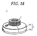
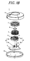
Fig. 1A is an outer appearance view of a fire sensor according to a first embodiment of the present invention andFig. 1B is an exploded perspective view of the fire sensor. -
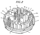
Fig. 2 is a perspective view of an optical base of the fire sensor. -
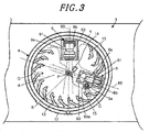
Fig. 3 is a bottom plan view of the optical base of the fire sensor installed on a ceiling surface. -
Fig. 4A is a plan view of an optical base of a fire sensor according to a second embodiment of the present invention andFig. 4B is a section view taken along line X-X inFig. 4A . -
Fig. 5 is a plan view of a smoke sensing chamber of a conventional fire sensor. - Embodiments of the present invention will now be described in detail with reference to the accompanying drawings which form a part hereof. Throughout the drawings, identical or similar parts will be designated by like reference symbols with no redundant description made thereon.
- A fire sensor according to a first embodiment of the present invention will be described with reference to
Figs. 1A to 3 . The fire sensor of the present embodiment is a complex type sensor having a smoke sensing function of a smoke sensor and a heat sensing function of a heat sensor. The fire sensor is a device that generates a fire alarm if a smoke sensing level or a heat sensing level exceeds a predetermined threshold value. As shown inFig. 1A , the outer shell of thefire sensor 1 includes a resin-madebody 2 attachable to a ceiling surface or the like and asensor cover 7. Thebody 2 is formed of abase 2a and acover 2b. In the perspective views ofFigs. 1A ,1B and2 , the fire sensor is shown in an upside-down state. The lower side of thefire sensor 1 on the drawing sheet is attached to a ceiling surface or the like. - The internal structure of, the
fire sensor 1 will be described with reference toFig. 1B . Thefire sensor 1 includes acircuit board 3 for mounting circuit parts, a smoke sensingoptical base 4 mounted to thecircuit board 3, a bug-proof cover 5 and aspeaker 6, all of which are accommodated within thesensor cover 7 and thecover 2b. - The
sensor cover 7 accommodates theoptical base 4, the bug-proof cover 5 and thespeaker 6 therein and serves as a protection cover for protecting theoptical base 4, the bug-proof cover 5 and thespeaker 6. Thesensor cover 7 is formed into a closed-bottom cylindrical shape. A plurality of hull support portions and a plurality of opening portions are alternately formed on the side surface of thesensor cover 7. Smoke infiltrates from the outside into a smoke sensing space existing above theoptical base 4 through the opening portions of thesensor cover 7 and the apertures of an insect screen of the bug-proof cover 5. - The
base 2a is made of a resin and is formed into a substantially disc-like shape. Two screw holes are formed on the installation surface of thebase 2a so that thebase 2a can be screw-fixed to, e.g., a ceiling surface. Thecover 2b accommodates parts of thefire sensor 1 therein. Thecover 2b is coupled to thebase 2a by rotating thecover 2b clockwise while moving thecover 2b toward thebase 2a. Thesensor cover 7 and thecover 2b are each formed of a metal portion as a core member and an insulating resin coated on the metal portion. - The bug-
proof cover 5 is of a structure having an insect screen for preventing bugs or dirt from entering a smoke sensing region. The bug-proof cover 5 is configured so that the lower end portion thereof can be fitted to the peripheral wall of theoptical base 4. Thespeaker 6 is fitted to the upper surface of the bug-proof cover 5. Thespeaker 6 has a function of generating an alarm sound for the notification of fire sensing. In the fire sensor, a narrow region existing between a light emitting unit and a light receiving unit and not including the smoke sensing region is defined in the smoke sensing space. It is preferred that a penetration space is arranged in the narrow region. - A resin-made printed board, a ceramic board or the like is used as the
circuit board 3. Thecircuit board 3 includes thelight emitting unit 8 and thelight receiving unit 9. Thelight emitting unit 8 is provided with anLED 8a that irradiates light for sensing smoke. Thelight receiving unit 9 is provided with a PD (Photo Diode) 9a for sensing the light emitted from theLED 8a and scattered by smoke. Thecircuit board 3 further includes a heat sensor, e.g., athermistor 3a, and a circuit part, e.g., a microcomputer for outputting a fire alarm signal on the basis of a smoke sensing signal from thelight receiving unit 9 and a heat sensing signal from thethermistor 3a. - The
optical base 4 includes a lightemission platform portion 8b and a lightreception platform portion 9b for accommodating theLED 8a and thePD 9a, respectively. A through-hole 15 (seeFig. 2 ) for defining a penetration space C through which thethermistor 3a passes is integrally formed in the lightemission platform portion 8b. Thethermistor 3a includes a thermistor element portion arranged at the tip end of a lead electrically connected to thecircuit board 3. Thethermistor 3a is mounted upright on the part mounting surface of thecircuit board 3. - The
LED 8a is accommodated within the lightemission platform portion 8b of theoptical base 4 from the bottom surface side thereof. ThePD 9a is accommodated within the lightreception platform portion 9b. Thethermistor 3a is mounted so as to pass through the penetration space C. Thethermistor 3a protrudes from thecircuit board 3 through theoptical base 4. Thethermistor 3a is mounted so that the thermistor element portion thereof can be spaced apart from thecircuit board 3. - The detailed configuration of the
optical base 4 will be further described. As shown inFig. 2 , theoptical base 4 has a closed-bottom cylindrical shape and includes a substantially disc-shapedbottom plate 11, aperipheral wall 12 installed to protrude from thebottom plate 11 and a plurality oflabyrinth walls 13 installed upright on thebottom plate 11 and arranged along theperipheral wall 12. Thebottom plate 11, theperipheral wall 12 and thelabyrinth walls 13 are integrally formed with the lightemission platform portion 8b and the lightreception platform portion 9b. Theoptical base 4 may be made of a black synthetic resin in order to restrain the light from being reflected by the respective portions including thelabyrinth walls 13. - The
labyrinth walls 13 are formed of partition walls having a substantially F-like horizontal cross section. Thelabyrinth walls 13 are arranged along the circumferential direction to define a smoke sensing area having a circular horizontal cross section on theoptical base 4. The smoke sensing area defines a smoke sensing space A for detecting the smoke infiltrated from the outside. Smoke introduction paths are formed between thelabyrinth walls 13 adjoining one another. One ends of the smoke introduction paths become smoke introduction ports communicating with the outside and the other ends of the smoke introduction paths communicate with the smoke sensing space A. In this regard, the F-like curved protrusions of thelabyrinth walls 13 prevent external light from directly entering the smoke sensing space A through the smoke introduction paths. - The light
emission platform portion 8b and the lightreception platform portion 9b are formed in a platform shape to protrude from thebottom plate 11 of theoptical base 4 toward the smoke sensing space A of theoptical base 4. The lightemission platform portion 8b and the lightreception platform portion 9b have through-holes LED 8a and thePD 9a. Grooves connected to the through-holes emission platform portion 8b and the lightreception platform portion 9b. The lightemission platform portion 8b and the lightreception platform portion 9b includeperipheral walls holes holes emission platform portion 8b and the lightreception platform portion 9b. The optical axes of the respective lenses extend toward the center of the smoke sensing space A and intersect each other at a predetermined angle. The lenses face toward the light emission surface of theLED 8a and the light reception surface of thePD 9a. The light emitted from theLED 8a is collected by the lense to be irradiated into the smoke sensing space A. - The through-
hole 15 is formed in the lightemission platform portion 8b to extend from thecircuit board 3 toward a detection target space (room). The through-hole 15 is defined within aprotrusion portion 83a formed by partially bulging theperipheral wall 83 of the lightemission platform portion 8b. Accordingly, about one half of the volume of the through-hole 15 is included in the lightemission platform portion 8b. The through-hole 15 may be formed in other portions than theperipheral wall 83 as long as the through-hole 15 is integrally formed with the lightemission platform portion 8b. Instead of changing the external shape of the lightemission platform portion 8b, the through-hole 15 as a whole may be included in the lightemission platform portion 8b. - As shown in
Fig. 3 , thecircuit board 3 is attached to the lightemission platform portion 8b and the lightreception platform portion 9b of theoptical base 4 in a state that the optical parts such as the lenses and the like are attached thereto. Thus, theLED 8a and thePD 9a are arranged within the lightemission platform portion 8b and the lightreception platform portion 9b. At this time, thethermistor 3a passes through the through-hole 15 of the lightemission platform portion 8b and can extend to the vicinity of the upper surface of thesensor cover 7. Thethermistor 3a is arranged in a position where thethermistor 3a can easily sense the heat generated by smoke or the like. - The light
emission platform portion 8b and the lightreception platform portion 9b are formed such that the plan-view intersection point P of anoptical axis 80 of the light emission surface and anoptical axis 90 of the light reception surface thereof is positioned at the center of the smoke sensing space A. In the smoke sensing space A surrounded by thelabyrinth walls 13, the region where the emission zone of the light emitted from thelight emitting unit 8 of the lightemission platform portion 8b overlaps with the reception zone of the light received by thelight receiving unit 9 of the lightreception platform portion 9b will be referred to as a smoke sensing region B. The scattered light generated in the smoke sensing region B when the light coming from theLED 8a accommodated in the lightemission platform portion 8b is scattered by the particles of smoke, is sensed with high sensitivity by thePD 9a accommodated in the lightreception platform portion 9b. - In the smoke sensing space A, there are formed a narrow region R existing between the light
emission platform portion 8b and the lightreception platform portion 9b and not including the smoke sensing region B and a wide region Q excluding the narrow region R and including the smoke sensing region B. The narrow region R is a region narrower than the wide region Q. In a plan view, the narrow region R exists between the lightemission platform portion 8b and the lightreception platform portion 9b in the 360 degree directions about the intersection point P of theoptical axes light emitting unit 8 and thelight receiving unit 9. The narrow region R does not include the smoke sensing region B. The through-hole 15 of the lightemission platform portion 8b is positioned in theperipheral wall 83 facing toward the wide region Q where the through-hole 15 can be easily arranged. - According to the present embodiment, the penetration space C for the
thermistor 3a to pass through is integrally formed with the lightemission platform portion 8b. It is therefore possible to reduce the volume defining the penetration space C, to reduce the obstruction of the flow of an air into the smoke sensing space A and to suppress the reduction of the smoke sensing sensitivity and response delay. - A fire sensor according to a second embodiment of the present invention will be described with reference to
Figs. 4A and4B . In the present embodiment, unlike the first embodiment, the penetration space C belonging to the smoke sensing space A of theoptical base 4 is arranged at the side of the narrow region R existing between the lightemission platform portion 8b and the lightreception platform portion 9b and not including the smoke sensing region B where smoke is sensed by thelight emitting unit 8 and thelight receiving unit 9. - In the
optical base 4 of the present embodiment, the penetration space C for thethermistor 3a to pass through is formed in theperipheral wall 83 extending along the irradiation direction of the lightemission platform portion 8b and facing toward the narrow region R of the smoke sensing space A. As mentioned above, thethermistor 3a is installed upright on thecircuit board 3 and is arranged to pass through the through-hole 15 and to protrude beyond theoptical base 4. In this case, as set forth above, about one half of the volume of the through-hole 15 is included in the lightemission platform portion 8b. Thelabyrinth walls 13 are formed to have a substantially L-like cross section, thereby simplifying the configuration of thelabyrinth walls 13. - As stated above, the narrow region R of the smoke sensing space A refers to a region which exists between the light
emission platform portion 8b and the lightreception platform portion 9b when seen from the plan-view intersection point P of theoptical axes light emitting unit 8 and thelight receiving unit 9 and which does not include the smoke sensing region B. Alight shield wall 14 is positioned in the narrow region R. - The
optical base 4 includes a cylindrical raisedbottom platform 16 formed in the lightemission platform portion 8b. The raisedbottom platform 16 lifts up the bottom portion of the through-hole 15 in order to mount the circuit parts such as thethermistor 3a and the like to thecircuit board 3. The through-hole 15 is integrally formed with the raisedbottom platform 16. The support pole of thethermistor 3a is mounted to thecircuit board 3 within the raisedbottom platform 16 and is inserted into the through-hole 15 through the raisedbottom platform 16. - According to the present embodiment, in the light
emission platform portion 8b, theperipheral wall 83 in which the through-hole 15 is formed is provided to face toward the narrow region R of the smoke sensing space A. For that reason, when seen from the smoke sensing region B, the position of theprotrusion portion 83a of theperipheral wall 83 partially protruding due to the existence of the through-hole 15 is hidden behind the block of the lightemission platform portion 8b. Accordingly, the light becoming a noise is less likely to reach theprotrusion portion 83a. Even if the light reaches theprotrusion portion 83a, the light is attenuated by the repeated reflection before arriving at the lightemission platform portion 8b. Theprotrusion portion 83a is arranged in a position where the light arrives with attenuated intensity. This reduces the optical adverse affect on theprotrusion portion 83a. Accordingly, thelight receiving unit 9 is prevented from sensing the light other than the scattered light by smoke in the smoke sensing region B. It is therefore possible to avoid an erroneous operation otherwise caused by the superficial increase of the smoke particles attributable to the noise light. This makes it possible to increase the smoke sensing accuracy and reliability. - Even if the raised
bottom platform 16 is provided to arrange the circuit parts such as the heat sensor and the like, the intensity of the scattered light arriving at the raisedbottom platform 16 is attenuated and reduced. This reduces the optical affect of the raisedbottom platform 16 as set forth above. In other words, the scattered light from the raisedbottom platform 16 is not incident on thelight receiving unit 9. Even when the scattered light from the raisedbottom platform 16 is incident on thelight receiving unit 9, the intensity of the scattered light is sufficiently attenuated. Thus, the scattered light from the raisedbottom platform 16 has no optical affect. - The present invention is not limited to the configurations of the embodiments described above and may be modified in many different forms without departing from scope of the invention. For example, in the respective embodiments described above, the penetration space C for the
thermistor 3a to pass through is arranged in the lightemission platform portion 8b. However, the penetration space C may be arranged in the lightreception platform portion 9b. The penetration space C may be provided in both of the lightemission platform portion 8b and the lightreception platform portion 9b, and heat sensors having different temperature sensing levels may be arranged to pass through the respective penetration spaces C. The sensor passing through the penetration space C is not limited to the heat sensor but may be other environment measuring sensors such as a gas sensor and a humidity sensor. - While the preferred embodiments of the present invention have been described above, the present invention is not limited to these specific embodiments but can be changed or modified in many different forms without departing from the scope of the claims. Such changes or modifications shall be construed to fall within the scope of the present invention.
Claims (2)
- A fire sensor (1), comprising:a plurality of labyrinth walls (13) installed along a circumferential direction so as to surround a smoke sensing space (A);a light emitting unit (8) arranged to irradiate light toward the smoke sensing space (A);a light receiving unit (9) arranged in a position where the light receiving unit (9) does not directly receive the light emitted from the light emitting unit (8); anda heat sensor (3a),wherein the smoke sensing space (A) includes a smoke sensing region (B) defined by a light emission zone extending from the light emitting unit (8) and a light reception zone extending from the light receiving unit (9), the fire sensor (1) configured to detect a fire when the light receiving unit (9) receives the scattered light of the light emitting unit (8) generated in the smoke sensing region (B) by smokes introduced into the smoke sensing space (A) through gaps between the labyrinth walls (13),wherein a penetration space (C) is formed by a housing (4, 8b) making up the light emitting unit (8) or the light receiving unit (9), the penetration space (C) separated from the smoke sensing space (A), the penetration space (C) extending through the housing (4, 8b) from the side of a housing mounting board (3) to which the housing (4) is mounted toward a detection target space, the heat sensor (3a) inserted into the penetration space (C), characterized in thatthe penetration space (C) is arranged in a light emission platform portion (8b) for accommodating the light emitting unit (8) or in a light reception platform portion (9b) for accommodating the light receiving unit (9).
- The fire sensor of claim 1, wherein a narrow region (R) existing between the light emitting unit (8) and the light receiving unit (9) and not including the smoke sensing region (B) is defined in the smoke sensing space (A), the penetration space (C) arranged in the narrow region (R).
Applications Claiming Priority (2)
| Application Number | Priority Date | Filing Date | Title |
|---|---|---|---|
| JP2011053914A JP5853143B2 (en) | 2011-03-11 | 2011-03-11 | Fire detector |
| PCT/IB2012/000442 WO2012123796A1 (en) | 2011-03-11 | 2012-03-09 | Fire sensor |
Publications (3)
| Publication Number | Publication Date |
|---|---|
| EP2685437A1 EP2685437A1 (en) | 2014-01-15 |
| EP2685437A4 EP2685437A4 (en) | 2014-09-03 |
| EP2685437B1 true EP2685437B1 (en) | 2016-02-03 |
Family
ID=46830096
Family Applications (1)
| Application Number | Title | Priority Date | Filing Date |
|---|---|---|---|
| EP12758282.3A Active EP2685437B1 (en) | 2011-03-11 | 2012-03-09 | Fire sensor |
Country Status (5)
| Country | Link |
|---|---|
| EP (1) | EP2685437B1 (en) |
| JP (1) | JP5853143B2 (en) |
| DK (1) | DK2685437T3 (en) |
| TW (1) | TWI439968B (en) |
| WO (1) | WO2012123796A1 (en) |
Cited By (3)
| Publication number | Priority date | Publication date | Assignee | Title |
|---|---|---|---|---|
| US11195399B2 (en) | 2017-09-06 | 2021-12-07 | Carrier Corporation | Heat alarm unit |
| US11430313B2 (en) | 2018-05-31 | 2022-08-30 | Autronica Fire & Security As | Printed circuit board for smoke detector |
| US11790746B2 (en) | 2021-02-02 | 2023-10-17 | Carrier Corporation | Smoke entry solution for multi wave multi angle safety device |
Families Citing this family (16)
| Publication number | Priority date | Publication date | Assignee | Title |
|---|---|---|---|---|
| JP5640247B2 (en) * | 2012-08-31 | 2014-12-17 | 日本フェンオール株式会社 | Photoelectric smoke detector and suction smoke detection system |
| US9098988B2 (en) * | 2012-12-18 | 2015-08-04 | Excelitas Technologies Philippines Inc. | Integrated smoke cell |
| CN103400469A (en) * | 2013-07-31 | 2013-11-20 | 武光杰 | Smoke module |
| GB2517917A (en) * | 2013-09-04 | 2015-03-11 | Sprue Safety Products Ltd | Heat detector |
| CN204390398U (en) * | 2014-10-14 | 2015-06-10 | 宁波尚泰电子有限公司 | Smoke alarm |
| JP6568725B2 (en) * | 2015-06-11 | 2019-08-28 | 能美防災株式会社 | Fire detector |
| WO2017073582A1 (en) * | 2015-10-28 | 2017-05-04 | ホーチキ株式会社 | Equipment-mounting structure, mounting plate for same, alarm unit, fire alarm unit, alarm device, and method for manufacturing same |
| US10769921B2 (en) | 2016-08-04 | 2020-09-08 | Carrier Corporation | Smoke detector |
| KR101777558B1 (en) * | 2016-08-10 | 2017-09-12 | 주식회사 파워웰 | Fire alarm for Wireless alert transmission |
| JP7329116B2 (en) * | 2018-05-30 | 2023-08-17 | 能美防災株式会社 | Smoke detectors |
| KR101947966B1 (en) * | 2018-08-16 | 2019-02-13 | 김도연 | Apparatus for safety shutoff of gas valve |
| JP7531095B2 (en) * | 2018-10-10 | 2024-08-09 | パナソニックIpマネジメント株式会社 | Sensor |
| US11846588B2 (en) * | 2019-11-27 | 2023-12-19 | Xuedan WU | Detection component of the photoelectric smoke detection fire alarm |
| KR102565619B1 (en) * | 2021-11-16 | 2023-08-14 | 주식회사 투에스텍 | Fire dedecting module |
| US12437622B2 (en) | 2022-03-04 | 2025-10-07 | Kidde Fire Protection, Llc | Smoke alarm with offset detection chamber and shield |
| JP2026067754A (en) * | 2024-10-09 | 2026-04-21 | パナソニックIpマネジメント株式会社 | Smoke detection device, sensor device, and sensor system |
Family Cites Families (9)
| Publication number | Priority date | Publication date | Assignee | Title |
|---|---|---|---|---|
| JPH11185179A (en) | 1997-12-18 | 1999-07-09 | Matsushita Electric Works Ltd | Heat and smoke combined type fire sensor and manufacture thereof |
| IT1315417B1 (en) * | 2000-04-11 | 2003-02-10 | Pittway Tecnologica Spa | FIRE DETECTOR STRUCTURE |
| JP3823739B2 (en) * | 2001-02-23 | 2006-09-20 | 松下電工株式会社 | Fire detector |
| TWI235965B (en) * | 2001-04-24 | 2005-07-11 | Matsushita Electric Works Ltd | Fire detector unit |
| JP3979032B2 (en) * | 2001-05-28 | 2007-09-19 | 松下電工株式会社 | Fire detector |
| JP2003067862A (en) * | 2001-08-28 | 2003-03-07 | Matsushita Electric Works Ltd | Compound fire sensor |
| DE10246756B4 (en) * | 2002-10-07 | 2006-03-16 | Novar Gmbh | Fire detection procedure and fire detector for its implementation |
| JP4668702B2 (en) * | 2005-06-30 | 2011-04-13 | ニッタン株式会社 | Fire detector |
| CN102436712B (en) * | 2008-03-31 | 2014-10-15 | 能美防灾株式会社 | Combination smoke and heat detector |
-
2011
- 2011-03-11 JP JP2011053914A patent/JP5853143B2/en active Active
-
2012
- 2012-03-09 DK DK12758282.3T patent/DK2685437T3/en active
- 2012-03-09 EP EP12758282.3A patent/EP2685437B1/en active Active
- 2012-03-09 TW TW101107992A patent/TWI439968B/en active
- 2012-03-09 WO PCT/IB2012/000442 patent/WO2012123796A1/en not_active Ceased
Cited By (3)
| Publication number | Priority date | Publication date | Assignee | Title |
|---|---|---|---|---|
| US11195399B2 (en) | 2017-09-06 | 2021-12-07 | Carrier Corporation | Heat alarm unit |
| US11430313B2 (en) | 2018-05-31 | 2022-08-30 | Autronica Fire & Security As | Printed circuit board for smoke detector |
| US11790746B2 (en) | 2021-02-02 | 2023-10-17 | Carrier Corporation | Smoke entry solution for multi wave multi angle safety device |
Also Published As
| Publication number | Publication date |
|---|---|
| JP2012190306A (en) | 2012-10-04 |
| TW201237810A (en) | 2012-09-16 |
| EP2685437A1 (en) | 2014-01-15 |
| JP5853143B2 (en) | 2016-02-09 |
| DK2685437T3 (en) | 2016-04-11 |
| TWI439968B (en) | 2014-06-01 |
| WO2012123796A1 (en) | 2012-09-20 |
| EP2685437A4 (en) | 2014-09-03 |
Similar Documents
| Publication | Publication Date | Title |
|---|---|---|
| DK2685437T3 (en) | Fire sensor | |
| EP2936464B1 (en) | Integrated smoke cell | |
| EP2561496B1 (en) | Smoke detector | |
| TWI442346B (en) | Photoelectric smoke detector | |
| CN100449573C (en) | fire alarm | |
| KR100453489B1 (en) | Fire detector unit | |
| JP5660794B2 (en) | Photoelectric smoke detector | |
| EP3884477B1 (en) | Smoke detector | |
| JP7728917B2 (en) | thermal alarm | |
| EP1146492B1 (en) | Multi-sensor | |
| JP2009245102A (en) | Combination smoke and heat detector | |
| JP2010238095A (en) | Photoelectric smoke sensor | |
| JP2009245110A (en) | Combination smoke and heat detector | |
| JP2010086378A (en) | Photoelectric smoke detector | |
| JP7157557B2 (en) | Smoke detectors | |
| JP2011192245A (en) | Heat and smoke compound type fire sensor | |
| JP2021174121A (en) | sensor | |
| JP7553666B2 (en) | Smoke detectors | |
| JP4999812B2 (en) | Fire alarm | |
| JP2023166064A (en) | Smoke sensor | |
| JP2020046807A (en) | Fire detector |
Legal Events
| Date | Code | Title | Description |
|---|---|---|---|
| PUAI | Public reference made under article 153(3) epc to a published international application that has entered the european phase |
Free format text: ORIGINAL CODE: 0009012 |
|
| 17P | Request for examination filed |
Effective date: 20130909 |
|
| AK | Designated contracting states |
Kind code of ref document: A1 Designated state(s): AL AT BE BG CH CY CZ DE DK EE ES FI FR GB GR HR HU IE IS IT LI LT LU LV MC MK MT NL NO PL PT RO RS SE SI SK SM TR |
|
| DAX | Request for extension of the european patent (deleted) | ||
| A4 | Supplementary search report drawn up and despatched |
Effective date: 20140801 |
|
| RIC1 | Information provided on ipc code assigned before grant |
Ipc: G08B 17/10 20060101ALI20140728BHEP Ipc: G08B 17/107 20060101AFI20140728BHEP Ipc: G08B 17/06 20060101ALI20140728BHEP Ipc: G01N 21/53 20060101ALI20140728BHEP |
|
| RAP1 | Party data changed (applicant data changed or rights of an application transferred) |
Owner name: PANASONIC INTELLECTUAL PROPERTY MANAGEMENT CO., LT |
|
| GRAP | Despatch of communication of intention to grant a patent |
Free format text: ORIGINAL CODE: EPIDOSNIGR1 |
|
| INTG | Intention to grant announced |
Effective date: 20150814 |
|
| GRAS | Grant fee paid |
Free format text: ORIGINAL CODE: EPIDOSNIGR3 |
|
| GRAA | (expected) grant |
Free format text: ORIGINAL CODE: 0009210 |
|
| AK | Designated contracting states |
Kind code of ref document: B1 Designated state(s): AL AT BE BG CH CY CZ DE DK EE ES FI FR GB GR HR HU IE IS IT LI LT LU LV MC MK MT NL NO PL PT RO RS SE SI SK SM TR |
|
| REG | Reference to a national code |
Ref country code: GB Ref legal event code: FG4D |
|
| REG | Reference to a national code |
Ref country code: AT Ref legal event code: REF Ref document number: 774013 Country of ref document: AT Kind code of ref document: T Effective date: 20160215 Ref country code: CH Ref legal event code: EP |
|
| REG | Reference to a national code |
Ref country code: IE Ref legal event code: FG4D |
|
| REG | Reference to a national code |
Ref country code: DE Ref legal event code: R096 Ref document number: 602012014435 Country of ref document: DE |
|
| REG | Reference to a national code |
Ref country code: DK Ref legal event code: T3 Effective date: 20160405 |
|
| REG | Reference to a national code |
Ref country code: SE Ref legal event code: TRGR |
|
| REG | Reference to a national code |
Ref country code: NO Ref legal event code: T2 Effective date: 20160203 |
|
| REG | Reference to a national code |
Ref country code: LT Ref legal event code: MG4D Ref country code: NL Ref legal event code: MP Effective date: 20160203 |
|
| REG | Reference to a national code |
Ref country code: AT Ref legal event code: MK05 Ref document number: 774013 Country of ref document: AT Kind code of ref document: T Effective date: 20160203 |
|
| PG25 | Lapsed in a contracting state [announced via postgrant information from national office to epo] |
Ref country code: IT Free format text: LAPSE BECAUSE OF FAILURE TO SUBMIT A TRANSLATION OF THE DESCRIPTION OR TO PAY THE FEE WITHIN THE PRESCRIBED TIME-LIMIT Effective date: 20160203 Ref country code: HR Free format text: LAPSE BECAUSE OF FAILURE TO SUBMIT A TRANSLATION OF THE DESCRIPTION OR TO PAY THE FEE WITHIN THE PRESCRIBED TIME-LIMIT Effective date: 20160203 Ref country code: ES Free format text: LAPSE BECAUSE OF FAILURE TO SUBMIT A TRANSLATION OF THE DESCRIPTION OR TO PAY THE FEE WITHIN THE PRESCRIBED TIME-LIMIT Effective date: 20160203 Ref country code: GR Free format text: LAPSE BECAUSE OF FAILURE TO SUBMIT A TRANSLATION OF THE DESCRIPTION OR TO PAY THE FEE WITHIN THE PRESCRIBED TIME-LIMIT Effective date: 20160504 |
|
| PG25 | Lapsed in a contracting state [announced via postgrant information from national office to epo] |
Ref country code: IS Free format text: LAPSE BECAUSE OF FAILURE TO SUBMIT A TRANSLATION OF THE DESCRIPTION OR TO PAY THE FEE WITHIN THE PRESCRIBED TIME-LIMIT Effective date: 20160603 Ref country code: RS Free format text: LAPSE BECAUSE OF FAILURE TO SUBMIT A TRANSLATION OF THE DESCRIPTION OR TO PAY THE FEE WITHIN THE PRESCRIBED TIME-LIMIT Effective date: 20160203 Ref country code: PL Free format text: LAPSE BECAUSE OF FAILURE TO SUBMIT A TRANSLATION OF THE DESCRIPTION OR TO PAY THE FEE WITHIN THE PRESCRIBED TIME-LIMIT Effective date: 20160203 Ref country code: BE Free format text: LAPSE BECAUSE OF NON-PAYMENT OF DUE FEES Effective date: 20160331 Ref country code: NL Free format text: LAPSE BECAUSE OF FAILURE TO SUBMIT A TRANSLATION OF THE DESCRIPTION OR TO PAY THE FEE WITHIN THE PRESCRIBED TIME-LIMIT Effective date: 20160203 Ref country code: LT Free format text: LAPSE BECAUSE OF FAILURE TO SUBMIT A TRANSLATION OF THE DESCRIPTION OR TO PAY THE FEE WITHIN THE PRESCRIBED TIME-LIMIT Effective date: 20160203 Ref country code: PT Free format text: LAPSE BECAUSE OF FAILURE TO SUBMIT A TRANSLATION OF THE DESCRIPTION OR TO PAY THE FEE WITHIN THE PRESCRIBED TIME-LIMIT Effective date: 20160603 Ref country code: AT Free format text: LAPSE BECAUSE OF FAILURE TO SUBMIT A TRANSLATION OF THE DESCRIPTION OR TO PAY THE FEE WITHIN THE PRESCRIBED TIME-LIMIT Effective date: 20160203 Ref country code: LV Free format text: LAPSE BECAUSE OF FAILURE TO SUBMIT A TRANSLATION OF THE DESCRIPTION OR TO PAY THE FEE WITHIN THE PRESCRIBED TIME-LIMIT Effective date: 20160203 |
|
| PG25 | Lapsed in a contracting state [announced via postgrant information from national office to epo] |
Ref country code: EE Free format text: LAPSE BECAUSE OF FAILURE TO SUBMIT A TRANSLATION OF THE DESCRIPTION OR TO PAY THE FEE WITHIN THE PRESCRIBED TIME-LIMIT Effective date: 20160203 |
|
| REG | Reference to a national code |
Ref country code: CH Ref legal event code: PL |
|
| REG | Reference to a national code |
Ref country code: DE Ref legal event code: R097 Ref document number: 602012014435 Country of ref document: DE |
|
| PG25 | Lapsed in a contracting state [announced via postgrant information from national office to epo] |
Ref country code: SK Free format text: LAPSE BECAUSE OF FAILURE TO SUBMIT A TRANSLATION OF THE DESCRIPTION OR TO PAY THE FEE WITHIN THE PRESCRIBED TIME-LIMIT Effective date: 20160203 Ref country code: CZ Free format text: LAPSE BECAUSE OF FAILURE TO SUBMIT A TRANSLATION OF THE DESCRIPTION OR TO PAY THE FEE WITHIN THE PRESCRIBED TIME-LIMIT Effective date: 20160203 Ref country code: RO Free format text: LAPSE BECAUSE OF FAILURE TO SUBMIT A TRANSLATION OF THE DESCRIPTION OR TO PAY THE FEE WITHIN THE PRESCRIBED TIME-LIMIT Effective date: 20160203 Ref country code: SM Free format text: LAPSE BECAUSE OF FAILURE TO SUBMIT A TRANSLATION OF THE DESCRIPTION OR TO PAY THE FEE WITHIN THE PRESCRIBED TIME-LIMIT Effective date: 20160203 |
|
| PLBE | No opposition filed within time limit |
Free format text: ORIGINAL CODE: 0009261 |
|
| STAA | Information on the status of an ep patent application or granted ep patent |
Free format text: STATUS: NO OPPOSITION FILED WITHIN TIME LIMIT |
|
| REG | Reference to a national code |
Ref country code: IE Ref legal event code: MM4A |
|
| PG25 | Lapsed in a contracting state [announced via postgrant information from national office to epo] |
Ref country code: BE Free format text: LAPSE BECAUSE OF FAILURE TO SUBMIT A TRANSLATION OF THE DESCRIPTION OR TO PAY THE FEE WITHIN THE PRESCRIBED TIME-LIMIT Effective date: 20160203 |
|
| REG | Reference to a national code |
Ref country code: FR Ref legal event code: ST Effective date: 20161130 |
|
| 26N | No opposition filed |
Effective date: 20161104 |
|
| GBPC | Gb: european patent ceased through non-payment of renewal fee |
Effective date: 20160503 |
|
| PG25 | Lapsed in a contracting state [announced via postgrant information from national office to epo] |
Ref country code: FR Free format text: LAPSE BECAUSE OF NON-PAYMENT OF DUE FEES Effective date: 20160404 Ref country code: IE Free format text: LAPSE BECAUSE OF NON-PAYMENT OF DUE FEES Effective date: 20160309 Ref country code: CH Free format text: LAPSE BECAUSE OF NON-PAYMENT OF DUE FEES Effective date: 20160331 Ref country code: LI Free format text: LAPSE BECAUSE OF NON-PAYMENT OF DUE FEES Effective date: 20160331 |
|
| PG25 | Lapsed in a contracting state [announced via postgrant information from national office to epo] |
Ref country code: SI Free format text: LAPSE BECAUSE OF FAILURE TO SUBMIT A TRANSLATION OF THE DESCRIPTION OR TO PAY THE FEE WITHIN THE PRESCRIBED TIME-LIMIT Effective date: 20160203 Ref country code: BG Free format text: LAPSE BECAUSE OF FAILURE TO SUBMIT A TRANSLATION OF THE DESCRIPTION OR TO PAY THE FEE WITHIN THE PRESCRIBED TIME-LIMIT Effective date: 20160503 |
|
| PG25 | Lapsed in a contracting state [announced via postgrant information from national office to epo] |
Ref country code: GB Free format text: LAPSE BECAUSE OF NON-PAYMENT OF DUE FEES Effective date: 20160503 |
|
| PG25 | Lapsed in a contracting state [announced via postgrant information from national office to epo] |
Ref country code: MT Free format text: LAPSE BECAUSE OF FAILURE TO SUBMIT A TRANSLATION OF THE DESCRIPTION OR TO PAY THE FEE WITHIN THE PRESCRIBED TIME-LIMIT Effective date: 20160203 |
|
| PG25 | Lapsed in a contracting state [announced via postgrant information from national office to epo] |
Ref country code: CY Free format text: LAPSE BECAUSE OF FAILURE TO SUBMIT A TRANSLATION OF THE DESCRIPTION OR TO PAY THE FEE WITHIN THE PRESCRIBED TIME-LIMIT Effective date: 20160203 Ref country code: HU Free format text: LAPSE BECAUSE OF FAILURE TO SUBMIT A TRANSLATION OF THE DESCRIPTION OR TO PAY THE FEE WITHIN THE PRESCRIBED TIME-LIMIT; INVALID AB INITIO Effective date: 20120309 |
|
| PG25 | Lapsed in a contracting state [announced via postgrant information from national office to epo] |
Ref country code: MK Free format text: LAPSE BECAUSE OF FAILURE TO SUBMIT A TRANSLATION OF THE DESCRIPTION OR TO PAY THE FEE WITHIN THE PRESCRIBED TIME-LIMIT Effective date: 20160203 Ref country code: LU Free format text: LAPSE BECAUSE OF NON-PAYMENT OF DUE FEES Effective date: 20160309 Ref country code: MC Free format text: LAPSE BECAUSE OF FAILURE TO SUBMIT A TRANSLATION OF THE DESCRIPTION OR TO PAY THE FEE WITHIN THE PRESCRIBED TIME-LIMIT Effective date: 20160203 Ref country code: MT Free format text: LAPSE BECAUSE OF FAILURE TO SUBMIT A TRANSLATION OF THE DESCRIPTION OR TO PAY THE FEE WITHIN THE PRESCRIBED TIME-LIMIT Effective date: 20160331 |
|
| PG25 | Lapsed in a contracting state [announced via postgrant information from national office to epo] |
Ref country code: AL Free format text: LAPSE BECAUSE OF FAILURE TO SUBMIT A TRANSLATION OF THE DESCRIPTION OR TO PAY THE FEE WITHIN THE PRESCRIBED TIME-LIMIT Effective date: 20160203 |
|
| PGFP | Annual fee paid to national office [announced via postgrant information from national office to epo] |
Ref country code: SE Payment date: 20260319 Year of fee payment: 15 |
|
| PGFP | Annual fee paid to national office [announced via postgrant information from national office to epo] |
Ref country code: NO Payment date: 20260323 Year of fee payment: 15 Ref country code: DK Payment date: 20260324 Year of fee payment: 15 Ref country code: DE Payment date: 20260319 Year of fee payment: 15 |
|
| PGFP | Annual fee paid to national office [announced via postgrant information from national office to epo] |
Ref country code: FI Payment date: 20260323 Year of fee payment: 15 |
|
| PGFP | Annual fee paid to national office [announced via postgrant information from national office to epo] |
Ref country code: TR Payment date: 20260303 Year of fee payment: 15 |