EP2685432A2 - Vehicle information management system - Google Patents
Vehicle information management system Download PDFInfo
- Publication number
- EP2685432A2 EP2685432A2 EP12192793.3A EP12192793A EP2685432A2 EP 2685432 A2 EP2685432 A2 EP 2685432A2 EP 12192793 A EP12192793 A EP 12192793A EP 2685432 A2 EP2685432 A2 EP 2685432A2
- Authority
- EP
- European Patent Office
- Prior art keywords
- abnormality
- data
- type
- vehicle
- storage
- Prior art date
- Legal status (The legal status is an assumption and is not a legal conclusion. Google has not performed a legal analysis and makes no representation as to the accuracy of the status listed.)
- Granted
Links
Images




Classifications
-
- G—PHYSICS
- G06—COMPUTING OR CALCULATING; COUNTING
- G06F—ELECTRIC DIGITAL DATA PROCESSING
- G06F17/00—Digital computing or data processing equipment or methods, specially adapted for specific functions
-
- B—PERFORMING OPERATIONS; TRANSPORTING
- B60—VEHICLES IN GENERAL
- B60Q—ARRANGEMENT OF SIGNALLING OR LIGHTING DEVICES, THE MOUNTING OR SUPPORTING THEREOF OR CIRCUITS THEREFOR, FOR VEHICLES IN GENERAL
- B60Q1/00—Arrangement of optical signalling or lighting devices, the mounting or supporting thereof or circuits therefor
-
- G—PHYSICS
- G01—MEASURING; TESTING
- G01M—TESTING STATIC OR DYNAMIC BALANCE OF MACHINES OR STRUCTURES; TESTING OF STRUCTURES OR APPARATUS, NOT OTHERWISE PROVIDED FOR
- G01M17/00—Testing of vehicles
- G01M17/007—Wheeled or endless-tracked vehicles
- G01M17/0072—Wheeled or endless-tracked vehicles the wheels of the vehicle co-operating with rotatable rolls
- G01M17/0076—Two-wheeled vehicles
-
- G—PHYSICS
- G06—COMPUTING OR CALCULATING; COUNTING
- G06F—ELECTRIC DIGITAL DATA PROCESSING
- G06F17/00—Digital computing or data processing equipment or methods, specially adapted for specific functions
- G06F17/40—Data acquisition and logging
-
- G—PHYSICS
- G07—CHECKING-DEVICES
- G07C—TIME OR ATTENDANCE REGISTERS; REGISTERING OR INDICATING THE WORKING OF MACHINES; GENERATING RANDOM NUMBERS; VOTING OR LOTTERY APPARATUS; ARRANGEMENTS, SYSTEMS OR APPARATUS FOR CHECKING NOT PROVIDED FOR ELSEWHERE
- G07C5/00—Registering or indicating the working of vehicles
- G07C5/08—Registering or indicating performance data other than driving, working, idle, or waiting time, with or without registering driving, working, idle or waiting time
- G07C5/0808—Diagnosing performance data
-
- G—PHYSICS
- G07—CHECKING-DEVICES
- G07C—TIME OR ATTENDANCE REGISTERS; REGISTERING OR INDICATING THE WORKING OF MACHINES; GENERATING RANDOM NUMBERS; VOTING OR LOTTERY APPARATUS; ARRANGEMENTS, SYSTEMS OR APPARATUS FOR CHECKING NOT PROVIDED FOR ELSEWHERE
- G07C5/00—Registering or indicating the working of vehicles
- G07C5/08—Registering or indicating performance data other than driving, working, idle, or waiting time, with or without registering driving, working, idle or waiting time
- G07C5/0816—Indicating performance data, e.g. occurrence of a malfunction
-
- G—PHYSICS
- G07—CHECKING-DEVICES
- G07C—TIME OR ATTENDANCE REGISTERS; REGISTERING OR INDICATING THE WORKING OF MACHINES; GENERATING RANDOM NUMBERS; VOTING OR LOTTERY APPARATUS; ARRANGEMENTS, SYSTEMS OR APPARATUS FOR CHECKING NOT PROVIDED FOR ELSEWHERE
- G07C5/00—Registering or indicating the working of vehicles
- G07C5/08—Registering or indicating performance data other than driving, working, idle, or waiting time, with or without registering driving, working, idle or waiting time
- G07C5/0841—Registering performance data
- G07C5/085—Registering performance data using electronic data carriers
Definitions
- the present invention relates to vehicle information management systems and more specifically to a vehicle information management system that manages freeze frame data.
- freeze frame data refers to data that includes parameters related to a vehicle state and is used for diagnosing a malfunction in a vehicle.
- the freeze frame data is read out from the storage using an external device.
- a worker in charge of repair and maintenance specifies the cause of a malfunction or the like based on the read out freeze frame data.
- freeze frame data obtained upon detecting an abnormality about a vehicle is entirely stored, a storage with a large storage capacity is necessary, and it takes time to search for data necessary for clarifying the cause of a malfunction at the time of diagnosing and repairing the vehicle.
- freeze frame data obtained when an abnormality occurs for the first time and freeze frame data obtained when an abnormality occurs for the last time in order to solve the problems (see Patent Document 1).
- Patent Document 1 JP-A 2005-41273
- a storage includes first and second storage regions. Freeze frame data obtained upon detecting an abnormality for the first time is stored in the first storage region. Freeze frame data obtained upon detecting an abnormality for the last time is stored in the second storing region.
- the diagnostic data collecting device disclosed by Patent Document 1 needs two storage regions for one type of abnormalities. Therefore, a large storage capacity is necessary. In order to reduce the storage capacity, one of the two storage regions would be removed, and only one storage region would be provided. In the arrangement with only one storage region, it is not preferable to store freeze frame data obtained upon detecting an abnormality for the first time in view of repair or the like and only the latest freeze frame data is stored in the storage region. However, depending on the type of an abnormality, it may be difficult to specify the content of the abnormality only based on the latest freeze frame data.
- a vehicle information management system manages diagnostic data that indicates a vehicle state and includes a plurality of parameter detectors, an abnormality specifying unit, a diagnostic data producing unit, a storage, and an updating unit.
- the parameter detectors each detect a parameter related to the vehicle state.
- the abnormality specifying unit specifies a type of an abnormality generated in the vehicle based on the parameters detected by the parameter detectors.
- the diagnostic data producing unit produces the diagnostic data based on the parameters detected by the parameter detectors when a type of an abnormality is specified by the abnormality specifying unit.
- the storage has a storage region capable of storing abnormality data including the diagnostic data, type information that indicates the type of the abnormality, and occurrence number information that indicates the number of occurrences of the abnormality specified by the type information.
- the updating unit changes the occurrence number information to the latest information and overwrites and saves the diagnostic data in the storage region already stored with the abnormality data of the same type as the specified type.
- the latest diagnostic data useful in specifying an abnormality and a malfunction is stored in the storage region. Since the occurrence number information is changed to the latest information, consecutively occurring abnormalities can be specified. It can be determined that stored diagnostic data is not diagnostic data obtained when the abnormality occurred for the first time based on the occurrence number information. Therefore, as compared to the arrangement in which only the latest diagnostic data is stored, abnormalities and malfunctions can be specified more easily. Therefore, in the above-described vehicle information management system, a large capacity storage is not necessary and abnormalities and malfunctions are likely to be specified more easily.
- Some vehicles include an arrangement adapted to store freeze frame data that indicates a vehicle state in a storage in order to specify the cause of a malfunction upon the occurrence of an abnormality in the vehicle.
- freeze frame data When an abnormality is detected in such a vehicle, the freeze frame data is obtained and stored in the storage.
- a repair worker reads out the freeze frame data from the storage and specifies the type of the malfunction or the like.
- freeze frame data obtained upon detecting an abnormality about a vehicle is stored, a large storage capacity is necessary and much time is required to determine the cause of a malfunction in specifying or repairing the malfunction.
- freeze frame data obtained upon detecting an abnormality for the first time and freeze frame data obtained upon detecting an abnormality for the last time.
- abnormality data (freeze frame data) includes occurrence number information that indicates the number of occurrences of an abnormality. Therefore, the number of occurrences of abnormalities of the same type is available from the occurrence number information in the abnormality data. It can be determined that abnormality data stored in a storage is not abnormality data obtained upon detecting an abnormality for the first time when the abnormality is to be specified and a malfunction is diagnosed.
- abnormality data stored in a storage region includes occurrence number information. If a rider finds out an abnormality and takes the vehicle including the above-described vehicle information diagnostic system to a shop for repairing, a repair worker can obtain information about the frequency of occurrences of the abnormality from the rider. Therefore, the repair worker can more easily determine which storage region stores abnormality data that should be referred to based on the information from the rider and the abnormality data.
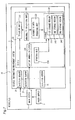
- Fig. 1 is a block diagram of an overall structure of the motorcycle 1.
- the motorcycle 1 includes a vehicle information management system 2, a power supply 3, and a main switch 4.
- the vehicle information management system 2 includes a plurality of detection sensors 21 and an ECU (electronic control unit) 23.
- the plurality of detection sensors 21 (corresponding to a parameter detector according to the present invention) are provided at an engine of the motorcycle 1, the power supply 3, and the like.
- the detection sensors 21 each detect a parameter related to a vehicle state.
- the plurality of detection sensors 21 include various sensors such as a vehicle speed sensor that detects a vehicle speed and a throttle sensor.
- the plurality of detection sensors 21 are connected to the ECU 23.
- the ECU 23 controls the engine and the like.
- the ECU 23 includes an obtaining unit 231, an abnormality specifying unit 232, a diagnostic data producing unit 233, an updating unit 234, an activation time detector 235, and a storage 24.
- the obtaining unit 231 obtains parameters about a vehicle state from the plurality of detection sensors 21.
- the abnormality specifying unit 232 specifies the type of an abnormality about the vehicle based on the parameters obtained by the obtaining unit 231.
- the abnormality specifying unit 232 determines whether the parameters detected by the detection sensors 21 are each within a predetermined normal range and specifies the type of the abnormality based on parameters outside the normal range.
- the abnormality specifying unit 232 specifies the type of the abnormality based on the abnormality specifying data stored in the storage 24.
- the abnormality specifying data is data that associates an abnormality type and a range of a parameter outside which an abnormality is determined for each parameter.
- a condition for determining recovery is different among types of abnormalities.
- a disconnection in a detection sensor 21 is caused for example and connection of a line is later detected, it is determined that the disconnection in the detector sensor 21 has been repaired.
- the association between the abnormalities and corresponding recovery conditions are stored in the storage 24.
- the diagnostic data producing unit 233 produces diagnostic data based on parameters detected by the plurality of detection sensors 21 when the abnormality specifying unit 232 specifies an abnormality.
- the diagnostic data producing unit 233 arranges the parameters in a predetermined order to produce the diagnostic data.
- the updating unit 234 updates abnormality data (freeze frame data) stored in the storage 24.
- the abnormality data includes diagnostic data, type information that indicates an abnormality type, occurrence number information that indicates the number of occurrences of the abnormality specified by the type information, and time information that indicates time during which the ECU 23 is activated.
- the updating unit 234 changes the occurrence number information to the latest information and overwrites the diagnostic data and the time information.
- changing to the latest information means changing the occurrence number information to the latest information based on the occurrence number information already stored in the storage 24.
- the overwriting means storing new data in the storage 24 in place of the data already stored in the storage 24.
- the updating unit 234 stores newly produced abnormality data in the empty region.
- the activation time detector 235 detects a period during which the ECU 23 is activated.
- the storage 24 pre-stores various kinds of data and information including abnormality specifying data used to specify an abnormality.
- the storage 24 includes first, second, and third storage regions 241, 242, and 243. Each of the storage regions stores only one piece of abnormality data.
- the power supply 3 supplies power to devices or the like provided in the vehicle.
- the power supply 3 supplies power to the ECU 23 and the plurality of detection sensors 21.
- the main switch 4 is provided between the power supply 3 and the plurality of detection sensors 21 and between the power supply 3 and the vehicle information management system 2.
- the main switch 4 responds to an operation of the ignition key by a rider to switch whether or not to supply power from the power supply 3 to the plurality of detection sensors 21 and the vehicle information management system 2.
- the detection sensors 21 start to detect parameters. At the time, the detected parameters are obtained at the obtaining unit 231.
- the ECU 23 carries out control to detect an abnormality.
- the type of an abnormality at the motorcycle 1 is specified based on the detected parameters. However, if there is an abnormality in the ignition device for the engine, for example, and the switch 4 is switched from on to off, the motorcycle 1 determines that the abnormality in the ignition device has been recovered. Therefore, if it is determined that there is an abnormality in the ignition device for the engine in the motorcycle 1, the ECU 23 determines recovery from the abnormality in response to switching of the main switch 4 from on to off even while it is actually not recovered from the abnormality.
- diagnostic data obtained when the abnormality in the ignition device occurred for the first time is more important in specifying and repairing the abnormality than diagnostic data based on the parameters detected as the main switch 4 is switched from off to on.
- the updating unit 234 when abnormality data related to an abnormality of the same type as that of an abnormality specified when the main switch 4 is switched from off to on is already stored in the storage 24, the updating unit 234 does not update the abnormality data. In this case, the updating unit 234 does not store the abnormality data in any of other storage regions. In this way, for the above-described abnormality in the ignition device for the engine, diagnostic data obtained when an abnormality occurred in the ignition device for the first time that is critical in specifying and repairing the abnormality can be maintained as it is stored in the storage 24.
- the updating unit 234 deletes the oldest abnormality data from all the storage regions to produce an empty region and stores the newly produced abnormality data in the empty region.
- the updating unit 234 determines the oldest data based on time information included in abnormality data stored in each of the storage regions.
- Fig. 2 shows an example of abnormality data stored in the storage region 24.
- One piece of abnormality data is stored in each of the storage regions in the storage 24.
- the items and numerical values of the abnormality data shown in Fig. 2 are examples only and they are not limited to these examples.
- the number of items of abnormality data may be different from the number in Fig. 2 .
- An abnormality type number included in the items of the abnormality data shown in Fig. 2 represents the type of an abnormality by a number.
- abnormality type numbers are previously set for the types of abnormalities
- abnormality data includes an abnormality type number corresponding to each of the abnormalities.
- the abnormality data includes information related to current carrying time that indicates activation time during which the ECU 23 is activated and information related to the number of how many times an abnormality designated by the abnormality type number occurred in addition to items related to the vehicle state.
- the diagnostic data is data related to items in the range represented by A.
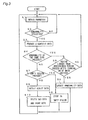
- Fig. 3 is a flowchart for illustrating an operation of the vehicle information management system 2. The operation of the vehicle information management system 2 will be described in conjunction with the flowchart.
- the plurality of detection sensors 21 obtain parameters related to a vehicle state.
- the obtaining unit 231 obtains parameters from the plurality of detection sensors 21 (step S1).
- the type of an abnormality about the vehicle is specified based on the parameters obtained by the detection sensors 21 (step S2). If there is no abnormality about the vehicle (NO in step S2), the detection sensors 21 each obtain a parameter for the vehicle again. On the other hand, if the type of the abnormality about the vehicle is specified (YES in step S2), diagnostic data is produced based on the parameters detected by the detection sensors 21 (step S3).
- step S4 It is determined whether abnormality data related to an abnormality of the same type as the abnormality specified by the abnormality specifying unit 232 is already stored in the storage regions in the storage 24 (step S4). If abnormality data for an abnormality of the same type as that of the abnormality specified by the abnormality specifying unit 232 is already stored in any of the storage regions (YES in step S4), it is determined if time longer than a prescribed period has passed after the main switch 4 was switched from off to on (step S5). If the time passed is not longer than the prescribed period (NO in step S5), parameters are once again obtained by the detection sensors 21. On the other hand, if a period longer than the prescribed period has passed (YES in step S5), occurrence number information in the abnormality data stored in the storage region is changed to the latest information by the updating unit 234 and diagnostic data is overwritten (step S6).
- step S7 If abnormality data for an abnormality of the same type as that of the abnormality specified by the abnormality specifying unit 232 is not stored in the storage regions of the storage 24 (NO in step S4), it is determined whether there is an empty region in the storage 24 (step S7). If there is an empty region (YES in step S7), the abnormality data is stored in the empty region (step S8). On the other hand, if there is no empty region in storage 24 (NO in step S7), the storage region having the oldest abnormality data stored therein among all the storage regions of the storage 24 is detected (step S9). The storage region having the oldest abnormality data stored therein is detected based on the time information of the abnormality data stored in each of the storage regions. The updating unit 234 deletes the oldest abnormality data to produce an empty region, and stores the newly produced abnormality data in the empty region (step S10).
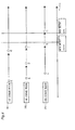
- Fig. 4 is a view showing an operation of the vehicle information management system 2 from the state in which no abnormality data is stored in the storage 24.
- the arrows following events A, B, C, D, E, F, G, and H indicate that an abnormality determined to have occurred in the vehicle continues.
- the part indicated by the broken line shows a state in which an abnormality determined to have occurred in the vehicle is determined to have repaired and abnormality data is stored in a storage region.
- abnormality data for A includes information that the abnormality type number is 13 and the number of occurrences of the abnormality is one. If the abnormality data is stored in the first storage region 241, then an abnormality designated by B occurs and diagnostic data is produced accordingly, it is determined whether abnormality data with the abnormality type number of B is stored in any of the storage regions.
- B represents an abnormality with the abnormality type number 15. Since abnormality data with the abnormality type number 15 is not stored in any of the storage regions, the abnormality data for B is stored in the second storage region 242.
- the abnormality data for B includes for example information that the abnormality type number is 15 and the number of occurrences of the abnormality is one. While the abnormality data is stored in the first and second storage regions 241 and 242, if an abnormality designated by C occurs and diagnostic data is produced, it is determined whether abnormality data with the abnormality type number of C is stored in any of the storage regions.
- C represents an abnormality with the abnormality type number 30. Since the abnormality data with the abnormality type number 30 is not stored in any of the storage regions, the abnormality data for C is stored in the third storage region 243.
- the abnormality data for C includes for example information that the abnormality type number is 30 and the number of occurrences of the abnormality is one.
- the abnormality with the abnormality type number 30 is a type of an abnormality whose recovery is hard to determine clearly similarly to when an abnormality occurs in an ignition device. In this case, it is automatically determined that the abnormality is recovered if the main switch 4 is switched from on to off.
- an abnormality specified by abnormality data stored in the second storage region 242 is recovered, the abnormality data stored in the second storage region 242 is maintained as it is stored therein.
- recovery of the abnormality in Fig. 4 is designated by D.
- an abnormality designated by E occurs and diagnostic data is produced, it is determined whether abnormality data with the abnormality type number of E is stored in any of the storage regions.
- E is for example an abnormality with the abnormality type number 21.
- abnormality data with the abnormality type number 21 is not stored in any of the storage regions and all the storage regions store abnormality data, it is determined which storage region stores the oldest abnormality data.
- the abnormality data for A i.e., the oldest data stored in the first storage region 241 is deleted to produce an empty region.
- the abnormality data is stored in the first storage region 241.
- the abnormality data for E includes information that the abnormality type number of the abnormality is 21 and the number of occurrences of the abnormality is one.
- an abnormality F (designated by the abnormality type number 15) of the same type as that of the abnormality of abnormality data stored in the second storage region 242 occurs, the occurrence number information included in the abnormality data stored in the second storage region 242 is changed to the latest information, and the diagnostic data is overwritten.
- the abnormality data for F includes information that the abnormality type number is 15 and the number of occurrences of the abnormality is two.
- Abnormality data related to an abnormality of the type automatically determined to have recovered in response to switching of the main switch 4 from on to off is stored in the third storage region 243. When the main switch 4 is switched from on to off, the abnormality designated by the abnormality type number 30 is determined to have recovered (G in Fig. 4 ).
- the detection sensors 21 detect parameters and the abnormality specifying unit 232 specifies an abnormality type.
- the abnormality with the abnormality type number 30 is not repaired in Fig. 4 , it is determined that the abnormality of the abnormality data stored in the third storage region 243 occurred.
- the detection of the occurrence of the abnormality of the abnormality data stored in the third storage region 243 is indicated by H.
- the third storage region 243 stores the abnormality data for C.
- Fig. 5 shows a state of how the motorcycle 1 is connected to the external device 5.
- the motorcycle 1 communicates with the external device 5.
- the external device 5 reads out abnormality data stored in the storage 24 from the motorcycle 1.
- the external device 5 displays the abnormality data read out from the motorcycle 1 at a display 51.
- the external device 5 displays the abnormality data read out from the motorcycle 1 at the display 51.
- a repair worker that repairs a malfunction checks the location of the abnormality or content of the malfunction from the abnormality data displayed at the display 51 and repairs it.
- the external device 5 may be a generally used PC instead of a dedicated reader.
- Fig. 6 is a partly enlarged front view of the meter 6 provided at the motorcycle 1.
- the meter 6 indicates parameters that show a state of the motorcycle 1 such as a vehicle speed.
- the meter 6 is provided with an abnormality warning unit 61 (corresponding to a warning unit according to the present invention) and an indicator 62.
- the abnormality warning unit 61 shows an abnormality type specified by the abnormality type specifying unit 232.
- the abnormality warning unit 61 lights up when the abnormality specifying unit 232 specifies an abnormality.
- a rider can become aware of the occurrence of an abnormality by the warning by the abnormality warning unit 61.
- the indicator 62 lets a rider become aware of a vehicle state such as the vehicle being low on fuel. A plurality of such indicators 62 are arranged side by side.
- abnormality data stored in a storage region includes occurrence number information.
- a repair worker can obtain information related to the occurrence frequency of the abnormality from the rider. Therefore, the repair worker can more easily determine which storage region stores abnormality data to be referred to based on the information from the rider and the abnormality data.
- the ECU 23 automatically determines that the abnormality is repaired when the main switch 4 is switched from on to off as to predetermined several types of abnormalities. Then, if, for example, the ECU 23 determines the occurrence of an abnormality again in response to the switching of the main switch 4 from off to on, and the data at the time is overwritten, abnormality data obtained when a malfunction was actually generated does not remain in the storage 24. Therefore, it would be hard for a repair worker who carries out maintenance or repair to specify an abnormality and a malfunction based on the abnormality data stored in the storage 24.
- abnormality data of an abnormality of the same type as that of the abnormality data is not yet stored in the storage 24 and there is an empty region in the storage 24, the abnormality data is stored in the empty region.
- abnormality data about an abnormality of the same type as the abnormality data is not yet stored in the storage 24 and there is no empty region in the storage 24
- abnormality data stored in the storage region stored with the oldest abnormality data is deleted to produce an empty region and the abnormality data is stored in the produced empty region. Therefore, new diagnostic data useful in determining an abnormality and a malfunction is more likely to remain in the storage regions. Therefore, it is easier to specify an abnormality and a malfunction when repair or maintenance is carried out.
- abnormality data includes time information.
- the time information is about time during which the ECU 23 is activated, and the oldest abnormality data or the like can be detected without additionally providing a new component such as a timer.
Landscapes
- Physics & Mathematics (AREA)
- General Physics & Mathematics (AREA)
- Engineering & Computer Science (AREA)
- Theoretical Computer Science (AREA)
- General Engineering & Computer Science (AREA)
- Software Systems (AREA)
- Mathematical Physics (AREA)
- Databases & Information Systems (AREA)
- Data Mining & Analysis (AREA)
- Mechanical Engineering (AREA)
- Computer Hardware Design (AREA)
- Combined Controls Of Internal Combustion Engines (AREA)
- Time Recorders, Dirve Recorders, Access Control (AREA)
- Testing And Monitoring For Control Systems (AREA)
Abstract
Description
- The present invention relates to vehicle information management systems and more specifically to a vehicle information management system that manages freeze frame data.
- There is a known vehicle adapted to store freeze frame data for a vehicle in a storage in order to use it to diagnose and repair a malfunction for the occasion of an abnormality generated in the vehicle. Here, the freeze frame data refers to data that includes parameters related to a vehicle state and is used for diagnosing a malfunction in a vehicle. When the vehicle is diagnosed or repaired, the freeze frame data is read out from the storage using an external device. A worker in charge of repair and maintenance specifies the cause of a malfunction or the like based on the read out freeze frame data.
- If freeze frame data obtained upon detecting an abnormality about a vehicle is entirely stored, a storage with a large storage capacity is necessary, and it takes time to search for data necessary for clarifying the cause of a malfunction at the time of diagnosing and repairing the vehicle. There is a known method of storing two kinds of freeze frame data, i.e., freeze frame data obtained when an abnormality occurs for the first time and freeze frame data obtained when an abnormality occurs for the last time in order to solve the problems (see Patent Document 1).
- Patent Document 1:
JP-A 2005-41273 - In a diagnostic data collecting device disclosed by the
above Patent Document 1, a storage includes first and second storage regions. Freeze frame data obtained upon detecting an abnormality for the first time is stored in the first storage region. Freeze frame data obtained upon detecting an abnormality for the last time is stored in the second storing region. - The diagnostic data collecting device disclosed by
Patent Document 1 needs two storage regions for one type of abnormalities. Therefore, a large storage capacity is necessary. In order to reduce the storage capacity, one of the two storage regions would be removed, and only one storage region would be provided. In the arrangement with only one storage region, it is not preferable to store freeze frame data obtained upon detecting an abnormality for the first time in view of repair or the like and only the latest freeze frame data is stored in the storage region. However, depending on the type of an abnormality, it may be difficult to specify the content of the abnormality only based on the latest freeze frame data. - It is an object of the present invention to provide a vehicle information management system without the necessity of a large capacity storage that allows an abnormality and a malfunction to be specified easily.
- A vehicle information management system manages diagnostic data that indicates a vehicle state and includes a plurality of parameter detectors, an abnormality specifying unit, a diagnostic data producing unit, a storage, and an updating unit. The parameter detectors each detect a parameter related to the vehicle state. The abnormality specifying unit specifies a type of an abnormality generated in the vehicle based on the parameters detected by the parameter detectors. The diagnostic data producing unit produces the diagnostic data based on the parameters detected by the parameter detectors when a type of an abnormality is specified by the abnormality specifying unit. The storage has a storage region capable of storing abnormality data including the diagnostic data, type information that indicates the type of the abnormality, and occurrence number information that indicates the number of occurrences of the abnormality specified by the type information. When a type of an abnormality is specified by the abnormality specifying unit and a new piece of the diagnostic data is produced and if abnormality data of the same type as the specified type is already stored in the storage region in the storage, the updating unit changes the occurrence number information to the latest information and overwrites and saves the diagnostic data in the storage region already stored with the abnormality data of the same type as the specified type.
- According to the above-described vehicle information management system, the latest diagnostic data useful in specifying an abnormality and a malfunction is stored in the storage region. Since the occurrence number information is changed to the latest information, consecutively occurring abnormalities can be specified. It can be determined that stored diagnostic data is not diagnostic data obtained when the abnormality occurred for the first time based on the occurrence number information. Therefore, as compared to the arrangement in which only the latest diagnostic data is stored, abnormalities and malfunctions can be specified more easily. Therefore, in the above-described vehicle information management system, a large capacity storage is not necessary and abnormalities and malfunctions are likely to be specified more easily.
-
-
Fig. 1 is a block diagram showing a structure of a motorcycle according to the present invention. -
Fig. 2 is a table showing a specific example of abnormality data stored in a storage region. -
Fig. 3 is a flowchart for illustrating an operation of a vehicle information management system. -
Fig. 4 is a view showing a specific example of an operation of the vehicle information management system. -
Fig. 5 shows an overall structure of a state of how the motorcycle is connected to an external device. -
Fig. 6 is a partly enlarged front view showing a periphery of a meter of the motorcycle. -
Fig. 7 is a block diagram of a motorcycle according to another embodiment. - Some vehicles include an arrangement adapted to store freeze frame data that indicates a vehicle state in a storage in order to specify the cause of a malfunction upon the occurrence of an abnormality in the vehicle. When an abnormality is detected in such a vehicle, the freeze frame data is obtained and stored in the storage. When the vehicle is repaired, a repair worker reads out the freeze frame data from the storage and specifies the type of the malfunction or the like.
- If the entire freeze frame data obtained upon detecting an abnormality about a vehicle is stored, a large storage capacity is necessary and much time is required to determine the cause of a malfunction in specifying or repairing the malfunction. In order to solve the problems, there has been an idea of an arrangement adapted to store two kinds of data, i.e., freeze frame data obtained upon detecting an abnormality for the first time and freeze frame data obtained upon detecting an abnormality for the last time.
- The inventor has come up with an idea of a vehicle information management system having a structure that does not need a large capacity storage and allows an abnormality and a malfunction to be easily specified. In the vehicle information management system according to the inventor's idea, abnormality data (freeze frame data) includes occurrence number information that indicates the number of occurrences of an abnormality. Therefore, the number of occurrences of abnormalities of the same type is available from the occurrence number information in the abnormality data. It can be determined that abnormality data stored in a storage is not abnormality data obtained upon detecting an abnormality for the first time when the abnormality is to be specified and a malfunction is diagnosed.
- In the above-described vehicle information management system, abnormality data stored in a storage region includes occurrence number information. If a rider finds out an abnormality and takes the vehicle including the above-described vehicle information diagnostic system to a shop for repairing, a repair worker can obtain information about the frequency of occurrences of the abnormality from the rider. Therefore, the repair worker can more easily determine which storage region stores abnormality data that should be referred to based on the information from the rider and the abnormality data.
- Now, a
motorcycle 1 as a kind of a saddle riding type vehicle according to one embodiment of the present invention will be described in conjunction with the accompanying drawings. In the drawings, the same or corresponding portions are designated by the same reference characters and description about each element will not be repeated. -
Fig. 1 is a block diagram of an overall structure of themotorcycle 1. Themotorcycle 1 includes a vehicleinformation management system 2, apower supply 3, and amain switch 4. - The vehicle
information management system 2 includes a plurality ofdetection sensors 21 and an ECU (electronic control unit) 23. The plurality of detection sensors 21 (corresponding to a parameter detector according to the present invention) are provided at an engine of themotorcycle 1, thepower supply 3, and the like. Thedetection sensors 21 each detect a parameter related to a vehicle state. For example, the plurality ofdetection sensors 21 include various sensors such as a vehicle speed sensor that detects a vehicle speed and a throttle sensor. The plurality ofdetection sensors 21 are connected to theECU 23. - The ECU 23 controls the engine and the like. The ECU 23 includes an obtaining
unit 231, anabnormality specifying unit 232, a diagnosticdata producing unit 233, anupdating unit 234, anactivation time detector 235, and astorage 24. - The obtaining
unit 231 obtains parameters about a vehicle state from the plurality ofdetection sensors 21. Theabnormality specifying unit 232 specifies the type of an abnormality about the vehicle based on the parameters obtained by the obtainingunit 231. Theabnormality specifying unit 232 determines whether the parameters detected by thedetection sensors 21 are each within a predetermined normal range and specifies the type of the abnormality based on parameters outside the normal range. Theabnormality specifying unit 232 specifies the type of the abnormality based on the abnormality specifying data stored in thestorage 24. The abnormality specifying data is data that associates an abnormality type and a range of a parameter outside which an abnormality is determined for each parameter. - In the
motorcycle 1, a condition for determining recovery is different among types of abnormalities. In themotorcycle 1, if a disconnection in adetection sensor 21 is caused for example and connection of a line is later detected, it is determined that the disconnection in thedetector sensor 21 has been repaired. If there is an abnormality about an ignition device for the engine for example, it is difficult to determine recovery from the abnormality correctly. Therefore, when themain switch 4 is turned off from its on state, it is determined that themotorcycle 1 has recovered from the abnormality in the ignition device. In this way, the conditions for determining recovery from abnormalities are different depending on the types of abnormalities. The association between the abnormalities and corresponding recovery conditions are stored in thestorage 24. - The diagnostic
data producing unit 233 produces diagnostic data based on parameters detected by the plurality ofdetection sensors 21 when theabnormality specifying unit 232 specifies an abnormality. The diagnosticdata producing unit 233 arranges the parameters in a predetermined order to produce the diagnostic data. - The updating
unit 234 updates abnormality data (freeze frame data) stored in thestorage 24. Here, the abnormality data includes diagnostic data, type information that indicates an abnormality type, occurrence number information that indicates the number of occurrences of the abnormality specified by the type information, and time information that indicates time during which theECU 23 is activated. When new diagnostic data is produced and abnormality data of the same type as the abnormality type specified by theabnormality specifying unit 232 is already stored in thestorage 24, the updatingunit 234 changes the occurrence number information to the latest information and overwrites the diagnostic data and the time information. Here, changing to the latest information means changing the occurrence number information to the latest information based on the occurrence number information already stored in thestorage 24. The overwriting means storing new data in thestorage 24 in place of the data already stored in thestorage 24. - When a new piece of diagnostic data is produced, and if abnormality data of the same type as that of the abnormality specified by the
abnormality specifying unit 232 is not stored in thestorage 24 and there is an empty storage region (herein after as "empty region") in thestorage 24, the updatingunit 234 stores newly produced abnormality data in the empty region. Theactivation time detector 235 detects a period during which theECU 23 is activated. - The
storage 24 pre-stores various kinds of data and information including abnormality specifying data used to specify an abnormality. Thestorage 24 includes first, second, andthird storage regions - The
power supply 3 supplies power to devices or the like provided in the vehicle. Thepower supply 3 supplies power to theECU 23 and the plurality ofdetection sensors 21. Themain switch 4 is provided between thepower supply 3 and the plurality ofdetection sensors 21 and between thepower supply 3 and the vehicleinformation management system 2. Themain switch 4 responds to an operation of the ignition key by a rider to switch whether or not to supply power from thepower supply 3 to the plurality ofdetection sensors 21 and the vehicleinformation management system 2. - When the
main switch 4 is switched from off to on, thedetection sensors 21 start to detect parameters. At the time, the detected parameters are obtained at the obtainingunit 231. TheECU 23 carries out control to detect an abnormality. The type of an abnormality at themotorcycle 1 is specified based on the detected parameters. However, if there is an abnormality in the ignition device for the engine, for example, and theswitch 4 is switched from on to off, themotorcycle 1 determines that the abnormality in the ignition device has been recovered. Therefore, if it is determined that there is an abnormality in the ignition device for the engine in themotorcycle 1, theECU 23 determines recovery from the abnormality in response to switching of themain switch 4 from on to off even while it is actually not recovered from the abnormality. Therefore, when themain switch 4 is switched from off to on, the abnormality in the ignition device is detected once again. However, in reality, the abnormality in the ignition device has not occurred again but it continues to exist from the first occurrence. Therefore, diagnostic data obtained when the abnormality in the ignition device occurred for the first time is more important in specifying and repairing the abnormality than diagnostic data based on the parameters detected as themain switch 4 is switched from off to on. - In the
motorcycle 1, when abnormality data related to an abnormality of the same type as that of an abnormality specified when themain switch 4 is switched from off to on is already stored in thestorage 24, the updatingunit 234 does not update the abnormality data. In this case, the updatingunit 234 does not store the abnormality data in any of other storage regions. In this way, for the above-described abnormality in the ignition device for the engine, diagnostic data obtained when an abnormality occurred in the ignition device for the first time that is critical in specifying and repairing the abnormality can be maintained as it is stored in thestorage 24. - If abnormality data related to an abnormality of the same type as the type of the abnormality specified upon producing new diagnostic data is not stored in the
storage 24 and there is no empty region in thestorage 24, the updatingunit 234 deletes the oldest abnormality data from all the storage regions to produce an empty region and stores the newly produced abnormality data in the empty region. Here, the updatingunit 234 determines the oldest data based on time information included in abnormality data stored in each of the storage regions. -
Fig. 2 shows an example of abnormality data stored in thestorage region 24. One piece of abnormality data is stored in each of the storage regions in thestorage 24. The items and numerical values of the abnormality data shown inFig. 2 are examples only and they are not limited to these examples. For example, the number of items of abnormality data may be different from the number inFig. 2 . - An abnormality type number included in the items of the abnormality data shown in
Fig. 2 represents the type of an abnormality by a number. In themotorcycle 1, abnormality type numbers are previously set for the types of abnormalities, and abnormality data includes an abnormality type number corresponding to each of the abnormalities. The abnormality data includes information related to current carrying time that indicates activation time during which theECU 23 is activated and information related to the number of how many times an abnormality designated by the abnormality type number occurred in addition to items related to the vehicle state. In the abnormality data shown inFig. 2 , the diagnostic data is data related to items in the range represented by A. -
Fig. 3 is a flowchart for illustrating an operation of the vehicleinformation management system 2. The operation of the vehicleinformation management system 2 will be described in conjunction with the flowchart. - The plurality of
detection sensors 21 obtain parameters related to a vehicle state. The obtainingunit 231 obtains parameters from the plurality of detection sensors 21 (step S1). When the parameters are obtained, the type of an abnormality about the vehicle is specified based on the parameters obtained by the detection sensors 21 (step S2). If there is no abnormality about the vehicle (NO in step S2), thedetection sensors 21 each obtain a parameter for the vehicle again. On the other hand, if the type of the abnormality about the vehicle is specified (YES in step S2), diagnostic data is produced based on the parameters detected by the detection sensors 21 (step S3). - It is determined whether abnormality data related to an abnormality of the same type as the abnormality specified by the
abnormality specifying unit 232 is already stored in the storage regions in the storage 24 (step S4). If abnormality data for an abnormality of the same type as that of the abnormality specified by theabnormality specifying unit 232 is already stored in any of the storage regions (YES in step S4), it is determined if time longer than a prescribed period has passed after themain switch 4 was switched from off to on (step S5). If the time passed is not longer than the prescribed period (NO in step S5), parameters are once again obtained by thedetection sensors 21. On the other hand, if a period longer than the prescribed period has passed (YES in step S5), occurrence number information in the abnormality data stored in the storage region is changed to the latest information by the updatingunit 234 and diagnostic data is overwritten (step S6). - If abnormality data for an abnormality of the same type as that of the abnormality specified by the
abnormality specifying unit 232 is not stored in the storage regions of the storage 24 (NO in step S4), it is determined whether there is an empty region in the storage 24 (step S7). If there is an empty region (YES in step S7), the abnormality data is stored in the empty region (step S8). On the other hand, if there is no empty region in storage 24 (NO in step S7), the storage region having the oldest abnormality data stored therein among all the storage regions of thestorage 24 is detected (step S9). The storage region having the oldest abnormality data stored therein is detected based on the time information of the abnormality data stored in each of the storage regions. The updatingunit 234 deletes the oldest abnormality data to produce an empty region, and stores the newly produced abnormality data in the empty region (step S10). -
Fig. 4 is a view showing an operation of the vehicleinformation management system 2 from the state in which no abnormality data is stored in thestorage 24. InFig. 4 , the arrows following events A, B, C, D, E, F, G, and H indicate that an abnormality determined to have occurred in the vehicle continues. InFig. 4 , the part indicated by the broken line shows a state in which an abnormality determined to have occurred in the vehicle is determined to have repaired and abnormality data is stored in a storage region. - If an abnormality designated by A for example occurs while no abnormality data is stored in any of the storage regions, abnormality data is stored in the
first region 241. Here, abnormality data for A includes information that the abnormality type number is 13 and the number of occurrences of the abnormality is one. If the abnormality data is stored in thefirst storage region 241, then an abnormality designated by B occurs and diagnostic data is produced accordingly, it is determined whether abnormality data with the abnormality type number of B is stored in any of the storage regions. Here, B represents an abnormality with theabnormality type number 15. Since abnormality data with theabnormality type number 15 is not stored in any of the storage regions, the abnormality data for B is stored in thesecond storage region 242. The abnormality data for B includes for example information that the abnormality type number is 15 and the number of occurrences of the abnormality is one. While the abnormality data is stored in the first andsecond storage regions abnormality type number 30. Since the abnormality data with theabnormality type number 30 is not stored in any of the storage regions, the abnormality data for C is stored in thethird storage region 243. The abnormality data for C includes for example information that the abnormality type number is 30 and the number of occurrences of the abnormality is one. The abnormality with theabnormality type number 30 is a type of an abnormality whose recovery is hard to determine clearly similarly to when an abnormality occurs in an ignition device. In this case, it is automatically determined that the abnormality is recovered if themain switch 4 is switched from on to off. - Then, if an abnormality specified by abnormality data stored in the
second storage region 242 is recovered, the abnormality data stored in thesecond storage region 242 is maintained as it is stored therein. Here, recovery of the abnormality inFig. 4 is designated by D. Then, if an abnormality designated by E occurs and diagnostic data is produced, it is determined whether abnormality data with the abnormality type number of E is stored in any of the storage regions. Here, E is for example an abnormality with theabnormality type number 21. However, since abnormality data with theabnormality type number 21 is not stored in any of the storage regions and all the storage regions store abnormality data, it is determined which storage region stores the oldest abnormality data. Then, the abnormality data for A, i.e., the oldest data stored in thefirst storage region 241 is deleted to produce an empty region. The abnormality data is stored in thefirst storage region 241. Here, the abnormality data for E includes information that the abnormality type number of the abnormality is 21 and the number of occurrences of the abnormality is one. - Then, if an abnormality F (designated by the abnormality type number 15) of the same type as that of the abnormality of abnormality data stored in the
second storage region 242 occurs, the occurrence number information included in the abnormality data stored in thesecond storage region 242 is changed to the latest information, and the diagnostic data is overwritten. Here, the abnormality data for F includes information that the abnormality type number is 15 and the number of occurrences of the abnormality is two. Abnormality data related to an abnormality of the type automatically determined to have recovered in response to switching of themain switch 4 from on to off is stored in thethird storage region 243. When themain switch 4 is switched from on to off, the abnormality designated by theabnormality type number 30 is determined to have recovered (G inFig. 4 ). Thedetection sensors 21 detect parameters and theabnormality specifying unit 232 specifies an abnormality type. In reality, since the abnormality with theabnormality type number 30 is not repaired inFig. 4 , it is determined that the abnormality of the abnormality data stored in thethird storage region 243 occurred. InFig. 4 , the detection of the occurrence of the abnormality of the abnormality data stored in thethird storage region 243 is indicated by H. However, since time longer than the prescribed time has not passed after themain switch 4 was switched from off to on, the abnormality data stored in thethird storage region 243 is not updated. Therefore, thethird storage region 243 stores the abnormality data for C. -
Fig. 5 shows a state of how themotorcycle 1 is connected to theexternal device 5. When a malfunction or an abnormality is specified and repaired, themotorcycle 1 communicates with theexternal device 5. Theexternal device 5 reads out abnormality data stored in thestorage 24 from themotorcycle 1. Theexternal device 5 displays the abnormality data read out from themotorcycle 1 at adisplay 51. Theexternal device 5 displays the abnormality data read out from themotorcycle 1 at thedisplay 51. A repair worker that repairs a malfunction checks the location of the abnormality or content of the malfunction from the abnormality data displayed at thedisplay 51 and repairs it. Theexternal device 5 may be a generally used PC instead of a dedicated reader. -
Fig. 6 is a partly enlarged front view of themeter 6 provided at themotorcycle 1. Themeter 6 indicates parameters that show a state of themotorcycle 1 such as a vehicle speed. Themeter 6 is provided with an abnormality warning unit 61 (corresponding to a warning unit according to the present invention) and anindicator 62. Theabnormality warning unit 61 shows an abnormality type specified by the abnormalitytype specifying unit 232. Theabnormality warning unit 61 lights up when theabnormality specifying unit 232 specifies an abnormality. A rider can become aware of the occurrence of an abnormality by the warning by theabnormality warning unit 61. Theindicator 62 lets a rider become aware of a vehicle state such as the vehicle being low on fuel. A plurality ofsuch indicators 62 are arranged side by side. - In the above described
motorcycle 1, when a type of a new abnormality is specified and diagnostic data therefor is produced and if abnormality data for an abnormality of the same type as that of the abnormality specified by theabnormality specifying unit 232 is already stored in any of the storage regions, the diagnostic data in the storage region is overwritten and the occurrence number information is changed to the latest information. Therefore, in repairing, a repair worker can determine whether the abnormality data stored in the storage region is data obtained upon detecting the abnormality for the first time by checking the occurrence number information. The repair worker can also know the number of how many times the abnormality of the same type has occurred based on the occurrence number information. Since the storage regions store the latest diagnostic data, the repair worker can carry out repair based on the latest diagnostic data. - In the above-described
motorcycle 1, abnormality data stored in a storage region includes occurrence number information. When a rider finds out the occurrence of an abnormality and takes themotorcycle 1 to a shop for repairing, a repair worker can obtain information related to the occurrence frequency of the abnormality from the rider. Therefore, the repair worker can more easily determine which storage region stores abnormality data to be referred to based on the information from the rider and the abnormality data. - In the
motorcycle 1, theECU 23 automatically determines that the abnormality is repaired when themain switch 4 is switched from on to off as to predetermined several types of abnormalities. Then, if, for example, theECU 23 determines the occurrence of an abnormality again in response to the switching of themain switch 4 from off to on, and the data at the time is overwritten, abnormality data obtained when a malfunction was actually generated does not remain in thestorage 24. Therefore, it would be hard for a repair worker who carries out maintenance or repair to specify an abnormality and a malfunction based on the abnormality data stored in thestorage 24. - In the above-described
motorcycle 1, however, if an abnormality of the same type as that of abnormality data already stored in a storage region occurs before a period longer than a prescribed period passes after themain switch 4 is switched from off to on, the diagnostic data stored in the storage region is not updated. Therefore, the repair worker can confirm abnormality data obtained at the actual occurrence of the abnormality, so that the abnormality or malfunction can be specified more easily at the time of repairing. - In the above-described
motorcycle 1, if abnormality data of an abnormality of the same type as that of the abnormality data is not yet stored in thestorage 24 and there is an empty region in thestorage 24, the abnormality data is stored in the empty region. In the above-describedmotorcycle 1, if abnormality data about an abnormality of the same type as the abnormality data is not yet stored in thestorage 24 and there is no empty region in thestorage 24, abnormality data stored in the storage region stored with the oldest abnormality data is deleted to produce an empty region and the abnormality data is stored in the produced empty region. Therefore, new diagnostic data useful in determining an abnormality and a malfunction is more likely to remain in the storage regions. Therefore, it is easier to specify an abnormality and a malfunction when repair or maintenance is carried out. - In the above-described
motorcycle 1, abnormality data includes time information. The time information is about time during which theECU 23 is activated, and the oldest abnormality data or the like can be detected without additionally providing a new component such as a timer. -
- (1) The above-described embodiment relates to the
motorcycle 1 but the invention is not limited to the arrangement and also applicable to a three- or four- wheeled saddle riding type vehicle. -
- (2) In the
motorcycle 1 according to the above described embodiment, the oldest abnormality data is detected based on time information included in abnormality data when the storage region stored with the oldest abnormality data is detected. The time information is detected by theactivation time detector 235. The invention is not limited to the arrangement and the motorcycle may include an arrangement shown inFig. 7 . Amotorcycle 10 shown inFig. 7 includes anactivation number detector 236 instead of theactivation time detector 235. Theactivation number detector 236 detects the number of how many times themain switch 4 is switched from off to on and produces number information. The abnormality data includes diagnostic data, type information that indicates the type of an abnormality, the occurrence number of the abnormality specified by the type information, and number information that indicates the activation number of theECU 23. In themotorcycle 10, the storage region stored with the oldest abnormality data is detected based on the number information. In this way, the oldest data or the like can be detected without additionally providing a new component such as a timer. -
- (3) In the above-described embodiment, the
abnormality warning unit 61 is provided at themeter 6 but the invention is not limited to this arrangement. It can be provided in any location as long as a rider can recognize it and may be provided for example around the handle. Theabnormality warning unit 61 does not have to indicate a content of warning but a lamp (corresponding to a warning unit according to the present invention) may be turn on to make such warning. For example, the indicator 62 (corresponding to a warning unit according to the present invention) may be lighted up to make warning about an abnormality according to the invention. -
- (4) In the above-described embodiment, it is determined whether a time period longer than a prescribed time period passes after the
main switch 4 is switched from off to on, and the control branches between updating and not updating a storage region. However, the invention is not limited to this arrangement, and an arrangement without any consideration of switching of themain switch 4 may be employed. However, in this case, abnormality data is updated every time themain switch 4 is switched, so that it is more difficult for example to specify an abnormality than the above-described embodiment. -
- (5) In the above-described embodiment, the
motorcycle 1 includes the storage having the three storage regions but the invention is not limited to the arrangement. The number of the storage regions may be one or two or four or more. -
- (6) In the above-described embodiment, abnormality data includes time information. However, the invention is not limited to this and the time information does not have to be included in the abnormality data.
-
- (7) In the above description of the embodiment, an abnormality in an ignition device is illustrated as an example of an abnormality determined to have repaired when the
main switch 4 is switched from on to off, but the invention is not limited to this. According to the invention, it may be set so that all the abnormalities may be determined to have repaired when themain switch 4 is switched from on to off, and any other abnormalities (recovery from which may hardly be determined correctly) may be set as such an abnormality.
Claims (11)
- A vehicle information management system (2) that manages diagnostic data that indicates a vehicle state, comprising:a plurality of parameter detectors (21) each configured to detect a parameter related to the vehicle state;an abnormality specifying unit (232) configured to specify a type of an abnormality generated in the vehicle based on the parameters detected by the parameter detectors (21);a diagnostic data producing unit (233) configured to produce the diagnostic data based on the parameters detected by the parameter detectors (21) when a type of an abnormality is specified by the abnormality specifying unit (232);a storage (24) having a storage region (241, 242, 243) configured to store abnormality data including the diagnostic data, type information that indicates the type of the abnormality, and occurrence number information that indicates the number of occurrences of the abnormality specified by the type information; andan updating unit (234) that is configured to change the occurrence number information to latest information and to overwrite and save a new piece of diagnostic data in the storage region (241, 242, 243) in the storage (24) when a type of an abnormality is specified by the abnormality specifying unit (232) and the new piece of the diagnostic data is produced and if abnormality data of the same type as the specified type is already stored in the storage region (241, 242, 243).
- The vehicle information management system (2) according to claim 1, wherein when a main switch (4) of the vehicle is turned on, the parameter detectors (21) each start to detect a parameter about the vehicle,
the diagnostic data producing unit (233) is configured to produce the diagnostic data based on the parameters detected in a prescribed period after the main switch (4) is turned on, and
when a type of an abnormality is specified by the abnormality specifying unit (232) based on the diagnostic data produced in the prescribed period after the main switch (4) is turned on and the abnormality data of the same type as the specified type is already stored in the storage region (241, 242, 243), the updating unit (234) is configured to neither overwrite the diagnostic data in the storage region (241, 242, 243) already stored with the abnormality data of the same type as the specified type nor change the occurrence number information to latest information. - The vehicle information management system (2) according to claim 1 or 2, wherein the storage (24) comprises a plurality of storage regions (241, 242, 243).
- The vehicle information management system (2) according to claim 3, wherein when a type of an abnormality is specified by the abnormality specifying unit (232) and a new piece of the diagnostic data is produced, and
when the abnormality data of the same type as the specified type is not stored in any of the plurality of regions (241, 242, 243) and there is an empty region among the plurality of regions (241, 242, 243), the updating unit (234) is configured to store a newly produced piece of the abnormality data in the empty region. - The vehicle information management system (2) according to claim 3 or 4, wherein when a type of an abnormality is specified by the abnormality specifying unit (232) and a new piece of the diagnostic data is produced, and when the abnormality data of the same type as the specified type is not stored in any of the plurality of regions (241, 242, 243) and there is no empty region among the plurality of regions (241, 242, 243), the updating unit (234) is configured to delete the oldest piece of the abnormality data to produce an empty region and to then store a newly produced piece of the abnormality data in the empty region.
- The vehicle information management system (2) according to any one of claims 1 to 5, further comprising an activation time detector (235) that is configured to detect a period during which an electronic control unit (23) of the vehicle that is supplied with power in response to an operation of the main switch (4) is activated,
the abnormality data further including time information related to activation time detected by the activation time detector (235). - The vehicle information management system (2) according to any one of claims 1 to 5, further comprising an activation number detector (236) that is configured to count a number of how many times the electronic control unit (23) of the vehicle that is supplied with power in response to an operation of the main switch (4) is activated,
the abnormality data further including number information related to an activation number detected by the activation number detector (236). - A malfunction diagnostic system, comprising:a vehicle information management system (2) according to any one of claims 1 to 7;a reader (5) configured to read the abnormality data stored in the storage (24) from the vehicle information management system (2); anda display (51) configured to display the data read from the vehicle information management system (2).
- A saddle riding type vehicle (1) comprising a vehicle information management system (2) according to any one of claims 1 to 7.
- The saddle riding type vehicle (1) according to claim 9, further comprising a warning unit (61) configured to warn a rider about an abnormality,
the warning unit is configured to light up when a type of an abnormality is specified by the abnormality specifying unit (232). - A vehicle information management method for managing diagnostic data that indicates a vehicle state, comprising:a first step of detecting a parameter related to the vehicle state;a second step of producing the diagnostic data based on the detected parameter;a third step of specifying a type of an abnormality generated in the vehicle based on the diagnostic data; anda fourth step of changing the occurrence number information to latest information and then overwriting and saving a new piece of the diagnostic data in a storage region when the new piece of the diagnostic data is produced and the abnormality data of the same type as the specified type is already stored in the storage region.
Applications Claiming Priority (1)
| Application Number | Priority Date | Filing Date | Title |
|---|---|---|---|
| JP2012156403A JP5350521B1 (en) | 2012-07-12 | 2012-07-12 | Vehicle information management system. |
Publications (3)
| Publication Number | Publication Date |
|---|---|
| EP2685432A2 true EP2685432A2 (en) | 2014-01-15 |
| EP2685432A3 EP2685432A3 (en) | 2018-01-17 |
| EP2685432B1 EP2685432B1 (en) | 2019-05-22 |
Family
ID=47630074
Family Applications (1)
| Application Number | Title | Priority Date | Filing Date |
|---|---|---|---|
| EP12192793.3A Active EP2685432B1 (en) | 2012-07-12 | 2012-11-15 | Vehicle information management system |
Country Status (6)
| Country | Link |
|---|---|
| US (1) | US8831834B2 (en) |
| EP (1) | EP2685432B1 (en) |
| JP (1) | JP5350521B1 (en) |
| CN (1) | CN103538537B (en) |
| BR (1) | BR102012031368B1 (en) |
| ES (1) | ES2728907T3 (en) |
Families Citing this family (8)
| Publication number | Priority date | Publication date | Assignee | Title |
|---|---|---|---|---|
| JP6119682B2 (en) | 2014-06-27 | 2017-04-26 | 株式会社デンソー | Electronic control unit |
| WO2018105547A1 (en) * | 2016-12-06 | 2018-06-14 | ヤマハ発動機株式会社 | Abnormality detection device |
| CN106527410B (en) * | 2016-12-29 | 2019-04-16 | 浙江吉利汽车研究院有限公司 | A data recording gateway for vehicles and a diagnostic system based on the gateway |
| CN109215170B (en) * | 2017-07-04 | 2021-03-02 | 百度在线网络技术(北京)有限公司 | Driving data storage method, device and equipment |
| US10083588B1 (en) * | 2017-07-05 | 2018-09-25 | Continental Automotive Systems, Inc. | Vehicle safety notification system |
| JP6705547B1 (en) * | 2019-10-18 | 2020-06-03 | トヨタ自動車株式会社 | Vehicle control device, vehicle control system, and vehicle learning device |
| JP7447855B2 (en) * | 2021-03-23 | 2024-03-12 | トヨタ自動車株式会社 | Abnormality diagnosis device |
| CN114756299A (en) * | 2022-04-21 | 2022-07-15 | 国汽智控(北京)科技有限公司 | Vehicle failure processing method and device, electronic device and storage medium |
Family Cites Families (20)
| Publication number | Priority date | Publication date | Assignee | Title |
|---|---|---|---|---|
| JPS5963344A (en) * | 1982-10-01 | 1984-04-11 | Fuji Heavy Ind Ltd | Self-diagnosis system for internal-combustion engine |
| JPS62291537A (en) | 1986-06-11 | 1987-12-18 | Nippon Denso Co Ltd | Synthetic diagnostic apparatus for vehicle |
| JPH0827221B2 (en) | 1987-09-22 | 1996-03-21 | 富士重工業株式会社 | Vehicle diagnostic device |
| JP3372102B2 (en) * | 1994-04-27 | 2003-01-27 | 富士重工業株式会社 | Fault diagnosis device |
| JPH0893544A (en) * | 1994-09-21 | 1996-04-09 | Nippondenso Co Ltd | Diagnostic data storing system |
| JP3379260B2 (en) | 1995-01-23 | 2003-02-24 | 株式会社デンソー | Diagnosis device for vehicles |
| JPH08270494A (en) | 1995-03-31 | 1996-10-15 | Hitachi Ltd | Data monitor diagnosis method when the engine is stopped |
| JP3797395B2 (en) | 1997-02-27 | 2006-07-19 | ヤマハマリン株式会社 | Ship propulsion machine |
| AU6157599A (en) * | 1998-09-21 | 2000-04-10 | Master Tech Engineering, Inc. | Event recorder |
| US6931309B2 (en) * | 2003-05-06 | 2005-08-16 | Innosurance, Inc. | Motor vehicle operating data collection and analysis |
| JP2005041273A (en) | 2003-07-23 | 2005-02-17 | Toyota Motor Corp | Diagnostic data collection apparatus and method |
| JP4882528B2 (en) * | 2005-06-10 | 2012-02-22 | 日本精工株式会社 | Control device for electric power steering device |
| EP1731405B1 (en) | 2005-06-10 | 2009-06-03 | Nsk Ltd., | Controller of electric power steering apparatus |
| JP4736828B2 (en) * | 2006-02-03 | 2011-07-27 | 株式会社デンソー | Electronic control unit |
| JP2008117129A (en) | 2006-11-02 | 2008-05-22 | Nsk Ltd | Abnormality analysis data collection device and in-vehicle control device using the same |
| JP4573884B2 (en) * | 2008-06-18 | 2010-11-04 | 三菱電機株式会社 | In-vehicle electronic control unit power failure detection circuit |
| JP5313099B2 (en) | 2009-09-25 | 2013-10-09 | 日立建機株式会社 | Machine abnormality monitoring device |
| JP5387495B2 (en) | 2010-04-27 | 2014-01-15 | 株式会社デンソー | Electronic control device for vehicle |
| US8725312B2 (en) * | 2011-08-12 | 2014-05-13 | Kawasaki Jukogyo Kabushiki Kaisha | System for obtaining information in vehicle |
| JP5273753B1 (en) * | 2012-07-12 | 2013-08-28 | ヤマハ発動機株式会社 | Vehicle information management system. |
-
2012
- 2012-07-12 JP JP2012156403A patent/JP5350521B1/en not_active Expired - Fee Related
- 2012-11-15 ES ES12192793T patent/ES2728907T3/en active Active
- 2012-11-15 EP EP12192793.3A patent/EP2685432B1/en active Active
- 2012-11-20 US US13/681,512 patent/US8831834B2/en active Active
- 2012-11-30 BR BR102012031368-5A patent/BR102012031368B1/en active IP Right Grant
- 2012-11-30 CN CN201210506978.6A patent/CN103538537B/en active Active
Non-Patent Citations (1)
| Title |
|---|
| None |
Also Published As
| Publication number | Publication date |
|---|---|
| JP5350521B1 (en) | 2013-11-27 |
| CN103538537A (en) | 2014-01-29 |
| US8831834B2 (en) | 2014-09-09 |
| BR102012031368B1 (en) | 2020-11-17 |
| US20140015661A1 (en) | 2014-01-16 |
| BR102012031368A2 (en) | 2015-10-20 |
| EP2685432B1 (en) | 2019-05-22 |
| JP2014019183A (en) | 2014-02-03 |
| EP2685432A3 (en) | 2018-01-17 |
| ES2728907T3 (en) | 2019-10-29 |
| CN103538537B (en) | 2015-12-09 |
Similar Documents
| Publication | Publication Date | Title |
|---|---|---|
| EP2685432B1 (en) | Vehicle information management system | |
| EP2685429B1 (en) | Vehicle information management system | |
| US6172602B1 (en) | Maintenance alert system for heavy-duty trucks | |
| US6587767B2 (en) | Maintenance alert system for heavy-duty trucks | |
| EP1569174B1 (en) | Data recording apparatus and data recording method | |
| JP2017194398A (en) | Maintenance notification device | |
| CN107179764A (en) | Vehicle device equipment with vehicle diagnostics function | |
| CN103339330B (en) | Working rig | |
| EP1589490B1 (en) | Control unit and data transmitting method | |
| JP4417124B2 (en) | Mileage display device | |
| JP6241646B2 (en) | In-vehicle battery information display device | |
| JP2013024445A (en) | Refrigerator | |
| JP5650007B2 (en) | Working machine | |
| US20130211664A1 (en) | Tire monitoring system for a vehicle | |
| US20180018834A1 (en) | Methods and systems of using vehicle system data to improve the operation of off-road vehicles | |
| KR20130110714A (en) | Apparatus and method for senseing removal of on board diagonosis | |
| EP2685431A2 (en) | Vehicle information management system | |
| EP1569175A2 (en) | Data recording apparatus and data recording method | |
| JPS61129357A (en) | Vehicle control device having diagnostic function | |
| CN120735598A (en) | Method and related equipment for determining residual hydrogen quantity of vehicle | |
| JP2005022528A (en) | Vehicle information display device | |
| JP2005188983A (en) | Vehicle self-diagnosis result notification system and method | |
| KR20040027714A (en) | The device of diagnosis using vehicle | |
| CN1350496A (en) | Indication method and indicator device for indicating status information |
Legal Events
| Date | Code | Title | Description |
|---|---|---|---|
| PUAI | Public reference made under article 153(3) epc to a published international application that has entered the european phase |
Free format text: ORIGINAL CODE: 0009012 |
|
| AK | Designated contracting states |
Kind code of ref document: A2 Designated state(s): AL AT BE BG CH CY CZ DE DK EE ES FI FR GB GR HR HU IE IS IT LI LT LU LV MC MK MT NL NO PL PT RO RS SE SI SK SM TR |
|
| AX | Request for extension of the european patent |
Extension state: BA ME |
|
| PUAL | Search report despatched |
Free format text: ORIGINAL CODE: 0009013 |
|
| AK | Designated contracting states |
Kind code of ref document: A3 Designated state(s): AL AT BE BG CH CY CZ DE DK EE ES FI FR GB GR HR HU IE IS IT LI LT LU LV MC MK MT NL NO PL PT RO RS SE SI SK SM TR |
|
| AX | Request for extension of the european patent |
Extension state: BA ME |
|
| RIC1 | Information provided on ipc code assigned before grant |
Ipc: G07C 5/08 20060101AFI20171213BHEP Ipc: G01M 17/007 20060101ALI20171213BHEP |
|
| STAA | Information on the status of an ep patent application or granted ep patent |
Free format text: STATUS: REQUEST FOR EXAMINATION WAS MADE |
|
| 17P | Request for examination filed |
Effective date: 20180226 |
|
| RBV | Designated contracting states (corrected) |
Designated state(s): AL AT BE BG CH CY CZ DE DK EE ES FI FR GB GR HR HU IE IS IT LI LT LU LV MC MK MT NL NO PL PT RO RS SE SI SK SM TR |
|
| STAA | Information on the status of an ep patent application or granted ep patent |
Free format text: STATUS: EXAMINATION IS IN PROGRESS |
|
| 17Q | First examination report despatched |
Effective date: 20180703 |
|
| GRAP | Despatch of communication of intention to grant a patent |
Free format text: ORIGINAL CODE: EPIDOSNIGR1 |
|
| STAA | Information on the status of an ep patent application or granted ep patent |
Free format text: STATUS: GRANT OF PATENT IS INTENDED |
|
| INTG | Intention to grant announced |
Effective date: 20190110 |
|
| GRAS | Grant fee paid |
Free format text: ORIGINAL CODE: EPIDOSNIGR3 |
|
| GRAA | (expected) grant |
Free format text: ORIGINAL CODE: 0009210 |
|
| STAA | Information on the status of an ep patent application or granted ep patent |
Free format text: STATUS: THE PATENT HAS BEEN GRANTED |
|
| AK | Designated contracting states |
Kind code of ref document: B1 Designated state(s): AL AT BE BG CH CY CZ DE DK EE ES FI FR GB GR HR HU IE IS IT LI LT LU LV MC MK MT NL NO PL PT RO RS SE SI SK SM TR |
|
| REG | Reference to a national code |
Ref country code: GB Ref legal event code: FG4D |
|
| REG | Reference to a national code |
Ref country code: CH Ref legal event code: EP |
|
| REG | Reference to a national code |
Ref country code: IE Ref legal event code: FG4D |
|
| REG | Reference to a national code |
Ref country code: DE Ref legal event code: R096 Ref document number: 602012060320 Country of ref document: DE |
|
| REG | Reference to a national code |
Ref country code: AT Ref legal event code: REF Ref document number: 1137011 Country of ref document: AT Kind code of ref document: T Effective date: 20190615 |
|
| REG | Reference to a national code |
Ref country code: NL Ref legal event code: MP Effective date: 20190522 |
|
| REG | Reference to a national code |
Ref country code: LT Ref legal event code: MG4D |
|
| REG | Reference to a national code |
Ref country code: ES Ref legal event code: FG2A Ref document number: 2728907 Country of ref document: ES Kind code of ref document: T3 Effective date: 20191029 |
|
| PG25 | Lapsed in a contracting state [announced via postgrant information from national office to epo] |
Ref country code: PT Free format text: LAPSE BECAUSE OF FAILURE TO SUBMIT A TRANSLATION OF THE DESCRIPTION OR TO PAY THE FEE WITHIN THE PRESCRIBED TIME-LIMIT Effective date: 20190922 Ref country code: AL Free format text: LAPSE BECAUSE OF FAILURE TO SUBMIT A TRANSLATION OF THE DESCRIPTION OR TO PAY THE FEE WITHIN THE PRESCRIBED TIME-LIMIT Effective date: 20190522 Ref country code: LT Free format text: LAPSE BECAUSE OF FAILURE TO SUBMIT A TRANSLATION OF THE DESCRIPTION OR TO PAY THE FEE WITHIN THE PRESCRIBED TIME-LIMIT Effective date: 20190522 Ref country code: NO Free format text: LAPSE BECAUSE OF FAILURE TO SUBMIT A TRANSLATION OF THE DESCRIPTION OR TO PAY THE FEE WITHIN THE PRESCRIBED TIME-LIMIT Effective date: 20190822 Ref country code: FI Free format text: LAPSE BECAUSE OF FAILURE TO SUBMIT A TRANSLATION OF THE DESCRIPTION OR TO PAY THE FEE WITHIN THE PRESCRIBED TIME-LIMIT Effective date: 20190522 Ref country code: NL Free format text: LAPSE BECAUSE OF FAILURE TO SUBMIT A TRANSLATION OF THE DESCRIPTION OR TO PAY THE FEE WITHIN THE PRESCRIBED TIME-LIMIT Effective date: 20190522 Ref country code: SE Free format text: LAPSE BECAUSE OF FAILURE TO SUBMIT A TRANSLATION OF THE DESCRIPTION OR TO PAY THE FEE WITHIN THE PRESCRIBED TIME-LIMIT Effective date: 20190522 Ref country code: HR Free format text: LAPSE BECAUSE OF FAILURE TO SUBMIT A TRANSLATION OF THE DESCRIPTION OR TO PAY THE FEE WITHIN THE PRESCRIBED TIME-LIMIT Effective date: 20190522 |
|
| PG25 | Lapsed in a contracting state [announced via postgrant information from national office to epo] |
Ref country code: RS Free format text: LAPSE BECAUSE OF FAILURE TO SUBMIT A TRANSLATION OF THE DESCRIPTION OR TO PAY THE FEE WITHIN THE PRESCRIBED TIME-LIMIT Effective date: 20190522 Ref country code: LV Free format text: LAPSE BECAUSE OF FAILURE TO SUBMIT A TRANSLATION OF THE DESCRIPTION OR TO PAY THE FEE WITHIN THE PRESCRIBED TIME-LIMIT Effective date: 20190522 Ref country code: BG Free format text: LAPSE BECAUSE OF FAILURE TO SUBMIT A TRANSLATION OF THE DESCRIPTION OR TO PAY THE FEE WITHIN THE PRESCRIBED TIME-LIMIT Effective date: 20190822 Ref country code: GR Free format text: LAPSE BECAUSE OF FAILURE TO SUBMIT A TRANSLATION OF THE DESCRIPTION OR TO PAY THE FEE WITHIN THE PRESCRIBED TIME-LIMIT Effective date: 20190823 |
|
| REG | Reference to a national code |
Ref country code: AT Ref legal event code: MK05 Ref document number: 1137011 Country of ref document: AT Kind code of ref document: T Effective date: 20190522 |
|
| PG25 | Lapsed in a contracting state [announced via postgrant information from national office to epo] |
Ref country code: CZ Free format text: LAPSE BECAUSE OF FAILURE TO SUBMIT A TRANSLATION OF THE DESCRIPTION OR TO PAY THE FEE WITHIN THE PRESCRIBED TIME-LIMIT Effective date: 20190522 Ref country code: AT Free format text: LAPSE BECAUSE OF FAILURE TO SUBMIT A TRANSLATION OF THE DESCRIPTION OR TO PAY THE FEE WITHIN THE PRESCRIBED TIME-LIMIT Effective date: 20190522 Ref country code: RO Free format text: LAPSE BECAUSE OF FAILURE TO SUBMIT A TRANSLATION OF THE DESCRIPTION OR TO PAY THE FEE WITHIN THE PRESCRIBED TIME-LIMIT Effective date: 20190522 Ref country code: EE Free format text: LAPSE BECAUSE OF FAILURE TO SUBMIT A TRANSLATION OF THE DESCRIPTION OR TO PAY THE FEE WITHIN THE PRESCRIBED TIME-LIMIT Effective date: 20190522 Ref country code: DK Free format text: LAPSE BECAUSE OF FAILURE TO SUBMIT A TRANSLATION OF THE DESCRIPTION OR TO PAY THE FEE WITHIN THE PRESCRIBED TIME-LIMIT Effective date: 20190522 Ref country code: SK Free format text: LAPSE BECAUSE OF FAILURE TO SUBMIT A TRANSLATION OF THE DESCRIPTION OR TO PAY THE FEE WITHIN THE PRESCRIBED TIME-LIMIT Effective date: 20190522 |
|
| REG | Reference to a national code |
Ref country code: DE Ref legal event code: R097 Ref document number: 602012060320 Country of ref document: DE |
|
| PG25 | Lapsed in a contracting state [announced via postgrant information from national office to epo] |
Ref country code: SM Free format text: LAPSE BECAUSE OF FAILURE TO SUBMIT A TRANSLATION OF THE DESCRIPTION OR TO PAY THE FEE WITHIN THE PRESCRIBED TIME-LIMIT Effective date: 20190522 |
|
| PLBE | No opposition filed within time limit |
Free format text: ORIGINAL CODE: 0009261 |
|
| STAA | Information on the status of an ep patent application or granted ep patent |
Free format text: STATUS: NO OPPOSITION FILED WITHIN TIME LIMIT |
|
| PG25 | Lapsed in a contracting state [announced via postgrant information from national office to epo] |
Ref country code: TR Free format text: LAPSE BECAUSE OF FAILURE TO SUBMIT A TRANSLATION OF THE DESCRIPTION OR TO PAY THE FEE WITHIN THE PRESCRIBED TIME-LIMIT Effective date: 20190522 |
|
| 26N | No opposition filed |
Effective date: 20200225 |
|
| PG25 | Lapsed in a contracting state [announced via postgrant information from national office to epo] |
Ref country code: PL Free format text: LAPSE BECAUSE OF FAILURE TO SUBMIT A TRANSLATION OF THE DESCRIPTION OR TO PAY THE FEE WITHIN THE PRESCRIBED TIME-LIMIT Effective date: 20190522 |
|
| PG25 | Lapsed in a contracting state [announced via postgrant information from national office to epo] |
Ref country code: SI Free format text: LAPSE BECAUSE OF FAILURE TO SUBMIT A TRANSLATION OF THE DESCRIPTION OR TO PAY THE FEE WITHIN THE PRESCRIBED TIME-LIMIT Effective date: 20190522 |
|
| REG | Reference to a national code |
Ref country code: CH Ref legal event code: PL |
|
| PG25 | Lapsed in a contracting state [announced via postgrant information from national office to epo] |
Ref country code: LU Free format text: LAPSE BECAUSE OF NON-PAYMENT OF DUE FEES Effective date: 20191115 Ref country code: MC Free format text: LAPSE BECAUSE OF FAILURE TO SUBMIT A TRANSLATION OF THE DESCRIPTION OR TO PAY THE FEE WITHIN THE PRESCRIBED TIME-LIMIT Effective date: 20190522 Ref country code: CH Free format text: LAPSE BECAUSE OF NON-PAYMENT OF DUE FEES Effective date: 20191130 Ref country code: LI Free format text: LAPSE BECAUSE OF NON-PAYMENT OF DUE FEES Effective date: 20191130 |
|
| REG | Reference to a national code |
Ref country code: BE Ref legal event code: MM Effective date: 20191130 |
|
| PG25 | Lapsed in a contracting state [announced via postgrant information from national office to epo] |
Ref country code: IE Free format text: LAPSE BECAUSE OF NON-PAYMENT OF DUE FEES Effective date: 20191115 |
|
| PG25 | Lapsed in a contracting state [announced via postgrant information from national office to epo] |
Ref country code: BE Free format text: LAPSE BECAUSE OF NON-PAYMENT OF DUE FEES Effective date: 20191130 |
|
| PG25 | Lapsed in a contracting state [announced via postgrant information from national office to epo] |
Ref country code: CY Free format text: LAPSE BECAUSE OF FAILURE TO SUBMIT A TRANSLATION OF THE DESCRIPTION OR TO PAY THE FEE WITHIN THE PRESCRIBED TIME-LIMIT Effective date: 20190522 |
|
| PG25 | Lapsed in a contracting state [announced via postgrant information from national office to epo] |
Ref country code: IS Free format text: LAPSE BECAUSE OF FAILURE TO SUBMIT A TRANSLATION OF THE DESCRIPTION OR TO PAY THE FEE WITHIN THE PRESCRIBED TIME-LIMIT Effective date: 20190922 |
|
| PG25 | Lapsed in a contracting state [announced via postgrant information from national office to epo] |
Ref country code: HU Free format text: LAPSE BECAUSE OF FAILURE TO SUBMIT A TRANSLATION OF THE DESCRIPTION OR TO PAY THE FEE WITHIN THE PRESCRIBED TIME-LIMIT; INVALID AB INITIO Effective date: 20121115 Ref country code: MT Free format text: LAPSE BECAUSE OF FAILURE TO SUBMIT A TRANSLATION OF THE DESCRIPTION OR TO PAY THE FEE WITHIN THE PRESCRIBED TIME-LIMIT Effective date: 20190522 |
|
| PG25 | Lapsed in a contracting state [announced via postgrant information from national office to epo] |
Ref country code: MK Free format text: LAPSE BECAUSE OF FAILURE TO SUBMIT A TRANSLATION OF THE DESCRIPTION OR TO PAY THE FEE WITHIN THE PRESCRIBED TIME-LIMIT Effective date: 20190522 |
|
| P01 | Opt-out of the competence of the unified patent court (upc) registered |
Effective date: 20230527 |
|
| PGFP | Annual fee paid to national office [announced via postgrant information from national office to epo] |
Ref country code: GB Payment date: 20231123 Year of fee payment: 12 |
|
| PGFP | Annual fee paid to national office [announced via postgrant information from national office to epo] |
Ref country code: FR Payment date: 20231120 Year of fee payment: 12 |
|
| PGFP | Annual fee paid to national office [announced via postgrant information from national office to epo] |
Ref country code: ES Payment date: 20240126 Year of fee payment: 12 |
|
| GBPC | Gb: european patent ceased through non-payment of renewal fee |
Effective date: 20241115 |
|
| PG25 | Lapsed in a contracting state [announced via postgrant information from national office to epo] |
Ref country code: GB Free format text: LAPSE BECAUSE OF NON-PAYMENT OF DUE FEES Effective date: 20241115 |
|
| PG25 | Lapsed in a contracting state [announced via postgrant information from national office to epo] |
Ref country code: FR Free format text: LAPSE BECAUSE OF NON-PAYMENT OF DUE FEES Effective date: 20241130 |
|
| REG | Reference to a national code |
Ref country code: ES Ref legal event code: FD2A Effective date: 20260105 |
|
| PGFP | Annual fee paid to national office [announced via postgrant information from national office to epo] |
Ref country code: DE Payment date: 20251119 Year of fee payment: 14 |
|
| PGFP | Annual fee paid to national office [announced via postgrant information from national office to epo] |
Ref country code: IT Payment date: 20251125 Year of fee payment: 14 |
|
| PG25 | Lapsed in a contracting state [announced via postgrant information from national office to epo] |
Ref country code: ES Free format text: LAPSE BECAUSE OF NON-PAYMENT OF DUE FEES Effective date: 20241116 |