EP2685189A1 - Process for storing liquid rich in carbon dioxide in solid form - Google Patents
Process for storing liquid rich in carbon dioxide in solid form Download PDFInfo
- Publication number
- EP2685189A1 EP2685189A1 EP12305847.1A EP12305847A EP2685189A1 EP 2685189 A1 EP2685189 A1 EP 2685189A1 EP 12305847 A EP12305847 A EP 12305847A EP 2685189 A1 EP2685189 A1 EP 2685189A1
- Authority
- EP
- European Patent Office
- Prior art keywords
- carbon dioxide
- liquid
- gas
- solid
- vessel
- Prior art date
- Legal status (The legal status is an assumption and is not a legal conclusion. Google has not performed a legal analysis and makes no representation as to the accuracy of the status listed.)
- Withdrawn
Links
Images



Classifications
-
- F—MECHANICAL ENGINEERING; LIGHTING; HEATING; WEAPONS; BLASTING
- F25—REFRIGERATION OR COOLING; COMBINED HEATING AND REFRIGERATION SYSTEMS; HEAT PUMP SYSTEMS; MANUFACTURE OR STORAGE OF ICE; LIQUEFACTION SOLIDIFICATION OF GASES
- F25J—LIQUEFACTION, SOLIDIFICATION OR SEPARATION OF GASES OR GASEOUS OR LIQUEFIED GASEOUS MIXTURES BY PRESSURE AND COLD TREATMENT OR BY BRINGING THEM INTO THE SUPERCRITICAL STATE
- F25J1/00—Processes or apparatus for liquefying or solidifying gases or gaseous mixtures
- F25J1/0002—Processes or apparatus for liquefying or solidifying gases or gaseous mixtures characterised by the fluid to be liquefied
- F25J1/0027—Oxides of carbon, e.g. CO2
-
- C—CHEMISTRY; METALLURGY
- C01—INORGANIC CHEMISTRY
- C01B—NON-METALLIC ELEMENTS; COMPOUNDS THEREOF; METALLOIDS OR COMPOUNDS THEREOF NOT COVERED BY SUBCLASS C01C
- C01B32/00—Carbon; Compounds thereof
- C01B32/50—Carbon dioxide
- C01B32/55—Solidifying
-
- F—MECHANICAL ENGINEERING; LIGHTING; HEATING; WEAPONS; BLASTING
- F25—REFRIGERATION OR COOLING; COMBINED HEATING AND REFRIGERATION SYSTEMS; HEAT PUMP SYSTEMS; MANUFACTURE OR STORAGE OF ICE; LIQUEFACTION SOLIDIFICATION OF GASES
- F25J—LIQUEFACTION, SOLIDIFICATION OR SEPARATION OF GASES OR GASEOUS OR LIQUEFIED GASEOUS MIXTURES BY PRESSURE AND COLD TREATMENT OR BY BRINGING THEM INTO THE SUPERCRITICAL STATE
- F25J1/00—Processes or apparatus for liquefying or solidifying gases or gaseous mixtures
- F25J1/003—Processes or apparatus for liquefying or solidifying gases or gaseous mixtures characterised by the kind of cold generation within the liquefaction unit for compensating heat leaks and liquid production
- F25J1/0032—Processes or apparatus for liquefying or solidifying gases or gaseous mixtures characterised by the kind of cold generation within the liquefaction unit for compensating heat leaks and liquid production using the feed stream itself or separated fractions from it, i.e. "internal refrigeration"
- F25J1/004—Processes or apparatus for liquefying or solidifying gases or gaseous mixtures characterised by the kind of cold generation within the liquefaction unit for compensating heat leaks and liquid production using the feed stream itself or separated fractions from it, i.e. "internal refrigeration" by flash gas recovery
-
- F—MECHANICAL ENGINEERING; LIGHTING; HEATING; WEAPONS; BLASTING
- F25—REFRIGERATION OR COOLING; COMBINED HEATING AND REFRIGERATION SYSTEMS; HEAT PUMP SYSTEMS; MANUFACTURE OR STORAGE OF ICE; LIQUEFACTION SOLIDIFICATION OF GASES
- F25J—LIQUEFACTION, SOLIDIFICATION OR SEPARATION OF GASES OR GASEOUS OR LIQUEFIED GASEOUS MIXTURES BY PRESSURE AND COLD TREATMENT OR BY BRINGING THEM INTO THE SUPERCRITICAL STATE
- F25J1/00—Processes or apparatus for liquefying or solidifying gases or gaseous mixtures
- F25J1/003—Processes or apparatus for liquefying or solidifying gases or gaseous mixtures characterised by the kind of cold generation within the liquefaction unit for compensating heat leaks and liquid production
- F25J1/0032—Processes or apparatus for liquefying or solidifying gases or gaseous mixtures characterised by the kind of cold generation within the liquefaction unit for compensating heat leaks and liquid production using the feed stream itself or separated fractions from it, i.e. "internal refrigeration"
- F25J1/0045—Processes or apparatus for liquefying or solidifying gases or gaseous mixtures characterised by the kind of cold generation within the liquefaction unit for compensating heat leaks and liquid production using the feed stream itself or separated fractions from it, i.e. "internal refrigeration" by vaporising a liquid return stream
-
- F—MECHANICAL ENGINEERING; LIGHTING; HEATING; WEAPONS; BLASTING
- F25—REFRIGERATION OR COOLING; COMBINED HEATING AND REFRIGERATION SYSTEMS; HEAT PUMP SYSTEMS; MANUFACTURE OR STORAGE OF ICE; LIQUEFACTION SOLIDIFICATION OF GASES
- F25J—LIQUEFACTION, SOLIDIFICATION OR SEPARATION OF GASES OR GASEOUS OR LIQUEFIED GASEOUS MIXTURES BY PRESSURE AND COLD TREATMENT OR BY BRINGING THEM INTO THE SUPERCRITICAL STATE
- F25J1/00—Processes or apparatus for liquefying or solidifying gases or gaseous mixtures
- F25J1/02—Processes or apparatus for liquefying or solidifying gases or gaseous mixtures requiring the use of refrigeration, e.g. of helium or hydrogen ; Details and kind of the refrigeration system used; Integration with other units or processes; Controlling aspects of the process
- F25J1/0201—Processes or apparatus for liquefying or solidifying gases or gaseous mixtures requiring the use of refrigeration, e.g. of helium or hydrogen ; Details and kind of the refrigeration system used; Integration with other units or processes; Controlling aspects of the process using only internal refrigeration means, i.e. without external refrigeration
- F25J1/0202—Processes or apparatus for liquefying or solidifying gases or gaseous mixtures requiring the use of refrigeration, e.g. of helium or hydrogen ; Details and kind of the refrigeration system used; Integration with other units or processes; Controlling aspects of the process using only internal refrigeration means, i.e. without external refrigeration in a quasi-closed internal refrigeration loop
-
- F—MECHANICAL ENGINEERING; LIGHTING; HEATING; WEAPONS; BLASTING
- F25—REFRIGERATION OR COOLING; COMBINED HEATING AND REFRIGERATION SYSTEMS; HEAT PUMP SYSTEMS; MANUFACTURE OR STORAGE OF ICE; LIQUEFACTION SOLIDIFICATION OF GASES
- F25J—LIQUEFACTION, SOLIDIFICATION OR SEPARATION OF GASES OR GASEOUS OR LIQUEFIED GASEOUS MIXTURES BY PRESSURE AND COLD TREATMENT OR BY BRINGING THEM INTO THE SUPERCRITICAL STATE
- F25J1/00—Processes or apparatus for liquefying or solidifying gases or gaseous mixtures
- F25J1/02—Processes or apparatus for liquefying or solidifying gases or gaseous mixtures requiring the use of refrigeration, e.g. of helium or hydrogen ; Details and kind of the refrigeration system used; Integration with other units or processes; Controlling aspects of the process
- F25J1/0243—Start-up or control of the process; Details of the apparatus used; Details of the refrigerant compression system used
- F25J1/0244—Operation; Control and regulation; Instrumentation
- F25J1/0245—Different modes, i.e. 'runs', of operation; Process control
-
- F—MECHANICAL ENGINEERING; LIGHTING; HEATING; WEAPONS; BLASTING
- F25—REFRIGERATION OR COOLING; COMBINED HEATING AND REFRIGERATION SYSTEMS; HEAT PUMP SYSTEMS; MANUFACTURE OR STORAGE OF ICE; LIQUEFACTION SOLIDIFICATION OF GASES
- F25J—LIQUEFACTION, SOLIDIFICATION OR SEPARATION OF GASES OR GASEOUS OR LIQUEFIED GASEOUS MIXTURES BY PRESSURE AND COLD TREATMENT OR BY BRINGING THEM INTO THE SUPERCRITICAL STATE
- F25J3/00—Processes or apparatus for separating the constituents of gaseous or liquefied gaseous mixtures involving the use of liquefaction or solidification
- F25J3/06—Processes or apparatus for separating the constituents of gaseous or liquefied gaseous mixtures involving the use of liquefaction or solidification by partial condensation
- F25J3/0605—Processes or apparatus for separating the constituents of gaseous or liquefied gaseous mixtures involving the use of liquefaction or solidification by partial condensation characterised by the feed stream
- F25J3/0625—H2/CO mixtures, i.e. synthesis gas; Water gas or shifted synthesis gas
-
- F—MECHANICAL ENGINEERING; LIGHTING; HEATING; WEAPONS; BLASTING
- F25—REFRIGERATION OR COOLING; COMBINED HEATING AND REFRIGERATION SYSTEMS; HEAT PUMP SYSTEMS; MANUFACTURE OR STORAGE OF ICE; LIQUEFACTION SOLIDIFICATION OF GASES
- F25J—LIQUEFACTION, SOLIDIFICATION OR SEPARATION OF GASES OR GASEOUS OR LIQUEFIED GASEOUS MIXTURES BY PRESSURE AND COLD TREATMENT OR BY BRINGING THEM INTO THE SUPERCRITICAL STATE
- F25J3/00—Processes or apparatus for separating the constituents of gaseous or liquefied gaseous mixtures involving the use of liquefaction or solidification
- F25J3/06—Processes or apparatus for separating the constituents of gaseous or liquefied gaseous mixtures involving the use of liquefaction or solidification by partial condensation
- F25J3/063—Processes or apparatus for separating the constituents of gaseous or liquefied gaseous mixtures involving the use of liquefaction or solidification by partial condensation characterised by the separated product stream
- F25J3/067—Processes or apparatus for separating the constituents of gaseous or liquefied gaseous mixtures involving the use of liquefaction or solidification by partial condensation characterised by the separated product stream separation of carbon dioxide
-
- F—MECHANICAL ENGINEERING; LIGHTING; HEATING; WEAPONS; BLASTING
- F25—REFRIGERATION OR COOLING; COMBINED HEATING AND REFRIGERATION SYSTEMS; HEAT PUMP SYSTEMS; MANUFACTURE OR STORAGE OF ICE; LIQUEFACTION SOLIDIFICATION OF GASES
- F25J—LIQUEFACTION, SOLIDIFICATION OR SEPARATION OF GASES OR GASEOUS OR LIQUEFIED GASEOUS MIXTURES BY PRESSURE AND COLD TREATMENT OR BY BRINGING THEM INTO THE SUPERCRITICAL STATE
- F25J2205/00—Processes or apparatus using other separation and/or other processing means
- F25J2205/20—Processes or apparatus using other separation and/or other processing means using solidification of components
-
- F—MECHANICAL ENGINEERING; LIGHTING; HEATING; WEAPONS; BLASTING
- F25—REFRIGERATION OR COOLING; COMBINED HEATING AND REFRIGERATION SYSTEMS; HEAT PUMP SYSTEMS; MANUFACTURE OR STORAGE OF ICE; LIQUEFACTION SOLIDIFICATION OF GASES
- F25J—LIQUEFACTION, SOLIDIFICATION OR SEPARATION OF GASES OR GASEOUS OR LIQUEFIED GASEOUS MIXTURES BY PRESSURE AND COLD TREATMENT OR BY BRINGING THEM INTO THE SUPERCRITICAL STATE
- F25J2210/00—Processes characterised by the type or other details of the feed stream
- F25J2210/06—Splitting of the feed stream, e.g. for treating or cooling in different ways
-
- F—MECHANICAL ENGINEERING; LIGHTING; HEATING; WEAPONS; BLASTING
- F25—REFRIGERATION OR COOLING; COMBINED HEATING AND REFRIGERATION SYSTEMS; HEAT PUMP SYSTEMS; MANUFACTURE OR STORAGE OF ICE; LIQUEFACTION SOLIDIFICATION OF GASES
- F25J—LIQUEFACTION, SOLIDIFICATION OR SEPARATION OF GASES OR GASEOUS OR LIQUEFIED GASEOUS MIXTURES BY PRESSURE AND COLD TREATMENT OR BY BRINGING THEM INTO THE SUPERCRITICAL STATE
- F25J2210/00—Processes characterised by the type or other details of the feed stream
- F25J2210/70—Flue or combustion exhaust gas
-
- F—MECHANICAL ENGINEERING; LIGHTING; HEATING; WEAPONS; BLASTING
- F25—REFRIGERATION OR COOLING; COMBINED HEATING AND REFRIGERATION SYSTEMS; HEAT PUMP SYSTEMS; MANUFACTURE OR STORAGE OF ICE; LIQUEFACTION SOLIDIFICATION OF GASES
- F25J—LIQUEFACTION, SOLIDIFICATION OR SEPARATION OF GASES OR GASEOUS OR LIQUEFIED GASEOUS MIXTURES BY PRESSURE AND COLD TREATMENT OR BY BRINGING THEM INTO THE SUPERCRITICAL STATE
- F25J2220/00—Processes or apparatus involving steps for the removal of impurities
- F25J2220/80—Separating impurities from carbon dioxide, e.g. H2O or water-soluble contaminants
- F25J2220/82—Separating low boiling, i.e. more volatile components, e.g. He, H2, CO, Air gases, CH4
-
- F—MECHANICAL ENGINEERING; LIGHTING; HEATING; WEAPONS; BLASTING
- F25—REFRIGERATION OR COOLING; COMBINED HEATING AND REFRIGERATION SYSTEMS; HEAT PUMP SYSTEMS; MANUFACTURE OR STORAGE OF ICE; LIQUEFACTION SOLIDIFICATION OF GASES
- F25J—LIQUEFACTION, SOLIDIFICATION OR SEPARATION OF GASES OR GASEOUS OR LIQUEFIED GASEOUS MIXTURES BY PRESSURE AND COLD TREATMENT OR BY BRINGING THEM INTO THE SUPERCRITICAL STATE
- F25J2230/00—Processes or apparatus involving steps for increasing the pressure of gaseous process streams
- F25J2230/30—Compression of the feed stream
-
- F—MECHANICAL ENGINEERING; LIGHTING; HEATING; WEAPONS; BLASTING
- F25—REFRIGERATION OR COOLING; COMBINED HEATING AND REFRIGERATION SYSTEMS; HEAT PUMP SYSTEMS; MANUFACTURE OR STORAGE OF ICE; LIQUEFACTION SOLIDIFICATION OF GASES
- F25J—LIQUEFACTION, SOLIDIFICATION OR SEPARATION OF GASES OR GASEOUS OR LIQUEFIED GASEOUS MIXTURES BY PRESSURE AND COLD TREATMENT OR BY BRINGING THEM INTO THE SUPERCRITICAL STATE
- F25J2230/00—Processes or apparatus involving steps for increasing the pressure of gaseous process streams
- F25J2230/80—Processes or apparatus involving steps for increasing the pressure of gaseous process streams the fluid being carbon dioxide
-
- F—MECHANICAL ENGINEERING; LIGHTING; HEATING; WEAPONS; BLASTING
- F25—REFRIGERATION OR COOLING; COMBINED HEATING AND REFRIGERATION SYSTEMS; HEAT PUMP SYSTEMS; MANUFACTURE OR STORAGE OF ICE; LIQUEFACTION SOLIDIFICATION OF GASES
- F25J—LIQUEFACTION, SOLIDIFICATION OR SEPARATION OF GASES OR GASEOUS OR LIQUEFIED GASEOUS MIXTURES BY PRESSURE AND COLD TREATMENT OR BY BRINGING THEM INTO THE SUPERCRITICAL STATE
- F25J2235/00—Processes or apparatus involving steps for increasing the pressure or for conveying of liquid process streams
- F25J2235/80—Processes or apparatus involving steps for increasing the pressure or for conveying of liquid process streams the fluid being carbon dioxide
-
- F—MECHANICAL ENGINEERING; LIGHTING; HEATING; WEAPONS; BLASTING
- F25—REFRIGERATION OR COOLING; COMBINED HEATING AND REFRIGERATION SYSTEMS; HEAT PUMP SYSTEMS; MANUFACTURE OR STORAGE OF ICE; LIQUEFACTION SOLIDIFICATION OF GASES
- F25J—LIQUEFACTION, SOLIDIFICATION OR SEPARATION OF GASES OR GASEOUS OR LIQUEFIED GASEOUS MIXTURES BY PRESSURE AND COLD TREATMENT OR BY BRINGING THEM INTO THE SUPERCRITICAL STATE
- F25J2245/00—Processes or apparatus involving steps for recycling of process streams
- F25J2245/02—Recycle of a stream in general, e.g. a by-pass stream
-
- F—MECHANICAL ENGINEERING; LIGHTING; HEATING; WEAPONS; BLASTING
- F25—REFRIGERATION OR COOLING; COMBINED HEATING AND REFRIGERATION SYSTEMS; HEAT PUMP SYSTEMS; MANUFACTURE OR STORAGE OF ICE; LIQUEFACTION SOLIDIFICATION OF GASES
- F25J—LIQUEFACTION, SOLIDIFICATION OR SEPARATION OF GASES OR GASEOUS OR LIQUEFIED GASEOUS MIXTURES BY PRESSURE AND COLD TREATMENT OR BY BRINGING THEM INTO THE SUPERCRITICAL STATE
- F25J2245/00—Processes or apparatus involving steps for recycling of process streams
- F25J2245/90—Processes or apparatus involving steps for recycling of process streams the recycled stream being boil-off gas from storage
-
- F—MECHANICAL ENGINEERING; LIGHTING; HEATING; WEAPONS; BLASTING
- F25—REFRIGERATION OR COOLING; COMBINED HEATING AND REFRIGERATION SYSTEMS; HEAT PUMP SYSTEMS; MANUFACTURE OR STORAGE OF ICE; LIQUEFACTION SOLIDIFICATION OF GASES
- F25J—LIQUEFACTION, SOLIDIFICATION OR SEPARATION OF GASES OR GASEOUS OR LIQUEFIED GASEOUS MIXTURES BY PRESSURE AND COLD TREATMENT OR BY BRINGING THEM INTO THE SUPERCRITICAL STATE
- F25J2270/00—Refrigeration techniques used
- F25J2270/02—Internal refrigeration with liquid vaporising loop
-
- F—MECHANICAL ENGINEERING; LIGHTING; HEATING; WEAPONS; BLASTING
- F25—REFRIGERATION OR COOLING; COMBINED HEATING AND REFRIGERATION SYSTEMS; HEAT PUMP SYSTEMS; MANUFACTURE OR STORAGE OF ICE; LIQUEFACTION SOLIDIFICATION OF GASES
- F25J—LIQUEFACTION, SOLIDIFICATION OR SEPARATION OF GASES OR GASEOUS OR LIQUEFIED GASEOUS MIXTURES BY PRESSURE AND COLD TREATMENT OR BY BRINGING THEM INTO THE SUPERCRITICAL STATE
- F25J2270/00—Refrigeration techniques used
- F25J2270/08—Internal refrigeration by flash gas recovery loop
-
- F—MECHANICAL ENGINEERING; LIGHTING; HEATING; WEAPONS; BLASTING
- F25—REFRIGERATION OR COOLING; COMBINED HEATING AND REFRIGERATION SYSTEMS; HEAT PUMP SYSTEMS; MANUFACTURE OR STORAGE OF ICE; LIQUEFACTION SOLIDIFICATION OF GASES
- F25J—LIQUEFACTION, SOLIDIFICATION OR SEPARATION OF GASES OR GASEOUS OR LIQUEFIED GASEOUS MIXTURES BY PRESSURE AND COLD TREATMENT OR BY BRINGING THEM INTO THE SUPERCRITICAL STATE
- F25J2270/00—Refrigeration techniques used
- F25J2270/80—Quasi-closed internal or closed external carbon dioxide refrigeration cycle
-
- F—MECHANICAL ENGINEERING; LIGHTING; HEATING; WEAPONS; BLASTING
- F25—REFRIGERATION OR COOLING; COMBINED HEATING AND REFRIGERATION SYSTEMS; HEAT PUMP SYSTEMS; MANUFACTURE OR STORAGE OF ICE; LIQUEFACTION SOLIDIFICATION OF GASES
- F25J—LIQUEFACTION, SOLIDIFICATION OR SEPARATION OF GASES OR GASEOUS OR LIQUEFIED GASEOUS MIXTURES BY PRESSURE AND COLD TREATMENT OR BY BRINGING THEM INTO THE SUPERCRITICAL STATE
- F25J2280/00—Control of the process or apparatus
- F25J2280/02—Control in general, load changes, different modes ("runs"), measurements
-
- F—MECHANICAL ENGINEERING; LIGHTING; HEATING; WEAPONS; BLASTING
- F25—REFRIGERATION OR COOLING; COMBINED HEATING AND REFRIGERATION SYSTEMS; HEAT PUMP SYSTEMS; MANUFACTURE OR STORAGE OF ICE; LIQUEFACTION SOLIDIFICATION OF GASES
- F25J—LIQUEFACTION, SOLIDIFICATION OR SEPARATION OF GASES OR GASEOUS OR LIQUEFIED GASEOUS MIXTURES BY PRESSURE AND COLD TREATMENT OR BY BRINGING THEM INTO THE SUPERCRITICAL STATE
- F25J2290/00—Other details not covered by groups F25J2200/00 - F25J2280/00
- F25J2290/62—Details of storing a fluid in a tank
-
- Y—GENERAL TAGGING OF NEW TECHNOLOGICAL DEVELOPMENTS; GENERAL TAGGING OF CROSS-SECTIONAL TECHNOLOGIES SPANNING OVER SEVERAL SECTIONS OF THE IPC; TECHNICAL SUBJECTS COVERED BY FORMER USPC CROSS-REFERENCE ART COLLECTIONS [XRACs] AND DIGESTS
- Y02—TECHNOLOGIES OR APPLICATIONS FOR MITIGATION OR ADAPTATION AGAINST CLIMATE CHANGE
- Y02C—CAPTURE, STORAGE, SEQUESTRATION OR DISPOSAL OF GREENHOUSE GASES [GHG]
- Y02C20/00—Capture or disposal of greenhouse gases
- Y02C20/40—Capture or disposal of greenhouse gases of CO2
-
- Y—GENERAL TAGGING OF NEW TECHNOLOGICAL DEVELOPMENTS; GENERAL TAGGING OF CROSS-SECTIONAL TECHNOLOGIES SPANNING OVER SEVERAL SECTIONS OF THE IPC; TECHNICAL SUBJECTS COVERED BY FORMER USPC CROSS-REFERENCE ART COLLECTIONS [XRACs] AND DIGESTS
- Y02—TECHNOLOGIES OR APPLICATIONS FOR MITIGATION OR ADAPTATION AGAINST CLIMATE CHANGE
- Y02P—CLIMATE CHANGE MITIGATION TECHNOLOGIES IN THE PRODUCTION OR PROCESSING OF GOODS
- Y02P20/00—Technologies relating to chemical industry
- Y02P20/151—Reduction of greenhouse gas [GHG] emissions, e.g. CO2
Definitions
- the present invention relates to a process for storing liquid rich in carbon dioxide in solid form.
- liquid rich in carbon dioxide being defined as containing at least 30% carbon dioxide, preferably at least 60% carbon dioxide.
- the consumer may have varying requirements and may not require all the liquid rich in carbon dioxide all the time.
- the present invention provides a dense phase storage which reduces both footprint and energy.
- a process for storing liquid rich in carbon dioxide in solid form and subsequently releasing liquid containing mainly carbon dioxide including the following steps:
- the invention also relates to a process for liquefying a feed gas rich in carbon dioxide wherein at least part of the feed gas is at least partially liquefied by cooling to form a liquid rich in carbon dioxide in which:
- Figure 1 illustrates a storage device for carbon dioxide
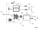
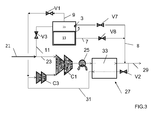
- Figures 2 and 3 illustrate different operation modes of a carbon dioxide liquefier with an integrated storage device as shown in Figure 1
- Figure 4 shows a phase diagram for carbon dioxide
- Figures 5 and 6 show different process modes for a carbon dioxide liquefier.
- storage vessel 5 is a reservoir containing no means for mass exchange, such as packing, trays etc.
- the storage vessel is shown schematically and may be cylindrical in form.
- the vessel has a liquid outlet in a lower region, here in the base of the vessel. It has a gas outlet in an upper region, here in the roof of the vessel. It also has a gas inlet and a liquid inlet in the upper region.
- the liquid inlet is formed by an orifice such that when the liquid carbon dioxide is introduced into the vessel, solid carbon dioxide is formed.
- liquid carbon dioxide 1 is sent to the vessel 5 via orifice 3.
- the liquid carbon dioxide contains at least 30% carbon dioxide, preferably at least 60% carbon dioxide.
- the liquid 1 is at a pressure of 5.5 bars abs and a temperature of -55°C for a carbon dioxide purity higher than 99.9%.
- the pressure is at 5 bars abs and gaseous carbon dioxide 15 is formed in the upper region leaving solid carbon dioxide 13 in the lower region.
- no carbon dioxide is removed via the liquid outlet 7 and no gas 11 is introduced via the gas inlet.
- some gas 9 may be removed by opening valve V1. This mode of operation is called "storage mode".
- the vessel 5 can be kept at a carbon dioxide partial pressure equal to the triple point pressure (5.11 atm) and the injection of liquid through does not directly produce solid.
- solid is formed from the liquid in the tank by extraction of gas in the vessel.
- the gas extraction is controlled by flow control means (typically a downstream compressor will impose the flow).
- the operating pressure may decrease to at most 1 bar below the triple point for the partial pressure of the carbon dioxide.
- carbon dioxide gas 11 is sent to the gas inlet at a pressure of 5.5 bars and saturation temperature. This causes some of the solid to melt, such that the three phases of carbon dioxide are simultaneously present in the vessel, which is under triple point conditions for the partial pressure of the carbon dioxide. No gas 9 is removed from the gas outlet but liquid 7 is removed from the lower region of the vessel 5. This mode of operation is called "release mode". The operating pressure may increase to at most 2 bar above the triple point for the partial pressure of the carbon dioxide.
- a variable gaseous carbon dioxide feed 21 is to be liquefied.
- Two modes of operation are possible, depending on the amount of feed 21.
- the feed 21 is low, all the feed is sent to compressor C1 as stream 23, compressed to a pressure of 75 bar abs, cooled in cooler 25 to form stream 33 and further cooled in heat exchanger 33 so as to be liquefied.
- Heat exchanger 27 may be of the plate fin type. Part of the liquid formed is removed as product 29. Another fraction 31 is expanded in valve V2 to produce refrigeration, warmed in heat exchanger 27 and compressed in recycle compressor C3, before being sent to the inlet of compressor C1.
- the rest 1 of the liquid is sent to the storage vessel 5 to be stored via conduit 8 and valve V7.
- the liquid 1 is expanded in orifice 3 and thereby partially frozen, forming solid carbon dioxide 13 and gaseous carbon dioxide 15.
- the gaseous carbon dioxide 9 is removed from the gas outlet in the top of the storage vessel via valve V1 and also sent to the recycle compressor C3.
- This mode of operation is called "storage mode”.
- FIG 3 there is a high flow gaseous carbon dioxide feed 21 which is divided in two. Part 23 is sent to compressor C1 as stream 23, compressed to a pressure of 75 bar abs, cooled in cooler 25 to form stream 33 and further cooled in heat exchanger 33 so as to be liquefied. Heat exchanger 27 may be of the plate fin type. Part of the liquid formed is removed as product 29. Another fraction 31 is expanded in valve V2 to produce refrigeration, warmed in heat exchanger 27 and compressed in recycle compressor C3, before being sent to the inlet of compressor C1.
- Another part 11 of the feed is sent in gaseous form via valve V3 to the storage vessel 5, thereby causing at least part of the solid carbon dioxide to melt.
- the liquid carbon dioxide 7 is removed from the liquid outlet (here in the side of the vessel) via valve V8 and added to the liquid formed in exchanger 27 via conduit 8, thereby forming part of the product 29.
- This mode of operation is called "release mode".
- release mode Thus more liquid carbon dioxide product 29 is produced in the mode of Figure 3 than in the mode of Figure 2 .
- Figure 4 shows the triple point at 5.11 atm and -56.6°C.
- the liquid is sent to the storage vessel, solidified and the solid is stored, whilst gas is removed.
- the release mode as shown in Figure 3 , gas is sent to the storage vessel, thereby causing the solid to melt and providing liquid to be removed from the storage vessel.
- Figures 5 and 6 show a slightly more complex liquefier in which there is additionally a separation step.
- the liquid need not be pumped and the product may be produced in gaseous form, upstream or downstream of the compressor CP.
- the apparatus is still considered to be a liquefier since a liquid is formed therein.
- no fluid is sent to or from storage vessel 5, the pump P2 is not operational and the recycle 63 is not operational.
- the gas 41 When the flue gas feed 41 is high, the gas 41 is sent to compressor C in which it is compressed, the compressed gas being then cooled in heat exchanger 43 within cold box 45. The gas is thereby partially condensed and is sent to a phase separator 49. The gas formed 59 in the phase separator is warmed in the heat exchanger 43 and removed as non-condensable gas.
- the liquid 51 is divided in two. Part 53 is expanded in valve V4, vaporized in heat exchanger 43, compressed in product compressor CP, cooled in cooler 25 to its liquefaction point and then compressed by pump P1 to form a supercritical liquid carbon dioxide product. Of course other product pressures are possible.
- the liquid need not be pumped and the product may be produced in gaseous form, upstream or downstream of the compressor CP. In this case, the apparatus is still considered to be a liquefier since a liquid is formed therein.
- Recycle 63 sends part of the liquid from cooler 25 back to exchanger 43 and to the phase separator via conduit 57
- Part 1 of the liquid from phase separator 49 is sent to the storage vessel 5 via valve V9. It expands through orifice 3 to form solid carbon dioxide 13 and gaseous carbon dioxide 15.
- Gas 9 is removed from the storage vessel via valve V1 and is warmed and sent to product compressor CP. No liquid is removed and no gas is sent to the vessel. Thus solid carbon dioxide accumulates in the storage vessel.
- the pump P2 is not operational. This mode of operation is called "storage mode".
- Part 11 of the gas 65 formed by vaporizing liquid from the phase separator is sent via valve V11 to the storage vessel 5. Sent into the vessel, it causes the solid carbon dioxide to liquefy and liquid 7 is removed from the storage vessel 5 via valve V10. No liquid 1 is sent to the vessel and no gas 9 is removed therefrom. The liquid 9 is sent back to the phase separator. To vaporize this increased amount of liquid, it may be possible to send all the liquid 51 from the phase separator 49 to valve V4 and vaporize it at a single pressure.
- Figure 6 shows the option where part of the liquid is vaporized in this way and then rest 55 is sent via valve V6 to second pump P2, pumped to a higher pressure, then heated through heat exchanger 43 and produced as a supercritical CO2 stream to be further pumped through pump P1. ...
- the recycle 63 is not operational and so is not shown to simplify the figure and no liquid flows in conduit 57.
- This mode of operation is called "release mode”.
- the modes of operation described in Figures 2 and 3 and in Figures 5 and 6 are described in the context of using the storage mode when flowrate of feed gas is higher than a first given value and using the release mode when flowrate of feed gas is below a second given value, equal to or lower than the first given value.
- the storage mode may be used if the demand for liquid rich in carbon dioxide or gas derived therefrom is lower than a first given value. If the demand for liquid rich in carbon dioxide or gas derived therefrom is higher than a second given value, equal to or higher than the first given value, the release mode may be used.
- the storage mode may be used when the cost of electricity is below a first given value and the release mode may be used when the cost of electricity is above a second given value, equal to or higher than the first given value.
Landscapes
- Engineering & Computer Science (AREA)
- Physics & Mathematics (AREA)
- Mechanical Engineering (AREA)
- Thermal Sciences (AREA)
- General Engineering & Computer Science (AREA)
- Chemical & Material Sciences (AREA)
- Chemical Kinetics & Catalysis (AREA)
- Organic Chemistry (AREA)
- Inorganic Chemistry (AREA)
- Carbon And Carbon Compounds (AREA)
- Separation By Low-Temperature Treatments (AREA)
Abstract
Description
- The present invention relates to a process for storing liquid rich in carbon dioxide in solid form.
- It is frequently desirable to store liquid rich in carbon dioxide, a liquid rich in carbon dioxide being defined as containing at least 30% carbon dioxide, preferably at least 60% carbon dioxide.
- For example, in the case of a network extracting gas rich in carbon dioxide from various sources wherein the gas is liquefied and then supplied to a consumer, the consumer may have varying requirements and may not require all the liquid rich in carbon dioxide all the time.
- It is expensive to store the gas rich in carbon dioxide under pressure and the size of the storage vessels is limited.
- The present invention provides a dense phase storage which reduces both footprint and energy.
- According to the present invention, there is provided a process for storing liquid rich in carbon dioxide in solid form and subsequently releasing liquid containing mainly carbon dioxide including the following steps:
- a) a solid containing mainly carbon dioxide is formed from at least part of the liquid with or without using indirect heat exchange means,
- b) storing the solid containing mainly carbon dioxide,
- c) subsequently causing at least part of the solid containing mainly carbon dioxide to melt forming a liquid containing mainly carbon dioxide, by direct contact with an auxiliary gas rich in carbon dioxide, wherein the auxiliary gas is at least partially liquefied to form liquid containing mainly carbon dioxide by heat exchange with the melting solid, and
- d) during at least part of step c) removing at least part of the liquid containing mainly carbon dioxide.
- According to other optional aspects of the invention:
- the operating pressure is such that the carbon dioxide has a partial pressure no more than 1 bar lower than the triple point pressure of CO2 during phase b) and no more than 2 bars higher than the triple point pressure during phase c) and wherein during step a), a solid is formed within a vessel by extracting gas from the vessel, the flowrate of gas extracted from the vessel being is strictly superior to the sum of any gas injected into the equipment due to direct gas injection and or partial flash of liquid inlet linked to the pressure reduction) and of any gas generated by external heating by evaporation of the liquid and/or sublimation of the solid.
- step a. takes place without indirect heat exchange, the liquid rich in carbon dioxide, having a partial pressure for carbon dioxide higher than the triple point pressure, is expanded to a pressure such that the partial pressure for carbon dioxide is lower than the triple point pressure, so as to form a solid containing mainly carbon dioxide and a gas having a reduced content of carbon dioxide.
- the solid is formed in a vessel and the gas rich in carbon dioxide is sent to the vessel.
- the solid is formed in a first vessel, then transferred to a second vessel into which the gas rich in carbon dioxide is introduced, the storing of the carbon dioxide taking place in the first vessel and/or the second vessel.
- the solid is formed in a first vessel, then transferred to a second vessel to be stored and then transferred to a third vessel into which the gas rich in carbon dioxide is introduced.
- the solid is formed in a first vessel, then transferred to a second vessel to be stored and then transferred back to the first vessel into which the gas rich in carbon dioxide is introduced.
- The invention also relates to a process for liquefying a feed gas rich in carbon dioxide wherein at least part of the feed gas is at least partially liquefied by cooling to form a liquid rich in carbon dioxide in which:
- during at least a first period
- i) a solid containing mainly carbon dioxide is formed from at least part of the liquid with or without using indirect heat exchange means
- ii) storing the solid containing mainly carbon dioxide and
- during at least a second period
- iii) causing at least part of the solid containing mainly carbon dioxide to melt forming a liquid containing mainly carbon dioxide, by direct contact with an auxiliary gas rich in carbon dioxide, wherein the auxiliary gas is at least partially liquefied to form liquid containing mainly carbon dioxide by heat exchange with the melting solid and
- iv) during at least part of step iii) removing at least part of the liquid containing mainly carbon dioxide.
- According to other optional features of the invention
- only part of the liquid rich in carbon dioxide is expanded during the first period, the rest of the liquid rich in carbon dioxide being removed as a product or vaporized to form a gaseous product during the first period and/or the second period.
- the first period corresponds to a period when at least one of the following conditions holds:
- a) where the demand for liquid rich in carbon dioxide or gas derived there from is less than that during the second period,
- b) where the cost of electricity during the first period is less than that during the second period,
- c) where the flowrate of feed gas rich in carbon dioxide during the first period is less than that during the second period.
- at least one of the first and second periods has a duration of less than 24 hours.
- the feed gas rich in carbon dioxide is a waste gas from an oxyfuel combustion process, a steelmaking process, a steam methane reforming process, a gasification process, an ammonia process, an ethanol plant.
- the feed gas rich in carbon dioxide is coming from at least two sources including but not limited to waste gas from at least one oxyfuel combustion process, at least one steelmaking process, at least one steam methane reforming process, at least one gasification process, at least one ammonia manufacturing process, at least one ethanol plant.
- the process comprises purifying the liquid containing carbon dioxide.
- the process comprises vaporizing the liquid containing carbon dioxide and compressing the gas formed.
- The invention will be described in greater detail with reference to the figures.
-
Figure 1 illustrates a storage device for carbon dioxide,Figures 2 and3 illustrate different operation modes of a carbon dioxide liquefier with an integrated storage device as shown inFigure 1 ,Figure 4 shows a phase diagram for carbon dioxide andFigures 5 and6 show different process modes for a carbon dioxide liquefier. - In
Figure 1 ,storage vessel 5 is a reservoir containing no means for mass exchange, such as packing, trays etc. The storage vessel is shown schematically and may be cylindrical in form. The vessel has a liquid outlet in a lower region, here in the base of the vessel. It has a gas outlet in an upper region, here in the roof of the vessel. It also has a gas inlet and a liquid inlet in the upper region. The liquid inlet is formed by an orifice such that when the liquid carbon dioxide is introduced into the vessel, solid carbon dioxide is formed. - In a typical case,
liquid carbon dioxide 1 is sent to thevessel 5 viaorifice 3. The liquid carbon dioxide contains at least 30% carbon dioxide, preferably at least 60% carbon dioxide. Theliquid 1 is at a pressure of 5.5 bars abs and a temperature of -55°C for a carbon dioxide purity higher than 99.9%. Within thevessel 5 the pressure is at 5 bars abs andgaseous carbon dioxide 15 is formed in the upper region leavingsolid carbon dioxide 13 in the lower region. In order to store energy, no carbon dioxide is removed via theliquid outlet 7 and nogas 11 is introduced via the gas inlet. In order to control the pressure, somegas 9 may be removed by opening valve V1. This mode of operation is called "storage mode". - Alternatively, during the "storage mode", the
vessel 5 can be kept at a carbon dioxide partial pressure equal to the triple point pressure (5.11 atm) and the injection of liquid through does not directly produce solid. In this alternative, solid is formed from the liquid in the tank by extraction of gas in the vessel. The gas extraction is controlled by flow control means (typically a downstream compressor will impose the flow). The operating pressure may decrease to at most 1 bar below the triple point for the partial pressure of the carbon dioxide. - In order to release energy, when no
liquid 1 is sent to the vessel,carbon dioxide gas 11 is sent to the gas inlet at a pressure of 5.5 bars and saturation temperature. This causes some of the solid to melt, such that the three phases of carbon dioxide are simultaneously present in the vessel, which is under triple point conditions for the partial pressure of the carbon dioxide. Nogas 9 is removed from the gas outlet butliquid 7 is removed from the lower region of thevessel 5. This mode of operation is called "release mode". The operating pressure may increase to at most 2 bar above the triple point for the partial pressure of the carbon dioxide. - In
Figures 2 and3 , a variable gaseouscarbon dioxide feed 21 is to be liquefied. Two modes of operation are possible, depending on the amount offeed 21. InFigure 2 , thefeed 21 is low, all the feed is sent to compressor C1 asstream 23, compressed to a pressure of 75 bar abs, cooled incooler 25 to formstream 33 and further cooled inheat exchanger 33 so as to be liquefied.Heat exchanger 27 may be of the plate fin type. Part of the liquid formed is removed asproduct 29. Anotherfraction 31 is expanded in valve V2 to produce refrigeration, warmed inheat exchanger 27 and compressed in recycle compressor C3, before being sent to the inlet of compressor C1. Therest 1 of the liquid is sent to thestorage vessel 5 to be stored viaconduit 8 and valve V7. Theliquid 1 is expanded inorifice 3 and thereby partially frozen, formingsolid carbon dioxide 13 andgaseous carbon dioxide 15. Thegaseous carbon dioxide 9 is removed from the gas outlet in the top of the storage vessel via valve V1 and also sent to the recycle compressor C3. Thus the carbon dioxide is stored with the storage vessel in solid form. This mode of operation is called "storage mode". - In
Figure 3 , there is a high flow gaseous carbon dioxide feed 21 which is divided in two.Part 23 is sent to compressor C1 asstream 23, compressed to a pressure of 75 bar abs, cooled in cooler 25 to formstream 33 and further cooled inheat exchanger 33 so as to be liquefied.Heat exchanger 27 may be of the plate fin type. Part of the liquid formed is removed asproduct 29. Anotherfraction 31 is expanded in valve V2 to produce refrigeration, warmed inheat exchanger 27 and compressed in recycle compressor C3, before being sent to the inlet of compressor C1. - Another
part 11 of the feed is sent in gaseous form via valve V3 to thestorage vessel 5, thereby causing at least part of the solid carbon dioxide to melt. Theliquid carbon dioxide 7 is removed from the liquid outlet (here in the side of the vessel) via valve V8 and added to the liquid formed inexchanger 27 viaconduit 8, thereby forming part of theproduct 29. This mode of operation is called "release mode". Thus more liquidcarbon dioxide product 29 is produced in the mode ofFigure 3 than in the mode ofFigure 2 . -
Figure 4 shows the triple point at 5.11 atm and -56.6°C. In the storage mode, as shown inFigure 2 , the liquid is sent to the storage vessel, solidified and the solid is stored, whilst gas is removed. In the release mode, as shown inFigure 3 , gas is sent to the storage vessel, thereby causing the solid to melt and providing liquid to be removed from the storage vessel. -
Figures 5 and6 show a slightly more complex liquefier in which there is additionally a separation step. - Under normal operation, the process of
Figure 5 operates as follows.Flue gas 41 or any gas rich in carbon dioxide is sent to a compressor C in which it is compressed, the compressed gas being then cooled inheat exchanger 43 within acold box 45. The gas is thereby partially condensed and is sent to aphase separator 49. The gas formed 59 is warmed in theheat exchanger 43 and removed as non-condensable gas. The liquid 51 is expanded in valve V4, vaporized inheat exchanger 43, compressed in product compressor CP, cooled in cooler 25 to its liquefaction point and then compressed by pump P1 to form a supercritical liquid carbon dioxide product. Of course other product pressures are possible. The liquid need not be pumped and the product may be produced in gaseous form, upstream or downstream of the compressor CP. In this case, the apparatus is still considered to be a liquefier since a liquid is formed therein. In this case, no fluid is sent to or fromstorage vessel 5, the pump P2 is not operational and therecycle 63 is not operational. - When the
flue gas feed 41 is high, thegas 41 is sent to compressor C in which it is compressed, the compressed gas being then cooled inheat exchanger 43 withincold box 45. The gas is thereby partially condensed and is sent to aphase separator 49. The gas formed 59 in the phase separator is warmed in theheat exchanger 43 and removed as non-condensable gas. The liquid 51 is divided in two.Part 53 is expanded in valve V4, vaporized inheat exchanger 43, compressed in product compressor CP, cooled in cooler 25 to its liquefaction point and then compressed by pump P1 to form a supercritical liquid carbon dioxide product. Of course other product pressures are possible. The liquid need not be pumped and the product may be produced in gaseous form, upstream or downstream of the compressor CP. In this case, the apparatus is still considered to be a liquefier since a liquid is formed therein.Recycle 63 sends part of the liquid from cooler 25 back toexchanger 43 and to the phase separator viaconduit 57. -
Part 1 of the liquid fromphase separator 49 is sent to thestorage vessel 5 via valve V9. It expands throughorifice 3 to formsolid carbon dioxide 13 andgaseous carbon dioxide 15.Gas 9 is removed from the storage vessel via valve V1 and is warmed and sent to product compressor CP. No liquid is removed and no gas is sent to the vessel. Thus solid carbon dioxide accumulates in the storage vessel. - In this case, the pump P2 is not operational. This mode of operation is called "storage mode".
- In
Figure 6 , the amount of gas to be liquefied is reduced.Flue gas 41 or any gas rich in carbon dioxide is sent to compressor C in which it is compressed, the compressed gas being then cooled inheat exchanger 43 withincold box 45. The gas is thereby partially condensed and is sent entirely to phaseseparator 49. The gas formed 59 is warmed in theheat exchanger 43 and removed as non-condensable gas. The liquid 51 is expanded in valve V4, vaporized inheat exchanger 43 to formgas 65, compressed in part in product compressor CP, cooled in cooler 25 to its liquefaction point and then compressed by pump P1 to form a supercritical liquid carbon dioxide product. Of course other product pressures are possible. The liquid need not be pumped and the product may be produced in gaseous form, upstream or downstream of the compressor CP. In this case, the apparatus is still considered to be a liquefier since a liquid is formed therein. -
Part 11 of thegas 65 formed by vaporizing liquid from the phase separator is sent via valve V11 to thestorage vessel 5. Sent into the vessel, it causes the solid carbon dioxide to liquefy andliquid 7 is removed from thestorage vessel 5 via valve V10. Noliquid 1 is sent to the vessel and nogas 9 is removed therefrom. Theliquid 9 is sent back to the phase separator. To vaporize this increased amount of liquid, it may be possible to send all the liquid 51 from thephase separator 49 to valve V4 and vaporize it at a single pressure. HoweverFigure 6 shows the option where part of the liquid is vaporized in this way and then rest 55 is sent via valve V6 to second pump P2, pumped to a higher pressure, then heated throughheat exchanger 43 and produced as a supercritical CO2 stream to be further pumped through pump P1. ... - The
recycle 63 is not operational and so is not shown to simplify the figure and no liquid flows inconduit 57. - This mode of operation is called "release mode".
- The modes of operation described in
Figures 2 and3 and inFigures 5 and6 are described in the context of using the storage mode when flowrate of feed gas is higher than a first given value and using the release mode when flowrate of feed gas is below a second given value, equal to or lower than the first given value. However other criteria may be used to determine when the storage and release modes may be used. For example, if the demand for liquid rich in carbon dioxide or gas derived therefrom is lower than a first given value, the storage mode may be used. If the demand for liquid rich in carbon dioxide or gas derived therefrom is higher than a second given value, equal to or higher than the first given value, the release mode may be used. Alternatively, the storage mode may be used when the cost of electricity is below a first given value and the release mode may be used when the cost of electricity is above a second given value, equal to or higher than the first given value.
Claims (15)
- Process for storing liquid rich in carbon dioxide in solid form and subsequently releasing liquid containing mainly carbon dioxide including the following steps:a) a solid (13) containing mainly carbon dioxide is formed from at least part of the liquid (1) with or without using indirect heat exchange meansb) storing the solid containing mainly carbon dioxidec) subsequently causing at least part of the solid containing mainly carbon dioxide to melt forming a liquid containing mainly carbon dioxide, by direct contact with an auxiliary gas (11) rich in carbon dioxide, wherein the auxiliary gas is at least partially liquefied to form liquid containing mainly carbon dioxide by heat exchange with the melting solid andd) during at least part of step c) removing at least part of the liquid (7) containing mainly carbon dioxide.
- Process according to claim 1, where the operating pressure is such that the carbon dioxide has a partial pressure no more than 1 bar lower than the triple point pressure of CO2 during phase b) and no more than 2 bars higher than the triple point pressure during phase c) and wherein during step a), a solid is formed within a vessel (5) by extracting gas from the vessel, the flowrate of gas extracted from the vessel being is strictly superior to the sum of any gas injected into the equipment by direct gas injection or partial flash of liquid inlet linked to the pressure reduction and any gas generated by external heating by evaporation of the liquid and sublimation of the solid.
- Process according to claim 1, wherein step a. takes place without indirect heat exchange, the liquid rich in carbon dioxide, having a partial pressure for carbon dioxide higher than the triple point pressure, is expanded to a pressure such that the partial pressure for carbon dioxide is lower than the triple point pressure, so as to form a solid containing mainly carbon dioxide and a gas having a reduced content of carbon dioxide.
- Process according to at least one of Claims 1 to 3, wherein the solid is formed in a vessel (5) and the gas (11) rich in carbon dioxide is sent to the vessel.
- Process according to at least one of Claims 1 to 3, wherein the solid is formed in a first vessel, then transferred to a second vessel into which the gas rich in carbon dioxide is introduced, the storing of the carbon dioxide taking place in the first vessel and/or the second vessel.
- Process according to at least one of Claim 1 to 3 or 5, wherein the solid is formed in a first vessel, then transferred to a second vessel to be stored and then transferred to a third vessel into which the gas rich in carbon dioxide is introduced
- Process according to at least one of Claims 1 to 3, wherein the solid is formed in a first vessel, then transferred to a second vessel to be stored and then transferred back to the first vessel into which the gas rich in carbon dioxide is introduced.
- Process for liquefying a feed gas rich in carbon dioxide wherein at least part of the feed gas (11, 21,41) is at least partially liquefied by cooling to form a liquid rich in carbon dioxide in which:- during at least a first periodi) a solid (13) containing mainly carbon dioxide is formed from at least part of the liquid (1) with or without using indirect heat exchange meansii) storing the solid containing mainly carbon dioxide and- during at least a second periodiii) causing at least part of the solid containing mainly carbon dioxide to melt forming a liquid containing mainly carbon dioxide, by direct contact with an auxiliary gas (11) rich in carbon dioxide, wherein the auxiliary gas is at least partially liquefied to form liquid containing mainly carbon dioxide by heat exchange with the melting solid andiv) during at least part of step iii) removing at least part of the liquid (7) containing mainly carbon dioxide.
- Process according to Claim 8, wherein only part of the liquid (1) rich in carbon dioxide is expanded during the first period, the rest of the liquid rich in carbon dioxide being removed as a product or vaporized to form a gaseous product during the first period and/or the second period.
- Process according to Claim 8 or 9, wherein the first period corresponds to a period when at least one of the following conditions holds:a) where the demand for liquid rich in carbon dioxide or gas derived there from is less than that during the second period,b) where the cost of electricity during the first period is less than that during the second period,c) where the flowrate of feed gas (11, 21,41) rich in carbon dioxide during the first period is less than that during the second period.
- Process according to one of claims 8 to 10, where at least one of the first and second periods has a duration of less than 24 hours.
- Process according to one of Claims 1 to 11, wherein the feed gas rich in carbon dioxide (11, 21,41) is a waste gas from an oxyfuel combustion process, a steelmaking process, a steam methane reforming process, a gasification process, an ammonia process or an ethanol plant.
- Process according to one of Claims 1 to 12, where the feed gas rich in carbon dioxide (11, 21,41) is coming from at least two sources including but not limited to waste gas from at least one oxyfuel combustion process, at least one steelmaking process, at least one steam methane reforming process, at least one gasification process, at least one ammonia manufacturing process, at least one ethanol plant.
- Process according to claim 1 to 13, comprising purifying the liquid (7) containing carbon dioxide.
- Process according to claim 1 to 14, comprising vaporizing the liquid (55) containing carbon dioxide and compressing the gas thereby formed.
Priority Applications (7)
| Application Number | Priority Date | Filing Date | Title |
|---|---|---|---|
| EP12305847.1A EP2685189A1 (en) | 2012-07-13 | 2012-07-13 | Process for storing liquid rich in carbon dioxide in solid form |
| US14/413,661 US20150176892A1 (en) | 2012-07-13 | 2013-07-12 | Process for storing liquid rich in carbon dioxide in solid form |
| EP13739640.4A EP2872839A1 (en) | 2012-07-13 | 2013-07-12 | Process for storing liquid rich in carbon dioxide in solid form |
| AU2013288574A AU2013288574A1 (en) | 2012-07-13 | 2013-07-12 | Process for storing liquid rich in carbon dioxide in solid form |
| CN201380037309.1A CN104471333B (en) | 2012-07-13 | 2013-07-12 | Method for storing carbon dioxide enriched liquid in solid form |
| PCT/EP2013/064855 WO2014009559A1 (en) | 2012-07-13 | 2013-07-12 | Process for storing liquid rich in carbon dioxide in solid form |
| CA2875805A CA2875805A1 (en) | 2012-07-13 | 2013-07-12 | Process for storing liquid rich in carbon dioxide in solid form |
Applications Claiming Priority (1)
| Application Number | Priority Date | Filing Date | Title |
|---|---|---|---|
| EP12305847.1A EP2685189A1 (en) | 2012-07-13 | 2012-07-13 | Process for storing liquid rich in carbon dioxide in solid form |
Publications (1)
| Publication Number | Publication Date |
|---|---|
| EP2685189A1 true EP2685189A1 (en) | 2014-01-15 |
Family
ID=48832885
Family Applications (2)
| Application Number | Title | Priority Date | Filing Date |
|---|---|---|---|
| EP12305847.1A Withdrawn EP2685189A1 (en) | 2012-07-13 | 2012-07-13 | Process for storing liquid rich in carbon dioxide in solid form |
| EP13739640.4A Withdrawn EP2872839A1 (en) | 2012-07-13 | 2013-07-12 | Process for storing liquid rich in carbon dioxide in solid form |
Family Applications After (1)
| Application Number | Title | Priority Date | Filing Date |
|---|---|---|---|
| EP13739640.4A Withdrawn EP2872839A1 (en) | 2012-07-13 | 2013-07-12 | Process for storing liquid rich in carbon dioxide in solid form |
Country Status (6)
| Country | Link |
|---|---|
| US (1) | US20150176892A1 (en) |
| EP (2) | EP2685189A1 (en) |
| CN (1) | CN104471333B (en) |
| AU (1) | AU2013288574A1 (en) |
| CA (1) | CA2875805A1 (en) |
| WO (1) | WO2014009559A1 (en) |
Cited By (2)
| Publication number | Priority date | Publication date | Assignee | Title |
|---|---|---|---|---|
| WO2016064267A1 (en) * | 2014-10-20 | 2016-04-28 | Haffmans B.V. | A process installation for preparing a carbon dioxide (co2) end product from a gaseous carbon dioxide containing starting product |
| WO2018101996A1 (en) * | 2016-12-02 | 2018-06-07 | General Electric Company | Method and system for carbon dioxide energy storage in a power generation system |
Families Citing this family (5)
| Publication number | Priority date | Publication date | Assignee | Title |
|---|---|---|---|---|
| US11022369B2 (en) * | 2016-02-09 | 2021-06-01 | Mitsubishi Heavy Industries Compressor Corporation | Booster system |
| US20190170441A1 (en) * | 2017-12-05 | 2019-06-06 | Larry Baxter | Pressure-Regulated Melting of Solids with Warm Fluids |
| US20190170440A1 (en) * | 2017-12-05 | 2019-06-06 | Larry Baxter | Pressure-Regulated Melting of Solids |
| US11352262B2 (en) * | 2017-12-18 | 2022-06-07 | Praxair Technology, Inc. | Methods for automatic filling, charging and dispensing carbon dioxide snow block |
| IT202300018708A1 (en) * | 2023-09-12 | 2025-03-12 | Snf Envirotech Srl | CARBON SNOW PRODUCTION SYSTEM AND METHOD |
Citations (4)
| Publication number | Priority date | Publication date | Assignee | Title |
|---|---|---|---|---|
| EP0277777A2 (en) * | 1987-02-04 | 1988-08-10 | CBI Research Corporation | Power plant using CO2 as a working fluid |
| JPH0317490A (en) * | 1989-06-15 | 1991-01-25 | Mitsubishi Heavy Ind Ltd | Production method of liquefied co2 |
| WO2005105669A1 (en) * | 2004-04-27 | 2005-11-10 | Institut Francais Du Petrole | Method for liquefying solid carbon dioxide |
| GB2416389A (en) * | 2004-07-16 | 2006-01-25 | Statoil Asa | Multi-step cooling and compression to form liquid carbon dioxide |
Family Cites Families (3)
| Publication number | Priority date | Publication date | Assignee | Title |
|---|---|---|---|---|
| FR1030463A (en) * | 1950-01-20 | 1953-06-15 | Pergine Soc It Per L Ind Dell | Method and apparatus for the preservation of solidified carbon dioxide and similar products |
| US4995234A (en) * | 1989-10-02 | 1991-02-26 | Chicago Bridge & Iron Technical Services Company | Power generation from LNG |
| EP2496901A4 (en) * | 2009-11-02 | 2013-04-24 | Exxonmobil Upstream Res Co | Cryogenic system for removing acid gases from a hydrocarbon gas stream, with removal of hydrogen sulfide |
-
2012
- 2012-07-13 EP EP12305847.1A patent/EP2685189A1/en not_active Withdrawn
-
2013
- 2013-07-12 US US14/413,661 patent/US20150176892A1/en not_active Abandoned
- 2013-07-12 CN CN201380037309.1A patent/CN104471333B/en active Active
- 2013-07-12 CA CA2875805A patent/CA2875805A1/en not_active Abandoned
- 2013-07-12 EP EP13739640.4A patent/EP2872839A1/en not_active Withdrawn
- 2013-07-12 WO PCT/EP2013/064855 patent/WO2014009559A1/en not_active Ceased
- 2013-07-12 AU AU2013288574A patent/AU2013288574A1/en not_active Abandoned
Patent Citations (4)
| Publication number | Priority date | Publication date | Assignee | Title |
|---|---|---|---|---|
| EP0277777A2 (en) * | 1987-02-04 | 1988-08-10 | CBI Research Corporation | Power plant using CO2 as a working fluid |
| JPH0317490A (en) * | 1989-06-15 | 1991-01-25 | Mitsubishi Heavy Ind Ltd | Production method of liquefied co2 |
| WO2005105669A1 (en) * | 2004-04-27 | 2005-11-10 | Institut Francais Du Petrole | Method for liquefying solid carbon dioxide |
| GB2416389A (en) * | 2004-07-16 | 2006-01-25 | Statoil Asa | Multi-step cooling and compression to form liquid carbon dioxide |
Cited By (3)
| Publication number | Priority date | Publication date | Assignee | Title |
|---|---|---|---|---|
| WO2016064267A1 (en) * | 2014-10-20 | 2016-04-28 | Haffmans B.V. | A process installation for preparing a carbon dioxide (co2) end product from a gaseous carbon dioxide containing starting product |
| NL2013653B1 (en) * | 2014-10-20 | 2016-10-04 | Haffmans Bv | A process installation for preparing a carbon dioxide (CO2) end product from a gaseous carbon dioxide containing starting product. |
| WO2018101996A1 (en) * | 2016-12-02 | 2018-06-07 | General Electric Company | Method and system for carbon dioxide energy storage in a power generation system |
Also Published As
| Publication number | Publication date |
|---|---|
| CA2875805A1 (en) | 2014-01-16 |
| CN104471333A (en) | 2015-03-25 |
| EP2872839A1 (en) | 2015-05-20 |
| WO2014009559A1 (en) | 2014-01-16 |
| US20150176892A1 (en) | 2015-06-25 |
| CN104471333B (en) | 2017-10-10 |
| AU2013288574A1 (en) | 2015-01-29 |
Similar Documents
| Publication | Publication Date | Title |
|---|---|---|
| EP2685189A1 (en) | Process for storing liquid rich in carbon dioxide in solid form | |
| EP2229567B1 (en) | Method for regulation of cooling capacity of a cooling system based on a gas expansion process. | |
| CN105043014B (en) | Denitrogenated using integrated in the liquefied natural gas (LNG) production in special fill-before-fire loop | |
| CA2550947A1 (en) | Cryogenic air separation process and apparatus | |
| TW201213692A (en) | Integrated liquid storage | |
| JP2015210077A (en) | Integrated nitrogen removal in the production of liquefied natural gas using intermediate feed gas separation | |
| TWI628401B (en) | Verfahren und vorrichtung zur sauerstoffgewinnung durch tieftemperaturzerlegung von luft mit variablem energieverbrauch | |
| US20100126215A1 (en) | Method For Cooling A Cryogenic Exchange Line | |
| TW201730493A (en) | Method for obtaining air products in an air separation plant and air separation plant | |
| CN105008835B (en) | Separation includes carbon dioxide and the gaseous mixture compared with light impurity at a temperature below ambient | |
| TWI270644B (en) | Air separator and operating method thereof | |
| CA3210125A1 (en) | Method for liquefying a stream rich in co2 | |
| US8713964B2 (en) | Method and device for separating a gas mixture by cryogenic distillation | |
| AU2013289279B2 (en) | Process for the separation of a gas rich in carbon dioxide | |
| US20230184380A1 (en) | Fuel-gas supply system and method for supplying a high-pressure gas injection engine with fuel gas | |
| CN104011488B (en) | Method and apparatus for supplying gaseous carbon monoxide by cryogenic distillation | |
| EP4579164A2 (en) | Device for methane liquefaction | |
| JP2003021456A (en) | Internal pressurized cold air separator | |
| CN109520207A (en) | For passing through the method and unit of separating air by cryogenic distillation |
Legal Events
| Date | Code | Title | Description |
|---|---|---|---|
| PUAI | Public reference made under article 153(3) epc to a published international application that has entered the european phase |
Free format text: ORIGINAL CODE: 0009012 |
|
| AK | Designated contracting states |
Kind code of ref document: A1 Designated state(s): AL AT BE BG CH CY CZ DE DK EE ES FI FR GB GR HR HU IE IS IT LI LT LU LV MC MK MT NL NO PL PT RO RS SE SI SK SM TR |
|
| AX | Request for extension of the european patent |
Extension state: BA ME |
|
| 17P | Request for examination filed |
Effective date: 20140715 |
|
| RBV | Designated contracting states (corrected) |
Designated state(s): AL AT BE BG CH CY CZ DE DK EE ES FI FR GB GR HR HU IE IS IT LI LT LU LV MC MK MT NL NO PL PT RO RS SE SI SK SM TR |
|
| 17Q | First examination report despatched |
Effective date: 20160324 |
|
| STAA | Information on the status of an ep patent application or granted ep patent |
Free format text: STATUS: THE APPLICATION HAS BEEN WITHDRAWN |
|
| 18W | Application withdrawn |
Effective date: 20160926 |