EP2229567B1 - Method for regulation of cooling capacity of a cooling system based on a gas expansion process. - Google Patents
Method for regulation of cooling capacity of a cooling system based on a gas expansion process. Download PDFInfo
- Publication number
- EP2229567B1 EP2229567B1 EP08857460.3A EP08857460A EP2229567B1 EP 2229567 B1 EP2229567 B1 EP 2229567B1 EP 08857460 A EP08857460 A EP 08857460A EP 2229567 B1 EP2229567 B1 EP 2229567B1
- Authority
- EP
- European Patent Office
- Prior art keywords
- cooling
- cooling medium
- cooling circuit
- gas
- liquid
- Prior art date
- Legal status (The legal status is an assumption and is not a legal conclusion. Google has not performed a legal analysis and makes no representation as to the accuracy of the status listed.)
- Active
Links
- 238000001816 cooling Methods 0.000 title claims description 157
- 238000000034 method Methods 0.000 title claims description 48
- 239000002826 coolant Substances 0.000 claims description 132
- 239000007789 gas Substances 0.000 claims description 98
- 239000007788 liquid Substances 0.000 claims description 47
- 238000003860 storage Methods 0.000 claims description 30
- IJGRMHOSHXDMSA-UHFFFAOYSA-N Atomic nitrogen Chemical compound N#N IJGRMHOSHXDMSA-UHFFFAOYSA-N 0.000 claims description 17
- 229910052757 nitrogen Inorganic materials 0.000 claims description 9
- 230000006835 compression Effects 0.000 claims description 6
- 238000007906 compression Methods 0.000 claims description 6
- 238000001704 evaporation Methods 0.000 claims description 6
- 239000012530 fluid Substances 0.000 claims description 6
- 230000008020 evaporation Effects 0.000 claims description 5
- 238000004519 manufacturing process Methods 0.000 claims description 2
- 230000001105 regulatory effect Effects 0.000 claims description 2
- 239000003949 liquefied natural gas Substances 0.000 claims 2
- 238000009434 installation Methods 0.000 description 14
- VNWKTOKETHGBQD-UHFFFAOYSA-N methane Chemical compound C VNWKTOKETHGBQD-UHFFFAOYSA-N 0.000 description 14
- 239000012071 phase Substances 0.000 description 7
- 239000000203 mixture Substances 0.000 description 6
- 239000003345 natural gas Substances 0.000 description 6
- 238000000926 separation method Methods 0.000 description 4
- 238000010438 heat treatment Methods 0.000 description 3
- 229930195733 hydrocarbon Natural products 0.000 description 3
- 150000002430 hydrocarbons Chemical class 0.000 description 3
- 239000000112 cooling gas Substances 0.000 description 2
- 239000000284 extract Substances 0.000 description 2
- 239000011810 insulating material Substances 0.000 description 2
- 239000007791 liquid phase Substances 0.000 description 2
- 239000004215 Carbon black (E152) Substances 0.000 description 1
- 230000001276 controlling effect Effects 0.000 description 1
- 230000001419 dependent effect Effects 0.000 description 1
- 238000009413 insulation Methods 0.000 description 1
- 239000012774 insulation material Substances 0.000 description 1
- 238000012432 intermediate storage Methods 0.000 description 1
- QJGQUHMNIGDVPM-UHFFFAOYSA-N nitrogen group Chemical group [N] QJGQUHMNIGDVPM-UHFFFAOYSA-N 0.000 description 1
- 235000019362 perlite Nutrition 0.000 description 1
- 239000010451 perlite Substances 0.000 description 1
- 238000004064 recycling Methods 0.000 description 1
- 238000010792 warming Methods 0.000 description 1
Images


Classifications
-
- F—MECHANICAL ENGINEERING; LIGHTING; HEATING; WEAPONS; BLASTING
- F25—REFRIGERATION OR COOLING; COMBINED HEATING AND REFRIGERATION SYSTEMS; HEAT PUMP SYSTEMS; MANUFACTURE OR STORAGE OF ICE; LIQUEFACTION SOLIDIFICATION OF GASES
- F25J—LIQUEFACTION, SOLIDIFICATION OR SEPARATION OF GASES OR GASEOUS OR LIQUEFIED GASEOUS MIXTURES BY PRESSURE AND COLD TREATMENT OR BY BRINGING THEM INTO THE SUPERCRITICAL STATE
- F25J1/00—Processes or apparatus for liquefying or solidifying gases or gaseous mixtures
- F25J1/02—Processes or apparatus for liquefying or solidifying gases or gaseous mixtures requiring the use of refrigeration, e.g. of helium or hydrogen ; Details and kind of the refrigeration system used; Integration with other units or processes; Controlling aspects of the process
- F25J1/0228—Coupling of the liquefaction unit to other units or processes, so-called integrated processes
- F25J1/0235—Heat exchange integration
- F25J1/0236—Heat exchange integration providing refrigeration for different processes treating not the same feed stream
-
- F—MECHANICAL ENGINEERING; LIGHTING; HEATING; WEAPONS; BLASTING
- F25—REFRIGERATION OR COOLING; COMBINED HEATING AND REFRIGERATION SYSTEMS; HEAT PUMP SYSTEMS; MANUFACTURE OR STORAGE OF ICE; LIQUEFACTION SOLIDIFICATION OF GASES
- F25J—LIQUEFACTION, SOLIDIFICATION OR SEPARATION OF GASES OR GASEOUS OR LIQUEFIED GASEOUS MIXTURES BY PRESSURE AND COLD TREATMENT OR BY BRINGING THEM INTO THE SUPERCRITICAL STATE
- F25J1/00—Processes or apparatus for liquefying or solidifying gases or gaseous mixtures
- F25J1/02—Processes or apparatus for liquefying or solidifying gases or gaseous mixtures requiring the use of refrigeration, e.g. of helium or hydrogen ; Details and kind of the refrigeration system used; Integration with other units or processes; Controlling aspects of the process
-
- F—MECHANICAL ENGINEERING; LIGHTING; HEATING; WEAPONS; BLASTING
- F25—REFRIGERATION OR COOLING; COMBINED HEATING AND REFRIGERATION SYSTEMS; HEAT PUMP SYSTEMS; MANUFACTURE OR STORAGE OF ICE; LIQUEFACTION SOLIDIFICATION OF GASES
- F25B—REFRIGERATION MACHINES, PLANTS OR SYSTEMS; COMBINED HEATING AND REFRIGERATION SYSTEMS; HEAT PUMP SYSTEMS
- F25B9/00—Compression machines, plants or systems, in which the refrigerant is air or other gas of low boiling point
- F25B9/02—Compression machines, plants or systems, in which the refrigerant is air or other gas of low boiling point using Joule-Thompson effect; using vortex effect
-
- F—MECHANICAL ENGINEERING; LIGHTING; HEATING; WEAPONS; BLASTING
- F25—REFRIGERATION OR COOLING; COMBINED HEATING AND REFRIGERATION SYSTEMS; HEAT PUMP SYSTEMS; MANUFACTURE OR STORAGE OF ICE; LIQUEFACTION SOLIDIFICATION OF GASES
- F25J—LIQUEFACTION, SOLIDIFICATION OR SEPARATION OF GASES OR GASEOUS OR LIQUEFIED GASEOUS MIXTURES BY PRESSURE AND COLD TREATMENT OR BY BRINGING THEM INTO THE SUPERCRITICAL STATE
- F25J1/00—Processes or apparatus for liquefying or solidifying gases or gaseous mixtures
- F25J1/0002—Processes or apparatus for liquefying or solidifying gases or gaseous mixtures characterised by the fluid to be liquefied
- F25J1/0022—Hydrocarbons, e.g. natural gas
-
- F—MECHANICAL ENGINEERING; LIGHTING; HEATING; WEAPONS; BLASTING
- F25—REFRIGERATION OR COOLING; COMBINED HEATING AND REFRIGERATION SYSTEMS; HEAT PUMP SYSTEMS; MANUFACTURE OR STORAGE OF ICE; LIQUEFACTION SOLIDIFICATION OF GASES
- F25J—LIQUEFACTION, SOLIDIFICATION OR SEPARATION OF GASES OR GASEOUS OR LIQUEFIED GASEOUS MIXTURES BY PRESSURE AND COLD TREATMENT OR BY BRINGING THEM INTO THE SUPERCRITICAL STATE
- F25J1/00—Processes or apparatus for liquefying or solidifying gases or gaseous mixtures
- F25J1/003—Processes or apparatus for liquefying or solidifying gases or gaseous mixtures characterised by the kind of cold generation within the liquefaction unit for compensating heat leaks and liquid production
- F25J1/0047—Processes or apparatus for liquefying or solidifying gases or gaseous mixtures characterised by the kind of cold generation within the liquefaction unit for compensating heat leaks and liquid production using an "external" refrigerant stream in a closed vapor compression cycle
- F25J1/005—Processes or apparatus for liquefying or solidifying gases or gaseous mixtures characterised by the kind of cold generation within the liquefaction unit for compensating heat leaks and liquid production using an "external" refrigerant stream in a closed vapor compression cycle by expansion of a gaseous refrigerant stream with extraction of work
-
- F—MECHANICAL ENGINEERING; LIGHTING; HEATING; WEAPONS; BLASTING
- F25—REFRIGERATION OR COOLING; COMBINED HEATING AND REFRIGERATION SYSTEMS; HEAT PUMP SYSTEMS; MANUFACTURE OR STORAGE OF ICE; LIQUEFACTION SOLIDIFICATION OF GASES
- F25J—LIQUEFACTION, SOLIDIFICATION OR SEPARATION OF GASES OR GASEOUS OR LIQUEFIED GASEOUS MIXTURES BY PRESSURE AND COLD TREATMENT OR BY BRINGING THEM INTO THE SUPERCRITICAL STATE
- F25J1/00—Processes or apparatus for liquefying or solidifying gases or gaseous mixtures
- F25J1/003—Processes or apparatus for liquefying or solidifying gases or gaseous mixtures characterised by the kind of cold generation within the liquefaction unit for compensating heat leaks and liquid production
- F25J1/0047—Processes or apparatus for liquefying or solidifying gases or gaseous mixtures characterised by the kind of cold generation within the liquefaction unit for compensating heat leaks and liquid production using an "external" refrigerant stream in a closed vapor compression cycle
- F25J1/0052—Processes or apparatus for liquefying or solidifying gases or gaseous mixtures characterised by the kind of cold generation within the liquefaction unit for compensating heat leaks and liquid production using an "external" refrigerant stream in a closed vapor compression cycle by vaporising a liquid refrigerant stream
-
- F—MECHANICAL ENGINEERING; LIGHTING; HEATING; WEAPONS; BLASTING
- F25—REFRIGERATION OR COOLING; COMBINED HEATING AND REFRIGERATION SYSTEMS; HEAT PUMP SYSTEMS; MANUFACTURE OR STORAGE OF ICE; LIQUEFACTION SOLIDIFICATION OF GASES
- F25J—LIQUEFACTION, SOLIDIFICATION OR SEPARATION OF GASES OR GASEOUS OR LIQUEFIED GASEOUS MIXTURES BY PRESSURE AND COLD TREATMENT OR BY BRINGING THEM INTO THE SUPERCRITICAL STATE
- F25J1/00—Processes or apparatus for liquefying or solidifying gases or gaseous mixtures
- F25J1/006—Processes or apparatus for liquefying or solidifying gases or gaseous mixtures characterised by the refrigerant fluid used
- F25J1/007—Primary atmospheric gases, mixtures thereof
- F25J1/0072—Nitrogen
-
- F—MECHANICAL ENGINEERING; LIGHTING; HEATING; WEAPONS; BLASTING
- F25—REFRIGERATION OR COOLING; COMBINED HEATING AND REFRIGERATION SYSTEMS; HEAT PUMP SYSTEMS; MANUFACTURE OR STORAGE OF ICE; LIQUEFACTION SOLIDIFICATION OF GASES
- F25J—LIQUEFACTION, SOLIDIFICATION OR SEPARATION OF GASES OR GASEOUS OR LIQUEFIED GASEOUS MIXTURES BY PRESSURE AND COLD TREATMENT OR BY BRINGING THEM INTO THE SUPERCRITICAL STATE
- F25J1/00—Processes or apparatus for liquefying or solidifying gases or gaseous mixtures
- F25J1/006—Processes or apparatus for liquefying or solidifying gases or gaseous mixtures characterised by the refrigerant fluid used
- F25J1/008—Hydrocarbons
- F25J1/0082—Methane
-
- F—MECHANICAL ENGINEERING; LIGHTING; HEATING; WEAPONS; BLASTING
- F25—REFRIGERATION OR COOLING; COMBINED HEATING AND REFRIGERATION SYSTEMS; HEAT PUMP SYSTEMS; MANUFACTURE OR STORAGE OF ICE; LIQUEFACTION SOLIDIFICATION OF GASES
- F25J—LIQUEFACTION, SOLIDIFICATION OR SEPARATION OF GASES OR GASEOUS OR LIQUEFIED GASEOUS MIXTURES BY PRESSURE AND COLD TREATMENT OR BY BRINGING THEM INTO THE SUPERCRITICAL STATE
- F25J1/00—Processes or apparatus for liquefying or solidifying gases or gaseous mixtures
- F25J1/02—Processes or apparatus for liquefying or solidifying gases or gaseous mixtures requiring the use of refrigeration, e.g. of helium or hydrogen ; Details and kind of the refrigeration system used; Integration with other units or processes; Controlling aspects of the process
- F25J1/0203—Processes or apparatus for liquefying or solidifying gases or gaseous mixtures requiring the use of refrigeration, e.g. of helium or hydrogen ; Details and kind of the refrigeration system used; Integration with other units or processes; Controlling aspects of the process using a single-component refrigerant [SCR] fluid in a closed vapor compression cycle
- F25J1/0204—Processes or apparatus for liquefying or solidifying gases or gaseous mixtures requiring the use of refrigeration, e.g. of helium or hydrogen ; Details and kind of the refrigeration system used; Integration with other units or processes; Controlling aspects of the process using a single-component refrigerant [SCR] fluid in a closed vapor compression cycle as a single flow SCR cycle
-
- F—MECHANICAL ENGINEERING; LIGHTING; HEATING; WEAPONS; BLASTING
- F25—REFRIGERATION OR COOLING; COMBINED HEATING AND REFRIGERATION SYSTEMS; HEAT PUMP SYSTEMS; MANUFACTURE OR STORAGE OF ICE; LIQUEFACTION SOLIDIFICATION OF GASES
- F25J—LIQUEFACTION, SOLIDIFICATION OR SEPARATION OF GASES OR GASEOUS OR LIQUEFIED GASEOUS MIXTURES BY PRESSURE AND COLD TREATMENT OR BY BRINGING THEM INTO THE SUPERCRITICAL STATE
- F25J1/00—Processes or apparatus for liquefying or solidifying gases or gaseous mixtures
- F25J1/02—Processes or apparatus for liquefying or solidifying gases or gaseous mixtures requiring the use of refrigeration, e.g. of helium or hydrogen ; Details and kind of the refrigeration system used; Integration with other units or processes; Controlling aspects of the process
- F25J1/0211—Processes or apparatus for liquefying or solidifying gases or gaseous mixtures requiring the use of refrigeration, e.g. of helium or hydrogen ; Details and kind of the refrigeration system used; Integration with other units or processes; Controlling aspects of the process using a multi-component refrigerant [MCR] fluid in a closed vapor compression cycle
- F25J1/0212—Processes or apparatus for liquefying or solidifying gases or gaseous mixtures requiring the use of refrigeration, e.g. of helium or hydrogen ; Details and kind of the refrigeration system used; Integration with other units or processes; Controlling aspects of the process using a multi-component refrigerant [MCR] fluid in a closed vapor compression cycle as a single flow MCR cycle
-
- F—MECHANICAL ENGINEERING; LIGHTING; HEATING; WEAPONS; BLASTING
- F25—REFRIGERATION OR COOLING; COMBINED HEATING AND REFRIGERATION SYSTEMS; HEAT PUMP SYSTEMS; MANUFACTURE OR STORAGE OF ICE; LIQUEFACTION SOLIDIFICATION OF GASES
- F25J—LIQUEFACTION, SOLIDIFICATION OR SEPARATION OF GASES OR GASEOUS OR LIQUEFIED GASEOUS MIXTURES BY PRESSURE AND COLD TREATMENT OR BY BRINGING THEM INTO THE SUPERCRITICAL STATE
- F25J1/00—Processes or apparatus for liquefying or solidifying gases or gaseous mixtures
- F25J1/02—Processes or apparatus for liquefying or solidifying gases or gaseous mixtures requiring the use of refrigeration, e.g. of helium or hydrogen ; Details and kind of the refrigeration system used; Integration with other units or processes; Controlling aspects of the process
- F25J1/0243—Start-up or control of the process; Details of the apparatus used; Details of the refrigerant compression system used
- F25J1/0244—Operation; Control and regulation; Instrumentation
- F25J1/0245—Different modes, i.e. 'runs', of operation; Process control
- F25J1/0249—Controlling refrigerant inventory, i.e. composition or quantity
-
- F—MECHANICAL ENGINEERING; LIGHTING; HEATING; WEAPONS; BLASTING
- F25—REFRIGERATION OR COOLING; COMBINED HEATING AND REFRIGERATION SYSTEMS; HEAT PUMP SYSTEMS; MANUFACTURE OR STORAGE OF ICE; LIQUEFACTION SOLIDIFICATION OF GASES
- F25J—LIQUEFACTION, SOLIDIFICATION OR SEPARATION OF GASES OR GASEOUS OR LIQUEFIED GASEOUS MIXTURES BY PRESSURE AND COLD TREATMENT OR BY BRINGING THEM INTO THE SUPERCRITICAL STATE
- F25J1/00—Processes or apparatus for liquefying or solidifying gases or gaseous mixtures
- F25J1/02—Processes or apparatus for liquefying or solidifying gases or gaseous mixtures requiring the use of refrigeration, e.g. of helium or hydrogen ; Details and kind of the refrigeration system used; Integration with other units or processes; Controlling aspects of the process
- F25J1/0243—Start-up or control of the process; Details of the apparatus used; Details of the refrigerant compression system used
- F25J1/0257—Construction and layout of liquefaction equipments, e.g. valves, machines
- F25J1/0275—Construction and layout of liquefaction equipments, e.g. valves, machines adapted for special use of the liquefaction unit, e.g. portable or transportable devices
- F25J1/0277—Offshore use, e.g. during shipping
- F25J1/0278—Unit being stationary, e.g. on floating barge or fixed platform
-
- F—MECHANICAL ENGINEERING; LIGHTING; HEATING; WEAPONS; BLASTING
- F25—REFRIGERATION OR COOLING; COMBINED HEATING AND REFRIGERATION SYSTEMS; HEAT PUMP SYSTEMS; MANUFACTURE OR STORAGE OF ICE; LIQUEFACTION SOLIDIFICATION OF GASES
- F25J—LIQUEFACTION, SOLIDIFICATION OR SEPARATION OF GASES OR GASEOUS OR LIQUEFIED GASEOUS MIXTURES BY PRESSURE AND COLD TREATMENT OR BY BRINGING THEM INTO THE SUPERCRITICAL STATE
- F25J1/00—Processes or apparatus for liquefying or solidifying gases or gaseous mixtures
- F25J1/02—Processes or apparatus for liquefying or solidifying gases or gaseous mixtures requiring the use of refrigeration, e.g. of helium or hydrogen ; Details and kind of the refrigeration system used; Integration with other units or processes; Controlling aspects of the process
- F25J1/0243—Start-up or control of the process; Details of the apparatus used; Details of the refrigerant compression system used
- F25J1/0279—Compression of refrigerant or internal recycle fluid, e.g. kind of compressor, accumulator, suction drum etc.
- F25J1/0285—Combination of different types of drivers mechanically coupled to the same refrigerant compressor, possibly split on multiple compressor casings
- F25J1/0288—Combination of different types of drivers mechanically coupled to the same refrigerant compressor, possibly split on multiple compressor casings using work extraction by mechanical coupling of compression and expansion of the refrigerant, so-called companders
-
- F—MECHANICAL ENGINEERING; LIGHTING; HEATING; WEAPONS; BLASTING
- F25—REFRIGERATION OR COOLING; COMBINED HEATING AND REFRIGERATION SYSTEMS; HEAT PUMP SYSTEMS; MANUFACTURE OR STORAGE OF ICE; LIQUEFACTION SOLIDIFICATION OF GASES
- F25J—LIQUEFACTION, SOLIDIFICATION OR SEPARATION OF GASES OR GASEOUS OR LIQUEFIED GASEOUS MIXTURES BY PRESSURE AND COLD TREATMENT OR BY BRINGING THEM INTO THE SUPERCRITICAL STATE
- F25J1/00—Processes or apparatus for liquefying or solidifying gases or gaseous mixtures
- F25J1/02—Processes or apparatus for liquefying or solidifying gases or gaseous mixtures requiring the use of refrigeration, e.g. of helium or hydrogen ; Details and kind of the refrigeration system used; Integration with other units or processes; Controlling aspects of the process
- F25J1/0243—Start-up or control of the process; Details of the apparatus used; Details of the refrigerant compression system used
- F25J1/0279—Compression of refrigerant or internal recycle fluid, e.g. kind of compressor, accumulator, suction drum etc.
- F25J1/0294—Multiple compressor casings/strings in parallel, e.g. split arrangement
-
- F—MECHANICAL ENGINEERING; LIGHTING; HEATING; WEAPONS; BLASTING
- F25—REFRIGERATION OR COOLING; COMBINED HEATING AND REFRIGERATION SYSTEMS; HEAT PUMP SYSTEMS; MANUFACTURE OR STORAGE OF ICE; LIQUEFACTION SOLIDIFICATION OF GASES
- F25J—LIQUEFACTION, SOLIDIFICATION OR SEPARATION OF GASES OR GASEOUS OR LIQUEFIED GASEOUS MIXTURES BY PRESSURE AND COLD TREATMENT OR BY BRINGING THEM INTO THE SUPERCRITICAL STATE
- F25J1/00—Processes or apparatus for liquefying or solidifying gases or gaseous mixtures
- F25J1/02—Processes or apparatus for liquefying or solidifying gases or gaseous mixtures requiring the use of refrigeration, e.g. of helium or hydrogen ; Details and kind of the refrigeration system used; Integration with other units or processes; Controlling aspects of the process
- F25J1/0243—Start-up or control of the process; Details of the apparatus used; Details of the refrigerant compression system used
- F25J1/0279—Compression of refrigerant or internal recycle fluid, e.g. kind of compressor, accumulator, suction drum etc.
- F25J1/0298—Safety aspects and control of the refrigerant compression system, e.g. anti-surge control
-
- F—MECHANICAL ENGINEERING; LIGHTING; HEATING; WEAPONS; BLASTING
- F25—REFRIGERATION OR COOLING; COMBINED HEATING AND REFRIGERATION SYSTEMS; HEAT PUMP SYSTEMS; MANUFACTURE OR STORAGE OF ICE; LIQUEFACTION SOLIDIFICATION OF GASES
- F25B—REFRIGERATION MACHINES, PLANTS OR SYSTEMS; COMBINED HEATING AND REFRIGERATION SYSTEMS; HEAT PUMP SYSTEMS
- F25B2400/00—General features or devices for refrigeration machines, plants or systems, combined heating and refrigeration systems or heat-pump systems, i.e. not limited to a particular subgroup of F25B
- F25B2400/23—Separators
-
- F—MECHANICAL ENGINEERING; LIGHTING; HEATING; WEAPONS; BLASTING
- F25—REFRIGERATION OR COOLING; COMBINED HEATING AND REFRIGERATION SYSTEMS; HEAT PUMP SYSTEMS; MANUFACTURE OR STORAGE OF ICE; LIQUEFACTION SOLIDIFICATION OF GASES
- F25J—LIQUEFACTION, SOLIDIFICATION OR SEPARATION OF GASES OR GASEOUS OR LIQUEFIED GASEOUS MIXTURES BY PRESSURE AND COLD TREATMENT OR BY BRINGING THEM INTO THE SUPERCRITICAL STATE
- F25J2220/00—Processes or apparatus involving steps for the removal of impurities
- F25J2220/60—Separating impurities from natural gas, e.g. mercury, cyclic hydrocarbons
- F25J2220/64—Separating heavy hydrocarbons, e.g. NGL, LPG, C4+ hydrocarbons or heavy condensates in general
-
- F—MECHANICAL ENGINEERING; LIGHTING; HEATING; WEAPONS; BLASTING
- F25—REFRIGERATION OR COOLING; COMBINED HEATING AND REFRIGERATION SYSTEMS; HEAT PUMP SYSTEMS; MANUFACTURE OR STORAGE OF ICE; LIQUEFACTION SOLIDIFICATION OF GASES
- F25J—LIQUEFACTION, SOLIDIFICATION OR SEPARATION OF GASES OR GASEOUS OR LIQUEFIED GASEOUS MIXTURES BY PRESSURE AND COLD TREATMENT OR BY BRINGING THEM INTO THE SUPERCRITICAL STATE
- F25J2240/00—Processes or apparatus involving steps for expanding of process streams
- F25J2240/60—Expansion by ejector or injector, e.g. "Gasstrahlpumpe", "venturi mixing", "jet pumps"
-
- F—MECHANICAL ENGINEERING; LIGHTING; HEATING; WEAPONS; BLASTING
- F25—REFRIGERATION OR COOLING; COMBINED HEATING AND REFRIGERATION SYSTEMS; HEAT PUMP SYSTEMS; MANUFACTURE OR STORAGE OF ICE; LIQUEFACTION SOLIDIFICATION OF GASES
- F25J—LIQUEFACTION, SOLIDIFICATION OR SEPARATION OF GASES OR GASEOUS OR LIQUEFIED GASEOUS MIXTURES BY PRESSURE AND COLD TREATMENT OR BY BRINGING THEM INTO THE SUPERCRITICAL STATE
- F25J2270/00—Refrigeration techniques used
- F25J2270/14—External refrigeration with work-producing gas expansion loop
- F25J2270/16—External refrigeration with work-producing gas expansion loop with mutliple gas expansion loops of the same refrigerant
-
- F—MECHANICAL ENGINEERING; LIGHTING; HEATING; WEAPONS; BLASTING
- F25—REFRIGERATION OR COOLING; COMBINED HEATING AND REFRIGERATION SYSTEMS; HEAT PUMP SYSTEMS; MANUFACTURE OR STORAGE OF ICE; LIQUEFACTION SOLIDIFICATION OF GASES
- F25J—LIQUEFACTION, SOLIDIFICATION OR SEPARATION OF GASES OR GASEOUS OR LIQUEFIED GASEOUS MIXTURES BY PRESSURE AND COLD TREATMENT OR BY BRINGING THEM INTO THE SUPERCRITICAL STATE
- F25J2280/00—Control of the process or apparatus
- F25J2280/02—Control in general, load changes, different modes ("runs"), measurements
-
- F—MECHANICAL ENGINEERING; LIGHTING; HEATING; WEAPONS; BLASTING
- F25—REFRIGERATION OR COOLING; COMBINED HEATING AND REFRIGERATION SYSTEMS; HEAT PUMP SYSTEMS; MANUFACTURE OR STORAGE OF ICE; LIQUEFACTION SOLIDIFICATION OF GASES
- F25J—LIQUEFACTION, SOLIDIFICATION OR SEPARATION OF GASES OR GASEOUS OR LIQUEFIED GASEOUS MIXTURES BY PRESSURE AND COLD TREATMENT OR BY BRINGING THEM INTO THE SUPERCRITICAL STATE
- F25J2290/00—Other details not covered by groups F25J2200/00 - F25J2280/00
- F25J2290/62—Details of storing a fluid in a tank
Definitions
- the present invention relates to a method to regulate the cooling capacity of a cooling system based on a gas expansion process as can be seen in the preamble of patent claim 1.
- US 3 874 185 A discloses a method of regulating the cooling capacity of a closed gas expansion cooling circuit according to the preamble of claim 1.
- Cooling processes based on gas expansion as cooling principle are often used where a simple and robust cooling installation is required for cooling a gas or liquid to very low temperatures, such as liquefaction of natural gas to LNG, or in cryogenic separation of air.
- the gas expansion process is normally based on the classic Brayton/Claude cooling process where a gaseous cooling medium goes through a work cycle based on compression, cooling, expansion and thereafter, heat exchange with the fluid that is to be cooled down.
- a pre-cooled, compressed cooling medium in a gas phase normally nitrogen or a hydrocarbon gas, or a mixture, which is pre-cooled and expanded across a turbine (for example, a radial turbine/turbo expander) or an expansion valve.
- the gas expansion leads to the generation of a very cold gas, or a mixture of gas and liquid, which is then used to liquefy natural gas and to pre-cool the compressed cooling gas.
- the gas expansion processes are relatively simple and therefore well suited for offshore installation.
- the processes can be based on a single expansion loop, or have two or more expansion steps coupled in parallel or in series, where the different expansion steps operate at different processing conditions (pressure, temperature, amount of flow) to increase the efficiency of the process.
- processing conditions pressure, temperature, amount of flow
- Capacity regulation is relevant when less cooling work is required to carry out a desired cooling and/or liquefaction, for example, when less fluid that shall be cooled or condensed flows through the system, or when the fluid that shall be cooled or liquefied changes composition such that specific cooling work is reduced.
- Reduced capacity can, to a limited extent, be achieved by reducing the cooling medium compressor duty, for example, by variable inlet guide vanes, or speed control, or gas recycling from the discharge back to the compressor suction.
- the expansion turbines will also provide a reduced efficiency and lower power output, or more seriously that problems will arise with control of the expansion turbine, or that the expansion turbines can not be operated over time in such an operating range. Then a situation can arise where the desired low temperature, which is necessary for the process, can not be achieved.
- the present invention represents a considerable optimisation of the capacity regulation of a gas expansion circuit, and in particular for large installations, such as a cooling installation for production of LNG, in that the cooling process is modified in such a way that the cooling medium gas can simply be cooled down and liquefied within a relatively short time, for intermediate storage in liquid form, and in this way be removed temporarily from the cooling circuit.
- the cooling circuit will then operate at a lower filling rate with subsequent lower operating pressure and reduced cooling duty.
- the liquefied gas can at any time be evaporated into the cooling circuit again to quickly increase the duty of the cooling installation.
- Storage of cooling medium gas in the liquid form at low temperature will require considerably smaller storage volumes than storage of the gas in compressed form. Liquefaction of the cooling medium gas does not require large cooling capacity in the cooling installation, as the liquefaction is carried out over a short period when the duty of the installation is being reduced and there is an excess of cooling capacity in the installation.
- the invention is intended for use in all types of gas expansion circuits where the cooling medium is predominantly in gas phase throughout the entire cooling circuit, such as all types of nitrogen expansion cycles, or gas expansion cycles that use pure methane, natural gas or a mixture of hydrocarbons, and where cooling is obtained by expanding the gaseous cooling medium.
- a system for capacity control of the gas expansion circuit will include the following principal components:
- the cooling of cooling medium at the higher pressure will normally be , and is, according to the invention, to a lower temperature than the lowest pre-cooling temperature of the cooling medium in the main cooling circuit, i.e. that the cooling medium stream which shall be extracted for expansion across the pressure reduction device 102 to a lower pressure must normally be , and is, according to the invention, cooled further compared to the pre-cooling ot other cooling medium streams during normal operating mode for the cooling circuit.
- the pre-cooling temperature for said cooling medium stream which is to be extracted for expansion across the pressure reduction device 102 can not be cooled down to a lower temperature than the lowest operating temperature in the cooling circuit, which normally is a returning cooling medium stream that has been expanded from a higher pressure to a lower pressure, for example as shown as stream 32 in Figure 1 .
- the cooling system uses one or more multistream heat exchangers, for example, multistream plate-fin heat exchangers, the cooling can take place partly as a part of one of the main cooling circuit pre-cool pass 190 and partly as a dedicated extension 191a of this pre-cooling pass.
- Figure 1 shows this example as the pre-cooling pass 190 of the cooling circuit is extended directly in the form of heat exchanger pass 191a, while the cooling medium stream 31 of the main cooling circuit is extracted from the heat exchanger 110a in an intermediate outlet in the heat exchanger.
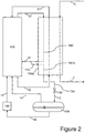
- Figure 2 shows an alternative example where the cooling medium is first cooled down in the cooling circuit pre-cooling pass 190 and is taken out of the heat exchanger 110a as stream 31. A side stream 11a is extracted from stream 31, and is led back to the multistream heat exchanger 110a for further cooling down in the heat exchanger pass 191b.
- Figure 3 shows some more principle alternative examples which can be used individually or simultaneously.
- Figure 3 shows an alternative example where the cooling of said fraction of gaseous cooling medium is performed completely in a separate pre-cooling pass 191c in one or more of said multistream heat exchangers in the heat exchanger system. Alternatively, the cooling can also take place in a separate heat exchanger with the help of the cooling system 100.
- figure 3 shows an embodiment where the cooling medium storage 104 is operated at a higher pressure than the reception pressure for return of cooling medium, in that a pressure control valve controls the pressure in 104 by restricting the flow of gas returning to the cooling circuit.
- Figure 3 also shows that , not according to the invention, return of cooling medium 12 can be done by heating in a separate pass 192 in heat exchanger 110a.
- a corresponding configuration can also be used if a system 110b ( Figure 5 ) consisting of a plurality of heat exchangers in the cooling circuit is used.
- Figure 4 shows two alternative examples that can be used together or individually and together with any of the alternatives described above and in the figures 1-3 .
- the non-condensed cooling medium fraction 14 is not in accordance with the invention, not returned to the cooling system, but is let out of the otherwise closed cooling system as stream 14b, for example, to the atmosphere or for use at other locations in the process plant.
- Figure 4 also shows an example where the system can supply other parts of the processing installation with nitrogen as stream 145, either in the form of a liquid or a gas.
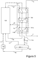
- Figure 5 shows an alternative example where the cooling process uses a plurality of multistream heat exchangers as a system of heat exchangers 110b and where the cooling medium is first cooled in the cooling circuit pre-cooling pass 190 and is taken out from one of the heat exchangers in the system 110b as stream 31.
- a side stream 11a is extracted from stream 31 and led back to the system 110b for further cooling in the heat exchanger pass 191a in the subsequent heat exchanger.
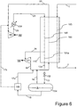
- FIG. 6 shows in detail an example, not in accordance with the invention, but helpful for the understanding of the invention, used in a simple gas expansion circuit, for example, a simple nitrogen expander cooling circuit. It is pointed out that the invention can also be used with other types of gas expansion circuits with different types of cooling medium and with one or more expansion steps.
- the cooling process starts with a gaseous stream of cooling medium 21 at a higher pressure which is pre-cooled in pass 190 in the multistream heat exchanger 110 so that pre-cooled cooling medium 31 can be expanded across the gas expander 121 to generate a cold cooling medium stream 32 at a lower pressure.
- the stream of cooling medium 32 is predominantly in gas phase, but in some designs a small fraction of liquid in equilibrium with the gas at the outlet of the expander/turbine can be allowed.
- Cold cooling medium 32 is returned to the heat exchanger 110 and provides cooling of both warm cooling medium stream 21 in the cooling medium pass 190 and cooling and/or liquefaction of process fluids 1 in one or more cooling medium passes 193 in order to provide the cooled product 7 of the process.
- the cooling medium stream exists as gas at the lower pressure in stream 51.
- This cooling medium stream is recompressed in one or more compression steps 111 with or without inter cooling. Compressed cooling medium 20 is then aftercooled using an external cooling medium or an external cooling circuit 130.
- the disclosed exemplary method starts by extracting a cooling medium stream 191a at the higher pressure after pre-cooling in the heat exchanger pass 190, for further pre-cooling in 191a, until a cold cooling medium stream 12a is formed at the higher pressure.
- Pre-cooled cooling medium 12a can be in the gas or liquid state and is then expanded across a valve 102 to the lower pressure or a pressure between the higher pressure and the lower pressure, but so that the temperature is reduced and a mixture 13 of gas and at least a fraction of liquid are generated.
- the valve 102 will in this context also reduce the amount of cooling medium that is extracted from the cooling circuit.
- the gas and liquid in stream 13 are separated to a liquid fraction which can be stored in a storage tank/pressure tank/separator 104 at a suitable pressure, and a gas stream 14 which is returned at a suitable location in the cooling circuit at the lower pressure, for example, to stream 32 as shown in Figure 5 .
- a gas stream 14 which is returned at a suitable location in the cooling circuit at the lower pressure, for example, to stream 32 as shown in Figure 5 .
- a suitable arrangement 106 is used to return cooling medium from the tank 104 to the cooling circuit via the connection 16, preferably to the part of the cooling circuit that has the lower pressure, for example, as stream 17a to the cold side 32 at the lower pressure, or a stream 17b to the warm side 51 at the lower pressure.
- the arrangement 106 for return and control of cooling medium to the cooling circuit when increased capacity is required can in the simplest example, not in accordance with the invention, be a valve or a pump for dosing of fluid into the cooling circuit.
- a valve With the use of a valve, the flow of liquid back to one of the parts of the cooling circuit, which operate at the lower pressure, can take place by means of gravitational flow as a result of a height difference, or by the storage 104 operating at a higher pressure as described in Figure 3 and the associated description.
- Figure 7 shows an example applied in the simple gas expansion circuit with an alternative method, not in accordance with the invention, for return of cooling medium from the storage 104 to the cooling circuit, with an arrangement 107 being used to supply heat to the cold liquid cooling medium in 104.
- the liquid cooling medium in 104 is evaporated in a controlled way back to the cooling circuit via the gas line 14.
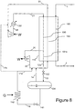
- Figure 8 shows an example used in the simple gas expansion circuit with an alternative method, not in accordance with the invention, for return of cooling medium from the storage 104 to the cooling circuit, in that an arrangement 143 external to the tank 104 is used to supply heat to the cold liquid cooling medium, and in this way the liquid cooling medium from 104 is evaporated in a controlled way back to the cooling circuit via the gas line 17a, 17b or a corresponding connection.
- the arrangement 143 can, for example, be a heat exchanger which uses air from the surroundings as a heat source, or other types of heat exchangers with an available warm medium as an energy source.
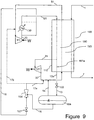
- Figure 9 shows the invention used in the simple gas expansion circuit with an embodiment according to the invention for return of cooling medium from the storage 104 to the cooling circuit, in that an ejector/eductor 108 is being used to obtain a controlled flow of cooling medium back to a suitable location in the cooling circuit.
- the ejector 108 uses a limited amount of motive gas 18 from the high pressure side of the cooling circuit, for example, from outlet 20 of the compressor or from the cooling medium stream 21 downstream the cooler 130.
- the cooling medium can be returned to the part of the cooling circuit that has the lower pressure, for example, as stream 17a to the cold side 32 at the lower pressure or as stream 17b to the warm side 51 at the lower pressure.
- the ejector will give a complete or partial evaporation of the cold liquid 16 so that the returning cooling medium 17a/17b is no longer a pure, cold liquid with subsequent danger of unfavourable liquid/gas flow in the cooling circuit in the period return of cooling medium is carried out.
- Figure 10 shows the invention used in the simple gas expansion circuit with an alternative embodiment according to the invention for return of cooling medium from the storage 104 to the cooling circuit, with an external volume 143 being used, for example, a vessel or a pipe, preferably vertically, where a stream of liquid cooling medium 16 is led in a controlled way to said volume and is mixed with an amount of warmer gas 18 from the high pressure side of the cooling circuit, for example, from the outlet 20 of the compressor or from the cooling medium stream 21 downstream the cooler 130.
- the warmer gas 18 will then supply heat so that the desired amount of cooling medium is evaporated to gas and can be returned to the part of the cooling circuit which has the lowest pressure, for example, as stream 17a to the cold side 32 at the lower pressure or as stream 17b to the warm side 51 at the lower pressure.
- This set up will lead to a complete evaporation of the cold liquid 16 so that the returning cooling medium 17a/17b is no longer a cold liquid with subsequent risk of unfavourable liquid/gas flow in the cooling circuit during the period cooling medium return is carried out.
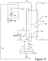
- Figure 11 shows the invention applied in the simple gas expansion circuit with an alternative embodiment according to the invention for return of cooling medium from the storage 104 to the cooling circuit, with an arrangement being used where a warmer cooling medium stream 18 is supplied from a location in the cooling circuit where the pressure is somewhat higher than in the storage 104, to be introduced in 104 via a suitable arrangement, for example, nozzles, so that the heat in the warmer gas contributes to a controlled evaporation of the cold liquid in 104.
- a suitable arrangement for example, nozzles
- a cooling system for example for liquefaction of LNG, is often more comprehensive/involves more details than what is covered in the description above. However, the principles for the embodiment of the invention are the same.
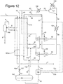
- a cooling system for liquefaction of natural gas to LNG by use of a double gas expansion circuit that uses pure nitrogen as cooling medium is shown in Figure 12 .
- a gas stream 1 comprising natural gas which shall be liquefied is cooled in more than one step in the heat exchanger 110 in that the gas is pre-cooled to an intermediate temperature 4 where heavier hydrocarbons can be separated as liquid in a separator or column 160.
- Pre-cooled gas 6 is then conducted back to the heat exchanger 110 for further cooling, condensing and subcooling, until the liquid exists as LNG in the product stream 7.
- the cooling circuit now comprises a gaseous cooling medium stream 21 at a higher pressure which is divided into two parts 30 and 40 which are pre-cooled to different temperatures in the heat exchanger 110.
- Stream 30 is pre-cooled to a lower temperature than the temperature in 30 and is expanded across gas expander 121 to generate a cold cooling medium stream 32 at a lower pressure.
- the cooling medium stream 32 is predominantly in a gas phase, but in some designs a small liquid fraction in equilibrium with the gas at the outlet of the expander/turbine can be allowed.
- Cold cooling medium 32 is returned to the heat exchanger 110 to contribute with cooling.
- Stream 40 is pre-cooled to a temperature lower than the temperature in 32 and is expanded across a gas expander 122 to generate a cold cooling medium stream 42 at a lower pressure.
- the cooling medium stream 42 is predominantly in a gas phase, but in some designs a small liquid fraction in equilibrium with the gas at the outlet of the expander/turbine can be allowed. Cold cooling medium 42 is returned to the heat exchanger 110 to ensure the cooling in the lowest temperature range. After warming up in 110 the cooling medium streams now exist as the gas streams 33 and 43 at the lower pressure. These gas streams can then be recompressed in one or more compression steps with or without intercooling. It must be pointed out that the splitting of the cooling medium stream must not necessarily take place before the heat exchanger 110, but can also take place as an integrated part of the heat exchanger 110 in that the pass divides the gas stream for outlet of a stream 31 in an intermediate outlet and for further cooling of the remaining gas 41.
- the heating of the cold gas 32 and 42 can occur in such a way that the streams are mixed as an integrated part of the exchanger.
- the method starts in this context by extracting a cooling medium stream 191a at the higher pressure after pre-cooling in the heat exchanger pass 190, for further cooling in 191a until a cold cooling medium stream 12a at the higher pressure exists. It is pointed out that all of the methods for separation of a side stream of cooling medium for further cooling described above and in the figures 1-3 can be used in this set up also.
- Cooled cooling medium 12 is expanded across a valve 102 to the lower pressure, or a pressure between the higher pressure and the lower pressure, but so that the temperature is reduced and a mixture 13 of gas and at least a fraction of liquid is generated.
- the valve 102 controls the amount of cooling medium which is extracted from the cooling circuit.
- the gas and liquid in stream 13 are separated to a liquid fraction which can be stored in a storage tank/ pressure tank/separator 104 at a suitable pressure, and a gas stream 14 at the lower pressure which is returned at a suitable location in the cooling circuit, for example, to stream 32 or 42 via 14b and 14a, respectively.
- a suitable arrangement 106 to return cooling medium 16 from 104 to the cooling circuit is used, according to the invention, to the part of the cooling circuit that has the lower pressure, for example, as stream 17a to the cold side 32 at the lower pressure, or as stream 17c to the cold side 42 at the lower pressure, or as stream 17b to the warm side 51 at the lower pressure.
- all of the alternative methods described above for return of the cooling medium to the cooling circuit can also be used, however, only the methods of the embodiments described in Figs. 9-11 are in accordance with the invention.
- gas stream 14 can be returned to other locations in the cooling circuit than those described through the figures and the examples given above, as long as the pressure is low enough, and the invention is not limited to the examples described here.
- cooling medium 17 can be returned to other locations in the cooling circuit than those described in the figures and in the examples given above as long this location is on the low pressure side of the cooling circuit.
- the cooling medium tank can be set up as a horizontal tank or a vertical tank.
- the cooling medium tank 104 can be a conventional tank or a double walled vacuum-insulated tank which is normally used for storing cryogen/low temperature liquids and liquid gases.
- the cooling medium tank 104 can be placed in the vicinity of the cooling system 100 and the heat exchanger system 110 and can be insulated to minimise evaporation as a consequence of heat transfer from the surroundings.
- the cooling medium tank 104 can be placed together with the heat exchanger system 110 inside a closed and limited volume which is filled with insulation material to limit heat transfer from the surroundings.
- the insulated volume is often shaped as a box and is normally described as a "cold box".
- the insulating material can be conventional insulation or granular insulating material which is filled into the box, such as perlite.
- the cooling medium tank 104 can also be used as cooling medium storage, for example, where the cooling medium is nitrogen, and such that the cooling medium tank can supply other parts of the processing installation with liquid or gaseous nitrogen when required.
Description
- The present invention relates to a method to regulate the cooling capacity of a cooling system based on a gas expansion process as can be seen in the preamble of
patent claim 1.US 3 874 185 A discloses a method of regulating the cooling capacity of a closed gas expansion cooling circuit according to the preamble ofclaim 1. - Cooling processes based on gas expansion as cooling principle are often used where a simple and robust cooling installation is required for cooling a gas or liquid to very low temperatures, such as liquefaction of natural gas to LNG, or in cryogenic separation of air. The gas expansion process is normally based on the classic Brayton/Claude cooling process where a gaseous cooling medium goes through a work cycle based on compression, cooling, expansion and thereafter, heat exchange with the fluid that is to be cooled down. For example, for liquefaction of natural gas one can use a pre-cooled, compressed cooling medium in a gas phase, normally nitrogen or a hydrocarbon gas, or a mixture, which is pre-cooled and expanded across a turbine (for example, a radial turbine/turbo expander) or an expansion valve. The gas expansion leads to the generation of a very cold gas, or a mixture of gas and liquid, which is then used to liquefy natural gas and to pre-cool the compressed cooling gas. The gas expansion processes are relatively simple and therefore well suited for offshore installation. The processes can be based on a single expansion loop, or have two or more expansion steps coupled in parallel or in series, where the different expansion steps operate at different processing conditions (pressure, temperature, amount of flow) to increase the efficiency of the process. However, common for most of the processes is that the cooling medium is predominantly present in gas phase throughout the entire process.
- As the cooling medium in gas expansion processes predominantly is present in gas phase through the entire system, the capacity regulation of these processes will often be challenging. Capacity regulation is relevant when less cooling work is required to carry out a desired cooling and/or liquefaction, for example, when less fluid that shall be cooled or condensed flows through the system, or when the fluid that shall be cooled or liquefied changes composition such that specific cooling work is reduced. Reduced capacity can, to a limited extent, be achieved by reducing the cooling medium compressor duty, for example, by variable inlet guide vanes, or speed control, or gas recycling from the discharge back to the compressor suction. However, by reducing the cooling medium volume flow rate, the expansion turbines will also provide a reduced efficiency and lower power output, or more seriously that problems will arise with control of the expansion turbine, or that the expansion turbines can not be operated over time in such an operating range. Then a situation can arise where the desired low temperature, which is necessary for the process, can not be achieved.
- As a consequence of the equipment related limitations for reduction of cooling capacity in the process, another principle is normally used, in that the content of cooling medium in the closed cooling circuit is reduced (is removed permanently or temporarily from the closed loop). In this way, the operating pressure in the whole cooling circuit will be reduced, both on the high pressure side and the low pressure side. Normally, radial compressors and radial turbines are used in such cooling processes, and since compression or expansion in these machines is volume based the equipment will continue to handle a relatively fixed actual volume per unit time. By reducing the operating pressures, the same actual volume flow will be circulated, but the mass flow will be lower. In this way, a lower cooling duty is achieved with a corresponding reduction of necessary compression work, while the system will operate close to its design points.
- The challenge with the latter method for capacity regulation is loss of cooling gas in case of a temporary reduction of the cooling capacity. In a large installation, one will, for example, have to use a very long time to supply large amounts of cooling medium gas of proper quality, for example, purified nitrogen, after a period with capacity reduction. Hence, it will take long time to re-establish the capacity again. Alternatives with storage or "trapping" of gas between the two pressure levels the process operates between are used, and will constitute a reasonable alternative for small installations. Other solutions comprise storage of cooling medium gas in pressure containers so that large amounts of gas can be injected into the cooling circuit when additional amounts are required.
- The present invention represents a considerable optimisation of the capacity regulation of a gas expansion circuit, and in particular for large installations, such as a cooling installation for production of LNG, in that the cooling process is modified in such a way that the cooling medium gas can simply be cooled down and liquefied within a relatively short time, for intermediate storage in liquid form, and in this way be removed temporarily from the cooling circuit. The cooling circuit will then operate at a lower filling rate with subsequent lower operating pressure and reduced cooling duty. The liquefied gas can at any time be evaporated into the cooling circuit again to quickly increase the duty of the cooling installation. Storage of cooling medium gas in the liquid form at low temperature will require considerably smaller storage volumes than storage of the gas in compressed form. Liquefaction of the cooling medium gas does not require large cooling capacity in the cooling installation, as the liquefaction is carried out over a short period when the duty of the installation is being reduced and there is an excess of cooling capacity in the installation.
- The invention is intended for use in all types of gas expansion circuits where the cooling medium is predominantly in gas phase throughout the entire cooling circuit, such as all types of nitrogen expansion cycles, or gas expansion cycles that use pure methane, natural gas or a mixture of hydrocarbons, and where cooling is obtained by expanding the gaseous cooling medium.
- The abovementioned objects are achieved with a method for controlling the cooling capacity of a cooling system that uses a cooling circuit for gas expansion cooling, as described in the
independent claim 1. - Preferred embodiments of the method are described in the dependent claims 2-10.
- The above mentioned objects are achieved with a use, according to claim 11, of the method according to any of claims 1-10.
- The invention will now be described in more detail with reference to the enclosed figures, in which:
-
Figure 1 shows the main operating principle of an example not in accordance with the invention, which is helpful for understanding the invention. -
Figure 2 shows the main operating principle an alternative example not in accordance with the invention, which is helpful for understanding the invention. -
Figure 3 shows the main operating principle of an alternative example not in accordance with the invention, which is helpful for understanding the invention. -
Figure 4 shows the main operating principle of an alternative example not in accordance with the invention, which is helpful for understanding the invention. -
Figure 5 shows the main operating principle of an alternative example not in accordance with the invention, which is helpful for understanding the invention. -
Figure 6 shows an alternative example not in accordance with the invention, which is helpful for understanding the invention for a simple gas expansion circuit. -
Figure 7 shows an alternative example not in accordance with the invention, which is helpful for understanding the invention for a simple gas expansion circuit. -
Figure 8 shows an alternative example not in accordance with the invention, which is helpful for understanding the invention for a simple gas expansion circuit. -
Figure 9 shows the invention for a simple gas expansion circuit. -
Figure 10 shows the invention for a simple gas expansion circuit with an alternative embodiment. -
Figure 11 shows the invention for a simple gas expansion circuit with an alternative embodiment. -
Figure 12 shows a preferred alternative example not in accordance with the invention, which is helpful for understanding the invention for a two step gas expansion circuit. - With reference to
Figure 1 andFigure 2 , a system for capacity control of the gas expansion circuit will include the following principal components: - 1. Cooling of a fraction of the cooling medium at a higher pressure by means of the
cooling process 100. - 2. Removal of said fraction of cooled
cooling medium 12a for expansion across thepressure reduction device 102 to a lower pressure, so that at least a small fraction of the cooling medium in thecooling medium stream 13 is liquefied at the lower pressure. - 3. A storage/
tank 104 for liquid phase cooling medium. - 4. Separation of
cooling medium stream 13 into a stream of non-condensedcooling medium gas 14 and liquid phase cooling medium, preferably this separation takes place in thecooling medium tank 104. - 5. Return of non-condensed cooling medium and also evaporated cooling medium from the
tank 104 to a suitable location in thecooling system 100. - 6. A
device 106 for return of cooling medium fromstorage tank 104 to thecooling circuit 100 according to need at load increases. - The cooling of cooling medium at the higher pressure will normally be , and is, according to the invention, to a lower temperature than the lowest pre-cooling temperature of the cooling medium in the main cooling circuit, i.e. that the cooling medium stream which shall be extracted for expansion across the
pressure reduction device 102 to a lower pressure must normally be , and is, according to the invention, cooled further compared to the pre-cooling ot other cooling medium streams during normal operating mode for the cooling circuit. However, the pre-cooling temperature for said cooling medium stream which is to be extracted for expansion across thepressure reduction device 102 can not be cooled down to a lower temperature than the lowest operating temperature in the cooling circuit, which normally is a returning cooling medium stream that has been expanded from a higher pressure to a lower pressure, for example as shown asstream 32 inFigure 1 . In those cases the cooling system uses one or more multistream heat exchangers, for example, multistream plate-fin heat exchangers, the cooling can take place partly as a part of one of the main cooling circuit pre-coolpass 190 and partly as adedicated extension 191a of this pre-cooling pass.Figure 1 shows this example as thepre-cooling pass 190 of the cooling circuit is extended directly in the form ofheat exchanger pass 191a, while thecooling medium stream 31 of the main cooling circuit is extracted from theheat exchanger 110a in an intermediate outlet in the heat exchanger.Figure 2 shows an alternative example where the cooling medium is first cooled down in the cooling circuit pre-coolingpass 190 and is taken out of theheat exchanger 110a asstream 31. Aside stream 11a is extracted fromstream 31, and is led back to themultistream heat exchanger 110a for further cooling down in theheat exchanger pass 191b. -
Figure 3 shows some more principle alternative examples which can be used individually or simultaneously.Figure 3 shows an alternative example where the cooling of said fraction of gaseous cooling medium is performed completely in aseparate pre-cooling pass 191c in one or more of said multistream heat exchangers in the heat exchanger system. Alternatively, the cooling can also take place in a separate heat exchanger with the help of thecooling system 100. Furthermore,figure 3 shows an embodiment where the coolingmedium storage 104 is operated at a higher pressure than the reception pressure for return of cooling medium, in that a pressure control valve controls the pressure in 104 by restricting the flow of gas returning to the cooling circuit.Figure 3 also shows that , not according to the invention, return of cooling medium 12 can be done by heating in aseparate pass 192 inheat exchanger 110a. A corresponding configuration can also be used if a system 110b (Figure 5 ) consisting of a plurality of heat exchangers in the cooling circuit is used. -
Figure 4 shows two alternative examples that can be used together or individually and together with any of the alternatives described above and in thefigures 1-3 . InFigure 4 the non-condensedcooling medium fraction 14 is not in accordance with the invention, not returned to the cooling system, but is let out of the otherwise closed cooling system asstream 14b, for example, to the atmosphere or for use at other locations in the process plant.Figure 4 also shows an example where the system can supply other parts of the processing installation with nitrogen asstream 145, either in the form of a liquid or a gas. -
Figure 5 shows an alternative example where the cooling process uses a plurality of multistream heat exchangers as a system of heat exchangers 110b and where the cooling medium is first cooled in the coolingcircuit pre-cooling pass 190 and is taken out from one of the heat exchangers in the system 110b asstream 31. Aside stream 11a is extracted fromstream 31 and led back to the system 110b for further cooling in theheat exchanger pass 191a in the subsequent heat exchanger. -
Figure 6 shows in detail an example, not in accordance with the invention, but helpful for the understanding of the invention, used in a simple gas expansion circuit, for example, a simple nitrogen expander cooling circuit. It is pointed out that the invention can also be used with other types of gas expansion circuits with different types of cooling medium and with one or more expansion steps. The cooling process starts with a gaseous stream of cooling medium 21 at a higher pressure which is pre-cooled inpass 190 in themultistream heat exchanger 110 so thatpre-cooled cooling medium 31 can be expanded across thegas expander 121 to generate a coldcooling medium stream 32 at a lower pressure. The stream of coolingmedium 32 is predominantly in gas phase, but in some designs a small fraction of liquid in equilibrium with the gas at the outlet of the expander/turbine can be allowed.Cold cooling medium 32 is returned to theheat exchanger 110 and provides cooling of both warmcooling medium stream 21 in the coolingmedium pass 190 and cooling and/or liquefaction ofprocess fluids 1 in one or more cooling medium passes 193 in order to provide the cooledproduct 7 of the process. After heating in 110, the cooling medium stream exists as gas at the lower pressure instream 51. This cooling medium stream is recompressed in one ormore compression steps 111 with or without inter cooling.Compressed cooling medium 20 is then aftercooled using an external cooling medium or anexternal cooling circuit 130. In this context the disclosed exemplary method, which is not in accordance with the invention, starts by extracting a coolingmedium stream 191a at the higher pressure after pre-cooling in theheat exchanger pass 190, for further pre-cooling in 191a, until a coldcooling medium stream 12a is formed at the higher pressure.Pre-cooled cooling medium 12a can be in the gas or liquid state and is then expanded across avalve 102 to the lower pressure or a pressure between the higher pressure and the lower pressure, but so that the temperature is reduced and amixture 13 of gas and at least a fraction of liquid are generated. Thevalve 102 will in this context also reduce the amount of cooling medium that is extracted from the cooling circuit. The gas and liquid instream 13 are separated to a liquid fraction which can be stored in a storage tank/pressure tank/separator 104 at a suitable pressure, and agas stream 14 which is returned at a suitable location in the cooling circuit at the lower pressure, for example, to stream 32 as shown inFigure 5 . When the system described above extracts cooling medium throughpass 191a and via thevalve 102 and a liquid is generated in 104, the content of cooling medium in the cooling circuit is correspondingly reduced, and the capacity of the cooling installation is reduced. When the capacity shall be increased again, asuitable arrangement 106 is used to return cooling medium from thetank 104 to the cooling circuit via theconnection 16, preferably to the part of the cooling circuit that has the lower pressure, for example, asstream 17a to thecold side 32 at the lower pressure, or astream 17b to thewarm side 51 at the lower pressure. - The
arrangement 106 for return and control of cooling medium to the cooling circuit when increased capacity is required, can in the simplest example, not in accordance with the invention, be a valve or a pump for dosing of fluid into the cooling circuit. With the use of a valve, the flow of liquid back to one of the parts of the cooling circuit, which operate at the lower pressure, can take place by means of gravitational flow as a result of a height difference, or by thestorage 104 operating at a higher pressure as described inFigure 3 and the associated description. - With the use of a pump in the
arrangement 106, it is also possible to return cooling medium to that part of the cooling circuit which operates at the higher pressure or a part operating at an intermediate pressure. -
Figure 7 shows an example applied in the simple gas expansion circuit with an alternative method, not in accordance with the invention, for return of cooling medium from thestorage 104 to the cooling circuit, with anarrangement 107 being used to supply heat to the cold liquid cooling medium in 104. In this way, the liquid cooling medium in 104 is evaporated in a controlled way back to the cooling circuit via thegas line 14. -
Figure 8 shows an example used in the simple gas expansion circuit with an alternative method, not in accordance with the invention, for return of cooling medium from thestorage 104 to the cooling circuit, in that anarrangement 143 external to thetank 104 is used to supply heat to the cold liquid cooling medium, and in this way the liquid cooling medium from 104 is evaporated in a controlled way back to the cooling circuit via thegas line arrangement 143 can, for example, be a heat exchanger which uses air from the surroundings as a heat source, or other types of heat exchangers with an available warm medium as an energy source. -
Figure 9 shows the invention used in the simple gas expansion circuit with an embodiment according to the invention for return of cooling medium from thestorage 104 to the cooling circuit, in that an ejector/eductor 108 is being used to obtain a controlled flow of cooling medium back to a suitable location in the cooling circuit. Theejector 108 uses a limited amount ofmotive gas 18 from the high pressure side of the cooling circuit, for example, fromoutlet 20 of the compressor or from the coolingmedium stream 21 downstream the cooler 130. The cooling medium can be returned to the part of the cooling circuit that has the lower pressure, for example, asstream 17a to thecold side 32 at the lower pressure or asstream 17b to thewarm side 51 at the lower pressure. The ejector will give a complete or partial evaporation of the cold liquid 16 so that the returning cooling medium 17a/17b is no longer a pure, cold liquid with subsequent danger of unfavourable liquid/gas flow in the cooling circuit in the period return of cooling medium is carried out. -
Figure 10 shows the invention used in the simple gas expansion circuit with an alternative embodiment according to the invention for return of cooling medium from thestorage 104 to the cooling circuit, with anexternal volume 143 being used, for example, a vessel or a pipe, preferably vertically, where a stream ofliquid cooling medium 16 is led in a controlled way to said volume and is mixed with an amount ofwarmer gas 18 from the high pressure side of the cooling circuit, for example, from theoutlet 20 of the compressor or from the coolingmedium stream 21 downstream the cooler 130. Thewarmer gas 18 will then supply heat so that the desired amount of cooling medium is evaporated to gas and can be returned to the part of the cooling circuit which has the lowest pressure, for example, asstream 17a to thecold side 32 at the lower pressure or asstream 17b to thewarm side 51 at the lower pressure. This set up will lead to a complete evaporation of the cold liquid 16 so that the returning cooling medium 17a/17b is no longer a cold liquid with subsequent risk of unfavourable liquid/gas flow in the cooling circuit during the period cooling medium return is carried out. -
Figure 11 shows the invention applied in the simple gas expansion circuit with an alternative embodiment according to the invention for return of cooling medium from thestorage 104 to the cooling circuit, with an arrangement being used where a warmercooling medium stream 18 is supplied from a location in the cooling circuit where the pressure is somewhat higher than in thestorage 104, to be introduced in 104 via a suitable arrangement, for example, nozzles, so that the heat in the warmer gas contributes to a controlled evaporation of the cold liquid in 104. In this way, the liquid cooling medium in 104 is evaporated back into the cooling circuit via thegas line 14 in a controlled manner. - A cooling system, for example for liquefaction of LNG, is often more comprehensive/involves more details than what is covered in the description above. However, the principles for the embodiment of the invention are the same. To illustrate this, a cooling system for liquefaction of natural gas to LNG by use of a double gas expansion circuit that uses pure nitrogen as cooling medium is shown in
Figure 12 . Agas stream 1 comprising natural gas which shall be liquefied is cooled in more than one step in theheat exchanger 110 in that the gas is pre-cooled to anintermediate temperature 4 where heavier hydrocarbons can be separated as liquid in a separator orcolumn 160.Pre-cooled gas 6 is then conducted back to theheat exchanger 110 for further cooling, condensing and subcooling, until the liquid exists as LNG in theproduct stream 7. The cooling circuit now comprises a gaseouscooling medium stream 21 at a higher pressure which is divided into twoparts heat exchanger 110.Stream 30 is pre-cooled to a lower temperature than the temperature in 30 and is expanded acrossgas expander 121 to generate a coldcooling medium stream 32 at a lower pressure. The coolingmedium stream 32 is predominantly in a gas phase, but in some designs a small liquid fraction in equilibrium with the gas at the outlet of the expander/turbine can be allowed.Cold cooling medium 32 is returned to theheat exchanger 110 to contribute with cooling.Stream 40 is pre-cooled to a temperature lower than the temperature in 32 and is expanded across agas expander 122 to generate a coldcooling medium stream 42 at a lower pressure. The coolingmedium stream 42 is predominantly in a gas phase, but in some designs a small liquid fraction in equilibrium with the gas at the outlet of the expander/turbine can be allowed.Cold cooling medium 42 is returned to theheat exchanger 110 to ensure the cooling in the lowest temperature range. After warming up in 110 the cooling medium streams now exist as the gas streams 33 and 43 at the lower pressure. These gas streams can then be recompressed in one or more compression steps with or without intercooling. It must be pointed out that the splitting of the cooling medium stream must not necessarily take place before theheat exchanger 110, but can also take place as an integrated part of theheat exchanger 110 in that the pass divides the gas stream for outlet of astream 31 in an intermediate outlet and for further cooling of the remaininggas 41. In the same way, the heating of thecold gas medium stream 191a at the higher pressure after pre-cooling in theheat exchanger pass 190, for further cooling in 191a until a coldcooling medium stream 12a at the higher pressure exists. It is pointed out that all of the methods for separation of a side stream of cooling medium for further cooling described above and in thefigures 1-3 can be used in this set up also. Cooled cooling medium 12 is expanded across avalve 102 to the lower pressure, or a pressure between the higher pressure and the lower pressure, but so that the temperature is reduced and amixture 13 of gas and at least a fraction of liquid is generated. In this connection, thevalve 102 controls the amount of cooling medium which is extracted from the cooling circuit. The gas and liquid instream 13 are separated to a liquid fraction which can be stored in a storage tank/ pressure tank/separator 104 at a suitable pressure, and agas stream 14 at the lower pressure which is returned at a suitable location in the cooling circuit, for example, to stream 32 or 42 via 14b and 14a, respectively. When the system described above extracts cooling medium throughpass 191a and via thevalve 102 and liquid is generated in 104, the content of cooling medium in the cooling circuit is correspondingly reduced and the capacity of the cooling installation is reduced. When the capacity shall be increased again, asuitable arrangement 106 to return cooling medium 16 from 104 to the cooling circuit is used, according to the invention, to the part of the cooling circuit that has the lower pressure, for example, asstream 17a to thecold side 32 at the lower pressure, or asstream 17c to thecold side 42 at the lower pressure, or asstream 17b to thewarm side 51 at the lower pressure. In principle, all of the alternative methods described above for return of the cooling medium to the cooling circuit can also be used, however, only the methods of the embodiments described inFigs. 9-11 are in accordance with the invention. - It must be pointed out that in all embodiments of the invention the
gas stream 14 can be returned to other locations in the cooling circuit than those described through the figures and the examples given above, as long as the pressure is low enough, and the invention is not limited to the examples described here. - It is pointed out that in all embodiments of the invention the cooling
medium 17 can be returned to other locations in the cooling circuit than those described in the figures and in the examples given above as long this location is on the low pressure side of the cooling circuit. - In all the embodiments of the invention described above and in the figures, the cooling medium tank can be set up as a horizontal tank or a vertical tank. Furthermore, the cooling
medium tank 104 can be a conventional tank or a double walled vacuum-insulated tank which is normally used for storing cryogen/low temperature liquids and liquid gases. - Furthermore, the cooling
medium tank 104 can be placed in the vicinity of thecooling system 100 and theheat exchanger system 110 and can be insulated to minimise evaporation as a consequence of heat transfer from the surroundings. In an alternative embodiment the coolingmedium tank 104 can be placed together with theheat exchanger system 110 inside a closed and limited volume which is filled with insulation material to limit heat transfer from the surroundings. The insulated volume is often shaped as a box and is normally described as a "cold box". The insulating material can be conventional insulation or granular insulating material which is filled into the box, such as perlite. - In an alternative example, not in accordance with the invention, the cooling
medium tank 104 can also be used as cooling medium storage, for example, where the cooling medium is nitrogen, and such that the cooling medium tank can supply other parts of the processing installation with liquid or gaseous nitrogen when required.
Claims (11)
- Method of regulating a cooling capacity of a closed gas expansion cooling circuit (100), with a high pressure and a low pressure side, where a gaseous cooling medium goes through a work cycle based on compression, pre-cooling, expansion and thereafter heat exchange with a fluid that is to be cooled down,
where a reduction in the cooling capacity is achieved by the steps of:- removing a fraction of cooling medium at the high pressure from the cooling circuit and cooling the fraction of cooling medium at the high pressure to a temperature lower than the lowest pre-cooling temperature of the cooling medium in the cooling circuit;- expanding the fraction of the cooling medium across an expansion device (102) to a lower pressure lower than said high pressure so that at least a fraction of the cooling medium separates as a cold liquid;- separating the liquid from non-condensed gas for temporary storage in a storage unit (104) not belonging to the otherwise closed cooling circuit, such that the liquid is not circulating in the cooling circuit;- returning the non-condensed gas and evaporated cooling medium (14) from the storage unit (104) to the cooling circuit (100); andwhere an increase in the cooling capacity is achieved by the steps of- evaporating the stored liquid cooling medium;- returning the evaporated liquid cooling medium to the cooling circuit (100)characterised in that warm gas (18) from the high pressure side of the cooling circuit is used to evaporate the stored liquid cooling medium which is thereafter returned to the low pressure side of the cooling circuit. - Method according to claim 1, characterised in that an external volume (143) is used, for example, a vessel or a pipe, where a stream of liquid cooling medium (16) is led in a controlled way by use of a valve (141) from the storage unit (104) to the external volume (143) and mixed with the warm gas (18) from the high pressure side of the cooling circuit (100).
- Method according to claim 1, characterised in that an ejector/eductor (108) is being used to obtain a controlled flow of cooling medium from the storage unit (104) back to the cooling circuit (100), the ejector/eductor (108) uses the warm gas (18) from the high pressure side of the cooling circuit (100) as motive gas.
- Method according to claim 1, characterised in that the warm gas stream (18) is supplied from the high pressure side of the cooling circuit (100), introduced in the storage unit (104) via a suitable arrangement, so that heat in the warm gas contributes to a controlled evaporation of the cold liquid in the storage unit (104) for return back into the cooling circuit (100) via a gas line (14).
- Method according to any of the preceding claims, characterised in that the warm gas stream (18) from the high pressure side of the cooling circuit is from an outlet (20) of a compressor (111) or from a cooling medium stream (21) downstream of a compressor after-cooler (130) downstream of the compressor.
- Method according to any of the preceding claims 5, characterised in that evaporated liquid cooling medium is returned as stream (17a, 14) to a cold side (32) of the cooling circuit (100) at the low pressure, or a stream (17b) to a warm side (51) of the cooling circuit (100) at the low pressure.
- Method according to any of the preceding claims, characterised in that the fraction of cooling medium is cooled at the high pressure to a temperature such that at least one fraction of said fraction of cooling medium is present as a liquid after the pre-cooling, or that the entire fraction of said cooling medium is present as a liquid after the cooling.
- Method according to any of the preceding claims, characterised in that said expansion device (102) for expansion of cooled cooling medium from the high pressure to the lower pressure is a valve suitable to such expansion.
- Method according to any of the preceding claims, characterised in that said cooling circuit (100) is a gas expansion cooling circuit (100) which uses a cooling medium composed of more than 90% nitrogen, whereby the cooling circuit (100) comprises at least one expansion step where pre-cooled gaseous cooling medium is expanded from the high pressure to the low pressure to generate a cold gaseous cooling medium.
- Method according to any of the preceding claims, characterised in that the storage unit (104) is operated at approximately the same pressure as the low pressure in the cooling circuit (100), in that the storage unit (104) has an open connection (14) without restrictions to the part of the cooling circuit (100) which is operated at the low pressure, or
the storage unit (104) is operated at a pressure between the high pressure and the low pressure of the cooling circuit (100), in that the storage unit (104) has a connection (14) with a restriction, such as a valve, for control of the operating pressure in the storage unit (104). - Use of the method according to any of the preceding claims for production of liquid natural gas (LNG).
Applications Claiming Priority (2)
| Application Number | Priority Date | Filing Date | Title |
|---|---|---|---|
| NO20076291A NO328493B1 (en) | 2007-12-06 | 2007-12-06 | System and method for regulating the cooling process |
| PCT/NO2008/000434 WO2009072900A1 (en) | 2007-12-06 | 2008-12-05 | Method and system for regulation of cooling capacity of a cooling system based on a gas expansion process. |
Publications (3)
| Publication Number | Publication Date |
|---|---|
| EP2229567A1 EP2229567A1 (en) | 2010-09-22 |
| EP2229567A4 EP2229567A4 (en) | 2018-01-24 |
| EP2229567B1 true EP2229567B1 (en) | 2021-06-02 |
Family
ID=40717928
Family Applications (1)
| Application Number | Title | Priority Date | Filing Date |
|---|---|---|---|
| EP08857460.3A Active EP2229567B1 (en) | 2007-12-06 | 2008-12-05 | Method for regulation of cooling capacity of a cooling system based on a gas expansion process. |
Country Status (9)
| Country | Link |
|---|---|
| US (1) | US9528758B2 (en) |
| EP (1) | EP2229567B1 (en) |
| JP (1) | JP5410443B2 (en) |
| KR (1) | KR20100118564A (en) |
| AU (1) | AU2008332005B2 (en) |
| BR (1) | BRPI0820929B1 (en) |
| CA (1) | CA2711372C (en) |
| NO (1) | NO328493B1 (en) |
| WO (1) | WO2009072900A1 (en) |
Families Citing this family (23)
| Publication number | Priority date | Publication date | Assignee | Title |
|---|---|---|---|---|
| US8464551B2 (en) * | 2008-11-18 | 2013-06-18 | Air Products And Chemicals, Inc. | Liquefaction method and system |
| US9291388B2 (en) * | 2009-06-16 | 2016-03-22 | Praxair Technology, Inc. | Method and system for air separation using a supplemental refrigeration cycle |
| JP5465326B2 (en) * | 2009-07-02 | 2014-04-09 | ブルーウォーター・エナジー・サービスィズ・ベー・フェー | Pressure control after gas liquefaction system shutdown |
| US10132561B2 (en) * | 2009-08-13 | 2018-11-20 | Air Products And Chemicals, Inc. | Refrigerant composition control |
| DE102010044869A1 (en) * | 2010-09-09 | 2012-03-15 | Linde Aktiengesellschaft | Liquefied Natural gas |
| NO2769159T3 (en) * | 2011-10-21 | 2018-06-09 | ||
| US9429335B2 (en) * | 2012-01-11 | 2016-08-30 | Hewlett Packard Enterprise Development Lp | Adiabatic cooling unit |
| JP5890748B2 (en) * | 2012-05-22 | 2016-03-22 | 川崎重工業株式会社 | Liquid hydrogen production equipment |
| GB2503731A (en) * | 2012-07-06 | 2014-01-08 | Highview Entpr Ltd | Cryogenic energy storage and liquefaction process |
| SG11201503053SA (en) * | 2012-11-16 | 2015-06-29 | Exxonmobil Upstream Res Co | Liquefaction of natural gas |
| US11408673B2 (en) | 2013-03-15 | 2022-08-09 | Chart Energy & Chemicals, Inc. | Mixed refrigerant system and method |
| US11428463B2 (en) | 2013-03-15 | 2022-08-30 | Chart Energy & Chemicals, Inc. | Mixed refrigerant system and method |
| AU2014232154B2 (en) | 2013-03-15 | 2019-05-02 | Chart Energy & Chemicals, Inc. | Mixed refrigerant system and method |
| US9759480B2 (en) * | 2014-10-10 | 2017-09-12 | Air Products And Chemicals, Inc. | Refrigerant recovery in natural gas liquefaction processes |
| DE102016000394A1 (en) * | 2016-01-14 | 2017-07-20 | Linde Aktiengesellschaft | Method for cooling a medium |
| GB201601878D0 (en) | 2016-02-02 | 2016-03-16 | Highview Entpr Ltd | Improvements in power recovery |
| KR101792708B1 (en) * | 2016-06-22 | 2017-11-02 | 삼성중공업(주) | Apparatus of fluid cooling |
| US10619917B2 (en) | 2017-09-13 | 2020-04-14 | Air Products And Chemicals, Inc. | Multi-product liquefaction method and system |
| CN108061405A (en) * | 2018-01-23 | 2018-05-22 | 郑州云宇新能源技术有限公司 | Self cooled high-performance CO2Trans-critical cycle heat pump circulating system |
| GB2581135A (en) * | 2019-01-30 | 2020-08-12 | Linde Ag | Cooling method for liquefying a feed gas |
| US20220404094A1 (en) * | 2019-12-19 | 2022-12-22 | Praxair Technology, Inc. | System and m ethod for supplying cryogenic refrigeration |
| US11740014B2 (en) | 2020-02-27 | 2023-08-29 | Praxair Technology, Inc. | System and method for natural gas and nitrogen liquefaction with independent nitrogen recycle loops |
| DE102020205183A1 (en) * | 2020-04-23 | 2021-10-28 | Karlsruher Institut für Technologie | Device and method for generating cryogenic temperatures and their use |
Citations (1)
| Publication number | Priority date | Publication date | Assignee | Title |
|---|---|---|---|---|
| JP2004309029A (en) * | 2003-04-08 | 2004-11-04 | Matsushita Electric Ind Co Ltd | Refrigerating cycle device |
Family Cites Families (16)
| Publication number | Priority date | Publication date | Assignee | Title |
|---|---|---|---|---|
| US3792590A (en) * | 1970-12-21 | 1974-02-19 | Airco Inc | Liquefaction of natural gas |
| NO133287C (en) * | 1972-12-18 | 1976-04-07 | Linde Ag | |
| GB2069119B (en) * | 1980-02-13 | 1983-09-21 | Petrocarbon Dev Ltd | Refrigeration process |
| JPS62786A (en) * | 1985-06-25 | 1987-01-06 | 株式会社神戸製鋼所 | Precooling method of cryogenic generator |
| US4843829A (en) * | 1988-11-03 | 1989-07-04 | Air Products And Chemicals, Inc. | Reliquefaction of boil-off from liquefied natural gas |
| US5271231A (en) * | 1992-08-10 | 1993-12-21 | L'air Liquide, Societe Anonyme Pour L'etude Et L'exploitation Des Procedes Georges Claude | Method and apparatus for gas liquefaction with plural work expansion of feed as refrigerant and air separation cycle embodying the same |
| DE4440405C1 (en) * | 1994-11-11 | 1996-05-23 | Linde Ag | Method for temporarily storing a refrigerant |
| JPH10253203A (en) * | 1997-03-13 | 1998-09-25 | Mitsubishi Electric Corp | Refrigerant recovering method |
| JPH1114170A (en) * | 1997-06-23 | 1999-01-22 | Sanyo Electric Co Ltd | Heat pump |
| US6347531B1 (en) * | 1999-10-12 | 2002-02-19 | Air Products And Chemicals, Inc. | Single mixed refrigerant gas liquefaction process |
| US6347532B1 (en) * | 1999-10-12 | 2002-02-19 | Air Products And Chemicals, Inc. | Gas liquefaction process with partial condensation of mixed refrigerant at intermediate temperatures |
| GB0006265D0 (en) * | 2000-03-15 | 2000-05-03 | Statoil | Natural gas liquefaction process |
| CR7129A (en) * | 2003-10-29 | 2003-11-17 | Carlos Eduardo Rold N Villalobos | METHOD AND APPARATUS FOR STORAGE GASES AT LOW TEMPERATURE USING A REFRIGERATION RECOVERY SYSTEM |
| US7096679B2 (en) * | 2003-12-23 | 2006-08-29 | Tecumseh Products Company | Transcritical vapor compression system and method of operating including refrigerant storage tank and non-variable expansion device |
| JP4670329B2 (en) * | 2004-11-29 | 2011-04-13 | 三菱電機株式会社 | Refrigeration air conditioner, operation control method of refrigeration air conditioner, refrigerant amount control method of refrigeration air conditioner |
| EP1790926A1 (en) * | 2005-11-24 | 2007-05-30 | Shell Internationale Researchmaatschappij B.V. | Method and apparatus for cooling a stream, in particular a hydrocarbon stream such as natural gas |
-
2007
- 2007-12-06 NO NO20076291A patent/NO328493B1/en unknown
-
2008
- 2008-12-05 WO PCT/NO2008/000434 patent/WO2009072900A1/en active Application Filing
- 2008-12-05 KR KR1020107014949A patent/KR20100118564A/en not_active Application Discontinuation
- 2008-12-05 US US12/734,937 patent/US9528758B2/en active Active
- 2008-12-05 AU AU2008332005A patent/AU2008332005B2/en active Active
- 2008-12-05 CA CA2711372A patent/CA2711372C/en active Active
- 2008-12-05 BR BRPI0820929-4A patent/BRPI0820929B1/en active IP Right Grant
- 2008-12-05 EP EP08857460.3A patent/EP2229567B1/en active Active
- 2008-12-05 JP JP2010536872A patent/JP5410443B2/en active Active
Patent Citations (1)
| Publication number | Priority date | Publication date | Assignee | Title |
|---|---|---|---|---|
| JP2004309029A (en) * | 2003-04-08 | 2004-11-04 | Matsushita Electric Ind Co Ltd | Refrigerating cycle device |
Also Published As
| Publication number | Publication date |
|---|---|
| JP5410443B2 (en) | 2014-02-05 |
| EP2229567A4 (en) | 2018-01-24 |
| NO328493B1 (en) | 2010-03-01 |
| US9528758B2 (en) | 2016-12-27 |
| KR20100118564A (en) | 2010-11-05 |
| NO20076291L (en) | 2009-06-08 |
| WO2009072900A1 (en) | 2009-06-11 |
| CA2711372C (en) | 2017-07-25 |
| BRPI0820929A2 (en) | 2015-06-23 |
| AU2008332005B2 (en) | 2014-01-23 |
| JP2011506894A (en) | 2011-03-03 |
| US20100236286A1 (en) | 2010-09-23 |
| EP2229567A1 (en) | 2010-09-22 |
| BRPI0820929B1 (en) | 2020-09-15 |
| AU2008332005A1 (en) | 2009-06-11 |
| CA2711372A1 (en) | 2009-06-11 |
Similar Documents
| Publication | Publication Date | Title |
|---|---|---|
| EP2229567B1 (en) | Method for regulation of cooling capacity of a cooling system based on a gas expansion process. | |
| US6253574B1 (en) | Method for liquefying a stream rich in hydrocarbons | |
| CA3029950C (en) | System and method for liquefaction of natural gas | |
| RU2141611C1 (en) | Liquefaction method | |
| US8650906B2 (en) | System and method for recovering and liquefying boil-off gas | |
| CN104520660B (en) | System and method for natural gas liquefaction | |
| KR20070084510A (en) | Lng system employing stacked vertical heat exchangers to provide liquid reflux stream | |
| RU2716099C1 (en) | Modular device for separation of spg and heat exchanger of flash gas | |
| KR20070084502A (en) | Vertical heat exchanger configuration for lng facility | |
| US20180313604A1 (en) | Hydrogen-neon mixture refrigeration cycle for large-scale hydrogen cooling and liquefaction | |
| AU2023237164A1 (en) | Liquefaction system | |
| US8991208B2 (en) | Liquefaction process producing subcooled LNG |
Legal Events
| Date | Code | Title | Description |
|---|---|---|---|
| PUAI | Public reference made under article 153(3) epc to a published international application that has entered the european phase |
Free format text: ORIGINAL CODE: 0009012 |
|
| 17P | Request for examination filed |
Effective date: 20100706 |
|
| AK | Designated contracting states |
Kind code of ref document: A1 Designated state(s): AT BE BG CH CY CZ DE DK EE ES FI FR GB GR HR HU IE IS IT LI LT LU LV MC MT NL NO PL PT RO SE SI SK TR |
|
| AX | Request for extension of the european patent |
Extension state: AL BA MK RS |
|
| DAX | Request for extension of the european patent (deleted) | ||
| RAP1 | Party data changed (applicant data changed or rights of an application transferred) |
Owner name: ARAGON AS |
|
| RIC1 | Information provided on ipc code assigned before grant |
Ipc: F25J 1/02 20060101AFI20170913BHEP Ipc: F25J 1/00 20060101ALI20170913BHEP Ipc: F25B 9/02 20060101ALI20170913BHEP |
|
| RA4 | Supplementary search report drawn up and despatched (corrected) |
Effective date: 20171221 |
|
| RIC1 | Information provided on ipc code assigned before grant |
Ipc: F25J 1/02 20060101AFI20171215BHEP Ipc: F25J 1/00 20060101ALI20171215BHEP Ipc: F25B 9/02 20060101ALI20171215BHEP |
|
| STAA | Information on the status of an ep patent application or granted ep patent |
Free format text: STATUS: EXAMINATION IS IN PROGRESS |
|
| 17Q | First examination report despatched |
Effective date: 20200506 |
|
| GRAP | Despatch of communication of intention to grant a patent |
Free format text: ORIGINAL CODE: EPIDOSNIGR1 |
|
| STAA | Information on the status of an ep patent application or granted ep patent |
Free format text: STATUS: GRANT OF PATENT IS INTENDED |
|
| INTG | Intention to grant announced |
Effective date: 20210113 |
|
| RAP1 | Party data changed (applicant data changed or rights of an application transferred) |
Owner name: ARAGON AS |
|
| GRAS | Grant fee paid |
Free format text: ORIGINAL CODE: EPIDOSNIGR3 |
|
| GRAA | (expected) grant |
Free format text: ORIGINAL CODE: 0009210 |
|
| STAA | Information on the status of an ep patent application or granted ep patent |
Free format text: STATUS: THE PATENT HAS BEEN GRANTED |
|
| REG | Reference to a national code |
Ref country code: CH Ref legal event code: EP |
|
| AK | Designated contracting states |
Kind code of ref document: B1 Designated state(s): AT BE BG CH CY CZ DE DK EE ES FI FR GB GR HR HU IE IS IT LI LT LU LV MC MT NL NO PL PT RO SE SI SK TR |
|
| REG | Reference to a national code |
Ref country code: GB Ref legal event code: FG4D |
|
| REG | Reference to a national code |
Ref country code: AT Ref legal event code: REF Ref document number: 1398842 Country of ref document: AT Kind code of ref document: T Effective date: 20210615 |
|
| REG | Reference to a national code |
Ref country code: IE Ref legal event code: FG4D |
|
| REG | Reference to a national code |
Ref country code: DE Ref legal event code: R096 Ref document number: 602008064012 Country of ref document: DE |
|
| REG | Reference to a national code |
Ref country code: NL Ref legal event code: FP |
|
| REG | Reference to a national code |
Ref country code: LT Ref legal event code: MG9D |
|
| PG25 | Lapsed in a contracting state [announced via postgrant information from national office to epo] |
Ref country code: BG Free format text: LAPSE BECAUSE OF FAILURE TO SUBMIT A TRANSLATION OF THE DESCRIPTION OR TO PAY THE FEE WITHIN THE PRESCRIBED TIME-LIMIT Effective date: 20210902 Ref country code: HR Free format text: LAPSE BECAUSE OF FAILURE TO SUBMIT A TRANSLATION OF THE DESCRIPTION OR TO PAY THE FEE WITHIN THE PRESCRIBED TIME-LIMIT Effective date: 20210602 Ref country code: LT Free format text: LAPSE BECAUSE OF FAILURE TO SUBMIT A TRANSLATION OF THE DESCRIPTION OR TO PAY THE FEE WITHIN THE PRESCRIBED TIME-LIMIT Effective date: 20210602 Ref country code: FI Free format text: LAPSE BECAUSE OF FAILURE TO SUBMIT A TRANSLATION OF THE DESCRIPTION OR TO PAY THE FEE WITHIN THE PRESCRIBED TIME-LIMIT Effective date: 20210602 |
|
| REG | Reference to a national code |
Ref country code: AT Ref legal event code: MK05 Ref document number: 1398842 Country of ref document: AT Kind code of ref document: T Effective date: 20210602 |
|
| PG25 | Lapsed in a contracting state [announced via postgrant information from national office to epo] |
Ref country code: LV Free format text: LAPSE BECAUSE OF FAILURE TO SUBMIT A TRANSLATION OF THE DESCRIPTION OR TO PAY THE FEE WITHIN THE PRESCRIBED TIME-LIMIT Effective date: 20210602 Ref country code: GR Free format text: LAPSE BECAUSE OF FAILURE TO SUBMIT A TRANSLATION OF THE DESCRIPTION OR TO PAY THE FEE WITHIN THE PRESCRIBED TIME-LIMIT Effective date: 20210903 Ref country code: SE Free format text: LAPSE BECAUSE OF FAILURE TO SUBMIT A TRANSLATION OF THE DESCRIPTION OR TO PAY THE FEE WITHIN THE PRESCRIBED TIME-LIMIT Effective date: 20210602 Ref country code: PL Free format text: LAPSE BECAUSE OF FAILURE TO SUBMIT A TRANSLATION OF THE DESCRIPTION OR TO PAY THE FEE WITHIN THE PRESCRIBED TIME-LIMIT Effective date: 20210602 Ref country code: NO Free format text: LAPSE BECAUSE OF FAILURE TO SUBMIT A TRANSLATION OF THE DESCRIPTION OR TO PAY THE FEE WITHIN THE PRESCRIBED TIME-LIMIT Effective date: 20210902 |
|
| PG25 | Lapsed in a contracting state [announced via postgrant information from national office to epo] |
Ref country code: AT Free format text: LAPSE BECAUSE OF FAILURE TO SUBMIT A TRANSLATION OF THE DESCRIPTION OR TO PAY THE FEE WITHIN THE PRESCRIBED TIME-LIMIT Effective date: 20210602 Ref country code: PT Free format text: LAPSE BECAUSE OF FAILURE TO SUBMIT A TRANSLATION OF THE DESCRIPTION OR TO PAY THE FEE WITHIN THE PRESCRIBED TIME-LIMIT Effective date: 20211004 Ref country code: RO Free format text: LAPSE BECAUSE OF FAILURE TO SUBMIT A TRANSLATION OF THE DESCRIPTION OR TO PAY THE FEE WITHIN THE PRESCRIBED TIME-LIMIT Effective date: 20210602 Ref country code: ES Free format text: LAPSE BECAUSE OF FAILURE TO SUBMIT A TRANSLATION OF THE DESCRIPTION OR TO PAY THE FEE WITHIN THE PRESCRIBED TIME-LIMIT Effective date: 20210602 Ref country code: CZ Free format text: LAPSE BECAUSE OF FAILURE TO SUBMIT A TRANSLATION OF THE DESCRIPTION OR TO PAY THE FEE WITHIN THE PRESCRIBED TIME-LIMIT Effective date: 20210602 Ref country code: EE Free format text: LAPSE BECAUSE OF FAILURE TO SUBMIT A TRANSLATION OF THE DESCRIPTION OR TO PAY THE FEE WITHIN THE PRESCRIBED TIME-LIMIT Effective date: 20210602 Ref country code: SK Free format text: LAPSE BECAUSE OF FAILURE TO SUBMIT A TRANSLATION OF THE DESCRIPTION OR TO PAY THE FEE WITHIN THE PRESCRIBED TIME-LIMIT Effective date: 20210602 |
|
| REG | Reference to a national code |
Ref country code: DE Ref legal event code: R097 Ref document number: 602008064012 Country of ref document: DE |
|
| PLBE | No opposition filed within time limit |
Free format text: ORIGINAL CODE: 0009261 |
|
| STAA | Information on the status of an ep patent application or granted ep patent |
Free format text: STATUS: NO OPPOSITION FILED WITHIN TIME LIMIT |
|
| PG25 | Lapsed in a contracting state [announced via postgrant information from national office to epo] |
Ref country code: DK Free format text: LAPSE BECAUSE OF FAILURE TO SUBMIT A TRANSLATION OF THE DESCRIPTION OR TO PAY THE FEE WITHIN THE PRESCRIBED TIME-LIMIT Effective date: 20210602 |
|
| 26N | No opposition filed |
Effective date: 20220303 |
|
| PG25 | Lapsed in a contracting state [announced via postgrant information from national office to epo] |
Ref country code: MC Free format text: LAPSE BECAUSE OF FAILURE TO SUBMIT A TRANSLATION OF THE DESCRIPTION OR TO PAY THE FEE WITHIN THE PRESCRIBED TIME-LIMIT Effective date: 20210602 Ref country code: IT Free format text: LAPSE BECAUSE OF FAILURE TO SUBMIT A TRANSLATION OF THE DESCRIPTION OR TO PAY THE FEE WITHIN THE PRESCRIBED TIME-LIMIT Effective date: 20210602 |
|
| REG | Reference to a national code |
Ref country code: CH Ref legal event code: PL |
|
| REG | Reference to a national code |
Ref country code: BE Ref legal event code: MM Effective date: 20211231 |
|
| PG25 | Lapsed in a contracting state [announced via postgrant information from national office to epo] |
Ref country code: LU Free format text: LAPSE BECAUSE OF NON-PAYMENT OF DUE FEES Effective date: 20211205 Ref country code: IE Free format text: LAPSE BECAUSE OF NON-PAYMENT OF DUE FEES Effective date: 20211205 |
|
| PG25 | Lapsed in a contracting state [announced via postgrant information from national office to epo] |
Ref country code: BE Free format text: LAPSE BECAUSE OF NON-PAYMENT OF DUE FEES Effective date: 20211231 |
|
| PG25 | Lapsed in a contracting state [announced via postgrant information from national office to epo] |
Ref country code: LI Free format text: LAPSE BECAUSE OF NON-PAYMENT OF DUE FEES Effective date: 20211231 Ref country code: CH Free format text: LAPSE BECAUSE OF NON-PAYMENT OF DUE FEES Effective date: 20211231 |
|
| PG25 | Lapsed in a contracting state [announced via postgrant information from national office to epo] |
Ref country code: HU Free format text: LAPSE BECAUSE OF FAILURE TO SUBMIT A TRANSLATION OF THE DESCRIPTION OR TO PAY THE FEE WITHIN THE PRESCRIBED TIME-LIMIT; INVALID AB INITIO Effective date: 20081205 Ref country code: CY Free format text: LAPSE BECAUSE OF FAILURE TO SUBMIT A TRANSLATION OF THE DESCRIPTION OR TO PAY THE FEE WITHIN THE PRESCRIBED TIME-LIMIT Effective date: 20210602 |
|
| P01 | Opt-out of the competence of the unified patent court (upc) registered |
Effective date: 20230329 |
|
| PGFP | Annual fee paid to national office [announced via postgrant information from national office to epo] |
Ref country code: NL Payment date: 20231121 Year of fee payment: 16 |
|
| PGFP | Annual fee paid to national office [announced via postgrant information from national office to epo] |
Ref country code: GB Payment date: 20231121 Year of fee payment: 16 |
|
| PGFP | Annual fee paid to national office [announced via postgrant information from national office to epo] |
Ref country code: FR Payment date: 20231122 Year of fee payment: 16 Ref country code: DE Payment date: 20231121 Year of fee payment: 16 |