EP2685093B1 - Windturbinenstabilisierung - Google Patents
Windturbinenstabilisierung Download PDFInfo
- Publication number
- EP2685093B1 EP2685093B1 EP12382274.4A EP12382274A EP2685093B1 EP 2685093 B1 EP2685093 B1 EP 2685093B1 EP 12382274 A EP12382274 A EP 12382274A EP 2685093 B1 EP2685093 B1 EP 2685093B1
- Authority
- EP
- European Patent Office
- Prior art keywords
- gyroscope
- tower
- wind turbine
- axis
- pitch
- Prior art date
- Legal status (The legal status is an assumption and is not a legal conclusion. Google has not performed a legal analysis and makes no representation as to the accuracy of the status listed.)
- Not-in-force
Links
- 230000006641 stabilisation Effects 0.000 title description 3
- 238000011105 stabilization Methods 0.000 title description 3
- 230000033001 locomotion Effects 0.000 claims description 90
- 238000009987 spinning Methods 0.000 claims description 32
- 238000000034 method Methods 0.000 claims description 26
- 230000000087 stabilizing effect Effects 0.000 claims description 21
- 230000007613 environmental effect Effects 0.000 claims description 11
- 238000013016 damping Methods 0.000 description 16
- 238000006243 chemical reaction Methods 0.000 description 10
- 230000000368 destabilizing effect Effects 0.000 description 7
- 230000000694 effects Effects 0.000 description 6
- 230000010355 oscillation Effects 0.000 description 6
- 230000009471 action Effects 0.000 description 5
- 230000008901 benefit Effects 0.000 description 3
- 238000005096 rolling process Methods 0.000 description 3
- 238000000354 decomposition reaction Methods 0.000 description 2
- 230000005484 gravity Effects 0.000 description 2
- 230000008859 change Effects 0.000 description 1
- 230000001687 destabilization Effects 0.000 description 1
- 238000006073 displacement reaction Methods 0.000 description 1
- 230000005284 excitation Effects 0.000 description 1
- 238000001914 filtration Methods 0.000 description 1
- 230000003993 interaction Effects 0.000 description 1
- 238000012986 modification Methods 0.000 description 1
- 230000004048 modification Effects 0.000 description 1
- 230000001105 regulatory effect Effects 0.000 description 1
- 230000000284 resting effect Effects 0.000 description 1
- 230000007704 transition Effects 0.000 description 1
Images


Classifications
-
- F—MECHANICAL ENGINEERING; LIGHTING; HEATING; WEAPONS; BLASTING
- F03—MACHINES OR ENGINES FOR LIQUIDS; WIND, SPRING, OR WEIGHT MOTORS; PRODUCING MECHANICAL POWER OR A REACTIVE PROPULSIVE THRUST, NOT OTHERWISE PROVIDED FOR
- F03D—WIND MOTORS
- F03D7/00—Controlling wind motors
- F03D7/06—Controlling wind motors the wind motors having rotation axis substantially perpendicular to the air flow entering the rotor
-
- B—PERFORMING OPERATIONS; TRANSPORTING
- B63—SHIPS OR OTHER WATERBORNE VESSELS; RELATED EQUIPMENT
- B63B—SHIPS OR OTHER WATERBORNE VESSELS; EQUIPMENT FOR SHIPPING
- B63B21/00—Tying-up; Shifting, towing, or pushing equipment; Anchoring
- B63B21/50—Anchoring arrangements or methods for special vessels, e.g. for floating drilling platforms or dredgers
- B63B21/502—Anchoring arrangements or methods for special vessels, e.g. for floating drilling platforms or dredgers by means of tension legs
-
- F—MECHANICAL ENGINEERING; LIGHTING; HEATING; WEAPONS; BLASTING
- F03—MACHINES OR ENGINES FOR LIQUIDS; WIND, SPRING, OR WEIGHT MOTORS; PRODUCING MECHANICAL POWER OR A REACTIVE PROPULSIVE THRUST, NOT OTHERWISE PROVIDED FOR
- F03D—WIND MOTORS
- F03D13/00—Assembly, mounting or commissioning of wind motors; Arrangements specially adapted for transporting wind motor components
- F03D13/20—Arrangements for mounting or supporting wind motors; Masts or towers for wind motors
- F03D13/22—Foundations specially adapted for wind motors
-
- F—MECHANICAL ENGINEERING; LIGHTING; HEATING; WEAPONS; BLASTING
- F03—MACHINES OR ENGINES FOR LIQUIDS; WIND, SPRING, OR WEIGHT MOTORS; PRODUCING MECHANICAL POWER OR A REACTIVE PROPULSIVE THRUST, NOT OTHERWISE PROVIDED FOR
- F03D—WIND MOTORS
- F03D13/00—Assembly, mounting or commissioning of wind motors; Arrangements specially adapted for transporting wind motor components
- F03D13/20—Arrangements for mounting or supporting wind motors; Masts or towers for wind motors
- F03D13/25—Arrangements for mounting or supporting wind motors; Masts or towers for wind motors specially adapted for offshore installation
-
- F—MECHANICAL ENGINEERING; LIGHTING; HEATING; WEAPONS; BLASTING
- F03—MACHINES OR ENGINES FOR LIQUIDS; WIND, SPRING, OR WEIGHT MOTORS; PRODUCING MECHANICAL POWER OR A REACTIVE PROPULSIVE THRUST, NOT OTHERWISE PROVIDED FOR
- F03D—WIND MOTORS
- F03D7/00—Controlling wind motors
- F03D7/02—Controlling wind motors the wind motors having rotation axis substantially parallel to the air flow entering the rotor
- F03D7/0296—Controlling wind motors the wind motors having rotation axis substantially parallel to the air flow entering the rotor to prevent, counteract or reduce noise emissions
-
- F—MECHANICAL ENGINEERING; LIGHTING; HEATING; WEAPONS; BLASTING
- F03—MACHINES OR ENGINES FOR LIQUIDS; WIND, SPRING, OR WEIGHT MOTORS; PRODUCING MECHANICAL POWER OR A REACTIVE PROPULSIVE THRUST, NOT OTHERWISE PROVIDED FOR
- F03D—WIND MOTORS
- F03D80/00—Details, components or accessories not provided for in groups F03D1/00 - F03D17/00
- F03D80/80—Arrangement of components within nacelles or towers
- F03D80/88—Arrangement of components within nacelles or towers of mechanical components
-
- F—MECHANICAL ENGINEERING; LIGHTING; HEATING; WEAPONS; BLASTING
- F03—MACHINES OR ENGINES FOR LIQUIDS; WIND, SPRING, OR WEIGHT MOTORS; PRODUCING MECHANICAL POWER OR A REACTIVE PROPULSIVE THRUST, NOT OTHERWISE PROVIDED FOR
- F03D—WIND MOTORS
- F03D9/00—Adaptations of wind motors for special use; Combinations of wind motors with apparatus driven thereby; Wind motors specially adapted for installation in particular locations
- F03D9/10—Combinations of wind motors with apparatus storing energy
- F03D9/12—Combinations of wind motors with apparatus storing energy storing kinetic energy, e.g. using flywheels
-
- G—PHYSICS
- G01—MEASURING; TESTING
- G01C—MEASURING DISTANCES, LEVELS OR BEARINGS; SURVEYING; NAVIGATION; GYROSCOPIC INSTRUMENTS; PHOTOGRAMMETRY OR VIDEOGRAMMETRY
- G01C19/00—Gyroscopes; Turn-sensitive devices using vibrating masses; Turn-sensitive devices without moving masses; Measuring angular rate using gyroscopic effects
- G01C19/02—Rotary gyroscopes
-
- B—PERFORMING OPERATIONS; TRANSPORTING
- B63—SHIPS OR OTHER WATERBORNE VESSELS; RELATED EQUIPMENT
- B63B—SHIPS OR OTHER WATERBORNE VESSELS; EQUIPMENT FOR SHIPPING
- B63B21/00—Tying-up; Shifting, towing, or pushing equipment; Anchoring
- B63B21/50—Anchoring arrangements or methods for special vessels, e.g. for floating drilling platforms or dredgers
- B63B2021/505—Methods for installation or mooring of floating offshore platforms on site
-
- B—PERFORMING OPERATIONS; TRANSPORTING
- B63—SHIPS OR OTHER WATERBORNE VESSELS; RELATED EQUIPMENT
- B63B—SHIPS OR OTHER WATERBORNE VESSELS; EQUIPMENT FOR SHIPPING
- B63B35/00—Vessels or similar floating structures specially adapted for specific purposes and not otherwise provided for
- B63B35/44—Floating buildings, stores, drilling platforms, or workshops, e.g. carrying water-oil separating devices
- B63B2035/4433—Floating structures carrying electric power plants
- B63B2035/446—Floating structures carrying electric power plants for converting wind energy into electric energy
-
- B—PERFORMING OPERATIONS; TRANSPORTING
- B63—SHIPS OR OTHER WATERBORNE VESSELS; RELATED EQUIPMENT
- B63B—SHIPS OR OTHER WATERBORNE VESSELS; EQUIPMENT FOR SHIPPING
- B63B39/00—Equipment to decrease pitch, roll, or like unwanted vessel movements; Apparatus for indicating vessel attitude
- B63B39/04—Equipment to decrease pitch, roll, or like unwanted vessel movements; Apparatus for indicating vessel attitude to decrease vessel movements by using gyroscopes directly
-
- F—MECHANICAL ENGINEERING; LIGHTING; HEATING; WEAPONS; BLASTING
- F05—INDEXING SCHEMES RELATING TO ENGINES OR PUMPS IN VARIOUS SUBCLASSES OF CLASSES F01-F04
- F05B—INDEXING SCHEME RELATING TO WIND, SPRING, WEIGHT, INERTIA OR LIKE MOTORS, TO MACHINES OR ENGINES FOR LIQUIDS COVERED BY SUBCLASSES F03B, F03D AND F03G
- F05B2240/00—Components
- F05B2240/90—Mounting on supporting structures or systems
- F05B2240/93—Mounting on supporting structures or systems on a structure floating on a liquid surface
-
- F—MECHANICAL ENGINEERING; LIGHTING; HEATING; WEAPONS; BLASTING
- F05—INDEXING SCHEMES RELATING TO ENGINES OR PUMPS IN VARIOUS SUBCLASSES OF CLASSES F01-F04
- F05B—INDEXING SCHEME RELATING TO WIND, SPRING, WEIGHT, INERTIA OR LIKE MOTORS, TO MACHINES OR ENGINES FOR LIQUIDS COVERED BY SUBCLASSES F03B, F03D AND F03G
- F05B2240/00—Components
- F05B2240/90—Mounting on supporting structures or systems
- F05B2240/95—Mounting on supporting structures or systems offshore
-
- F—MECHANICAL ENGINEERING; LIGHTING; HEATING; WEAPONS; BLASTING
- F05—INDEXING SCHEMES RELATING TO ENGINES OR PUMPS IN VARIOUS SUBCLASSES OF CLASSES F01-F04
- F05B—INDEXING SCHEME RELATING TO WIND, SPRING, WEIGHT, INERTIA OR LIKE MOTORS, TO MACHINES OR ENGINES FOR LIQUIDS COVERED BY SUBCLASSES F03B, F03D AND F03G
- F05B2260/00—Function
- F05B2260/96—Preventing, counteracting or reducing vibration or noise
- F05B2260/964—Preventing, counteracting or reducing vibration or noise by damping means
-
- F—MECHANICAL ENGINEERING; LIGHTING; HEATING; WEAPONS; BLASTING
- F05—INDEXING SCHEMES RELATING TO ENGINES OR PUMPS IN VARIOUS SUBCLASSES OF CLASSES F01-F04
- F05B—INDEXING SCHEME RELATING TO WIND, SPRING, WEIGHT, INERTIA OR LIKE MOTORS, TO MACHINES OR ENGINES FOR LIQUIDS COVERED BY SUBCLASSES F03B, F03D AND F03G
- F05B2270/00—Control
- F05B2270/30—Control parameters, e.g. input parameters
- F05B2270/334—Vibration measurements
-
- Y—GENERAL TAGGING OF NEW TECHNOLOGICAL DEVELOPMENTS; GENERAL TAGGING OF CROSS-SECTIONAL TECHNOLOGIES SPANNING OVER SEVERAL SECTIONS OF THE IPC; TECHNICAL SUBJECTS COVERED BY FORMER USPC CROSS-REFERENCE ART COLLECTIONS [XRACs] AND DIGESTS
- Y02—TECHNOLOGIES OR APPLICATIONS FOR MITIGATION OR ADAPTATION AGAINST CLIMATE CHANGE
- Y02E—REDUCTION OF GREENHOUSE GAS [GHG] EMISSIONS, RELATED TO ENERGY GENERATION, TRANSMISSION OR DISTRIBUTION
- Y02E10/00—Energy generation through renewable energy sources
- Y02E10/70—Wind energy
- Y02E10/72—Wind turbines with rotation axis in wind direction
-
- Y—GENERAL TAGGING OF NEW TECHNOLOGICAL DEVELOPMENTS; GENERAL TAGGING OF CROSS-SECTIONAL TECHNOLOGIES SPANNING OVER SEVERAL SECTIONS OF THE IPC; TECHNICAL SUBJECTS COVERED BY FORMER USPC CROSS-REFERENCE ART COLLECTIONS [XRACs] AND DIGESTS
- Y02—TECHNOLOGIES OR APPLICATIONS FOR MITIGATION OR ADAPTATION AGAINST CLIMATE CHANGE
- Y02E—REDUCTION OF GREENHOUSE GAS [GHG] EMISSIONS, RELATED TO ENERGY GENERATION, TRANSMISSION OR DISTRIBUTION
- Y02E10/00—Energy generation through renewable energy sources
- Y02E10/70—Wind energy
- Y02E10/727—Offshore wind turbines
-
- Y—GENERAL TAGGING OF NEW TECHNOLOGICAL DEVELOPMENTS; GENERAL TAGGING OF CROSS-SECTIONAL TECHNOLOGIES SPANNING OVER SEVERAL SECTIONS OF THE IPC; TECHNICAL SUBJECTS COVERED BY FORMER USPC CROSS-REFERENCE ART COLLECTIONS [XRACs] AND DIGESTS
- Y02—TECHNOLOGIES OR APPLICATIONS FOR MITIGATION OR ADAPTATION AGAINST CLIMATE CHANGE
- Y02E—REDUCTION OF GREENHOUSE GAS [GHG] EMISSIONS, RELATED TO ENERGY GENERATION, TRANSMISSION OR DISTRIBUTION
- Y02E10/00—Energy generation through renewable energy sources
- Y02E10/70—Wind energy
- Y02E10/74—Wind turbines with rotation axis perpendicular to the wind direction
-
- Y—GENERAL TAGGING OF NEW TECHNOLOGICAL DEVELOPMENTS; GENERAL TAGGING OF CROSS-SECTIONAL TECHNOLOGIES SPANNING OVER SEVERAL SECTIONS OF THE IPC; TECHNICAL SUBJECTS COVERED BY FORMER USPC CROSS-REFERENCE ART COLLECTIONS [XRACs] AND DIGESTS
- Y02—TECHNOLOGIES OR APPLICATIONS FOR MITIGATION OR ADAPTATION AGAINST CLIMATE CHANGE
- Y02E—REDUCTION OF GREENHOUSE GAS [GHG] EMISSIONS, RELATED TO ENERGY GENERATION, TRANSMISSION OR DISTRIBUTION
- Y02E60/00—Enabling technologies; Technologies with a potential or indirect contribution to GHG emissions mitigation
- Y02E60/16—Mechanical energy storage, e.g. flywheels or pressurised fluids
-
- Y—GENERAL TAGGING OF NEW TECHNOLOGICAL DEVELOPMENTS; GENERAL TAGGING OF CROSS-SECTIONAL TECHNOLOGIES SPANNING OVER SEVERAL SECTIONS OF THE IPC; TECHNICAL SUBJECTS COVERED BY FORMER USPC CROSS-REFERENCE ART COLLECTIONS [XRACs] AND DIGESTS
- Y02—TECHNOLOGIES OR APPLICATIONS FOR MITIGATION OR ADAPTATION AGAINST CLIMATE CHANGE
- Y02E—REDUCTION OF GREENHOUSE GAS [GHG] EMISSIONS, RELATED TO ENERGY GENERATION, TRANSMISSION OR DISTRIBUTION
- Y02E70/00—Other energy conversion or management systems reducing GHG emissions
- Y02E70/30—Systems combining energy storage with energy generation of non-fossil origin
-
- Y—GENERAL TAGGING OF NEW TECHNOLOGICAL DEVELOPMENTS; GENERAL TAGGING OF CROSS-SECTIONAL TECHNOLOGIES SPANNING OVER SEVERAL SECTIONS OF THE IPC; TECHNICAL SUBJECTS COVERED BY FORMER USPC CROSS-REFERENCE ART COLLECTIONS [XRACs] AND DIGESTS
- Y10—TECHNICAL SUBJECTS COVERED BY FORMER USPC
- Y10T—TECHNICAL SUBJECTS COVERED BY FORMER US CLASSIFICATION
- Y10T74/00—Machine element or mechanism
- Y10T74/12—Gyroscopes
- Y10T74/1229—Gyroscope control
Definitions
- the present invention relates to a system for stabilizing an offshore horizontal axis wind turbine having a tower, and to a method suitable to be performed by such a stabilizing system.
- Offshore wind turbines are being developed that instead of resting on fixed-bottom support structures have a floating support structure.
- the buoyancy structure is designed to provide an excess buoyancy force and is maintained floating under the mean sea level by taut mooring lines tensioned by the excess buoyancy force.
- TLB aught Leg Buoy
- TLP Tesion Leg Platform
- the TLP arms may be part of the buoyancy structure, for example in the form of hollow spokes that extend radially outward from a hollow central hub, or may be arranged above the sea level, in which case the buoy may be a slender cylindrical tank like in the TLB concept.
- buoyancy structures of floating wind turbines are subject to several loads, such as for example the weight of the wind turbine itself, impacts, forces exerted by waves, currents and tides, and also aerodynamic forces associated to the wind, rotor rotation, etc. These loads, if not sufficiently counteracted, can cause destabilization of the wind turbine and can consequently negatively affect to its operation.
- WO2010/12018 discloses such a buoyant wind power station including a stabilizing gyro to counteract such loads
- WO2011/100796 discloses a gyrostabiliser control for a marine floating platform that incorporates an active control system for more efficient damping by the gyroscope.
- the previously commented structures for offshore wind turbines seem to achieve a certain stabilization of the wind turbine.
- said stabilization may not be ensured enough in some particular situations.
- wave loading and related low frequency effects may not be significantly counteracted according to the principles attributed to these buoyancy structures.
- dampening of undesired rotations of the wind turbine, especially about a longitudinal axis of the tower (which can be called yawing movements), is not particularly considered by the prior art systems. These yawing movements may penalize the performance of the wind turbine and cause fatigue loads that can finally damage some components of the wind turbine.
- any wind turbine normally comprises a pitch system for suitably pitching the blades.
- pitch systems can be used to reduce nacelle fore-aft oscillations induced by aerodynamic loads at the first tower mode by adding a collective pitch demand to the general collective pitch demand for rotor/generator speed control.
- This demand may be typically in phase with the tower fore-aft movement at this first oscillation mode.
- the thrust force exerted on the nacelle by the wind is changed in such a way that the oscillation is damped. This can be done since the actuation for tower damping and speed control are pretty independent because they act in different frequencies ranges (typically 0-0.1 Hz for speed control and 0.3-0.4Hz for tower damping).
- the present invention provides a system for stabilizing an offshore horizontal axis wind turbine having a tower.
- This system comprises at least one sensor for generating sensor signals representing detected movements of the tower, and one or more gyroscopes.
- Each gyroscope has three mutually perpendicular axes: a spinning axis, an input axis and an output axis, and a flywheel rotatable about the spinning axis.
- the system further comprises a first gyroscope actuator for each gyroscope, said first gyroscope actuator being arranged with its related gyroscope in such a way that this first gyroscope actuator can apply a torque about the input axis of the gyroscope.
- the system also comprises a control unit for receiving the sensor signals representing detected movements of the tower, and for providing at least one of the first gyroscope actuators with suitable control signals for said first gyroscope actuator to apply a torque about the related gyroscope input axis, said torque about the input axis producing a torque about the output axis of the same gyroscope that at least partly dampens the detected movements of the tower.
- the stabilizing system of the invention may permit dampening undesired movements in offshore horizontal axis wind turbines by sensing/detecting movements of the tower, and producing suitable control signals depending on the detected movements. These control signals can be sent to the corresponding one or more actuators for them to properly act on the one or more gyroscopes to produce one or more reaction torques (at least partly) dampening the detected movements.
- This active control of the one or more gyroscopes permits reacting to destabilizing movements in a substantially short time and/or with a more appropriated torque(s) in comparison with e.g. a gyroscope under "free" operation.
- the proposed stabilizing system may permit a good dampening of yawing movements of the wind turbine by arranging one of the gyroscopes such that suitable reaction torques can be produced about a longitudinal axis of the tower.
- control unit is adapted to alternatively provide the suitable control signals to the first gyroscope actuator or to the second gyroscope actuator related to the same gyroscope, depending on the detected movements of the tower.
- the control unit acts on the gyroscope in such a way that alternate reaction torques about the output axis and about the input axis are produced. Therefore, these embodiments have the advantage of that a single gyroscope may permit dampening two different types of destabilizing movements: rolling and pitching, or rolling and yawing, or pitching and yawing.
- the offshore horizontal axis wind turbine comprising the stabilizing system may further comprise a plurality of blades with adjustable pitch, pitch actuators for adjusting the pitch angle of each blade, and sensors for generating sensor signals representing environmental conditions.
- the control unit of the stabilizing system may be adapted to receive sensor signals representing environmental conditions and also sensor signals representative of wind turbine operation and tower movement.
- the control unit may be also adapted to decompose, depending on the received sensor signals, the detected movements into components dampable through pitch actuation and components dampable through gyroscope actuation. This decomposition may be based, for instance, on the frequency analysis of received sensor signals.
- a method for stabilizing the offshore horizontal axis wind turbine of the type described hereinbefore comprises the control unit receiving sensor signals representing detected movements of the tower.
- the method further comprises the control unit providing at least one of the first gyroscope actuators with suitable control signals for said first gyroscope actuator to apply a torque about the related gyroscope input axis, said torque about the input axis producing a torque about the output axis of the same gyroscope that at least partly dampens the detected movements of the tower.
- the offshore horizontal axis wind turbine to be stabilized may comprise a plurality of blades with adjustable pitch, pitch actuators for adjusting the pitch angle of each blade, and sensors for generating sensor signals representing environmental conditions (e.g. wind conditions, wave conditions, etc.).
- the method may comprise the control unit receiving the sensor signals representing environmental conditions as well as sensor signals indicative of the detected movements of the tower, and decomposing, depending on the received sensor signals, the detected movements into components dampable through pitch actuation and components dampable through gyroscope actuation.
- the method may further comprise the control unit providing the pitch actuators with suitable control signals for each pitch actuator to adjust the pitch angle of its blade for at least partly dampening the components dampable through pitch actuation.
- the control unit may perform the provision of suitable control signals to (first and/or second) gyroscope actuators only for at least partly dampening the components dampable through gyroscope actuation.
- Figure 1 a is a schematic representation of an offshore horizontal axis wind turbine having a tower 10 and a floating platform (not shown) supporting the tower 10.
- This figure also shows the main reference axes 13, 14, 15 on a reference frame placed at a bottom region of the tower 10 of the wind turbine.
- a first of said axes is commonly called yaw axis 13 which substantially coincides with a longitudinal axis of the tower 10.
- a second of said axes is the pitch axis 14, and a third axis is the roll axis 15 which is aligned with the wind direction. Rotation about the roll axis 15 corresponds to the side to side rotation of the tower 10, and rotation about the pitch axis 14 corresponds to the tower fore-aft rotation.
- any movement of the tower may be decomposed into three components corresponding to a yaw 13, a pitch 14 and a roll 15 rotation respectively. These axes 13, 14, 15 will be used to describe embodiments of the invention hereinafter.
- FIG. 1b is a schematic representation of a gyroscope and its main axes.
- a gyroscope is a device for measuring or maintaining orientation, based on the principles of conservation of angular momentum.
- a mechanical gyroscope is a flywheel 16 spinning around a rotation axis (spinning axis) 17 with an input axis 18 and an output axis 19.
- the flywheel 16 may be e.g. free to move around the output axis 19 but not around the input axis 18.
- an external torque in the input axis 18 will generate movement on the output axis 19 so that the gyroscope generates a torque opposing the input torque.
- the gyroscope may be configured in such a way that also external torques in the output axis 19 can generate movement on the input axis 18 so that the gyroscope generates a torque opposing the output torque.
- these gyroscope axes 17, 18, 19 will be used to describe embodiments of the invention hereinafter.
- FIG. 2 shows an offshore wind turbine, and more particularly a floating wind turbine of the TLP (Tension Leg Platform) type.
- This wind turbine may comprise a buoyancy structure 23, with e.g. at least one floater tank 24.
- the buoyancy structure 23 may be designed such as to remain submerged in a position above the seabed and below the mean sea level MSL, to provide an upward thrust for supporting the weight of the wind turbine and other loads.
- This wind turbine is provided with three braces 20, extending radially outward from a wind turbine supporting structure 21, at a height above the mean sea level MSL; a mooring line 22 may be attached to each of the braces 20 at one end and to the seabed at the other end.
- the supporting structure 21 is arranged between the buoyancy structure 23 and the tower of the wind turbine 10; in some configurations, such a supporting structure 21 is known as "transition piece".
- the wind turbine of Figure 2 also comprises a gyroscope 23 whose output axis 19 is substantially parallel with the yaw axis (or longitudinal axis of the tower 10) of the wind turbine.
- the gyroscope may e.g. be arranged on one of the three braces 20.
- the output axis 19 may be substantially coincident with a longitudinal axis of the tower 10, in which case a particular configuration of the tower 10 will be necessary.
- the spinning axis 17 can be substantially in line with the roll axis of the wind turbine and the input axis 18 may be substantially aligned with the pitch axis of the wind turbine. This configuration may permit dampening undesired yawing rotation movements of the wind turbine (i.e.
- reaction torques about the output axis 19 opposing the undesired yawing rotation may be generated in a controlled way, as it will be explained later on.
- Said undesired yawing movements may be caused by external forces from e.g. waves, the wind, etc.
- the wind turbine could comprise an "orientation" system dedicated to put in line the spinning axis 17 and the input axis 18 with the roll axis and the pitch axis respectively, depending on the wind direction. Nevertheless, if the objective is just to damp yawing movements, the spinning axis 17 does not necessarily have to be in line with the roll axis and the input axis 18 does not necessarily have to be in line with the pitch axis. So, in this case, such an orientation system would not be necessary.
- Figure 2 shows the gyroscope 23 attached to a bottom region of the tower, but the gyroscope 23 could be attached to the tower at any height, since the nature of the movements to be dampened (yawing movements) are equally dampable with the gyroscope 23 at any height.
- the gyroscope 23 may be attached to the tower in such a way that the output axis is substantially parallel to a longitudinal axis of the tower.
- the gyroscope 23 may be attached to the tower in such a way that the output axis substantially coincides with or is as close as possible to the longitudinal axis of the tower.
- the wind turbine shown in Figure 2 may also comprise suitable sensors (not shown) arranged in such a way that they can generate signals representing yawing movements of the tower 10.
- suitable sensors may be, in this case, any kind of sensors aimed at detecting rotatory movements, such as for example accelerometers, rotatory encoders, etc.
- This wind turbine may further comprise an actuator (not shown) arranged with the gyroscope 23 in such a way that this actuator can apply a controlled torque about the input axis 18 of the gyroscope 23.
- This actuator may be of any known type able to generate a rotatory movement and, thus, a torque about the input axis 18 of the gyroscope 23, in a controlled way.
- the actuator(s) can be pneumatic, hydraulic or electric with the necessary technical properties to generate the required regulated torques about the input axis 18.
- the wind turbine may also comprise a control unit (not shown) adapted to receive signals representing detected yawing movements from the abovementioned sensors.
- the control unit may also be adapted to take into account the received sensor signals for calculating suitable control signals to be provided to the actuator. These control signals may cause the actuator to apply a proper torque about the input axis 18 generating a reaction torque about the output axis 19 at least partly dampening the detected yawing movements.
- Movements of the sea may mostly cause low frequency movements.
- dampening of yawing movements will normally require dampening motions at the yaw natural frequency ( ⁇ 0.1 Hz for a TLP wind turbine, as the one shown in Figure 2 ).
- This rotational mode becomes very important, in general, for the design of mooring lines 22 and, in particular for TLP configurations, for the design and lengthening of the braces 20.
- FIG 3 shows a schematic representation of a method suitable to be performed in the wind turbine of Figure 2 or similar, particularly by the control unit of this wind turbine.
- the measured angular speed 314 of undesired yawing movements (optionally filtered according to a predefined angular speed of reference 300) is applied to the equation (1) to calculate the necessary reaction torque 302 about the yaw axis of the wind turbine (i.e. about the output axis of the gyroscope) for dampening said undesired yawing movements.
Landscapes
- Engineering & Computer Science (AREA)
- Chemical & Material Sciences (AREA)
- Mechanical Engineering (AREA)
- Combustion & Propulsion (AREA)
- Sustainable Energy (AREA)
- Life Sciences & Earth Sciences (AREA)
- Sustainable Development (AREA)
- General Engineering & Computer Science (AREA)
- Power Engineering (AREA)
- Ocean & Marine Engineering (AREA)
- Physics & Mathematics (AREA)
- General Physics & Mathematics (AREA)
- Radar, Positioning & Navigation (AREA)
- Remote Sensing (AREA)
- Wind Motors (AREA)
Claims (14)
- System zur Stabilisierung einer Offshore-Windenergieanlage mit horizontaler Achse, die einen Turm (10) hat, wobei das System folgendes umfasst:mindestens einen Sensor zur Erzeugung von Sensorsignalen, die ermittelte Bewegungen des Turmes (10) darstellen;ein oder mehrere Gyroskope (23), wobei jedes Gyroskop (23) drei zueinander senkrechte Achsen hat: eine Drehachse (17), eine Eingangsachse (18) und eine Ausgangsachse (19), und ein um die Drehachse (17) herum drehbares Schwungrad (16) hat;einen ersten Gyroskopantrieb für jedes Gyroskop (23), wobei der erste Gyroskopantrieb mit seinem zugehörigen Gyroskop (23) so angeordnet ist, dass dieser erste Gyroskopantrieb ein Drehmoment um die Eingangsachse (18) des Gyroskops (23) herum aufbringen kann;einen zweiten Gyroskopantrieb für mindestens eines der Gyroskope (23), wobei der zweite Gyroskopantrieb mit dem Gyroskop (23) so angeordnet ist, dass dieser zweite Gyroskopantrieb ein Drehmoment um die Ausgangsachse (19) des Gyroskops (23) herum aufbringen kann; undeine Steuereinheit zum Empfang von den Sensorsignalen, die ermittelte Bewegungen des Turmes (10) darstellen;das Versorgen von mindestens einem der ersten Gyroskopantriebe mit geeigneten Steuersignalen, damit der erste Gyroskopantrieb ein Drehmoment um die zugehörige Gyroskopeingangsachse (18) herum aufbringt, wobei das Drehmoment um die Eingangsachse (18) herum ein Drehmoment um die Ausgangsachse (19) des gleichen Gyroskops (23) herum erzeugt, welches mindestens teilweise die ermittelten Bewegungen des Turmes (10) dämpft, unddas Versorgen vom zweiten Gyroskopantrieb mit geeigneten Steuersignalen, damit der zweite Gyroskopantrieb ein Drehmoment um seine zugehörige Ausgangsachse (19) herum aufbringt, wobei das Drehmoment um die Ausgangsachse (19) herum ein Drehmoment um die Eingangsachse (18) des gleichen Gyroskops (23) herum erzeugt, welches mindestens teilweise die ermittelten Bewegungen des Turmes (10) dämpft;wobei die Steuereinheit angepasst ist, um ersatzweise, in Abhängigkeit von den ermittelten Bewegungen des Turmes (10), den ersten Gyroskopantrieb oder den dem gleichen Gyroskop (23) zugehörigen zweiten Gyroskopantrieb mit den geeigneten Steuersignalen zu versorgen.
- System nach Anspruch 1, wobei die Steuereinheit angepasst ist, um zu identifizieren, ausgehend von den Sensorsignalen, die ermittelte Bewegungen des Turmes (10) darstellen, Niederfrequenzbewegungen, welche Bewegungen mit einer Frequenz unterhalb eines vorherbestimmten Frequenzschwellenwerts sind; und wobei die Steuereinheit angepasst ist, um die Versorgung von Gyroskopantrieben mit geeigneten Steuersignalen nur für die Niederfrequenzbewegungen durchzuführen.
- Offshore-Windenergieanlage mit horizontaler Achse umfassend einen Turm (10) und ein System zur Stabilisierung nach einem der Ansprüche 1 oder 2.
- Offshore-Windenergieanlage mit horizontaler Achse nach Anspruch 3, wobei mindestens eines der Gyroskope (23) des Systems zur Stabilisierung in einem unteren Bereich des Turmes (10) angeordnet ist.
- Offshore-Windenergieanlage mit horizontaler Achse nach einem der Ansprüche 3 oder 4, wobei mindestens eines der Gyroskope (23) des Systems zur Stabilisierung so angeordnet ist, dass eine von seinen drei zueinander senkrechten Achsen im Wesentlichen parallel zu einer Längsachse des Turmes (10) ist.
- Offshore-Windenergieanlage mit horizontaler Achse nach Anspruch 5, wobei mindestens eine der Gyroskopachsen, die im Wesentlichen parallel zur Längsachse des Turmes (10) sind im Wesentlichen mit der Längsachse des Turmes (10) zusammenfällt.
- Offshore-Windenergieanlage mit horizontaler Achse nach einem der Ansprüche 5 oder 6, wobei mindestens eine der Gyroskopachsen, die im Wesentlichen parallel zur Längsachse des Turmes (10) sind eine Drehachse (17) ist.
- Offshore-Windenergieanlage mit horizontaler Achse nach einem der Ansprüche 5 - 7, wobei mindestens eine der Gyroskopachsen, die im Wesentlichen parallel zur Längsachse des Turmes (10) sind eine Eingangsachse (18) oder eine Ausgangsachse (19) ist.
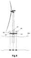
- Offshore-Windenergieanlage mit horizontaler Achse nach einem der Ansprüche 3 - 8, wobei ein erstes Gyroskop (41) an einer Vorderseite des Turmes (10) angeordnet ist und ein zweites Gyroskop (40) an einer Rückseite des Turmes (10) angeordnet ist.
- Offshore-Windenergieanlage mit horizontaler Achse nach einem der Ansprüche 3 - 9, wobei die Windenergieanlage eine Windenergieanlage des so genannten TLP ("Tension Leg Platform")-Typs ist.
- Offshore-Windenergieanlage mit horizontaler Achse nach Anspruch 10, weiterhin umfassend eine Vielzahl von sich radial nach außen bezüglich einer Längsachse des Turmes (10) erstreckenden Streben, wobei die Streben über dem Meeresspiegel angeordnet sind;
wobei für eine oder mehrere unter der Vielzahl von Streben, jede von den Streben eines von den Gyroskopen (40, 41) auf der Strebe angeordnet hat. - Offshore-Windenergieanlage mit horizontaler Achse nach einem der Ansprüche 3 - 11, weiterhin umfassend eine Vielzahl von Blättern mit einstellbarer Blattverstellung, Blattverstellungsantriebe zur Einstellung des Blattverstellungswinkels jedes Blattes, und Sensoren zur Erzeugung von Sensorsignalen, die Umgebungsbedingungen darstellen;
wobei die Steuereinheit angepasst ist, um Sensorsignale zu empfangen, die Umgebungsbedingungen darstellen:wobei die Steuereinheit angepasst ist, um, in Abhängigkeit von den empfangenen Sensorsignalen, die ermittelten Bewegungen in Komponenten zu teilen, die durch Blattverstellungsantrieb dämpfbar sind und Komponenten, die durch Gyroskopantrieb dämpfbar sind;wobei die Steuereinheit angepasst ist, um die Blattverstellungsantriebe mit geeigneten Steuersignalen für jeden Blattverstellungsantrieb zu versorgen, um den Blattverstellungswinkel seines Blattes einzustellen, um die durch Blattverstellungsantrieb dämpfbaren Komponenten mindestens teilweise zu dämpfen; undwobei die Steuereinheit angepasst ist, um die Versorgung von nur Gyroskopantrieben mit geeigneten Steuersignalen durchzuführen, um die durch Gyroskopantrieb dämpfbaren Komponenten mindestens teilweise zu dämpfen. - Verfahren zur Stabilisierung einer Offshore-Windenergieanlage mit horizontaler Achse nach einem der Ansprüche 3-11; wobei das Verfahren folgendes umfasst:den Empfang von Sensorsignalen durch die Steuereinheit, die ermittelte Bewegungen des Turmes (10) darstellen;die Versorgung von mindestens einem der ersten Gyroskopantriebe mit geeigneten Steuersignalen durch die Steuereinheit, damit der erste Gyroskopantrieb ein Drehmoment um die zugehörige Gyroskopeingangsachse (18) herum aufbringt, wobei das Drehmoment um die Eingangsachse (18) herum ein Drehmoment um die Ausgangsachse (19) des gleichen Gyroskops (23) herum erzeugt, welches die ermittelten Bewegungen des Turmes (10) mindestens teilweise dämpft.
- Verfahren nach Anspruch 13, wobei die Offshore-Windenergieanlage mit horizontaler Achse weiterhin eine Vielzahl von Blättern mit einstellbarer Blattverstellung, Blattverstellungsantriebe zur Einstellung des Blattverstellungswinkels jedes Blattes, und Sensoren zur Erzeugung von Sensorsignalen, die Umgebungsbedingungen darstellen, umfasst;
wobei das Verfahren weiterhin folgendes umfasst:den Empfang von Sensorsignalen, die Umgebungsbedingungen darstellen durch die Steuereinheit;die Teilung von den ermittelten Bewegungen in Komponenten, die durch Blattverstellungsantrieb dämpfbar sind und Komponenten, die durch Gyroskopantrieb dämpfbar sind durch die Steuereinheit, in Abhängigkeit von den empfangenen Sensorsignalen;die Versorgung von den Blattverstellungsantrieben mit geeigneten Steuersignalen durch die Steuereinheit, damit jeder Blattverstellungsantrieb den Blattverstellungswinkel seines Blattes einstellt, um die durch Blattverstellungsantrieb dämpfbaren Komponenten mindestens teilweise zu dämpfen; unddie Versorgung von nur Gyroskopantrieben mit geeigneten Steuersignalen durch die Steuereinheit, um die durch Gyroskopantrieb dämpfbaren Komponenten mindestens teilweise zu dämpfen.
Priority Applications (2)
| Application Number | Priority Date | Filing Date | Title |
|---|---|---|---|
| EP12382274.4A EP2685093B1 (de) | 2012-07-10 | 2012-07-10 | Windturbinenstabilisierung |
| US13/938,095 US9624906B2 (en) | 2012-07-10 | 2013-07-09 | Wind turbine stabilization |
Applications Claiming Priority (1)
| Application Number | Priority Date | Filing Date | Title |
|---|---|---|---|
| EP12382274.4A EP2685093B1 (de) | 2012-07-10 | 2012-07-10 | Windturbinenstabilisierung |
Publications (2)
| Publication Number | Publication Date |
|---|---|
| EP2685093A1 EP2685093A1 (de) | 2014-01-15 |
| EP2685093B1 true EP2685093B1 (de) | 2016-06-29 |
Family
ID=46581875
Family Applications (1)
| Application Number | Title | Priority Date | Filing Date |
|---|---|---|---|
| EP12382274.4A Not-in-force EP2685093B1 (de) | 2012-07-10 | 2012-07-10 | Windturbinenstabilisierung |
Country Status (2)
| Country | Link |
|---|---|
| US (1) | US9624906B2 (de) |
| EP (1) | EP2685093B1 (de) |
Families Citing this family (28)
| Publication number | Priority date | Publication date | Assignee | Title |
|---|---|---|---|---|
| EP2803853B1 (de) * | 2013-05-17 | 2015-09-02 | Siemens Aktiengesellschaft | Dämpfen von Windturbinenturmschwankungen unter Verwendung von gyroskopischen Kräften |
| US9590550B2 (en) * | 2014-01-16 | 2017-03-07 | General Electric Company | Systems and methods for adaptive control of excitation and generator systems |
| CN106460790B (zh) * | 2014-04-14 | 2019-02-01 | 远景能源(江苏)有限公司 | 具有浮动地基和位置调节的风力涡轮机结构控制系统及其方法 |
| NO2776494T3 (de) * | 2014-07-01 | 2018-09-29 | ||
| JP6510227B2 (ja) * | 2014-12-17 | 2019-05-08 | 株式会社日立製作所 | 風力発電システム |
| CN104816797B (zh) * | 2015-05-29 | 2019-03-26 | 刘莹 | 一种海上风力发电机组及其安装方法 |
| WO2016203421A1 (en) * | 2015-06-16 | 2016-12-22 | Orlando Lozzi | Self-stabilized offshore multi-blade wind generator with vertical axis |
| BR112019010894B1 (pt) * | 2016-11-29 | 2022-11-16 | Hywind As | Sistema de controle para uma estrutura de turbina eólica flutuante |
| CN107201991B (zh) * | 2017-06-05 | 2020-01-07 | 上海交通大学 | 一种新型海上风力机浮式平台 |
| EP3450752B1 (de) | 2017-09-04 | 2020-06-17 | Siemens Gamesa Renewable Energy A/S | Windturbine mit einer zugangsanordnung für eine gondel |
| DE102017124412A1 (de) * | 2017-10-19 | 2019-04-25 | Innogy Se | Soft-Soft Gründung für Offshore-Bauwerke |
| US11319925B2 (en) * | 2017-12-14 | 2022-05-03 | Vestas Wind Systems A/S | Tower damping in wind turbine power production |
| EP3743621B1 (de) | 2018-01-22 | 2022-03-23 | Vestas Wind Systems A/S | Verfahren zur steuerung eines mit einer windenergieanlage gekoppelten flugkörpers |
| US20210270236A1 (en) * | 2018-07-06 | 2021-09-02 | Vestas Wind Systems A/S | Multi-rotor wind turbine oscillation damping |
| EP3643595A1 (de) * | 2018-10-23 | 2020-04-29 | Siemens Gamesa Renewable Energy A/S | Kreisel zur stabilisierung von windturbinenbewegungen |
| US10994816B2 (en) | 2019-03-04 | 2021-05-04 | United States Of America As Represented By The Secretary Of The Navy | Floating device having active stabilization and method for active stabilization |
| DE102019124977A1 (de) * | 2019-09-17 | 2021-03-18 | Rwe Renewables Gmbh | Verfahren zum Installieren einer Offshore-Windenergievorrichtung |
| US11460002B2 (en) * | 2019-10-28 | 2022-10-04 | Siemens Gamesa Renewable Energy A/S | Blade vibration suppression system for a wind turbine and associated method |
| CN114787502A (zh) * | 2019-12-20 | 2022-07-22 | 维斯塔斯风力系统有限公司 | 用于阻尼位于海上的多转子风轮机移动的方法和装置 |
| WO2021240449A1 (en) * | 2020-05-29 | 2021-12-02 | F.Lli Righini S.R.L. | Floating structure |
| EP3933192A1 (de) | 2020-07-02 | 2022-01-05 | Siemens Gamesa Renewable Energy A/S | Schleppen einer schwimmenden windturbine |
| CN112302870B (zh) * | 2020-10-14 | 2022-03-29 | 明阳智慧能源集团股份公司 | 一种漂浮式风力发电机组稳定控制方法 |
| CN112628070B (zh) * | 2020-12-18 | 2021-12-28 | 明阳智慧能源集团股份公司 | 一种海上漂浮式风电机组浮台纵摇加阻控制方法与模块 |
| CN112648149B (zh) * | 2021-01-04 | 2022-07-01 | 上海电气风电集团股份有限公司 | 海上漂浮式风机基础及海上风机 |
| NO346706B1 (no) * | 2021-02-08 | 2022-11-28 | Oceangrid As | Flytende vindmøllekonstruksjon |
| CN114162263B (zh) * | 2021-12-17 | 2023-01-06 | 浙江大学 | 一种基于主动控制的漂浮式风力机系泊系统和控制方法 |
| CN115949554B (zh) * | 2022-09-30 | 2023-09-22 | 金风科技股份有限公司 | 风机基础、风力发电机组以及控制方法 |
| CN116002002A (zh) * | 2023-02-02 | 2023-04-25 | 大连理工大学 | 一种装配减载增稳装置的张力腿式风-波能互补浮式平台 |
Family Cites Families (18)
| Publication number | Priority date | Publication date | Assignee | Title |
|---|---|---|---|---|
| US769493A (en) * | 1903-05-11 | 1904-09-06 | Ernst Otto Schlick | Device for minimizing the oscillatory movements of ships. |
| US1071735A (en) * | 1912-05-04 | 1913-09-02 | Benjamin T Haagenson | Ice-breaking marine vessel. |
| US3576134A (en) * | 1968-02-19 | 1971-04-27 | Tetra Tech | Gyroscopic stabilizer having an adjustable spring |
| US4025230A (en) * | 1976-05-13 | 1977-05-24 | Lockheed Aircraft Corporation | Advanced control system for a rotor and/or a compound or rotary wing vehicle |
| US4582013A (en) * | 1980-12-23 | 1986-04-15 | The Holland Corporation | Self-adjusting wind power machine |
| DE3528672A1 (de) * | 1985-08-09 | 1987-02-19 | Kling Mauricio | Rotor fuer eine stroemungsmaschine |
| US4936750A (en) * | 1985-08-09 | 1990-06-26 | Heinz Alberto K | Rotor for a wind-driven generator |
| US6973847B2 (en) * | 2003-06-04 | 2005-12-13 | Gearloose Engineering, Inc. | Gyroscopic roll stabilizer for boats |
| US7240630B2 (en) * | 2003-10-08 | 2007-07-10 | Marine Motion Control, Llc | Gyrostabilizer for small boats |
| CN101287646B (zh) * | 2005-08-22 | 2010-12-08 | 科技投资股份有限公司 | 稳定装置 |
| US20070243063A1 (en) * | 2006-03-17 | 2007-10-18 | Schellstede Herman J | Offshore wind turbine structures and methods therefor |
| US8333561B2 (en) * | 2006-04-17 | 2012-12-18 | Richard Baron | Vertical axis wind turbine |
| WO2009049371A1 (en) * | 2007-10-16 | 2009-04-23 | Halcyon International Pty Ltd | Gyro-stabiliser |
| FR2931211A1 (fr) * | 2008-05-19 | 2009-11-20 | Roucar Gear Technologies Bv | Procede de collecte d'energie, unite de production electrique et eolienne s'y rapportant |
| NO329740B1 (no) * | 2009-04-16 | 2010-12-13 | Uni I Stavanger | Anordning ved flytende vindkraftverk |
| EP2536999B1 (de) * | 2010-02-17 | 2018-07-25 | Veem Ltd | Fehlertolerantes gefässstabilisator-steuersystem |
| JP5678391B2 (ja) * | 2010-11-05 | 2015-03-04 | 独立行政法人海上技術安全研究所 | 浮体式洋上風力発電施設 |
| JP5738644B2 (ja) * | 2011-03-25 | 2015-06-24 | 戸田建設株式会社 | 洋上風力発電設備の施工方法 |
-
2012
- 2012-07-10 EP EP12382274.4A patent/EP2685093B1/de not_active Not-in-force
-
2013
- 2013-07-09 US US13/938,095 patent/US9624906B2/en not_active Expired - Fee Related
Also Published As
| Publication number | Publication date |
|---|---|
| EP2685093A1 (de) | 2014-01-15 |
| US9624906B2 (en) | 2017-04-18 |
| US20140017083A1 (en) | 2014-01-16 |
Similar Documents
| Publication | Publication Date | Title |
|---|---|---|
| EP2685093B1 (de) | Windturbinenstabilisierung | |
| KR102638423B1 (ko) | 부유식 풍력 터빈 구조체를 위한 제어 시스템 | |
| EP2935876B1 (de) | Steuerung von bewegungen schwimmender windturbinen | |
| Cermelli et al. | WindFloat: a floating foundation for offshore wind turbines—part II: hydrodynamics analysis | |
| US20170037832A1 (en) | Wind Turbine with Floating Foundation and Position Regulating Control System and Method Thereof | |
| Huijs et al. | Comparison of model tests and coupled simulations for a semi-submersible floating wind turbine | |
| US20140202146A1 (en) | Method for operating a wave energy converter | |
| Bagbanci | Dynamic analysis of offshore floating wind turbines | |
| US20230271679A1 (en) | Towing of a floating wind turbine | |
| EP3943747A1 (de) | Überwachung von fastmachern einer schwimmenden windturbine | |
| Tian et al. | A novel dynamics analysis method for Spar-type floating offshore wind turbine | |
| US20230054921A1 (en) | Wind turbine control | |
| JP6786907B2 (ja) | 水中浮遊式発電装置の姿勢制御システムおよび姿勢制御方法 | |
| EP4267850A1 (de) | Steuerung einer schwimmenden windturbine unter nennwindgeschwindigkeit | |
| Song et al. | Development of a control algorithm for active control of rolling motion of a ship using a gyrostabilizer | |
| CN106741664A (zh) | 船舶登靠系统、控制船舶登靠系统保持平衡方法及运维船 | |
| WO2021094635A1 (es) | Sistema para adrizar y reducir movimientos en plataformas flotantes | |
| Haugvaldstad et al. | Testing of a new transport and installation method for offshore wind turbines | |
| JP2019094886A (ja) | 浮体式洋上風力発電装置 | |
| Yang et al. | PyraWind™: An Innovative Floating Offshore Wind Turbine (FOWT) Global Performance Analysis |
Legal Events
| Date | Code | Title | Description |
|---|---|---|---|
| PUAI | Public reference made under article 153(3) epc to a published international application that has entered the european phase |
Free format text: ORIGINAL CODE: 0009012 |
|
| AK | Designated contracting states |
Kind code of ref document: A1 Designated state(s): AL AT BE BG CH CY CZ DE DK EE ES FI FR GB GR HR HU IE IS IT LI LT LU LV MC MK MT NL NO PL PT RO RS SE SI SK SM TR |
|
| AX | Request for extension of the european patent |
Extension state: BA ME |
|
| 17P | Request for examination filed |
Effective date: 20140715 |
|
| RBV | Designated contracting states (corrected) |
Designated state(s): AL AT BE BG CH CY CZ DE DK EE ES FI FR GB GR HR HU IE IS IT LI LT LU LV MC MK MT NL NO PL PT RO RS SE SI SK SM TR |
|
| GRAP | Despatch of communication of intention to grant a patent |
Free format text: ORIGINAL CODE: EPIDOSNIGR1 |
|
| RIC1 | Information provided on ipc code assigned before grant |
Ipc: F03D 11/00 20060101ALI20150826BHEP Ipc: B63B 21/50 20060101ALI20150826BHEP Ipc: F03D 7/02 20060101AFI20150826BHEP Ipc: B63B 39/04 20060101ALI20150826BHEP |
|
| INTG | Intention to grant announced |
Effective date: 20150915 |
|
| GRAS | Grant fee paid |
Free format text: ORIGINAL CODE: EPIDOSNIGR3 |
|
| REG | Reference to a national code |
Ref country code: DE Ref legal event code: R079 Ref document number: 602012019933 Country of ref document: DE Free format text: PREVIOUS MAIN CLASS: F03D0007020000 Ipc: F03D0015000000 |
|
| RIC1 | Information provided on ipc code assigned before grant |
Ipc: B63B 39/04 20060101ALI20160404BHEP Ipc: B63B 21/50 20060101ALI20160404BHEP Ipc: F03D 80/00 20160101ALI20160404BHEP Ipc: F03D 15/00 20160101AFI20160404BHEP |
|
| GRAA | (expected) grant |
Free format text: ORIGINAL CODE: 0009210 |
|
| AK | Designated contracting states |
Kind code of ref document: B1 Designated state(s): AL AT BE BG CH CY CZ DE DK EE ES FI FR GB GR HR HU IE IS IT LI LT LU LV MC MK MT NL NO PL PT RO RS SE SI SK SM TR |
|
| REG | Reference to a national code |
Ref country code: GB Ref legal event code: FG4D |
|
| REG | Reference to a national code |
Ref country code: CH Ref legal event code: EP |
|
| REG | Reference to a national code |
Ref country code: AT Ref legal event code: REF Ref document number: 809325 Country of ref document: AT Kind code of ref document: T Effective date: 20160715 |
|
| REG | Reference to a national code |
Ref country code: FR Ref legal event code: PLFP Year of fee payment: 5 |
|
| REG | Reference to a national code |
Ref country code: IE Ref legal event code: FG4D |
|
| REG | Reference to a national code |
Ref country code: DE Ref legal event code: R096 Ref document number: 602012019933 Country of ref document: DE |
|
| REG | Reference to a national code |
Ref country code: LT Ref legal event code: MG4D |
|
| PG25 | Lapsed in a contracting state [announced via postgrant information from national office to epo] |
Ref country code: FI Free format text: LAPSE BECAUSE OF FAILURE TO SUBMIT A TRANSLATION OF THE DESCRIPTION OR TO PAY THE FEE WITHIN THE PRESCRIBED TIME-LIMIT Effective date: 20160629 Ref country code: NO Free format text: LAPSE BECAUSE OF FAILURE TO SUBMIT A TRANSLATION OF THE DESCRIPTION OR TO PAY THE FEE WITHIN THE PRESCRIBED TIME-LIMIT Effective date: 20160929 Ref country code: LT Free format text: LAPSE BECAUSE OF FAILURE TO SUBMIT A TRANSLATION OF THE DESCRIPTION OR TO PAY THE FEE WITHIN THE PRESCRIBED TIME-LIMIT Effective date: 20160629 |
|
| PGFP | Annual fee paid to national office [announced via postgrant information from national office to epo] |
Ref country code: DE Payment date: 20160726 Year of fee payment: 5 |
|
| REG | Reference to a national code |
Ref country code: NL Ref legal event code: MP Effective date: 20160629 |
|
| RAP2 | Party data changed (patent owner data changed or rights of a patent transferred) |
Owner name: ALSTOM RENEWABLES TECHNOLOGIES WIND B.V. |
|
| PG25 | Lapsed in a contracting state [announced via postgrant information from national office to epo] |
Ref country code: GR Free format text: LAPSE BECAUSE OF FAILURE TO SUBMIT A TRANSLATION OF THE DESCRIPTION OR TO PAY THE FEE WITHIN THE PRESCRIBED TIME-LIMIT Effective date: 20160930 Ref country code: RS Free format text: LAPSE BECAUSE OF FAILURE TO SUBMIT A TRANSLATION OF THE DESCRIPTION OR TO PAY THE FEE WITHIN THE PRESCRIBED TIME-LIMIT Effective date: 20160629 Ref country code: LV Free format text: LAPSE BECAUSE OF FAILURE TO SUBMIT A TRANSLATION OF THE DESCRIPTION OR TO PAY THE FEE WITHIN THE PRESCRIBED TIME-LIMIT Effective date: 20160629 Ref country code: NL Free format text: LAPSE BECAUSE OF FAILURE TO SUBMIT A TRANSLATION OF THE DESCRIPTION OR TO PAY THE FEE WITHIN THE PRESCRIBED TIME-LIMIT Effective date: 20160629 Ref country code: HR Free format text: LAPSE BECAUSE OF FAILURE TO SUBMIT A TRANSLATION OF THE DESCRIPTION OR TO PAY THE FEE WITHIN THE PRESCRIBED TIME-LIMIT Effective date: 20160629 Ref country code: SE Free format text: LAPSE BECAUSE OF FAILURE TO SUBMIT A TRANSLATION OF THE DESCRIPTION OR TO PAY THE FEE WITHIN THE PRESCRIBED TIME-LIMIT Effective date: 20160629 |
|
| REG | Reference to a national code |
Ref country code: AT Ref legal event code: MK05 Ref document number: 809325 Country of ref document: AT Kind code of ref document: T Effective date: 20160629 |
|
| PG25 | Lapsed in a contracting state [announced via postgrant information from national office to epo] |
Ref country code: BE Free format text: LAPSE BECAUSE OF NON-PAYMENT OF DUE FEES Effective date: 20160731 |
|
| PG25 | Lapsed in a contracting state [announced via postgrant information from national office to epo] |
Ref country code: EE Free format text: LAPSE BECAUSE OF FAILURE TO SUBMIT A TRANSLATION OF THE DESCRIPTION OR TO PAY THE FEE WITHIN THE PRESCRIBED TIME-LIMIT Effective date: 20160629 Ref country code: RO Free format text: LAPSE BECAUSE OF FAILURE TO SUBMIT A TRANSLATION OF THE DESCRIPTION OR TO PAY THE FEE WITHIN THE PRESCRIBED TIME-LIMIT Effective date: 20160629 Ref country code: IS Free format text: LAPSE BECAUSE OF FAILURE TO SUBMIT A TRANSLATION OF THE DESCRIPTION OR TO PAY THE FEE WITHIN THE PRESCRIBED TIME-LIMIT Effective date: 20161029 Ref country code: SK Free format text: LAPSE BECAUSE OF FAILURE TO SUBMIT A TRANSLATION OF THE DESCRIPTION OR TO PAY THE FEE WITHIN THE PRESCRIBED TIME-LIMIT Effective date: 20160629 Ref country code: CZ Free format text: LAPSE BECAUSE OF FAILURE TO SUBMIT A TRANSLATION OF THE DESCRIPTION OR TO PAY THE FEE WITHIN THE PRESCRIBED TIME-LIMIT Effective date: 20160629 Ref country code: IT Free format text: LAPSE BECAUSE OF FAILURE TO SUBMIT A TRANSLATION OF THE DESCRIPTION OR TO PAY THE FEE WITHIN THE PRESCRIBED TIME-LIMIT Effective date: 20160629 |
|
| REG | Reference to a national code |
Ref country code: GB Ref legal event code: 732E Free format text: REGISTERED BETWEEN 20170105 AND 20170111 |
|
| PG25 | Lapsed in a contracting state [announced via postgrant information from national office to epo] |
Ref country code: BE Free format text: LAPSE BECAUSE OF FAILURE TO SUBMIT A TRANSLATION OF THE DESCRIPTION OR TO PAY THE FEE WITHIN THE PRESCRIBED TIME-LIMIT Effective date: 20160629 Ref country code: ES Free format text: LAPSE BECAUSE OF FAILURE TO SUBMIT A TRANSLATION OF THE DESCRIPTION OR TO PAY THE FEE WITHIN THE PRESCRIBED TIME-LIMIT Effective date: 20160629 Ref country code: SM Free format text: LAPSE BECAUSE OF FAILURE TO SUBMIT A TRANSLATION OF THE DESCRIPTION OR TO PAY THE FEE WITHIN THE PRESCRIBED TIME-LIMIT Effective date: 20160629 Ref country code: AT Free format text: LAPSE BECAUSE OF FAILURE TO SUBMIT A TRANSLATION OF THE DESCRIPTION OR TO PAY THE FEE WITHIN THE PRESCRIBED TIME-LIMIT Effective date: 20160629 Ref country code: PT Free format text: LAPSE BECAUSE OF FAILURE TO SUBMIT A TRANSLATION OF THE DESCRIPTION OR TO PAY THE FEE WITHIN THE PRESCRIBED TIME-LIMIT Effective date: 20161031 Ref country code: PL Free format text: LAPSE BECAUSE OF FAILURE TO SUBMIT A TRANSLATION OF THE DESCRIPTION OR TO PAY THE FEE WITHIN THE PRESCRIBED TIME-LIMIT Effective date: 20160629 |
|
| REG | Reference to a national code |
Ref country code: CH Ref legal event code: PL |
|
| RAP2 | Party data changed (patent owner data changed or rights of a patent transferred) |
Owner name: ALSTOM RENEWABLE TECHNOLOGIES |
|
| REG | Reference to a national code |
Ref country code: DE Ref legal event code: R097 Ref document number: 602012019933 Country of ref document: DE |
|
| PG25 | Lapsed in a contracting state [announced via postgrant information from national office to epo] |
Ref country code: LI Free format text: LAPSE BECAUSE OF NON-PAYMENT OF DUE FEES Effective date: 20160731 Ref country code: CH Free format text: LAPSE BECAUSE OF NON-PAYMENT OF DUE FEES Effective date: 20160731 |
|
| REG | Reference to a national code |
Ref country code: IE Ref legal event code: MM4A |
|
| PLBE | No opposition filed within time limit |
Free format text: ORIGINAL CODE: 0009261 |
|
| STAA | Information on the status of an ep patent application or granted ep patent |
Free format text: STATUS: NO OPPOSITION FILED WITHIN TIME LIMIT |
|
| PG25 | Lapsed in a contracting state [announced via postgrant information from national office to epo] |
Ref country code: DK Free format text: LAPSE BECAUSE OF FAILURE TO SUBMIT A TRANSLATION OF THE DESCRIPTION OR TO PAY THE FEE WITHIN THE PRESCRIBED TIME-LIMIT Effective date: 20160629 |
|
| 26N | No opposition filed |
Effective date: 20170330 |
|
| STAA | Information on the status of an ep patent application or granted ep patent |
Free format text: STATUS: NO OPPOSITION FILED WITHIN TIME LIMIT |
|
| REG | Reference to a national code |
Ref country code: FR Ref legal event code: PLFP Year of fee payment: 6 |
|
| PG25 | Lapsed in a contracting state [announced via postgrant information from national office to epo] |
Ref country code: IE Free format text: LAPSE BECAUSE OF NON-PAYMENT OF DUE FEES Effective date: 20160710 |
|
| PG25 | Lapsed in a contracting state [announced via postgrant information from national office to epo] |
Ref country code: LU Free format text: LAPSE BECAUSE OF NON-PAYMENT OF DUE FEES Effective date: 20160710 Ref country code: BG Free format text: LAPSE BECAUSE OF FAILURE TO SUBMIT A TRANSLATION OF THE DESCRIPTION OR TO PAY THE FEE WITHIN THE PRESCRIBED TIME-LIMIT Effective date: 20160929 Ref country code: SI Free format text: LAPSE BECAUSE OF FAILURE TO SUBMIT A TRANSLATION OF THE DESCRIPTION OR TO PAY THE FEE WITHIN THE PRESCRIBED TIME-LIMIT Effective date: 20160629 |
|
| REG | Reference to a national code |
Ref country code: DE Ref legal event code: R119 Ref document number: 602012019933 Country of ref document: DE |
|
| REG | Reference to a national code |
Ref country code: FR Ref legal event code: CD Owner name: GE RENEWABLE TECHNOLOGIES WIND B.V., NL Effective date: 20180219 Ref country code: FR Ref legal event code: TP Owner name: GE RENEWABLE TECHNOLOGIES WIND B.V., NL Effective date: 20180219 |
|
| REG | Reference to a national code |
Ref country code: GB Ref legal event code: 732E Free format text: REGISTERED BETWEEN 20180315 AND 20180326 |
|
| PG25 | Lapsed in a contracting state [announced via postgrant information from national office to epo] |
Ref country code: DE Free format text: LAPSE BECAUSE OF NON-PAYMENT OF DUE FEES Effective date: 20180201 |
|
| PG25 | Lapsed in a contracting state [announced via postgrant information from national office to epo] |
Ref country code: HU Free format text: LAPSE BECAUSE OF FAILURE TO SUBMIT A TRANSLATION OF THE DESCRIPTION OR TO PAY THE FEE WITHIN THE PRESCRIBED TIME-LIMIT; INVALID AB INITIO Effective date: 20120710 Ref country code: CY Free format text: LAPSE BECAUSE OF FAILURE TO SUBMIT A TRANSLATION OF THE DESCRIPTION OR TO PAY THE FEE WITHIN THE PRESCRIBED TIME-LIMIT Effective date: 20160629 |
|
| REG | Reference to a national code |
Ref country code: FR Ref legal event code: PLFP Year of fee payment: 7 |
|
| PG25 | Lapsed in a contracting state [announced via postgrant information from national office to epo] |
Ref country code: MK Free format text: LAPSE BECAUSE OF FAILURE TO SUBMIT A TRANSLATION OF THE DESCRIPTION OR TO PAY THE FEE WITHIN THE PRESCRIBED TIME-LIMIT Effective date: 20160629 Ref country code: TR Free format text: LAPSE BECAUSE OF FAILURE TO SUBMIT A TRANSLATION OF THE DESCRIPTION OR TO PAY THE FEE WITHIN THE PRESCRIBED TIME-LIMIT Effective date: 20160629 Ref country code: MT Free format text: LAPSE BECAUSE OF NON-PAYMENT OF DUE FEES Effective date: 20160731 Ref country code: MC Free format text: LAPSE BECAUSE OF FAILURE TO SUBMIT A TRANSLATION OF THE DESCRIPTION OR TO PAY THE FEE WITHIN THE PRESCRIBED TIME-LIMIT Effective date: 20160629 |
|
| PG25 | Lapsed in a contracting state [announced via postgrant information from national office to epo] |
Ref country code: AL Free format text: LAPSE BECAUSE OF FAILURE TO SUBMIT A TRANSLATION OF THE DESCRIPTION OR TO PAY THE FEE WITHIN THE PRESCRIBED TIME-LIMIT Effective date: 20160629 |
|
| PGFP | Annual fee paid to national office [announced via postgrant information from national office to epo] |
Ref country code: FR Payment date: 20190621 Year of fee payment: 8 |
|
| PGFP | Annual fee paid to national office [announced via postgrant information from national office to epo] |
Ref country code: GB Payment date: 20190624 Year of fee payment: 8 |
|
| GBPC | Gb: european patent ceased through non-payment of renewal fee |
Effective date: 20200710 |
|
| PG25 | Lapsed in a contracting state [announced via postgrant information from national office to epo] |
Ref country code: FR Free format text: LAPSE BECAUSE OF NON-PAYMENT OF DUE FEES Effective date: 20200731 Ref country code: GB Free format text: LAPSE BECAUSE OF NON-PAYMENT OF DUE FEES Effective date: 20200710 |