EP2685086B1 - Engine starting strategy to avoid resonant frequency - Google Patents
Engine starting strategy to avoid resonant frequency Download PDFInfo
- Publication number
- EP2685086B1 EP2685086B1 EP13003204.8A EP13003204A EP2685086B1 EP 2685086 B1 EP2685086 B1 EP 2685086B1 EP 13003204 A EP13003204 A EP 13003204A EP 2685086 B1 EP2685086 B1 EP 2685086B1
- Authority
- EP
- European Patent Office
- Prior art keywords
- engine
- hybrid motor
- speed
- clutch
- machine
- Prior art date
- Legal status (The legal status is an assumption and is not a legal conclusion. Google has not performed a legal analysis and makes no representation as to the accuracy of the status listed.)
- Active
Links
- 238000000034 method Methods 0.000 claims description 21
- 239000007858 starting material Substances 0.000 claims description 17
- 238000012546 transfer Methods 0.000 claims description 8
- 230000001960 triggered effect Effects 0.000 claims description 4
- 239000000463 material Substances 0.000 claims description 3
- 230000007246 mechanism Effects 0.000 description 14
- 230000005540 biological transmission Effects 0.000 description 13
- 238000002485 combustion reaction Methods 0.000 description 7
- 230000003071 parasitic effect Effects 0.000 description 6
- 230000000254 damaging effect Effects 0.000 description 3
- 238000013461 design Methods 0.000 description 3
- 230000000694 effects Effects 0.000 description 3
- 238000010276 construction Methods 0.000 description 2
- 230000005611 electricity Effects 0.000 description 2
- 239000000446 fuel Substances 0.000 description 2
- 238000009987 spinning Methods 0.000 description 2
- 230000008901 benefit Effects 0.000 description 1
- 230000001680 brushing effect Effects 0.000 description 1
- 239000002826 coolant Substances 0.000 description 1
- 230000001351 cycling effect Effects 0.000 description 1
- 230000001419 dependent effect Effects 0.000 description 1
- 238000011156 evaluation Methods 0.000 description 1
- 238000009313 farming Methods 0.000 description 1
- 239000012530 fluid Substances 0.000 description 1
- 230000007774 longterm Effects 0.000 description 1
- 238000005065 mining Methods 0.000 description 1
- 238000012986 modification Methods 0.000 description 1
- 230000004048 modification Effects 0.000 description 1
- 238000012544 monitoring process Methods 0.000 description 1
- 230000010355 oscillation Effects 0.000 description 1
- 230000008569 process Effects 0.000 description 1
- 238000012545 processing Methods 0.000 description 1
- 230000004044 response Effects 0.000 description 1
Images


Classifications
-
- F—MECHANICAL ENGINEERING; LIGHTING; HEATING; WEAPONS; BLASTING
- F02—COMBUSTION ENGINES; HOT-GAS OR COMBUSTION-PRODUCT ENGINE PLANTS
- F02N—STARTING OF COMBUSTION ENGINES; STARTING AIDS FOR SUCH ENGINES, NOT OTHERWISE PROVIDED FOR
- F02N11/00—Starting of engines by means of electric motors
- F02N11/08—Circuits or control means specially adapted for starting of engines
- F02N11/0851—Circuits or control means specially adapted for starting of engines characterised by means for controlling the engagement or disengagement between engine and starter, e.g. meshing of pinion and engine gear
-
- B—PERFORMING OPERATIONS; TRANSPORTING
- B60—VEHICLES IN GENERAL
- B60W—CONJOINT CONTROL OF VEHICLE SUB-UNITS OF DIFFERENT TYPE OR DIFFERENT FUNCTION; CONTROL SYSTEMS SPECIALLY ADAPTED FOR HYBRID VEHICLES; ROAD VEHICLE DRIVE CONTROL SYSTEMS FOR PURPOSES NOT RELATED TO THE CONTROL OF A PARTICULAR SUB-UNIT
- B60W10/00—Conjoint control of vehicle sub-units of different type or different function
- B60W10/04—Conjoint control of vehicle sub-units of different type or different function including control of propulsion units
- B60W10/06—Conjoint control of vehicle sub-units of different type or different function including control of propulsion units including control of combustion engines
-
- B—PERFORMING OPERATIONS; TRANSPORTING
- B60—VEHICLES IN GENERAL
- B60W—CONJOINT CONTROL OF VEHICLE SUB-UNITS OF DIFFERENT TYPE OR DIFFERENT FUNCTION; CONTROL SYSTEMS SPECIALLY ADAPTED FOR HYBRID VEHICLES; ROAD VEHICLE DRIVE CONTROL SYSTEMS FOR PURPOSES NOT RELATED TO THE CONTROL OF A PARTICULAR SUB-UNIT
- B60W10/00—Conjoint control of vehicle sub-units of different type or different function
- B60W10/04—Conjoint control of vehicle sub-units of different type or different function including control of propulsion units
- B60W10/08—Conjoint control of vehicle sub-units of different type or different function including control of propulsion units including control of electric propulsion units, e.g. motors or generators
-
- B—PERFORMING OPERATIONS; TRANSPORTING
- B60—VEHICLES IN GENERAL
- B60W—CONJOINT CONTROL OF VEHICLE SUB-UNITS OF DIFFERENT TYPE OR DIFFERENT FUNCTION; CONTROL SYSTEMS SPECIALLY ADAPTED FOR HYBRID VEHICLES; ROAD VEHICLE DRIVE CONTROL SYSTEMS FOR PURPOSES NOT RELATED TO THE CONTROL OF A PARTICULAR SUB-UNIT
- B60W20/00—Control systems specially adapted for hybrid vehicles
- B60W20/10—Controlling the power contribution of each of the prime movers to meet required power demand
- B60W20/15—Control strategies specially adapted for achieving a particular effect
-
- B—PERFORMING OPERATIONS; TRANSPORTING
- B60—VEHICLES IN GENERAL
- B60W—CONJOINT CONTROL OF VEHICLE SUB-UNITS OF DIFFERENT TYPE OR DIFFERENT FUNCTION; CONTROL SYSTEMS SPECIALLY ADAPTED FOR HYBRID VEHICLES; ROAD VEHICLE DRIVE CONTROL SYSTEMS FOR PURPOSES NOT RELATED TO THE CONTROL OF A PARTICULAR SUB-UNIT
- B60W30/00—Purposes of road vehicle drive control systems not related to the control of a particular sub-unit, e.g. of systems using conjoint control of vehicle sub-units, or advanced driver assistance systems for ensuring comfort, stability and safety or drive control systems for propelling or retarding the vehicle
- B60W30/18—Propelling the vehicle
- B60W30/20—Reducing vibrations in the driveline
-
- F—MECHANICAL ENGINEERING; LIGHTING; HEATING; WEAPONS; BLASTING
- F02—COMBUSTION ENGINES; HOT-GAS OR COMBUSTION-PRODUCT ENGINE PLANTS
- F02N—STARTING OF COMBUSTION ENGINES; STARTING AIDS FOR SUCH ENGINES, NOT OTHERWISE PROVIDED FOR
- F02N11/00—Starting of engines by means of electric motors
- F02N11/08—Circuits or control means specially adapted for starting of engines
-
- F—MECHANICAL ENGINEERING; LIGHTING; HEATING; WEAPONS; BLASTING
- F02—COMBUSTION ENGINES; HOT-GAS OR COMBUSTION-PRODUCT ENGINE PLANTS
- F02N—STARTING OF COMBUSTION ENGINES; STARTING AIDS FOR SUCH ENGINES, NOT OTHERWISE PROVIDED FOR
- F02N15/00—Other power-operated starting apparatus; Component parts, details, or accessories, not provided for in, or of interest apart from groups F02N5/00 - F02N13/00
- F02N15/02—Gearing between starting-engines and started engines; Engagement or disengagement thereof
- F02N15/022—Gearing between starting-engines and started engines; Engagement or disengagement thereof the starter comprising an intermediate clutch
-
- F—MECHANICAL ENGINEERING; LIGHTING; HEATING; WEAPONS; BLASTING
- F02—COMBUSTION ENGINES; HOT-GAS OR COMBUSTION-PRODUCT ENGINE PLANTS
- F02N—STARTING OF COMBUSTION ENGINES; STARTING AIDS FOR SUCH ENGINES, NOT OTHERWISE PROVIDED FOR
- F02N5/00—Starting apparatus having mechanical power storage
- F02N5/04—Starting apparatus having mechanical power storage of inertia type
-
- B—PERFORMING OPERATIONS; TRANSPORTING
- B60—VEHICLES IN GENERAL
- B60W—CONJOINT CONTROL OF VEHICLE SUB-UNITS OF DIFFERENT TYPE OR DIFFERENT FUNCTION; CONTROL SYSTEMS SPECIALLY ADAPTED FOR HYBRID VEHICLES; ROAD VEHICLE DRIVE CONTROL SYSTEMS FOR PURPOSES NOT RELATED TO THE CONTROL OF A PARTICULAR SUB-UNIT
- B60W30/00—Purposes of road vehicle drive control systems not related to the control of a particular sub-unit, e.g. of systems using conjoint control of vehicle sub-units, or advanced driver assistance systems for ensuring comfort, stability and safety or drive control systems for propelling or retarding the vehicle
- B60W30/18—Propelling the vehicle
- B60W30/20—Reducing vibrations in the driveline
- B60W2030/206—Reducing vibrations in the driveline related or induced by the engine
-
- B—PERFORMING OPERATIONS; TRANSPORTING
- B60—VEHICLES IN GENERAL
- B60W—CONJOINT CONTROL OF VEHICLE SUB-UNITS OF DIFFERENT TYPE OR DIFFERENT FUNCTION; CONTROL SYSTEMS SPECIALLY ADAPTED FOR HYBRID VEHICLES; ROAD VEHICLE DRIVE CONTROL SYSTEMS FOR PURPOSES NOT RELATED TO THE CONTROL OF A PARTICULAR SUB-UNIT
- B60W2510/00—Input parameters relating to a particular sub-units
- B60W2510/06—Combustion engines, Gas turbines
- B60W2510/0638—Engine speed
-
- F—MECHANICAL ENGINEERING; LIGHTING; HEATING; WEAPONS; BLASTING
- F02—COMBUSTION ENGINES; HOT-GAS OR COMBUSTION-PRODUCT ENGINE PLANTS
- F02N—STARTING OF COMBUSTION ENGINES; STARTING AIDS FOR SUCH ENGINES, NOT OTHERWISE PROVIDED FOR
- F02N2200/00—Parameters used for control of starting apparatus
- F02N2200/04—Parameters used for control of starting apparatus said parameters being related to the starter motor
- F02N2200/041—Starter speed
-
- Y—GENERAL TAGGING OF NEW TECHNOLOGICAL DEVELOPMENTS; GENERAL TAGGING OF CROSS-SECTIONAL TECHNOLOGIES SPANNING OVER SEVERAL SECTIONS OF THE IPC; TECHNICAL SUBJECTS COVERED BY FORMER USPC CROSS-REFERENCE ART COLLECTIONS [XRACs] AND DIGESTS
- Y02—TECHNOLOGIES OR APPLICATIONS FOR MITIGATION OR ADAPTATION AGAINST CLIMATE CHANGE
- Y02T—CLIMATE CHANGE MITIGATION TECHNOLOGIES RELATED TO TRANSPORTATION
- Y02T10/00—Road transport of goods or passengers
- Y02T10/60—Other road transportation technologies with climate change mitigation effect
- Y02T10/62—Hybrid vehicles
Definitions
- This patent disclosure relates generally to engines and, more particularly, to starting engines.
- Engine driven machines can experience resonance when the vibration frequency of the driving part, such as a motor or engine, matches the mechanical resonant frequencies of the components of the machine.
- Many large machines experience resonant frequencies within the powertrains as a result of vibration caused by the speed output of an engine as the cylinders of the engine go through the combustion cycle.
- the amplitude of the torque applied to the component parts increases dramatically, which can damage mechanical components of a machine.
- Engineers have learned to design power systems so that the resonant frequencies in the powertrain occur at engine speeds outside the normal operating range of a particular machine to avoid damage.
- EP 1 113 169 A1 discloses a starter device for an internal combustion engine and method for controlling the same and was used as a basis for the preamble of claim 1.
- the starter control method uses a drive train control with evaluation of the operating parameters of the internal combustion engine, e.g. the camshaft and crankshaft angles and the operating parameters of the components of the starter device, for providing required values for setting devices for adjusting the starter device components.
- resonant frequencies can still occur during lower start-up engine speeds as the engine attempts to overcome the large inertial forces required to rotate large machine components and parasitic load caused by pump drag, engine friction, and other non-inertial loads. Achieving an engine speed above which machine components experience resonance is particularly difficult in cold weather, when an engine can fail to speed up successfully through the resonant frequency engine speeds.
- a machine is provided as set forth in claim 1.
- a method of operating a machine is provided as set forth in claim 6. Preferred embodiments of the present invention may be gathered from the dependent claims.
- the machine 100 has a powertrain 101 that includes components such as an engine 102, a crankshaft 103, a clutch 112, a clutch shaft 105, auxiliary mechanisms 116, and a transmission 114.
- the powertrain 101 can also include other components not illustrated herein.
- an engine starter 104 is connected to the engine 102.
- the engine starter 104 can be an electric motor engaged by the machine's 100 ignition switch 106, but could also be any suitable kinetic energy source capable of starting an engine.
- the engine starter 104 is connected to an electronic power source 108 such as a battery or other electronic storage, that supplies the engine starter with electric power.
- the engine 102 can also have injectors 110 that inject fuel, air, or other materials into the engine cylinders 109 for combustion.
- the embodiment schematically represented in FIG. 1 shows an engine 102 with eight cylinders 109 and eight injectors 110, though any number of injectors or cylinders is contemplated, and each cylinder can have more than one injector depending on the specific engine design.
- Pistons inside the cylinders 109 are connected to a crankshaft 103.
- the crankshaft 103 rotates as a result of the combustion within the cylinders 109 and corresponding piston oscillation.
- the clutch 112 connects the engine 102 to the transmission 114 between the crankshaft 103 and the clutch shaft 105, with the crankshaft connecting the engine to the clutch, and the clutch shaft connecting the transmission to the clutch.
- the clutch 112 can be engaged or disengaged either automatically by an electronic control module 124 or by the machine 100 operator. Engaging the clutch 112 locks the crankshaft 103 and the clutch shaft 105 so that both rotate substantially at the same rate, applying power from the engine 102 to other components.
- the clutch 112 When the clutch 112 is engaged, the engine 102 can apply power to the transmission 114.
- the clutch 112 is disengaged, no power from the engine 102 is applied to the transmission 114 because the clutch does not transfer crankshaft 103 rotation to the clutch shaft 105.
- the clutch 112 also connects the engine 102 to auxiliary mechanisms 116.
- Auxiliary mechanisms 116 can be compressors, pumps for coolant, oil and other fluids, compressors, or any other mechanisms the machine 100 uses that require power. In such embodiments, engaging and disengaging the clutch 112 enables and disables, respectively, the application of power from the engine 102 to the auxiliary mechanisms 116. While the embodiment illustrated in FIG. 1 shows three auxiliary mechanisms 116, it is contemplated that any number of auxiliary mechanisms can be included. In other embodiments, it is contemplated that additional auxiliary clutches 113 separate from the clutch 112 can connect the engine 102 to the auxiliary mechanisms 116.
- the auxiliary mechanisms 116 can be connected or disconnected from the engine 102 independently of whether the transmission 114 is connected or disconnected from the engine.
- the embodiment in FIG. 1 shows auxiliary clutches 113 between the auxiliary mechanisms 116 and the clutch 112; however, the auxiliary clutches can also be located between the engine 102 and the clutch, or bypass the clutch altogether by connecting the engine directly to the auxiliary mechanisms with the auxiliary clutches.
- the machine 100 also includes a hybrid motor 118 that is connected to the transmission 114, auxiliary mechanisms 116, the engine 102, or any other powertrain 101 components.
- the hybrid motor 118 can apply power to the powertrain 101 components separately from or in addition to the engine 102, depending on whether the clutch 112 is engaged or disengaged, as is described in greater detail below.
- the hybrid motor 118 can apply power directly to the engine 102 or to the engine through other powertrain 101 components.
- the hybrid motor 118 receives energy from a stored energy source 120.
- the stored energy source 120 stores energy from a direct source, such as an electrical grid, or energy generated by the vehicle.
- the hybrid motor 118 uses the stored energy to apply power to powertrain 101 components.
- additional clutches can separate the hybrid motor 118 from the powertrain 101 components.
- the additional clutches engage and disengage to allow the hybrid motor 118 to apply power to certain powertrain 101 components and not other powertrain components at a given time, or apply power to all or none of the power train components at a given time.
- triggering the ignition switch 106 completes a circuit that allows electricity to flow from an electric power source 108 to the engine starter 104.
- the electric power source 108 can be a battery, a hard electrical line, or any other suitable source of electricity.
- the engine starter 104 converts the electric power from the electric power source 108 into kinetic energy to begin cycling the engine 102.
- the injectors 110 begin injecting fuel and air into the engine's 102 cylinders 109 to begin and maintain the combustion process. Pistons in the cylinders 109 oscillate in response to the combustion process and rotate the crankshaft 103.
- the rotating crankshaft 103 applies power to the powertrain 101 components to overcome resistant inertial forces and the parasitic load of those components and cause them to rotate. Parasitic load can result from pump drag, engine friction, or other non-inertial loads on the engine.
- the speed of the engine 102 can be described as the number of revolutions the engine causes the crankshaft 103 to make per minute (RPM).
- the engine 102 is capable of outputting a wide range of engine speeds.
- the vibration frequency caused by the engine can match the powertrain's 101 mechanical resonant frequencies.
- the powertrain 101 components can experience large amplitudes of torque, which can damage the components.
- the vibration frequency caused by the transmission 114 as it rotates can cause resonance in the powertrain 101.
- the transmission 114 speeds that cause resonance are identified as resonant frequency transmission 114 speeds in this disclosure.
- the rotational speed of the powertrain 101 components may be determined using rotary encoders or other suitable rotation sensors.
- the embodiment illustrated in FIG. 1 shows a rotary sensor 122 connected to the electronic control module 124.
- the electronic control module 124 may also be connected operatively to both the engine 102, the hybrid motor 118, and the clutch 112, and is configured to control the activity of those and other components.
- Some embodiments may implement additional sensors, such as torque sensors, that measure the torque levels experienced by the powertrain 101 components and communicate those levels back to the electronic control module 124.
- the torque levels caused by the engine 102 applying power to the powertrain 101 are engine torque levels
- the torque levels caused by the hybrid motor 118 applying power to the powertrain are hybrid torque levels.
- Hybrid torque sensors 123 can sense the hybrid torque levels, and engine torque sensors 125 can sense the engine torque levels.
- the engine torque sensors 125 are operatively associated with the electronic control module 124 and adapted to send signals indicative of the engine torque levels to the electronic control module.
- the hybrid torque sensors 123 are also operatively associated with the electronic control module 124 and adapted to send signals indicative of the hybrid torque levels to the electronic control module.
- other rotary sensors can be used, for example, on the clutch shaft 105, to send signals to the electronic control module 124 to monitor the transmission 114 speed.
- the operative connection between the sensors and the electronic control module 124 can be made in any suitable manner, for example, wirelessly or by a hardwired electronic connection.
- the engine 102 is connected to the hybrid motor 118 through the clutch 112 such that the hybrid motor can apply power to the engine when the clutch is engaged.
- the clutch 112 disengages before, as, or after the ignition switch 106 is triggered. Triggering the ignition switch 106 starts the hybrid motor 118 and causes the hybrid motor to begin spinning through various hybrid motor speeds. As the hybrid motor 118 speed increases, the kinetic energy of the hybrid motor increases as well. At a certain, predetermined hybrid motor 118 speed, the clutch 112 is engaged and the kinetic energy of the hybrid motor is transferred to the engine 102.
- the predetermined hybrid motor 118 speed is calculated by determining the hybrid motor speed for which the kinetic energy of the hybrid motor is sufficient to transfer enough power to the engine 102 to speed the engine to an engine speed that exceeds the resonant frequency engine speed. In other words, when the clutch 112 is engaged, the hybrid motor 118 provides enough kinetic energy to the engine 102 to quickly speed the engine through the resonant frequency engine speed, which limits the damaging effects on the powertrain 101 components.
- the hybrid motor 118 is operatively connected to at least one powertrain 101 component, such as the transmission 114, the auxiliary mechanisms 116, or other components.
- the powertrain 101 components are operatively connected to the engine when the clutch 112 is engaged, but not connected to the engine when the clutch is disengaged.
- the hybrid motor 118 applies power to these components, they speed up and develop kinetic energy of their own.
- the powertrain 101 component kinetic energy increases as the hybrid motor 118 spins the components at increasing speeds. With the clutch 112 is disengaged, the hybrid motor 118 can apply power to the powertrain 101 components and spin them up to speed without the burden of the engine 102.
- the powertrain component kinetic energy is transferred to the engine 102.
- the powertrain 101 component kinetic energy can be determined based on the specific hybrid motor 118 speed. At a certain hybrid motor 118 speed, the powertrain 101 component kinetic energy is such that the kinetic energy transferred to the engine 102 when the clutch 112 is engaged is sufficient to speed the engine to an engine speed that exceeds the resonant frequency engine speed.
- the engine starter 104 is used simultaneously to apply power to the engine when the clutch 112 is engaged. In such embodiments, the engine starter 104 applies power to the engine 102 after the clutch 112 engages, helping the hybrid motor 118 speed the engine speed to exceed the resonant frequency engine speed.
- the electronic control module 124 monitors the hybrid motor 118 speed and controls the clutch 112 to engage and disengage based on the kinetic energy that has been built up by either the hybrid motor 118 alone or the hybrid motor with other powertrain 101 components.
- the hybrid motor 118 speed sufficient to transfer the amount of kinetic energy to the engine 102 may be different when the hybrid motor is acting alone versus when the hybrid motor is powering the other powertrain 101 components.
- the electronic control module 124 is configured to disengage the clutch at a time before the hybrid motor 118 reaches a speed that is sufficient to transfer enough kinetic energy to the engine 102 to exceed the resonant frequency engine speed. This time can be when the ignition switch 106 is triggered, or at another time before the predetermined hybrid motor 118 is reached.
- the electronic control module 124 is also configured to control the clutch 112 to engage at a time after the hybrid motor 118 reaches the predetermined hybrid motor speed. In either case, the kinetic energy from either the hybrid motor 118 alone or from hybrid motor 118 combined with the other powertrain 101 components powers the engine 102 to an engine speed that exceeds the resonant frequency engine speed.
- the illustrated method involves using kinetic energy from the hybrid motor 118 to quickly speed up the engine 102 to an engine speed that exceeds the resonant frequency speed.
- the method involves operatively connecting the hybrid motor 118 to the engine 102 through the clutch 112, such that the hybrid motor can apply power to the engine when the clutch is engaged.
- the clutch 112 is disengaged, the hybrid motor 118 is free to speed up without the burden of powering the engine 102.
- the illustrated method involves disengaging the clutch when the hybrid motor 118 speed is less than a predetermined hybrid motor speed that would power the engine 102 speed to exceed the resonant frequency engine speed.
- the method also involves engaging the clutch 112 when the hybrid motor 118 speed exceeds the predetermined hybrid motor speed.
- the kinetic energy from the hybrid motor 118 transferred to the engine 102 is sufficient to power the engine speed to exceed the resonant frequency engine speed.
- the hybrid motor 118 is operatively connected to at least one powertrain 101 component, such as the transmission 114 or the auxiliary mechanisms 116.
- the hybrid motor 118 is adapted to apply power to the powertrain 101 components, which results in the components spinning and developing powertrain 101 component kinetic energy.
- the clutch 112 disengages when the powertrain 101 component kinetic energy is insufficient to transfer adequate energy to the engine 102 to power the engine to an engine speed that exceeds the resonant frequency engine speed.
- the hybrid motor 118 speed reaches a predetermined hybrid motor speed, the clutch 112 engages, allowing the powertrain 101 component kinetic energy to transfer to the engine 102.
- the powertrain 101 component kinetic energy can be determined from monitoring the hybrid motor 118 speed with the electronic control module 124.
- the predetermined hybrid motor 118 speed is the speed that corresponds to the powertrain 101 component kinetic energy that is sufficient to transfer enough power to the engine 102 so the engine speed exceeds the resonant frequency engine speed.
- the electronic control modules 124 of this disclosure may be of any conventional design having hardware and software configured to perform the calculations and send and receive appropriate signals to perform the engagement logic.
- the electronic control module 124 may include one or more controller units, and may be configured solely to perform the engagement strategy, or to perform the engagement strategy and other processes of the machine 100.
- the controller unit may be of any suitable construction, however in one example it comprises a digital processor system including a microprocessor circuit having data inputs and control outputs, operating in accordance with computer-readable instructions stored on a computer-readable medium.
- the processor will have associated therewith long-term (nonvolatile) memory for storing the program instructions, as well as short-term (volatile) memory for storing operands and results during (or resulting from) processing.
- the arrangement disclosed herein has universal applicability in various other types of machines.
- the term "machine” may refer to any machine that performs some type of operation associated with an industry such as mining, construction, farming, transportation, or any other industry known in the art.
- the machine may be an earth-moving machine, such as a wheel loader, excavator, dump truck, backhoe, motor grader, material handler or the like.
- an implement may be connected to the machine.
- Such implements may be utilized for a variety of tasks, including, for example, loading, compacting, lifting, brushing, and include, for example, buckets, compactors, forked lifting devices, brushes, grapples, cutters, shears, blades, breakers/hammers, augers, and others.
- the industrial application of the methods for starting a machine that avoid effects of resonant frequencies as described herein should be readily appreciated from the foregoing discussion.
- the present disclosure may be applicable to any type of machine utilizing a powertrain that experiences resonant frequencies. It may be particularly useful in machines that include a hybrid motor that can apply power to components of the machine's powertrain.
- the disclosure may be applicable to many different machines and environments.
- One exemplary machine suited to the disclosure is an off-highway truck.
- Off-highway trucks have large components that burden the truck's engine during startup with large inertial forces and parasitic load. These large inertial forces and parasitic load may result in damaging torque amplitudes experienced by the machine components at the powertrain's resonant frequency.
- a method for starting a machine that avoids the effects of resonant frequencies is readily applicable to an off-highway truck.
- the methods above can be adapted to a large variety of machines.
- other types of industrial machines such as backhoe loaders, compactors, feller bunchers, forest machines, industrial loaders, wheel loaders and many other machines can benefit from the methods and systems described.
Description
- This patent disclosure relates generally to engines and, more particularly, to starting engines.
- Engine driven machines can experience resonance when the vibration frequency of the driving part, such as a motor or engine, matches the mechanical resonant frequencies of the components of the machine. Many large machines experience resonant frequencies within the powertrains as a result of vibration caused by the speed output of an engine as the cylinders of the engine go through the combustion cycle. At certain engine speeds that correspond to resonant frequencies, the amplitude of the torque applied to the component parts increases dramatically, which can damage mechanical components of a machine. Engineers have learned to design power systems so that the resonant frequencies in the powertrain occur at engine speeds outside the normal operating range of a particular machine to avoid damage.
-
EP 1 113 169 A1 discloses a starter device for an internal combustion engine and method for controlling the same and was used as a basis for the preamble of claim 1. The starter control method uses a drive train control with evaluation of the operating parameters of the internal combustion engine, e.g. the camshaft and crankshaft angles and the operating parameters of the components of the starter device, for providing required values for setting devices for adjusting the starter device components. - Moreover, with regard to the state of the art, attention is drawn to
EP 2 157 313 A2 ,US 6,364,807 A ,DE 196 45 943 A1 ,DE 100 30 367 A1DE 197 45 995 A1 ,DE 198 58 992 A1 ,DE 10 2006 016138 A1 , andJP 2008-179242 A - Though not seen in the normal operating range of the machine, resonant frequencies can still occur during lower start-up engine speeds as the engine attempts to overcome the large inertial forces required to rotate large machine components and parasitic load caused by pump drag, engine friction, and other non-inertial loads. Achieving an engine speed above which machine components experience resonance is particularly difficult in cold weather, when an engine can fail to speed up successfully through the resonant frequency engine speeds.
- According to an aspect of the present invention, a machine is provided as set forth in claim 1. According to another aspect of the present invention, a method of operating a machine is provided as set forth in claim 6. Preferred embodiments of the present invention may be gathered from the dependent claims.
-
-
FIG. 1 is a schematic illustration of a machine in accordance with the disclosure. -
FIG. 2 is a flow chart illustrating an engine starting strategy in accordance with the disclosure. -
FIG. 3 is a flow chart illustrating another embodiment of an engine starting strategy in accordance with the disclosure. - This disclosure relates to methods of implementing an engine starting strategy for a
machine 100 that avoids subjecting the machine and its components to the damaging effects of resonant frequencies occurring in the machine's powertrain. As illustrated schematically inFIG. 1 , themachine 100 has apowertrain 101 that includes components such as anengine 102, acrankshaft 103, a clutch 112, aclutch shaft 105,auxiliary mechanisms 116, and atransmission 114. Thepowertrain 101 can also include other components not illustrated herein. In the illustrated embodiment, anengine starter 104 is connected to theengine 102. Theengine starter 104 can be an electric motor engaged by the machine's 100ignition switch 106, but could also be any suitable kinetic energy source capable of starting an engine. Theengine starter 104 is connected to anelectronic power source 108 such as a battery or other electronic storage, that supplies the engine starter with electric power. Theengine 102 can also haveinjectors 110 that inject fuel, air, or other materials into theengine cylinders 109 for combustion. The embodiment schematically represented inFIG. 1 shows anengine 102 with eightcylinders 109 and eightinjectors 110, though any number of injectors or cylinders is contemplated, and each cylinder can have more than one injector depending on the specific engine design. Pistons inside thecylinders 109 are connected to acrankshaft 103. Thecrankshaft 103 rotates as a result of the combustion within thecylinders 109 and corresponding piston oscillation. - The clutch 112 connects the
engine 102 to thetransmission 114 between thecrankshaft 103 and theclutch shaft 105, with the crankshaft connecting the engine to the clutch, and the clutch shaft connecting the transmission to the clutch. Theclutch 112 can be engaged or disengaged either automatically by anelectronic control module 124 or by themachine 100 operator. Engaging theclutch 112 locks thecrankshaft 103 and theclutch shaft 105 so that both rotate substantially at the same rate, applying power from theengine 102 to other components. When theclutch 112 is engaged, theengine 102 can apply power to thetransmission 114. When theclutch 112 is disengaged, no power from theengine 102 is applied to thetransmission 114 because the clutch does not transfercrankshaft 103 rotation to theclutch shaft 105. - In some embodiments, the
clutch 112 also connects theengine 102 toauxiliary mechanisms 116.Auxiliary mechanisms 116 can be compressors, pumps for coolant, oil and other fluids, compressors, or any other mechanisms themachine 100 uses that require power. In such embodiments, engaging and disengaging theclutch 112 enables and disables, respectively, the application of power from theengine 102 to theauxiliary mechanisms 116. While the embodiment illustrated inFIG. 1 shows threeauxiliary mechanisms 116, it is contemplated that any number of auxiliary mechanisms can be included. In other embodiments, it is contemplated that additionalauxiliary clutches 113 separate from theclutch 112 can connect theengine 102 to theauxiliary mechanisms 116. In such embodiments, theauxiliary mechanisms 116 can be connected or disconnected from theengine 102 independently of whether thetransmission 114 is connected or disconnected from the engine. The embodiment inFIG. 1 showsauxiliary clutches 113 between theauxiliary mechanisms 116 and theclutch 112; however, the auxiliary clutches can also be located between theengine 102 and the clutch, or bypass the clutch altogether by connecting the engine directly to the auxiliary mechanisms with the auxiliary clutches. - The
machine 100 also includes ahybrid motor 118 that is connected to thetransmission 114,auxiliary mechanisms 116, theengine 102, or anyother powertrain 101 components. Thehybrid motor 118 can apply power to thepowertrain 101 components separately from or in addition to theengine 102, depending on whether theclutch 112 is engaged or disengaged, as is described in greater detail below. In some embodiments thehybrid motor 118 can apply power directly to theengine 102 or to the engine through other powertrain 101 components. Also, in some embodiments, thehybrid motor 118 receives energy from astored energy source 120. Thestored energy source 120 stores energy from a direct source, such as an electrical grid, or energy generated by the vehicle. Thehybrid motor 118 uses the stored energy to apply power to powertrain 101 components. Although not shown in the figures, it is contemplated that additional clutches can separate thehybrid motor 118 from thepowertrain 101 components. In such embodiments, the additional clutches engage and disengage to allow thehybrid motor 118 to apply power tocertain powertrain 101 components and not other powertrain components at a given time, or apply power to all or none of the power train components at a given time. - To start the
engine 102 in some embodiments, triggering theignition switch 106 completes a circuit that allows electricity to flow from anelectric power source 108 to theengine starter 104. Theelectric power source 108 can be a battery, a hard electrical line, or any other suitable source of electricity. Theengine starter 104 converts the electric power from theelectric power source 108 into kinetic energy to begin cycling theengine 102. At a certain point after theignition switch 106 is triggered, theinjectors 110 begin injecting fuel and air into the engine's 102cylinders 109 to begin and maintain the combustion process. Pistons in thecylinders 109 oscillate in response to the combustion process and rotate thecrankshaft 103. The rotatingcrankshaft 103 applies power to thepowertrain 101 components to overcome resistant inertial forces and the parasitic load of those components and cause them to rotate. Parasitic load can result from pump drag, engine friction, or other non-inertial loads on the engine. - The speed of the
engine 102 can be described as the number of revolutions the engine causes thecrankshaft 103 to make per minute (RPM). Theengine 102 is capable of outputting a wide range of engine speeds. Atcertain engine 102 speeds, the vibration frequency caused by the engine can match the powertrain's 101 mechanical resonant frequencies. At theseresonant frequency engine 102 speeds, thepowertrain 101 components can experience large amplitudes of torque, which can damage the components. Similarly, the vibration frequency caused by thetransmission 114 as it rotates can cause resonance in thepowertrain 101. Thetransmission 114 speeds that cause resonance are identified asresonant frequency transmission 114 speeds in this disclosure. - The rotational speed of the
powertrain 101 components may be determined using rotary encoders or other suitable rotation sensors. The embodiment illustrated inFIG. 1 shows arotary sensor 122 connected to theelectronic control module 124. Theelectronic control module 124 may also be connected operatively to both theengine 102, thehybrid motor 118, and the clutch 112, and is configured to control the activity of those and other components. Some embodiments may implement additional sensors, such as torque sensors, that measure the torque levels experienced by thepowertrain 101 components and communicate those levels back to theelectronic control module 124. The torque levels caused by theengine 102 applying power to thepowertrain 101 are engine torque levels, and the torque levels caused by thehybrid motor 118 applying power to the powertrain are hybrid torque levels. Hybrid torque sensors 123 can sense the hybrid torque levels, and engine torque sensors 125 can sense the engine torque levels. The engine torque sensors 125 are operatively associated with theelectronic control module 124 and adapted to send signals indicative of the engine torque levels to the electronic control module. The hybrid torque sensors 123 are also operatively associated with theelectronic control module 124 and adapted to send signals indicative of the hybrid torque levels to the electronic control module. Additionally, other rotary sensors can be used, for example, on theclutch shaft 105, to send signals to theelectronic control module 124 to monitor thetransmission 114 speed. The operative connection between the sensors and theelectronic control module 124 can be made in any suitable manner, for example, wirelessly or by a hardwired electronic connection. - The
engine 102 is connected to thehybrid motor 118 through the clutch 112 such that the hybrid motor can apply power to the engine when the clutch is engaged. In such embodiments, the clutch 112 disengages before, as, or after theignition switch 106 is triggered. Triggering theignition switch 106 starts thehybrid motor 118 and causes the hybrid motor to begin spinning through various hybrid motor speeds. As thehybrid motor 118 speed increases, the kinetic energy of the hybrid motor increases as well. At a certain,predetermined hybrid motor 118 speed, the clutch 112 is engaged and the kinetic energy of the hybrid motor is transferred to theengine 102. Thepredetermined hybrid motor 118 speed is calculated by determining the hybrid motor speed for which the kinetic energy of the hybrid motor is sufficient to transfer enough power to theengine 102 to speed the engine to an engine speed that exceeds the resonant frequency engine speed. In other words, when the clutch 112 is engaged, thehybrid motor 118 provides enough kinetic energy to theengine 102 to quickly speed the engine through the resonant frequency engine speed, which limits the damaging effects on thepowertrain 101 components. - The
hybrid motor 118 is operatively connected to at least onepowertrain 101 component, such as thetransmission 114, theauxiliary mechanisms 116, or other components. In such embodiments, thepowertrain 101 components are operatively connected to the engine when the clutch 112 is engaged, but not connected to the engine when the clutch is disengaged. When thehybrid motor 118 applies power to these components, they speed up and develop kinetic energy of their own. Thepowertrain 101 component kinetic energy increases as thehybrid motor 118 spins the components at increasing speeds. With the clutch 112 is disengaged, thehybrid motor 118 can apply power to thepowertrain 101 components and spin them up to speed without the burden of theengine 102. When the clutch 112 is engaged after thehybrid motor 118 has spun up thepowertrain 101 components, the powertrain component kinetic energy is transferred to theengine 102. Thepowertrain 101 component kinetic energy can be determined based on thespecific hybrid motor 118 speed. At a certainhybrid motor 118 speed, thepowertrain 101 component kinetic energy is such that the kinetic energy transferred to theengine 102 when the clutch 112 is engaged is sufficient to speed the engine to an engine speed that exceeds the resonant frequency engine speed. - Additionally, the
hybrid motor 118 transferring kinetic energy alone or thehybrid motor 118 andother powertrain 101 components transferring kinetic energy to theengine 102, theengine starter 104 is used simultaneously to apply power to the engine when the clutch 112 is engaged. In such embodiments, theengine starter 104 applies power to theengine 102 after the clutch 112 engages, helping thehybrid motor 118 speed the engine speed to exceed the resonant frequency engine speed. - The
electronic control module 124 monitors thehybrid motor 118 speed and controls the clutch 112 to engage and disengage based on the kinetic energy that has been built up by either thehybrid motor 118 alone or the hybrid motor withother powertrain 101 components. Thehybrid motor 118 speed sufficient to transfer the amount of kinetic energy to theengine 102 may be different when the hybrid motor is acting alone versus when the hybrid motor is powering theother powertrain 101 components. In either embodiment, theelectronic control module 124 is configured to disengage the clutch at a time before thehybrid motor 118 reaches a speed that is sufficient to transfer enough kinetic energy to theengine 102 to exceed the resonant frequency engine speed. This time can be when theignition switch 106 is triggered, or at another time before thepredetermined hybrid motor 118 is reached. Theelectronic control module 124 is also configured to control the clutch 112 to engage at a time after thehybrid motor 118 reaches the predetermined hybrid motor speed. In either case, the kinetic energy from either thehybrid motor 118 alone or fromhybrid motor 118 combined with theother powertrain 101 components powers theengine 102 to an engine speed that exceeds the resonant frequency engine speed. - Even though most machines are designed to avoid resonance during the normal operating range, the
engine 102 speed upon startup can still cause resonance as the engine attempts to overcome inertial forces and parasitic load in thepowertrain 101. The following paragraphs describe methods for preventing themachine 100 from experiencing resonance during machine startup. - One method of starting the
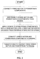
machine 100 is illustrated inFIG. 2 . The illustrated method involves using kinetic energy from thehybrid motor 118 to quickly speed up theengine 102 to an engine speed that exceeds the resonant frequency speed. The method involves operatively connecting thehybrid motor 118 to theengine 102 through the clutch 112, such that the hybrid motor can apply power to the engine when the clutch is engaged. When the clutch 112 is disengaged, thehybrid motor 118 is free to speed up without the burden of powering theengine 102. The illustrated method involves disengaging the clutch when thehybrid motor 118 speed is less than a predetermined hybrid motor speed that would power theengine 102 speed to exceed the resonant frequency engine speed. The method also involves engaging the clutch 112 when thehybrid motor 118 speed exceeds the predetermined hybrid motor speed. The kinetic energy from thehybrid motor 118 transferred to theengine 102 is sufficient to power the engine speed to exceed the resonant frequency engine speed. - In another method, illustrated in
FIG. 3 , thehybrid motor 118 is operatively connected to at least onepowertrain 101 component, such as thetransmission 114 or theauxiliary mechanisms 116. Thehybrid motor 118 is adapted to apply power to thepowertrain 101 components, which results in the components spinning and developingpowertrain 101 component kinetic energy. In this method, the clutch 112 disengages when thepowertrain 101 component kinetic energy is insufficient to transfer adequate energy to theengine 102 to power the engine to an engine speed that exceeds the resonant frequency engine speed. When thehybrid motor 118 speed reaches a predetermined hybrid motor speed, the clutch 112 engages, allowing thepowertrain 101 component kinetic energy to transfer to theengine 102. Thepowertrain 101 component kinetic energy can be determined from monitoring thehybrid motor 118 speed with theelectronic control module 124. Thepredetermined hybrid motor 118 speed is the speed that corresponds to thepowertrain 101 component kinetic energy that is sufficient to transfer enough power to theengine 102 so the engine speed exceeds the resonant frequency engine speed. Theelectronic control modules 124 of this disclosure may be of any conventional design having hardware and software configured to perform the calculations and send and receive appropriate signals to perform the engagement logic. Theelectronic control module 124 may include one or more controller units, and may be configured solely to perform the engagement strategy, or to perform the engagement strategy and other processes of themachine 100. The controller unit may be of any suitable construction, however in one example it comprises a digital processor system including a microprocessor circuit having data inputs and control outputs, operating in accordance with computer-readable instructions stored on a computer-readable medium. Typically, the processor will have associated therewith long-term (nonvolatile) memory for storing the program instructions, as well as short-term (volatile) memory for storing operands and results during (or resulting from) processing. - The arrangement disclosed herein has universal applicability in various other types of machines. The term "machine" may refer to any machine that performs some type of operation associated with an industry such as mining, construction, farming, transportation, or any other industry known in the art. For example, the machine may be an earth-moving machine, such as a wheel loader, excavator, dump truck, backhoe, motor grader, material handler or the like. Moreover, an implement may be connected to the machine. Such implements may be utilized for a variety of tasks, including, for example, loading, compacting, lifting, brushing, and include, for example, buckets, compactors, forked lifting devices, brushes, grapples, cutters, shears, blades, breakers/hammers, augers, and others.
- The industrial application of the methods for starting a machine that avoid effects of resonant frequencies as described herein should be readily appreciated from the foregoing discussion. The present disclosure may be applicable to any type of machine utilizing a powertrain that experiences resonant frequencies. It may be particularly useful in machines that include a hybrid motor that can apply power to components of the machine's powertrain.
- The disclosure, therefore, may be applicable to many different machines and environments. One exemplary machine suited to the disclosure is an off-highway truck. Off-highway trucks have large components that burden the truck's engine during startup with large inertial forces and parasitic load. These large inertial forces and parasitic load may result in damaging torque amplitudes experienced by the machine components at the powertrain's resonant frequency. Thus, a method for starting a machine that avoids the effects of resonant frequencies is readily applicable to an off-highway truck.
- Further, the methods above can be adapted to a large variety of machines. For example, other types of industrial machines, such as backhoe loaders, compactors, feller bunchers, forest machines, industrial loaders, wheel loaders and many other machines can benefit from the methods and systems described.
- It will be appreciated that the foregoing description provides examples of the disclosed system and technique. However, it is contemplated that other implementations of the disclosure may differ in detail from the foregoing examples. All references to the disclosure or examples thereof are intended to reference the particular example being discussed at that point and are not intended to imply any limitation as to the scope of the disclosure more generally. All language of distinction and disparagement with respect to certain features is intended to indicate a lack of preference for those features, but not to exclude such from the scope of the disclosure entirely unless otherwise indicated.
- The scope of protection is solely defined by the appended claims. Recitation of ranges of values herein are merely intended to serve as a shorthand method of referring individually to each separate value falling within the range, unless otherwise indicated herein, and each separate value is incorporated into the specification as if it were individually recited herein. All methods described herein can be performed in any suitable order unless otherwise indicated herein or otherwise clearly contradicted by context.
- Accordingly, this disclosure includes all modifications of the subject matter recited in the claims appended hereto as permitted by applicable law. Moreover, any combination of the above-described elements in all possible variations thereof is encompassed by the disclosure unless otherwise indicated herein or otherwise clearly contradicted by context.
Claims (6)
- A machine comprising:a clutch (112) adapted to engage and to disengage;an engine (102) operable at various engine speeds including a resonant frequency engine speed;an engine starter (104) operatively connected to the engine, the engine starter (104) being adapted to apply power to the engine;a hybrid motor (118), separate and in addition to the engine starter (104), the hybrid motor (118) being selectively operatively connected to the engine (102) through the clutch (112), the hybrid motor (118) being adapted to apply power to the engine (102) when the clutch (112) is engaged, and the hybrid motor (118) being adapted to not apply power to the engine (102) when the clutch (112) is disengaged, the hybrid motor (118) being operable at various hybrid motor speeds including a predetermined hybrid motor speed;at least one powertrain component, the at least one powertrain component being operatively connected to the hybrid motor (118) such that the hybrid motor (118) is adapted to apply power to the at least one powertrain component, wherein the at least one powertrain component is operatively connected to the engine (102) through the clutch (112) such that a powertrain component kinetic energy can be transferred to the engine (102) when the clutch (112) is engaged and the powertrain component kinetic energy cannot be transferred to the engine (102) when the clutch (112) is disengaged;an ignition switch (106) operatively associated with the hybrid motor (118), such that the ignition switch (106) is adapted to start the hybrid motor (118); andan electronic control module (124) configured to control the clutch (112) to disengage until such time as the hybrid motor speed exceeds the predetermined hybrid motor speed, and to engage to allow the hybrid motor (118) to apply power to the engine (102) at a time after the hybrid motor speed exceeds the predetermined hybrid motor speed;wherein the predetermined hybrid motor speed is sufficient to power the engine (102) to an engine speed that exceeds the resonant frequency engine speed;wherein the electronic control module (124) is operatively associated with the engine starter (104);wherein the electronic control module (124) is further configured to control the engine starter (104) to apply power to the engine (102) when the clutch (112) engages and at least until the engine speed exceeds the resonant frequency engine speed.
- The machine of claim 1 wherein:the predetermined hybrid motor speed is associated with a predetermined hybrid motor kinetic energy; andthe predetermined hybrid motor kinetic energy is sufficient to power the engine to a speed that exceeds the resonant frequency engine speed.
- The machine of either of claim 1 or 2, wherein the hybrid motor (118) is adapted to apply power to the at least one powertrain component when the ignition switch (106) is triggered.
- The machine of any of claims 1-3, wherein:the predetermined hybrid motor speed is associated with a predetermined powertrain component kinetic energy; andthe predetermined powertrain component kinetic energy is sufficient to transfer enough powertrain component kinetic energy to the engine (102) to power the engine (102) to a speed that exceeds the resonant frequency engine speed.
- The machine of any of claims 1-4, wherein the machine is an off-highway truck, an earth-moving machine, a wheel loader, an excavator, a dump truck, a backhoe, a motor grader, a material handler, a backhoe loader, a compactor, a feller buncher, a forest machine, or an industrial loader.
- A method of operating the machine of any of claims 1-5 comprising the steps of:disengaging the clutch (112) when the hybrid motor speed is less than the predetermined hybrid motor speed; andengaging the clutch (112) after the hybrid motor exceeds the predetermined hybrid motor speed.
Applications Claiming Priority (1)
| Application Number | Priority Date | Filing Date | Title |
|---|---|---|---|
| US13/545,578 US8939122B2 (en) | 2012-07-10 | 2012-07-10 | Engine starting strategy to avoid resonant frequency |
Publications (3)
| Publication Number | Publication Date |
|---|---|
| EP2685086A2 EP2685086A2 (en) | 2014-01-15 |
| EP2685086A3 EP2685086A3 (en) | 2017-03-15 |
| EP2685086B1 true EP2685086B1 (en) | 2021-06-09 |
Family
ID=48782117
Family Applications (1)
| Application Number | Title | Priority Date | Filing Date |
|---|---|---|---|
| EP13003204.8A Active EP2685086B1 (en) | 2012-07-10 | 2013-06-24 | Engine starting strategy to avoid resonant frequency |
Country Status (3)
| Country | Link |
|---|---|
| US (1) | US8939122B2 (en) |
| EP (1) | EP2685086B1 (en) |
| JP (1) | JP2014015205A (en) |
Families Citing this family (3)
| Publication number | Priority date | Publication date | Assignee | Title |
|---|---|---|---|---|
| US9150219B2 (en) * | 2014-02-21 | 2015-10-06 | Ford Global Technologies, Llc | Hybrid electric vehicle and method of starting engine |
| US9521497B2 (en) * | 2014-08-21 | 2016-12-13 | Google Technology Holdings LLC | Systems and methods for equalizing audio for playback on an electronic device |
| GB2560878B (en) * | 2017-02-24 | 2021-10-27 | Google Llc | A panel loudspeaker controller and a panel loudspeaker |
Citations (1)
| Publication number | Priority date | Publication date | Assignee | Title |
|---|---|---|---|---|
| JP2008179242A (en) * | 2007-01-24 | 2008-08-07 | Nissan Motor Co Ltd | Device for controlling mode switching during gear shift of hybrid car |
Family Cites Families (22)
| Publication number | Priority date | Publication date | Assignee | Title |
|---|---|---|---|---|
| DE19645943A1 (en) * | 1996-11-07 | 1998-05-14 | Bosch Gmbh Robert | Starter unit for an internal combustion engine |
| DE19745995A1 (en) * | 1997-03-11 | 1998-09-17 | Bosch Gmbh Robert | Gear-integrated electric machine for motor vehicle internal combustion engines and their control |
| DE19858992A1 (en) * | 1998-04-20 | 1999-10-21 | Bosch Gmbh Robert | Starter/drive unit for motor vehicle internal combustion engine with at least two starting methods |
| DE10030001A1 (en) * | 1999-12-28 | 2001-07-12 | Bosch Gmbh Robert | Starter control method for automobile i.c. engine with start-stop operation has starter drive train control evaluating operating parameters for providing required setting values for starter components |
| JP3571609B2 (en) * | 2000-03-29 | 2004-09-29 | ジヤトコ株式会社 | Parallel hybrid vehicle |
| JP3677733B2 (en) * | 2000-04-06 | 2005-08-03 | ジヤトコ株式会社 | Parallel hybrid vehicle |
| DE10030367C5 (en) * | 2000-06-21 | 2018-07-19 | Daimler Ag | Method for a pulse start of a piston engine |
| US6364807B1 (en) * | 2000-06-30 | 2002-04-02 | Ford Global Technologies, Inc. | Control strategy for a hybrid powertrain for an automotive vehicle |
| JP3815261B2 (en) | 2001-06-08 | 2006-08-30 | トヨタ自動車株式会社 | Start control device for internal combustion engine |
| JP2004340010A (en) * | 2003-05-15 | 2004-12-02 | Toyota Motor Corp | Engine starting system for vehicle |
| JP3858904B2 (en) * | 2004-03-11 | 2006-12-20 | 日産自動車株式会社 | Engagement method of engine clutch for hybrid transmission |
| US7351182B2 (en) * | 2004-10-27 | 2008-04-01 | Aisin Aw Co., Ltd. | Drive apparatus for hybrid vehicle and control method thereof |
| FR2890606B1 (en) | 2005-09-13 | 2008-11-07 | Renault Sas | METHOD FOR CONTROLLING A MOTOR POWERTRAIN COMPRISING TWO COOLING CIRCUITS |
| JP4358178B2 (en) * | 2005-10-26 | 2009-11-04 | トヨタ自動車株式会社 | Engine start control device |
| DE102006016138B4 (en) * | 2006-04-06 | 2014-11-20 | Robert Bosch Gmbh | Hybrid drive with emergency start option |
| DE102006054740A1 (en) * | 2006-11-21 | 2008-06-12 | Dr.Ing.H.C. F. Porsche Ag | Method and device for switching on an internal combustion engine in a hybrid vehicle drive |
| US8020652B2 (en) * | 2007-12-04 | 2011-09-20 | Ford Global Technologies, Llc | Generator power-based cold start strategy |
| KR100992781B1 (en) | 2007-12-13 | 2010-11-05 | 기아자동차주식회사 | System For Control Of Clutch Binding Of Hybrid Vehicle And Method Thereof |
| JP5187834B2 (en) | 2008-03-17 | 2013-04-24 | 現代自動車株式会社 | Clutch transmission torque control device for hybrid vehicle |
| DE102008041298A1 (en) * | 2008-08-18 | 2010-02-25 | Robert Bosch Gmbh | Device and method for starter support in a motor vehicle |
| US8192324B2 (en) | 2009-11-13 | 2012-06-05 | Ford Global Technologies, Llc | Vehicle and method for controlling engine start in a vehicle |
| WO2012108357A1 (en) * | 2011-02-08 | 2012-08-16 | 本田技研工業株式会社 | Driving device for hybrid vehicle |
-
2012
- 2012-07-10 US US13/545,578 patent/US8939122B2/en active Active
-
2013
- 2013-06-24 EP EP13003204.8A patent/EP2685086B1/en active Active
- 2013-07-09 JP JP2013143755A patent/JP2014015205A/en active Pending
Patent Citations (1)
| Publication number | Priority date | Publication date | Assignee | Title |
|---|---|---|---|---|
| JP2008179242A (en) * | 2007-01-24 | 2008-08-07 | Nissan Motor Co Ltd | Device for controlling mode switching during gear shift of hybrid car |
Also Published As
| Publication number | Publication date |
|---|---|
| JP2014015205A (en) | 2014-01-30 |
| EP2685086A3 (en) | 2017-03-15 |
| US20140014055A1 (en) | 2014-01-16 |
| US8939122B2 (en) | 2015-01-27 |
| EP2685086A2 (en) | 2014-01-15 |
Similar Documents
| Publication | Publication Date | Title |
|---|---|---|
| CN104828071B (en) | A kind of device and method for starting engine | |
| US8496561B2 (en) | Fluid coupling for a hybrid powertrain system | |
| CN1875186B (en) | Engine starting apparatus and method | |
| WO2012057024A1 (en) | Power transmission device | |
| RU2587470C2 (en) | Engine control method, control system and vehicle | |
| JP6539440B2 (en) | Engine start control device for hybrid working machine | |
| EP2685086B1 (en) | Engine starting strategy to avoid resonant frequency | |
| US8818662B2 (en) | Drive train of a mobile vehicle | |
| CN104641087B (en) | For estimating method of the engine in the speed in precalculated position | |
| WO2012057080A1 (en) | Power transmission device | |
| CN104294876A (en) | Hybrid construction machine | |
| US20190249615A1 (en) | Engine start controller for vehicle | |
| US9238458B2 (en) | Hybrid-electric vehicle engine starting method and system | |
| US8219273B2 (en) | Engine starting control for hybrid electric powertrains | |
| KR101565053B1 (en) | Shovel and method for controlling shovel | |
| EP2685085B1 (en) | Engine starting strategy to avoid resonant frequency | |
| US8954213B2 (en) | Engine starting strategy to avoid resonant frequency | |
| EP2685083A2 (en) | Engine starting strategy to avoid resonant frequency | |
| US10048660B2 (en) | Engine power management using current and steady state intake manifold pressure | |
| JP2012066786A (en) | Engine start control device of hybrid construction machine | |
| CN113389641A (en) | Cylinder cut-off mode of engine | |
| KR101449061B1 (en) | Outflux increasing control method of oil pump for Hybrid Electric Vehicle | |
| JP2004346834A (en) | Engine start controlling device | |
| US11859369B1 (en) | Spring preloaded lockup clutch | |
| WO2008009045A1 (en) | Multi-purpose drive system for a combustion engine |
Legal Events
| Date | Code | Title | Description |
|---|---|---|---|
| PUAI | Public reference made under article 153(3) epc to a published international application that has entered the european phase |
Free format text: ORIGINAL CODE: 0009012 |
|
| AK | Designated contracting states |
Kind code of ref document: A2 Designated state(s): AL AT BE BG CH CY CZ DE DK EE ES FI FR GB GR HR HU IE IS IT LI LT LU LV MC MK MT NL NO PL PT RO RS SE SI SK SM TR |
|
| AX | Request for extension of the european patent |
Extension state: BA ME |
|
| PUAL | Search report despatched |
Free format text: ORIGINAL CODE: 0009013 |
|
| AK | Designated contracting states |
Kind code of ref document: A3 Designated state(s): AL AT BE BG CH CY CZ DE DK EE ES FI FR GB GR HR HU IE IS IT LI LT LU LV MC MK MT NL NO PL PT RO RS SE SI SK SM TR |
|
| AX | Request for extension of the european patent |
Extension state: BA ME |
|
| RIC1 | Information provided on ipc code assigned before grant |
Ipc: F02N 5/04 20060101ALI20170203BHEP Ipc: F02N 11/08 20060101AFI20170203BHEP Ipc: F02N 15/02 20060101ALI20170203BHEP |
|
| STAA | Information on the status of an ep patent application or granted ep patent |
Free format text: STATUS: REQUEST FOR EXAMINATION WAS MADE |
|
| 17P | Request for examination filed |
Effective date: 20170915 |
|
| RBV | Designated contracting states (corrected) |
Designated state(s): AL AT BE BG CH CY CZ DE DK EE ES FI FR GB GR HR HU IE IS IT LI LT LU LV MC MK MT NL NO PL PT RO RS SE SI SK SM TR |
|
| STAA | Information on the status of an ep patent application or granted ep patent |
Free format text: STATUS: EXAMINATION IS IN PROGRESS |
|
| 17Q | First examination report despatched |
Effective date: 20190222 |
|
| STAA | Information on the status of an ep patent application or granted ep patent |
Free format text: STATUS: EXAMINATION IS IN PROGRESS |
|
| GRAP | Despatch of communication of intention to grant a patent |
Free format text: ORIGINAL CODE: EPIDOSNIGR1 |
|
| STAA | Information on the status of an ep patent application or granted ep patent |
Free format text: STATUS: GRANT OF PATENT IS INTENDED |
|
| INTG | Intention to grant announced |
Effective date: 20210208 |
|
| GRAS | Grant fee paid |
Free format text: ORIGINAL CODE: EPIDOSNIGR3 |
|
| GRAA | (expected) grant |
Free format text: ORIGINAL CODE: 0009210 |
|
| STAA | Information on the status of an ep patent application or granted ep patent |
Free format text: STATUS: THE PATENT HAS BEEN GRANTED |
|
| AK | Designated contracting states |
Kind code of ref document: B1 Designated state(s): AL AT BE BG CH CY CZ DE DK EE ES FI FR GB GR HR HU IE IS IT LI LT LU LV MC MK MT NL NO PL PT RO RS SE SI SK SM TR |
|
| REG | Reference to a national code |
Ref country code: GB Ref legal event code: FG4D |
|
| REG | Reference to a national code |
Ref country code: CH Ref legal event code: EP Ref country code: AT Ref legal event code: REF Ref document number: 1400713 Country of ref document: AT Kind code of ref document: T Effective date: 20210615 |
|
| REG | Reference to a national code |
Ref country code: DE Ref legal event code: R096 Ref document number: 602013077836 Country of ref document: DE |
|
| REG | Reference to a national code |
Ref country code: IE Ref legal event code: FG4D |
|
| REG | Reference to a national code |
Ref country code: LT Ref legal event code: MG9D |
|
| PG25 | Lapsed in a contracting state [announced via postgrant information from national office to epo] |
Ref country code: LT Free format text: LAPSE BECAUSE OF FAILURE TO SUBMIT A TRANSLATION OF THE DESCRIPTION OR TO PAY THE FEE WITHIN THE PRESCRIBED TIME-LIMIT Effective date: 20210609 Ref country code: FI Free format text: LAPSE BECAUSE OF FAILURE TO SUBMIT A TRANSLATION OF THE DESCRIPTION OR TO PAY THE FEE WITHIN THE PRESCRIBED TIME-LIMIT Effective date: 20210609 Ref country code: BG Free format text: LAPSE BECAUSE OF FAILURE TO SUBMIT A TRANSLATION OF THE DESCRIPTION OR TO PAY THE FEE WITHIN THE PRESCRIBED TIME-LIMIT Effective date: 20210909 Ref country code: HR Free format text: LAPSE BECAUSE OF FAILURE TO SUBMIT A TRANSLATION OF THE DESCRIPTION OR TO PAY THE FEE WITHIN THE PRESCRIBED TIME-LIMIT Effective date: 20210609 |
|
| REG | Reference to a national code |
Ref country code: AT Ref legal event code: MK05 Ref document number: 1400713 Country of ref document: AT Kind code of ref document: T Effective date: 20210609 |
|
| REG | Reference to a national code |
Ref country code: NL Ref legal event code: MP Effective date: 20210609 |
|
| PG25 | Lapsed in a contracting state [announced via postgrant information from national office to epo] |
Ref country code: SE Free format text: LAPSE BECAUSE OF FAILURE TO SUBMIT A TRANSLATION OF THE DESCRIPTION OR TO PAY THE FEE WITHIN THE PRESCRIBED TIME-LIMIT Effective date: 20210609 Ref country code: RS Free format text: LAPSE BECAUSE OF FAILURE TO SUBMIT A TRANSLATION OF THE DESCRIPTION OR TO PAY THE FEE WITHIN THE PRESCRIBED TIME-LIMIT Effective date: 20210609 Ref country code: LV Free format text: LAPSE BECAUSE OF FAILURE TO SUBMIT A TRANSLATION OF THE DESCRIPTION OR TO PAY THE FEE WITHIN THE PRESCRIBED TIME-LIMIT Effective date: 20210609 Ref country code: GR Free format text: LAPSE BECAUSE OF FAILURE TO SUBMIT A TRANSLATION OF THE DESCRIPTION OR TO PAY THE FEE WITHIN THE PRESCRIBED TIME-LIMIT Effective date: 20210910 Ref country code: NO Free format text: LAPSE BECAUSE OF FAILURE TO SUBMIT A TRANSLATION OF THE DESCRIPTION OR TO PAY THE FEE WITHIN THE PRESCRIBED TIME-LIMIT Effective date: 20210909 |
|
| PG25 | Lapsed in a contracting state [announced via postgrant information from national office to epo] |
Ref country code: EE Free format text: LAPSE BECAUSE OF FAILURE TO SUBMIT A TRANSLATION OF THE DESCRIPTION OR TO PAY THE FEE WITHIN THE PRESCRIBED TIME-LIMIT Effective date: 20210609 Ref country code: CZ Free format text: LAPSE BECAUSE OF FAILURE TO SUBMIT A TRANSLATION OF THE DESCRIPTION OR TO PAY THE FEE WITHIN THE PRESCRIBED TIME-LIMIT Effective date: 20210609 Ref country code: SK Free format text: LAPSE BECAUSE OF FAILURE TO SUBMIT A TRANSLATION OF THE DESCRIPTION OR TO PAY THE FEE WITHIN THE PRESCRIBED TIME-LIMIT Effective date: 20210609 Ref country code: SM Free format text: LAPSE BECAUSE OF FAILURE TO SUBMIT A TRANSLATION OF THE DESCRIPTION OR TO PAY THE FEE WITHIN THE PRESCRIBED TIME-LIMIT Effective date: 20210609 Ref country code: RO Free format text: LAPSE BECAUSE OF FAILURE TO SUBMIT A TRANSLATION OF THE DESCRIPTION OR TO PAY THE FEE WITHIN THE PRESCRIBED TIME-LIMIT Effective date: 20210609 Ref country code: PT Free format text: LAPSE BECAUSE OF FAILURE TO SUBMIT A TRANSLATION OF THE DESCRIPTION OR TO PAY THE FEE WITHIN THE PRESCRIBED TIME-LIMIT Effective date: 20211011 Ref country code: NL Free format text: LAPSE BECAUSE OF FAILURE TO SUBMIT A TRANSLATION OF THE DESCRIPTION OR TO PAY THE FEE WITHIN THE PRESCRIBED TIME-LIMIT Effective date: 20210609 Ref country code: ES Free format text: LAPSE BECAUSE OF FAILURE TO SUBMIT A TRANSLATION OF THE DESCRIPTION OR TO PAY THE FEE WITHIN THE PRESCRIBED TIME-LIMIT Effective date: 20210609 Ref country code: AT Free format text: LAPSE BECAUSE OF FAILURE TO SUBMIT A TRANSLATION OF THE DESCRIPTION OR TO PAY THE FEE WITHIN THE PRESCRIBED TIME-LIMIT Effective date: 20210609 |
|
| REG | Reference to a national code |
Ref country code: CH Ref legal event code: PL |
|
| PG25 | Lapsed in a contracting state [announced via postgrant information from national office to epo] |
Ref country code: PL Free format text: LAPSE BECAUSE OF FAILURE TO SUBMIT A TRANSLATION OF THE DESCRIPTION OR TO PAY THE FEE WITHIN THE PRESCRIBED TIME-LIMIT Effective date: 20210609 |
|
| REG | Reference to a national code |
Ref country code: BE Ref legal event code: MM Effective date: 20210630 |
|
| REG | Reference to a national code |
Ref country code: DE Ref legal event code: R097 Ref document number: 602013077836 Country of ref document: DE |
|
| PG25 | Lapsed in a contracting state [announced via postgrant information from national office to epo] |
Ref country code: MC Free format text: LAPSE BECAUSE OF FAILURE TO SUBMIT A TRANSLATION OF THE DESCRIPTION OR TO PAY THE FEE WITHIN THE PRESCRIBED TIME-LIMIT Effective date: 20210609 Ref country code: LU Free format text: LAPSE BECAUSE OF NON-PAYMENT OF DUE FEES Effective date: 20210624 |
|
| PLBE | No opposition filed within time limit |
Free format text: ORIGINAL CODE: 0009261 |
|
| STAA | Information on the status of an ep patent application or granted ep patent |
Free format text: STATUS: NO OPPOSITION FILED WITHIN TIME LIMIT |
|
| PG25 | Lapsed in a contracting state [announced via postgrant information from national office to epo] |
Ref country code: LI Free format text: LAPSE BECAUSE OF NON-PAYMENT OF DUE FEES Effective date: 20210630 Ref country code: IE Free format text: LAPSE BECAUSE OF NON-PAYMENT OF DUE FEES Effective date: 20210624 Ref country code: DK Free format text: LAPSE BECAUSE OF FAILURE TO SUBMIT A TRANSLATION OF THE DESCRIPTION OR TO PAY THE FEE WITHIN THE PRESCRIBED TIME-LIMIT Effective date: 20210609 Ref country code: CH Free format text: LAPSE BECAUSE OF NON-PAYMENT OF DUE FEES Effective date: 20210630 |
|
| 26N | No opposition filed |
Effective date: 20220310 |
|
| GBPC | Gb: european patent ceased through non-payment of renewal fee |
Effective date: 20210909 |
|
| PG25 | Lapsed in a contracting state [announced via postgrant information from national office to epo] |
Ref country code: AL Free format text: LAPSE BECAUSE OF FAILURE TO SUBMIT A TRANSLATION OF THE DESCRIPTION OR TO PAY THE FEE WITHIN THE PRESCRIBED TIME-LIMIT Effective date: 20210609 |
|
| PG25 | Lapsed in a contracting state [announced via postgrant information from national office to epo] |
Ref country code: IT Free format text: LAPSE BECAUSE OF FAILURE TO SUBMIT A TRANSLATION OF THE DESCRIPTION OR TO PAY THE FEE WITHIN THE PRESCRIBED TIME-LIMIT Effective date: 20210609 Ref country code: GB Free format text: LAPSE BECAUSE OF NON-PAYMENT OF DUE FEES Effective date: 20210909 Ref country code: FR Free format text: LAPSE BECAUSE OF NON-PAYMENT OF DUE FEES Effective date: 20210809 Ref country code: BE Free format text: LAPSE BECAUSE OF NON-PAYMENT OF DUE FEES Effective date: 20210630 |
|
| PG25 | Lapsed in a contracting state [announced via postgrant information from national office to epo] |
Ref country code: HU Free format text: LAPSE BECAUSE OF FAILURE TO SUBMIT A TRANSLATION OF THE DESCRIPTION OR TO PAY THE FEE WITHIN THE PRESCRIBED TIME-LIMIT; INVALID AB INITIO Effective date: 20130624 |
|
| P01 | Opt-out of the competence of the unified patent court (upc) registered |
Effective date: 20230517 |
|
| PG25 | Lapsed in a contracting state [announced via postgrant information from national office to epo] |
Ref country code: CY Free format text: LAPSE BECAUSE OF FAILURE TO SUBMIT A TRANSLATION OF THE DESCRIPTION OR TO PAY THE FEE WITHIN THE PRESCRIBED TIME-LIMIT Effective date: 20210609 |
|
| PGFP | Annual fee paid to national office [announced via postgrant information from national office to epo] |
Ref country code: DE Payment date: 20230523 Year of fee payment: 11 |