EP2685049A1 - Turbine blade - Google Patents
Turbine blade Download PDFInfo
- Publication number
- EP2685049A1 EP2685049A1 EP12757893.8A EP12757893A EP2685049A1 EP 2685049 A1 EP2685049 A1 EP 2685049A1 EP 12757893 A EP12757893 A EP 12757893A EP 2685049 A1 EP2685049 A1 EP 2685049A1
- Authority
- EP
- European Patent Office
- Prior art keywords
- portions
- cooling
- blade
- rows
- turbine blade
- Prior art date
- Legal status (The legal status is an assumption and is not a legal conclusion. Google has not performed a legal analysis and makes no representation as to the accuracy of the status listed.)
- Granted
Links
Images



Classifications
-
- F—MECHANICAL ENGINEERING; LIGHTING; HEATING; WEAPONS; BLASTING
- F01—MACHINES OR ENGINES IN GENERAL; ENGINE PLANTS IN GENERAL; STEAM ENGINES
- F01D—NON-POSITIVE DISPLACEMENT MACHINES OR ENGINES, e.g. STEAM TURBINES
- F01D5/00—Blades; Blade-carrying members; Heating, heat-insulating, cooling or antivibration means on the blades or the members
- F01D5/12—Blades
- F01D5/14—Form or construction
- F01D5/18—Hollow blades, i.e. blades with cooling or heating channels or cavities; Heating, heat-insulating or cooling means on blades
-
- F—MECHANICAL ENGINEERING; LIGHTING; HEATING; WEAPONS; BLASTING
- F01—MACHINES OR ENGINES IN GENERAL; ENGINE PLANTS IN GENERAL; STEAM ENGINES
- F01D—NON-POSITIVE DISPLACEMENT MACHINES OR ENGINES, e.g. STEAM TURBINES
- F01D5/00—Blades; Blade-carrying members; Heating, heat-insulating, cooling or antivibration means on the blades or the members
- F01D5/12—Blades
- F01D5/14—Form or construction
- F01D5/18—Hollow blades, i.e. blades with cooling or heating channels or cavities; Heating, heat-insulating or cooling means on blades
- F01D5/186—Film cooling
-
- F—MECHANICAL ENGINEERING; LIGHTING; HEATING; WEAPONS; BLASTING
- F01—MACHINES OR ENGINES IN GENERAL; ENGINE PLANTS IN GENERAL; STEAM ENGINES
- F01D—NON-POSITIVE DISPLACEMENT MACHINES OR ENGINES, e.g. STEAM TURBINES
- F01D5/00—Blades; Blade-carrying members; Heating, heat-insulating, cooling or antivibration means on the blades or the members
- F01D5/12—Blades
- F01D5/14—Form or construction
- F01D5/18—Hollow blades, i.e. blades with cooling or heating channels or cavities; Heating, heat-insulating or cooling means on blades
- F01D5/187—Convection cooling
-
- F—MECHANICAL ENGINEERING; LIGHTING; HEATING; WEAPONS; BLASTING
- F01—MACHINES OR ENGINES IN GENERAL; ENGINE PLANTS IN GENERAL; STEAM ENGINES
- F01D—NON-POSITIVE DISPLACEMENT MACHINES OR ENGINES, e.g. STEAM TURBINES
- F01D9/00—Stators
- F01D9/02—Nozzles; Nozzle boxes; Stator blades; Guide conduits, e.g. individual nozzles
-
- F—MECHANICAL ENGINEERING; LIGHTING; HEATING; WEAPONS; BLASTING
- F02—COMBUSTION ENGINES; HOT-GAS OR COMBUSTION-PRODUCT ENGINE PLANTS
- F02C—GAS-TURBINE PLANTS; AIR INTAKES FOR JET-PROPULSION PLANTS; CONTROLLING FUEL SUPPLY IN AIR-BREATHING JET-PROPULSION PLANTS
- F02C7/00—Features, components parts, details or accessories, not provided for in, or of interest apart form groups F02C1/00 - F02C6/00; Air intakes for jet-propulsion plants
- F02C7/12—Cooling of plants
- F02C7/16—Cooling of plants characterised by cooling medium
- F02C7/18—Cooling of plants characterised by cooling medium the medium being gaseous, e.g. air
-
- F—MECHANICAL ENGINEERING; LIGHTING; HEATING; WEAPONS; BLASTING
- F05—INDEXING SCHEMES RELATING TO ENGINES OR PUMPS IN VARIOUS SUBCLASSES OF CLASSES F01-F04
- F05D—INDEXING SCHEME FOR ASPECTS RELATING TO NON-POSITIVE-DISPLACEMENT MACHINES OR ENGINES, GAS-TURBINES OR JET-PROPULSION PLANTS
- F05D2240/00—Components
- F05D2240/20—Rotors
- F05D2240/30—Characteristics of rotor blades, i.e. of any element transforming dynamic fluid energy to or from rotational energy and being attached to a rotor
- F05D2240/304—Characteristics of rotor blades, i.e. of any element transforming dynamic fluid energy to or from rotational energy and being attached to a rotor related to the trailing edge of a rotor blade
-
- F—MECHANICAL ENGINEERING; LIGHTING; HEATING; WEAPONS; BLASTING
- F05—INDEXING SCHEMES RELATING TO ENGINES OR PUMPS IN VARIOUS SUBCLASSES OF CLASSES F01-F04
- F05D—INDEXING SCHEME FOR ASPECTS RELATING TO NON-POSITIVE-DISPLACEMENT MACHINES OR ENGINES, GAS-TURBINES OR JET-PROPULSION PLANTS
- F05D2260/00—Function
- F05D2260/20—Heat transfer, e.g. cooling
- F05D2260/202—Heat transfer, e.g. cooling by film cooling
-
- F—MECHANICAL ENGINEERING; LIGHTING; HEATING; WEAPONS; BLASTING
- F05—INDEXING SCHEMES RELATING TO ENGINES OR PUMPS IN VARIOUS SUBCLASSES OF CLASSES F01-F04
- F05D—INDEXING SCHEME FOR ASPECTS RELATING TO NON-POSITIVE-DISPLACEMENT MACHINES OR ENGINES, GAS-TURBINES OR JET-PROPULSION PLANTS
- F05D2260/00—Function
- F05D2260/20—Heat transfer, e.g. cooling
- F05D2260/221—Improvement of heat transfer
- F05D2260/2212—Improvement of heat transfer by creating turbulence
Definitions
- the present invention relates to a turbine blade.
- Priority is claimed on Japanese Patent Application No. 2011-054253, filed March 11, 2011 , the contents of which are incorporated herein by reference.
- Turbine blades that are provided in a turbine are generally exposed to high-temperature fluid bodies.
- the turbine blades provide in gas turbines are exposed to high-temperature combustion gas that has been discharged from a combustion chamber, they are exposed to an extremely high-temperature environment.
- a cooling gas such as cooling air is supplied to the interior of the turbine blades.
- an area around the rear edge of a turbine blade it is desirable for the thickness of an area around the rear edge of a turbine blade to be as thin as possible from the standpoint of the aerodynamic performance of the turbine. For this reason, in many cases it is difficult to form a flow path in the area around the rear edge of a turbine blade to enable the cooling gas to flow into the interior of the turbine blade. Namely, the area around the rear edge of a turbine blade can be said to be an area that is difficult to cool. Because of this, in, for example, Patent document 1 and Patent document 2, a technique is proposed in which the rear edge area is made thinner by forming notch portions in the ventral side of the rear edge area of a turbine blade, and film cooling is performed on the rear edge area by blowing cooling gas onto the ventral side surface that is exposed by these notch portions.
- the present invention was conceived in view of the above-described problems, and it is an object thereof to improve the cooling efficiency in an area around the rear edge of a turbine blade by suppressing any deterioration in the film cooling efficiency in the turbine blade, and by improving the heat transfer rate between the blade portion and the cooling gas.
- the present invention employs the following structure as a means of solving the above-described problems.
- a first aspect of the present invention is a turbine blade that is provided with a plurality of rows of cooling portions that have notch portions that discharge cooling gas that has been introduced into an internal portion of a blade portion onto a ventral side blade surface, and that are formed in rows that are stacked in a direction between the blade front edge and the blade rear edge, and that includes: turbulence promoting cooling portions that are provided in the row located furthest to the downstream side from among the plurality of rows, and that have turbulence promoting devices in areas exposed by the notch portions; and film cooling portions that are provided in at least one of other rows from among the plurality of rows, and that form a film cooling layer in the areas exposed by the notch portions.
- a second aspect of the present invention is the turbine blade according to the first or second aspects wherein, in at least one of the plurality of rows, the plurality of cooling portions are placed discretely from each other in the height direction of the blade portion.
- a third aspect of the present invention is the turbine blade according to any of the first through third aspects wherein, in at least one of the plurality of rows, the cooling portions are provided continuously in an elongated shape in the height direction of the blade portion.
- a fourth aspect of the present invention is the turbine blade according to any of the first through fourth aspects wherein the turbulence promoting device is formed by a plurality of pin portions that stand upright in the areas exposed by the notch portions.
- a fifth aspect of the present invention is the turbine blade according to any of the first through fourth aspects wherein the turbulence promoting device is formed by a plurality of step portions that stand upright in the areas exposed by the notch portions and that are stacked in rows in the flow direction of the cooling gas.
- a sixth aspect of the present invention is the turbine blade according to any of the first through fourth aspects wherein the turbulence promoting device is formed by a plurality of dimple portions that are formed in the areas exposed by the notch portions.
- a plurality of rows of cooling portions having notch portions are provided in rows that are stacked in a direction from the front edge of a blade to the rear edge of the blade.
- the row located furthest to the downstream side from among this plurality of rows of cooling portions forms a turbulence promoting cooling portion that is provided with turbulence promoting devices and cools by means of turbulence.
- All of the other rows form film cooling portions that form a film cooling layer.
- FIG. 1 is a perspective view of a turbine blade 1 of the present embodiment.
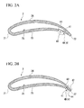
- FIGS. 2A and 2B are cross-sectional views of the turbine blade 1
- FIG. 2A is a cross-sectional view taken along a line A-A in FIG. 1
- FIG. 2B is a cross-sectional view taken along a line B-B in FIG. 1 .
- the turbine blade 1 of the present embodiment is provided with a blade portion 2, a root portion 3, and cooling portions 4.
- the blade portion 2 is set in a blade shape having a front edge 21 (i.e., a blade front edge), a rear edge 22 (i.e., a blade rear edge), a ventral side blade surface 23 (i.e., a blade belly), and a rear side blade surface 24.
- a front edge 21 i.e., a blade front edge
- a rear edge 22 i.e., a blade rear edge
- a ventral side blade surface 23 i.e., a blade belly
- a rear side blade surface 24 i.e., a blade belly
- an internal portion 25 i.e., a blade interior portion
- This blade portion 2 is positioned with the front edge 21 facing towards the upstream side of the fluid body.
- a flow in which the fluid body flows from the front edge 21 towards the rear edge 22 is formed on the surfaces of the ventral side blade surface 23 and the rear side blade surface 24 of the blade portion 2.
- a flow from the front edge 21 towards the rear edge 22 along the surfaces of the ventral side blade surface 23 and the rear side blade surface 24 is referred to as a main flow.
- the root portion 3 supports the blade portion 2, and is fixed to a turbine disk. Note that the root portion 3 has an internal flow path (not shown). Cooling gas is supplied to the internal portion 25 of the blade portion 2 through this internal flow path in the root portion 3.
- the cooling portions 4 discharge the cooling gas introduced into the internal portion 25 of the blade portion 2 onto the ventral side blade surface 23 side of the rear edge 22 side, and cool the rear edge area including the rear edge 22.
- These cooling portions 4 have notch portions 41 that are formed on the ventral side blade surface 23 side, and these notch portions 41 form slots 42.
- the cooling portions 4 have through holes 43 that are provided in the wall portion on the front edge 21 side of the slot 42, and that penetrate into the interior portion 25 of the blade portion 2. These through holes 43 discharge cooling gas into the notch portions 41.
- the cooling portions 4 of the turbine blade 1 of the present embodiment have notch portions 41 that discharge the cooling gas introduced into the internal portion 25 of the blade portion 2 onto the ventral side blade surface 23 side.
- the turbine blade 1 of the present embodiment is provided with two rows (i.e., a plurality of rows) of the cooling portions 4 that are stacked in a direction from the front edge 21 towards the rear edge 22.
- Each of these rows is formed by a plurality of the cooling portions 4 that are placed discretely from each other in the height direction of the blade portion 2 (i.e., in the top-bottom direction of the sheet of paper on which FIG. 1 is shown) and at equal distances from each other.
- the cooling portions 4 that form the row on the front edge 21 side, and the cooling portions 4 that form the row on the rear edge 22 side are offset from each other in the height direction of the blade portion 2.
- the cooling portions 4 are arranged in a zigzag pattern.
- the cooling portions 4 that form the row on the front edge 21 side make up film cooling portions 4A, while the cooling portions 4 that form the row on the rear edge 22 side make up film cooling portions 4B.
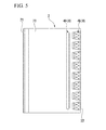
- FIG. 3A is an enlarged perspective view of a film cooling portion 4A.
- the film forming portion 4A is provided with a flat area R that is exposed by the notch portion 41.
- This film cooling portion 4A forms a film cooling layer using the cooling gas that is discharged from the through hole 43, and thereby performs film cooling.
- the film cooling portion 4A forms a film cooling layer in the area R that is exposed by the notch portion 41, and is thereby able to perform film cooling. Namely, the area around the rear edge of the blade portion 2 is able to be cooled by this structure.
- FIG. 3B is an enlarged perspective view of a film turbulence promoting cooling portion 4B.
- the turbulence promoting cooling portion 4B is provided with a plurality of pin portions 44 (i.e., turbulence promoting devices) that stand upright on the flat area R that is exposed by the notch portions 41.
- This turbulence promoting cooling portion 4B promotes turbulence as a result of the laminar flow expelled from the through hole 43 colliding with the plurality of pin portions 44. Namely, using this turbulence, it is possible to promote a convective heat transfer between the film air and the blade portion.
- FIG. 3B is an enlarged perspective view of a film turbulence promoting cooling portion 4B.
- the turbulence promoting cooling portion 4B is provided with a plurality of pin portions 44 (i.e., turbulence promoting devices) that stand upright on the flat area R that is exposed by the notch portions 41.
- the plurality of pin portions 44 are arranged in a zigzag pattern on the area R.
- the height of each pin portion 44 is set such that the pin portions 44 do not protrude above the surface of the ventral side blade surface 23 in order to avoid any collision with the aforementioned main flow. Note that, as is shown in FIG. 3B , in the present embodiment all of the pin portions 44 are set at the same height, however, it is not essential for the height of the pin portions 44 to be standardized.
- the plurality of rows of cooling portions 4 that have the notch portions 41 are arranged so as to form rows that are stacked from the front edge 21 towards the rear edge 22.
- the row from among the plurality of rows of cooling portions 4 that is located on the rear edge 22 side forms the turbulence promoting cooling portions 4B, while the row on the front edge 21 side forms the film cooling portions 4A. Because of this, according to the turbine blade 1 of the present embodiment, a convective heat transfer is promoted by the turbulence promoting cooling portions 4B, and a film cooling layer is formed by the film cooling portions 4A.
- the convective heat transfer that is generated between the film cooling gas whose temperature is lower than that of the main flow gas and the blade portion is promoted by the turbulence promoting cooling portion, rear edge portions of a blade portion can be cooled efficiently. Accordingly, according to the present invention, by providing the notch portions that form the film cooling layer separately from the notch portions that have a structure that promotes the transfer of heat, it is possible to suppress any reduction in the film cooling efficiency, and to improve the heat transfer rate between the blade portions and the cooling gas. As a result, the cooling efficiency of the area around the rear edge of a blade portion can be improved.
- the cooling portions 4 that form the row furthest to the rear edge 22 side form the turbulence promoting cooling portions 4B.
- the rear side blade surface of the rear edge side of the blade portion is where the temperature of the blade surface is most easily increased, and it is necessary to strengthen the cooling in this region. Namely, by providing notch portions in the wall surface of the side of the blade portion having this region that is cooled (i.e., the blade belly side), it is possible to achieve a heat transfer in this region at a high heat transfer rate with cooling gas at the lowest possible temperature.
- the effects of this turbulence on the downstream side of the flow can be reduced. Namely, it is possible to prevent any deterioration in the film cooling efficiency and to improve the heat transfer rate between the blade portion and the cooling gas.
- a structure is employed in which turbulence is created by the pin portions 44. Because of this, turbulence can be created by means of a simple structure.
- step portions 45 i.e., turbulence promoting devices
- the cooling gas discharged from the through holes 43 is able to collide with the step portions 45 so that turbulence is promoted by this structure as well. Namely, turbulence can be promoted by means of a simple structure.
- the plurality of cooling portions 4 that make up a row are placed discretely from each other in the height direction of the blade portion. As a consequence, it is possible to leave a thick area of the blade portion between cooling portions 4 so that the strength of the turbine blade 1 remains unimpaired.
- cooling portion 4 i.e., the cooling portion 4A in FIG. 5
- the cooling portion 4A it is possible to cool an even broader range in the height direction of the blade portion.
- the cooling portion 4 is formed in an elongated shape, then the surface area of the apertures of the through holes also increases.
- the flow rate of cooling gas that is discharged from a row that is formed by this cooling portion 4 that is provided continuously in an elongated shape will be greater than the flow rate of cooling gas discharged from a row that is formed by cooling portions 4 that are arranged discretely. Because of this, if the cooling portion 4 is formed in an elongated shape, it is preferable for the surface area of the apertures of the through holes in the cooling portion 4 that is provided continuously in an elongated shape to be narrowed down, so that sufficient cooling gas can be discharged from the cooling portions 4 that are arranged discretely.
- the typical view of a turbine blade in FIG. 1 shows a moving blade.
- the present structure can also be applied to a stationary blade.
- two rows of cooling portions 4 are provided so as to form rows that are stacked in the flow direction of the main flow.
- the present invention is not limited to this and it is also possible to provide the plurality of rows of cooling portions 4 in three or more rows in the flow direction of the main flow.
- those cooling portions in the row located furthest to the downstream side form the turbulence promoting cooling portions 4B, while the cooling portions in at least one of the other rows form the film cooling portions 4A.
- the cooling portions 4 are arranged in a zigzag pattern.
- the present invention is not limited to this and it is also possible for the cooling portions 4 to be arranged in a lattice configuration.
- the through holes 43 are not formed in the turbulence promoting cooling portions 4B.
- notch portions that form a film separately from notch portions that have a structure that promotes the transfer of heat, it is possible to suppress any reduction in the film cooling efficiency, and to improve the heat transfer rate between the blade portions and the cooling gas. As a result, the cooling efficiency of the area around the rear edge of a turbine blade can be improved.
Landscapes
- Engineering & Computer Science (AREA)
- Mechanical Engineering (AREA)
- General Engineering & Computer Science (AREA)
- Chemical & Material Sciences (AREA)
- Combustion & Propulsion (AREA)
- Turbine Rotor Nozzle Sealing (AREA)
Abstract
Description
- The present invention relates to a turbine blade. Priority is claimed on Japanese Patent Application No.
2011-054253, filed March 11, 2011 - Turbine blades that are provided in a turbine are generally exposed to high-temperature fluid bodies. In particular, because the turbine blades provide in gas turbines are exposed to high-temperature combustion gas that has been discharged from a combustion chamber, they are exposed to an extremely high-temperature environment. In order to increase the durability of turbine blades that are exposed to this type of high-temperature environment, in some cases a cooling gas such as cooling air is supplied to the interior of the turbine blades. By supplying cooling gas to the interior of the blades in this manner, it is possible to suppress any rise in the temperature of the turbine blades, and to thereby improve the durability of the turbine blades.
- It is desirable for the thickness of an area around the rear edge of a turbine blade to be as thin as possible from the standpoint of the aerodynamic performance of the turbine. For this reason, in many cases it is difficult to form a flow path in the area around the rear edge of a turbine blade to enable the cooling gas to flow into the interior of the turbine blade. Namely, the area around the rear edge of a turbine blade can be said to be an area that is difficult to cool. Because of this, in, for example, Patent document 1 and
Patent document 2, a technique is proposed in which the rear edge area is made thinner by forming notch portions in the ventral side of the rear edge area of a turbine blade, and film cooling is performed on the rear edge area by blowing cooling gas onto the ventral side surface that is exposed by these notch portions. -
- [Patent document 1] Japanese Unexamined Patent Application, First Publication No.
2003-56301 - [Patent document 2] United States Patent No.
5215431 - However, in the techniques proposed in Patent document 1 and
Patent document 2, it is difficult to adequately cool the area around the rear edge of a turbine blade, and further improvements in the cooling efficiency in the area around the rear edge portion of a turbine blade are desired. For example, it is possible to increase the heat transfer rate between the blade portion and the cooling gas by generating turbulence in the flow of the cooling gas discharged from the notch portions. However, if turbulence is generated in the flow of this cooling gas, then this has the disadvantage that the cooling gas gets immediately mixed into the main flow that is flowing over the surface of the blade portions, so that the temperature of the cooling gas that is serving as a refrigerant is raised. Namely, if the turbulence in the cooling gas is promoted more than is necessary, then the mixing of the film cooling layer with the main flow gas is accelerated, and the efficiency of the film cooling is deteriorated. - The present invention was conceived in view of the above-described problems, and it is an object thereof to improve the cooling efficiency in an area around the rear edge of a turbine blade by suppressing any deterioration in the film cooling efficiency in the turbine blade, and by improving the heat transfer rate between the blade portion and the cooling gas.
- The present invention employs the following structure as a means of solving the above-described problems.
- A first aspect of the present invention is a turbine blade that is provided with a plurality of rows of cooling portions that have notch portions that discharge cooling gas that has been introduced into an internal portion of a blade portion onto a ventral side blade surface, and that are formed in rows that are stacked in a direction between the blade front edge and the blade rear edge, and that includes: turbulence promoting cooling portions that are provided in the row located furthest to the downstream side from among the plurality of rows, and that have turbulence promoting devices in areas exposed by the notch portions; and film cooling portions that are provided in at least one of other rows from among the plurality of rows, and that form a film cooling layer in the areas exposed by the notch portions.
- A second aspect of the present invention is the turbine blade according to the first or second aspects wherein, in at least one of the plurality of rows, the plurality of cooling portions are placed discretely from each other in the height direction of the blade portion.
- A third aspect of the present invention is the turbine blade according to any of the first through third aspects wherein, in at least one of the plurality of rows, the cooling portions are provided continuously in an elongated shape in the height direction of the blade portion.
- A fourth aspect of the present invention is the turbine blade according to any of the first through fourth aspects wherein the turbulence promoting device is formed by a plurality of pin portions that stand upright in the areas exposed by the notch portions.
- A fifth aspect of the present invention is the turbine blade according to any of the first through fourth aspects wherein the turbulence promoting device is formed by a plurality of step portions that stand upright in the areas exposed by the notch portions and that are stacked in rows in the flow direction of the cooling gas.
- A sixth aspect of the present invention is the turbine blade according to any of the first through fourth aspects wherein the turbulence promoting device is formed by a plurality of dimple portions that are formed in the areas exposed by the notch portions.
- In the present invention, a plurality of rows of cooling portions having notch portions are provided in rows that are stacked in a direction from the front edge of a blade to the rear edge of the blade. The row located furthest to the downstream side from among this plurality of rows of cooling portions forms a turbulence promoting cooling portion that is provided with turbulence promoting devices and cools by means of turbulence. All of the other rows form film cooling portions that form a film cooling layer. As a consequence, according to the present invention, the turbulence of the cooling gas is promoted by the turbulence promoting cooling portions so that a convective heat transfer is promoted in the turbulence promoting cooling portions, and a film cooling layer is formed by the cooling gas flowing out from the film cooling portions. This enables film cooling to be performed. Namely, according to the present invention, in rear edge areas of the blade portions, a convective heat transfer with the film cooling gas whose temperature is lower than that of the main flow gas is promoted by the turbulence promoting cooling portions. As a result, rear edge portions of a blade portion can be cooled efficiently. Accordingly, according to the present invention, by providing notch portions that form a film separately from notch portions that have a structure that promotes the transfer of heat, it is possible to suppress any reduction in the film cooling efficiency, and to improve the heat transfer rate between the blade portions and the cooling gas. As a result, the cooling efficiency of the area around the rear edge of a blade portion can be improved.
-
- [
FIG. 1] FIG. 1 is a perspective view of a turbine blade according to an embodiment of the present invention. - [
FIG. 2A] FIG. 2A is a cross-sectional view of a turbine blade according to an embodiment of the present invention. - [
FIG. 2B] FIG. 2B is a cross-sectional view of a turbine blade according to an embodiment of the present invention. - [
FIG. 3A] FIG. 3A is a perspective view showing in enlargement principal portions of a turbine blade according to an embodiment of the present invention. - [
FIG. 3B] FIG. 3B is a perspective view showing in enlargement principal portions of a turbine blade according to an embodiment of the present invention. - [
FIG. 4A] FIG. 4A is an enlarged perspective view showing a variant example of a turbine blade according to an embodiment of the present invention. - [
FIG. 4B] FIG. 4B is an enlarged perspective view showing a variant example of a turbine blade according to an embodiment of the present invention. - [
FIG. 5] FIG. 5 is a plan view showing a variant example of a turbine blade according to an embodiment of the present invention. - Hereinafter, an embodiment of a turbine blade according to the present invention will be described with reference made to the drawings. Note that in the drawings the scale of each component has been suitably altered in order to make each component a recognizable size.
-
FIG. 1 is a perspective view of a turbine blade 1 of the present embodiment.
FIGS. 2A and 2B are cross-sectional views of the turbine blade 1,FIG. 2A is a cross-sectional view taken along a line A-A inFIG. 1 , andFIG. 2B is a cross-sectional view taken along a line B-B inFIG. 1 . As is shown inFIG. 1 , the turbine blade 1 of the present embodiment is provided with ablade portion 2, a root portion 3, andcooling portions 4. - As is shown in
FIGS. 2A and 2B , theblade portion 2 is set in a blade shape having a front edge 21 (i.e., a blade front edge), a rear edge 22 (i.e., a blade rear edge), a ventral side blade surface 23 (i.e., a blade belly), and a rearside blade surface 24. In addition, an internal portion 25 (i.e., a blade interior portion) of theblade portion 2 is provided with a hollow portion into which a cooling gas can be introduced. Thisblade portion 2 is positioned with thefront edge 21 facing towards the upstream side of the fluid body. As a result, a flow in which the fluid body flows from thefront edge 21 towards therear edge 22 is formed on the surfaces of the ventralside blade surface 23 and the rearside blade surface 24 of theblade portion 2. Note that in the following description, a flow from thefront edge 21 towards therear edge 22 along the surfaces of the ventralside blade surface 23 and the rearside blade surface 24 is referred to as a main flow. - The root portion 3 supports the
blade portion 2, and is fixed to a turbine disk. Note that the root portion 3 has an internal flow path (not shown). Cooling gas is supplied to theinternal portion 25 of theblade portion 2 through this internal flow path in the root portion 3. - The cooling
portions 4 discharge the cooling gas introduced into theinternal portion 25 of theblade portion 2 onto the ventralside blade surface 23 side of therear edge 22 side, and cool the rear edge area including therear edge 22. These coolingportions 4 havenotch portions 41 that are formed on the ventralside blade surface 23 side, and thesenotch portions 41form slots 42. Moreover, the coolingportions 4 have throughholes 43 that are provided in the wall portion on thefront edge 21 side of theslot 42, and that penetrate into theinterior portion 25 of theblade portion 2. These throughholes 43 discharge cooling gas into thenotch portions 41. In this manner, the coolingportions 4 of the turbine blade 1 of the present embodiment havenotch portions 41 that discharge the cooling gas introduced into theinternal portion 25 of theblade portion 2 onto the ventralside blade surface 23 side. - Moreover, as is shown in
FIG. 1 , the turbine blade 1 of the present embodiment is provided with two rows (i.e., a plurality of rows) of thecooling portions 4 that are stacked in a direction from thefront edge 21 towards therear edge 22. Each of these rows is formed by a plurality of thecooling portions 4 that are placed discretely from each other in the height direction of the blade portion 2 (i.e., in the top-bottom direction of the sheet of paper on whichFIG. 1 is shown) and at equal distances from each other. Moreover, as is shown inFIG. 1 , the coolingportions 4 that form the row on thefront edge 21 side, and thecooling portions 4 that form the row on therear edge 22 side are offset from each other in the height direction of theblade portion 2. As a result, the coolingportions 4 are arranged in a zigzag pattern. - In addition, in the turbine blade 1 of the present embodiment, the cooling
portions 4 that form the row on thefront edge 21 side make upfilm cooling portions 4A, while thecooling portions 4 that form the row on therear edge 22 side make upfilm cooling portions 4B. -
FIG. 3A is an enlarged perspective view of afilm cooling portion 4A. As is shown inFIG. 3A , thefilm forming portion 4A is provided with a flat area R that is exposed by thenotch portion 41. Thisfilm cooling portion 4A forms a film cooling layer using the cooling gas that is discharged from the throughhole 43, and thereby performs film cooling. In other words, thefilm cooling portion 4A forms a film cooling layer in the area R that is exposed by thenotch portion 41, and is thereby able to perform film cooling. Namely, the area around the rear edge of theblade portion 2 is able to be cooled by this structure. -
FIG. 3B is an enlarged perspective view of a film turbulence promotingcooling portion 4B. As is shown inFIG. 3B , the turbulence promotingcooling portion 4B is provided with a plurality of pin portions 44 (i.e., turbulence promoting devices) that stand upright on the flat area R that is exposed by thenotch portions 41. This turbulence promotingcooling portion 4B promotes turbulence as a result of the laminar flow expelled from the throughhole 43 colliding with the plurality ofpin portions 44. Namely, using this turbulence, it is possible to promote a convective heat transfer between the film air and the blade portion. Moreover, as is shown inFIG. 3B , the plurality ofpin portions 44 are arranged in a zigzag pattern on the area R. The height of eachpin portion 44 is set such that thepin portions 44 do not protrude above the surface of the ventralside blade surface 23 in order to avoid any collision with the aforementioned main flow. Note that, as is shown inFIG. 3B , in the present embodiment all of thepin portions 44 are set at the same height, however, it is not essential for the height of thepin portions 44 to be standardized. - In the turbine blade 1 of the present embodiment that is constructed in the above-described manner, the plurality of rows of cooling
portions 4 that have thenotch portions 41 are arranged so as to form rows that are stacked from thefront edge 21 towards therear edge 22. In addition, the row from among the plurality of rows of coolingportions 4 that is located on therear edge 22 side forms the turbulence promotingcooling portions 4B, while the row on thefront edge 21 side forms thefilm cooling portions 4A. Because of this, according to the turbine blade 1 of the present embodiment, a convective heat transfer is promoted by the turbulence promotingcooling portions 4B, and a film cooling layer is formed by thefilm cooling portions 4A. Namely, because the convective heat transfer that is generated between the film cooling gas whose temperature is lower than that of the main flow gas and the blade portion is promoted by the turbulence promoting cooling portion, rear edge portions of a blade portion can be cooled efficiently. Accordingly, according to the present invention, by providing the notch portions that form the film cooling layer separately from the notch portions that have a structure that promotes the transfer of heat, it is possible to suppress any reduction in the film cooling efficiency, and to improve the heat transfer rate between the blade portions and the cooling gas. As a result, the cooling efficiency of the area around the rear edge of a blade portion can be improved. - Moreover, in the turbine blade 1 of the present embodiment, the cooling
portions 4 that form the row furthest to therear edge 22 side form the turbulence promotingcooling portions 4B. Normally, the rear side blade surface of the rear edge side of the blade portion is where the temperature of the blade surface is most easily increased, and it is necessary to strengthen the cooling in this region. Namely, by providing notch portions in the wall surface of the side of the blade portion having this region that is cooled (i.e., the blade belly side), it is possible to achieve a heat transfer in this region at a high heat transfer rate with cooling gas at the lowest possible temperature. Furthermore, as in the turbine blade 1 of the present embodiment, as a result of thecooling portions 4 that form the row furthest to therear edge 22 side forming the turbulence promotingcooling portions 4B, the effects of this turbulence on the downstream side of the flow can be reduced. Namely, it is possible to prevent any deterioration in the film cooling efficiency and to improve the heat transfer rate between the blade portion and the cooling gas. - Moreover, in the turbine blade 1 of the present embodiment, a structure is employed in which turbulence is created by the
pin portions 44. Because of this, turbulence can be created by means of a simple structure. - Note that, as is shown, for example, in
FIG. 4A , instead of thepin portions 44 it is possible to provide a plurality of step portions 45 (i.e., turbulence promoting devices) that stand upright on the flat area R that is exposed by thenotch portions 41, and that are arranged in the flow direction of the cooling gas. When this plurality ofstep portions 45 are used, the cooling gas discharged from the throughholes 43 is able to collide with thestep portions 45 so that turbulence is promoted by this structure as well. Namely, turbulence can be promoted by means of a simple structure. - Moreover, as is shown, for example, in
FIG. 4B , instead of thepin portions 44 it is possible to provide a plurality of dimple portions 46 (i.e., turbulence promoting devices) that are formed in the area that is exposed by thenotch portions 41. When this plurality ofdimple portions 46 are used, the cooling gas discharged from the throughholes 43 flows into thedimple portions 46 so that turbulence is generated by this structure as well. Namely, turbulence can be promoted by means of a simple structure. - Moreover, in the turbine blade 1 of the present embodiment, the plurality of cooling
portions 4 that make up a row are placed discretely from each other in the height direction of the blade portion. As a consequence, it is possible to leave a thick area of the blade portion betweencooling portions 4 so that the strength of the turbine blade 1 remains unimpaired. - Note that as is shown, for example, in
FIG. 5 , it is also possible to provide a cooling portion 4 (i.e., the coolingportion 4A inFIG. 5 ) that is provided continuously in an elongated shape in the height direction of the blade portion. By employing this type ofcooling portion 4, it is possible to cool an even broader range in the height direction of the blade portion. However, if the coolingportion 4 is formed in an elongated shape, then the surface area of the apertures of the through holes also increases. Namely, there is a possibility that the flow rate of cooling gas that is discharged from a row that is formed by this coolingportion 4 that is provided continuously in an elongated shape will be greater than the flow rate of cooling gas discharged from a row that is formed by coolingportions 4 that are arranged discretely. Because of this, if the coolingportion 4 is formed in an elongated shape, it is preferable for the surface area of the apertures of the through holes in the coolingportion 4 that is provided continuously in an elongated shape to be narrowed down, so that sufficient cooling gas can be discharged from the coolingportions 4 that are arranged discretely. - While preferred embodiments of the invention have been described and illustrated above, it should be understood that these are exemplary of the invention and are not to be considered as limiting. Combinations or the like of the respective members shown in the aforementioned examples, and can be variously changed in a scope of not depending from the gist of the present invention based on the design request or the like.
- For example, the typical view of a turbine blade in
FIG. 1 shows a moving blade. However, the present structure can also be applied to a stationary blade. - Moreover, in the turbine blade 1 of the present embodiment, two rows of cooling
portions 4 are provided so as to form rows that are stacked in the flow direction of the main flow. However, the present invention is not limited to this and it is also possible to provide the plurality of rows of coolingportions 4 in three or more rows in the flow direction of the main flow. In this case, of the plurality of rows of coolingportions 4 of the present invention, those cooling portions in the row located furthest to the downstream side form the turbulence promotingcooling portions 4B, while the cooling portions in at least one of the other rows form thefilm cooling portions 4A. - Moreover, in the turbine blade 1 of the present embodiment, the cooling
portions 4 are arranged in a zigzag pattern. However, the present invention is not limited to this and it is also possible for thecooling portions 4 to be arranged in a lattice configuration. Moreover, it is also possible that the throughholes 43 are not formed in the turbulence promotingcooling portions 4B. - According to the present invention, by providing notch portions that form a film separately from notch portions that have a structure that promotes the transfer of heat, it is possible to suppress any reduction in the film cooling efficiency, and to improve the heat transfer rate between the blade portions and the cooling gas. As a result, the cooling efficiency of the area around the rear edge of a turbine blade can be improved.
-
- 1
- Turbine blade
- 2
- Blade portion
- 21
- Front edge (Blade front edge)
- 22
- Rear edge (Blade rear edge)
- 23
- Ventral side blade surface (Ventral side)
- 24
- Rear side blade surface (Rear side)
- 25
- Internal portion (Internal portion of the blade portion)
- 4
- Cooling portion
- 4A
- Film cooling portion (Cooling portion)
- 4B
- Turbulence promoting cooling portion (Cooling portion)
- 41
- Notch portion
- 42
- Slot
- 43
- Through hole
- 44
- Pin portion (Turbulence promoting device)
- 45
- Step portion (Turbulence promoting device)
- 46
- Dimple portion (Turbulence promoting device)
Claims (6)
- A turbine blade that is provided with a plurality of rows of cooling portions that have notch portions that discharge cooling gas that has been introduced into an internal portion of a blade portion onto a ventral side blade surface, and that are formed in rows that are stacked in a direction between the blade front edge and the blade rear edge, comprising:turbulence promoting cooling portions that are provided in the row located closest to the downstream side from among the plurality of rows, and that have turbulence promoting devices in areas exposed by the notch portions; andfilm cooling portions that are provided in at least one of other rows from among the plurality of rows, and that form a film cooling layer in the areas exposed by the notch portions.
- The turbine blade according to claim 1, wherein, in at least one of the plurality of rows, the plurality of cooling portions are placed discretely from each other in the height direction of the blade portion.
- The turbine blade according to claim 1, wherein, in at least one of the plurality of rows, the cooling portions are provided continuously in an elongated shape in the height direction of the blade portion.
- The turbine blade according to claim 1, wherein the turbulence promoting device is formed by a plurality of pin portions that stand upright in the areas exposed by the notch portions.
- The turbine blade according to claim 1, wherein the turbulence promoting device is formed by a plurality of step portions that stand upright in the areas exposed by the notch portions and that are stacked in rows in the flow direction of the cooling gas.
- The turbine blade according to claim 1, wherein the turbulence promoting device is formed by a plurality of dimple portions that are formed in the areas exposed by the notch portions.
Applications Claiming Priority (2)
| Application Number | Priority Date | Filing Date | Title |
|---|---|---|---|
| JP2011054253A JP2012189026A (en) | 2011-03-11 | 2011-03-11 | Turbine blade |
| PCT/JP2012/055876 WO2012124578A1 (en) | 2011-03-11 | 2012-03-07 | Turbine blade |
Publications (3)
| Publication Number | Publication Date |
|---|---|
| EP2685049A1 true EP2685049A1 (en) | 2014-01-15 |
| EP2685049A4 EP2685049A4 (en) | 2014-10-01 |
| EP2685049B1 EP2685049B1 (en) | 2018-05-23 |
Family
ID=46830651
Family Applications (1)
| Application Number | Title | Priority Date | Filing Date |
|---|---|---|---|
| EP12757893.8A Active EP2685049B1 (en) | 2011-03-11 | 2012-03-07 | Turbine blade |
Country Status (7)
| Country | Link |
|---|---|
| US (1) | US20140003962A1 (en) |
| EP (1) | EP2685049B1 (en) |
| JP (1) | JP2012189026A (en) |
| KR (1) | KR20130116323A (en) |
| CN (1) | CN103403299B (en) |
| CA (1) | CA2829742C (en) |
| WO (1) | WO2012124578A1 (en) |
Cited By (7)
| Publication number | Priority date | Publication date | Assignee | Title |
|---|---|---|---|---|
| WO2017082907A1 (en) * | 2015-11-12 | 2017-05-18 | Siemens Aktiengesellschaft | Turbine airfoil with a cooled trailing edge |
| EP3346096A1 (en) * | 2017-01-10 | 2018-07-11 | Doosan Heavy Industries & Construction Co., Ltd. | Blade of a gas turbine and according cut-back of a blade or vane in a gas turbine |
| FR3102794A1 (en) * | 2019-10-31 | 2021-05-07 | Safran Aircraft Engines | TURBOMACHINE COMPONENT WITH IMPROVED COOLING PORTS |
| FR3107562A1 (en) * | 2020-02-20 | 2021-08-27 | Safran | Turbomachine blade comprising cooling slots of its trailing edge fitted with disruptors |
| WO2021186121A1 (en) * | 2020-03-18 | 2021-09-23 | Safran Aircraft Engines | Turbine blade comprising three types of orifices for cooling the trailing edge |
| WO2021259569A1 (en) * | 2020-06-22 | 2021-12-30 | Siemens Aktiengesellschaft | Turbine blade and method for machining same |
| RU2810173C2 (en) * | 2019-07-30 | 2023-12-22 | Сафран Эркрафт Энджинз | Working blade of gas turbine engine with cooling circuit containing double row of outlet slots |
Families Citing this family (11)
| Publication number | Priority date | Publication date | Assignee | Title |
|---|---|---|---|---|
| KR101906948B1 (en) * | 2013-12-19 | 2018-10-11 | 한화에어로스페이스 주식회사 | Airfoil for a turbin |
| CN103912316A (en) * | 2014-04-11 | 2014-07-09 | 北京航空航天大学 | Slotted air film cooling structure for guide blades of turbines |
| US20160003071A1 (en) * | 2014-05-22 | 2016-01-07 | United Technologies Corporation | Gas turbine engine stator vane baffle arrangement |
| CN107060893A (en) * | 2017-06-01 | 2017-08-18 | 西北工业大学 | A kind of turbine blade tail flow-disturbing with V-type rib partly splits seam cooling structure |
| CN107013254A (en) * | 2017-06-01 | 2017-08-04 | 西北工业大学 | A kind of turbine blade tail flow-disturbing with sphere projection partly splits seam cooling structure |
| CN107035421A (en) * | 2017-06-01 | 2017-08-11 | 西北工业大学 | A kind of turbine blade tail flow-disturbing with array pin rib partly splits seam cooling structure |
| CN107013255A (en) * | 2017-06-01 | 2017-08-04 | 西北工业大学 | A kind of turbine blade tail flow-disturbing with continuous straight rib partly splits seam cooling structure |
| US10844728B2 (en) * | 2019-04-17 | 2020-11-24 | General Electric Company | Turbine engine airfoil with a trailing edge |
| FR3099522B1 (en) * | 2019-07-30 | 2021-08-20 | Safran Aircraft Engines | Cooling circuit turbomachine moving blade having a double row of discharge slots |
| KR102456633B1 (en) | 2020-10-23 | 2022-10-18 | 두산에너빌리티 주식회사 | Trailing edge cooling structure of turbine blade |
| CN118622389A (en) * | 2024-06-25 | 2024-09-10 | 中国航发沈阳发动机研究所 | A turbine blade and its trailing edge cooling structure |
Family Cites Families (14)
| Publication number | Priority date | Publication date | Assignee | Title |
|---|---|---|---|---|
| US4672727A (en) * | 1985-12-23 | 1987-06-16 | United Technologies Corporation | Method of fabricating film cooling slot in a hollow airfoil |
| JPH03141801A (en) * | 1990-09-19 | 1991-06-17 | Hitachi Ltd | Cooling blade of gas turbine |
| FR2678318B1 (en) * | 1991-06-25 | 1993-09-10 | Snecma | COOLED VANE OF TURBINE DISTRIBUTOR. |
| JP2002221005A (en) * | 2001-01-26 | 2002-08-09 | Ishikawajima Harima Heavy Ind Co Ltd | Cooling turbine blades |
| JP4798416B2 (en) * | 2001-08-09 | 2011-10-19 | 株式会社Ihi | Turbine blade parts |
| FR2835015B1 (en) * | 2002-01-23 | 2005-02-18 | Snecma Moteurs | HIGH-PRESSURE TURBINE MOBILE TURBINE WITH IMPROVED THERMAL BEHAVIOR LEAKAGE EDGE |
| US7097426B2 (en) * | 2004-04-08 | 2006-08-29 | General Electric Company | Cascade impingement cooled airfoil |
| US7011502B2 (en) * | 2004-04-15 | 2006-03-14 | General Electric Company | Thermal shield turbine airfoil |
| US7165940B2 (en) * | 2004-06-10 | 2007-01-23 | General Electric Company | Method and apparatus for cooling gas turbine rotor blades |
| EP1659262A1 (en) * | 2004-11-23 | 2006-05-24 | Siemens Aktiengesellschaft | Cooled gas turbine blade and cooling method thereof |
| US7731481B2 (en) * | 2006-12-18 | 2010-06-08 | United Technologies Corporation | Airfoil cooling with staggered refractory metal core microcircuits |
| US7845906B2 (en) * | 2007-01-24 | 2010-12-07 | United Technologies Corporation | Dual cut-back trailing edge for airfoils |
| US7766615B2 (en) * | 2007-02-21 | 2010-08-03 | United Technlogies Corporation | Local indented trailing edge heat transfer devices |
| JP2010043568A (en) * | 2008-08-11 | 2010-02-25 | Ihi Corp | Turbine blade and heat radiation acceleration component of turbine blade trailing edge part |
-
2011
- 2011-03-11 JP JP2011054253A patent/JP2012189026A/en active Pending
-
2012
- 2012-03-07 CN CN201280012554.2A patent/CN103403299B/en active Active
- 2012-03-07 US US14/004,309 patent/US20140003962A1/en not_active Abandoned
- 2012-03-07 WO PCT/JP2012/055876 patent/WO2012124578A1/en not_active Ceased
- 2012-03-07 KR KR1020137020915A patent/KR20130116323A/en not_active Ceased
- 2012-03-07 EP EP12757893.8A patent/EP2685049B1/en active Active
- 2012-03-07 CA CA2829742A patent/CA2829742C/en active Active
Cited By (10)
| Publication number | Priority date | Publication date | Assignee | Title |
|---|---|---|---|---|
| WO2017082907A1 (en) * | 2015-11-12 | 2017-05-18 | Siemens Aktiengesellschaft | Turbine airfoil with a cooled trailing edge |
| EP3346096A1 (en) * | 2017-01-10 | 2018-07-11 | Doosan Heavy Industries & Construction Co., Ltd. | Blade of a gas turbine and according cut-back of a blade or vane in a gas turbine |
| RU2810173C2 (en) * | 2019-07-30 | 2023-12-22 | Сафран Эркрафт Энджинз | Working blade of gas turbine engine with cooling circuit containing double row of outlet slots |
| FR3102794A1 (en) * | 2019-10-31 | 2021-05-07 | Safran Aircraft Engines | TURBOMACHINE COMPONENT WITH IMPROVED COOLING PORTS |
| FR3107562A1 (en) * | 2020-02-20 | 2021-08-27 | Safran | Turbomachine blade comprising cooling slots of its trailing edge fitted with disruptors |
| WO2021186121A1 (en) * | 2020-03-18 | 2021-09-23 | Safran Aircraft Engines | Turbine blade comprising three types of orifices for cooling the trailing edge |
| FR3108363A1 (en) * | 2020-03-18 | 2021-09-24 | Safran Aircraft Engines | Turbine blade with three types of trailing edge cooling ports |
| US11773727B2 (en) | 2020-03-18 | 2023-10-03 | Safran Aircraft Engines | Turbine blade comprising three types of orifices for cooling the trailing edge |
| WO2021259569A1 (en) * | 2020-06-22 | 2021-12-30 | Siemens Aktiengesellschaft | Turbine blade and method for machining same |
| US11867083B2 (en) | 2020-06-22 | 2024-01-09 | Siemens Energy Global GmbH & Co. KG | Turbine blade and method for machining same |
Also Published As
| Publication number | Publication date |
|---|---|
| JP2012189026A (en) | 2012-10-04 |
| CN103403299A (en) | 2013-11-20 |
| EP2685049B1 (en) | 2018-05-23 |
| CA2829742C (en) | 2017-01-17 |
| CA2829742A1 (en) | 2012-09-20 |
| KR20130116323A (en) | 2013-10-23 |
| CN103403299B (en) | 2016-06-29 |
| WO2012124578A1 (en) | 2012-09-20 |
| EP2685049A4 (en) | 2014-10-01 |
| US20140003962A1 (en) | 2014-01-02 |
Similar Documents
| Publication | Publication Date | Title |
|---|---|---|
| EP2685049B1 (en) | Turbine blade | |
| US8764394B2 (en) | Component cooling channel | |
| EP2818636B1 (en) | Impingement cooling mechanism, turbine blade and combustor | |
| EP2792850A1 (en) | Impingement cooling mechanism, turbine blade and combustor | |
| CA2415542C (en) | Crossover cooled airfoil trailing edge | |
| US8864469B1 (en) | Turbine rotor blade with super cooling | |
| EP2441920B1 (en) | Turbine rotor assembly | |
| EP3333368A1 (en) | Cooling structure for vane | |
| JP4929097B2 (en) | Gas turbine blade | |
| JP2013124663A (en) | Use of multi-faceted impingement opening for increasing heat transfer characteristics on gas turbine component | |
| JP5977884B2 (en) | Asymmetrical trailing edge cooling hole | |
| EP3124745B1 (en) | Turbo-engine component with film cooled wall | |
| US9920635B2 (en) | Turbine blades and methods of forming turbine blades having lifted rib turbulator structures | |
| US9903209B2 (en) | Rotor blade and guide vane airfoil for a gas turbine engine | |
| US20130149169A1 (en) | Component having cooling channel with hourglass cross section | |
| EP2792851A1 (en) | Turbine blade | |
| EP1961917A2 (en) | Local indented trailing edge heat transfer devices | |
| EP2778344B1 (en) | Film cooling structure for a turbine blade of a gas turbine | |
| JP5182931B2 (en) | Turbine blade | |
| JP2011208624A (en) | Cooling structure for high-temperature member | |
| JP5387751B2 (en) | Turbine blade | |
| JP2010174689A (en) | Turbine blade |
Legal Events
| Date | Code | Title | Description |
|---|---|---|---|
| PUAI | Public reference made under article 153(3) epc to a published international application that has entered the european phase |
Free format text: ORIGINAL CODE: 0009012 |
|
| 17P | Request for examination filed |
Effective date: 20130913 |
|
| AK | Designated contracting states |
Kind code of ref document: A1 Designated state(s): AL AT BE BG CH CY CZ DE DK EE ES FI FR GB GR HR HU IE IS IT LI LT LU LV MC MK MT NL NO PL PT RO RS SE SI SK SM TR |
|
| DAX | Request for extension of the european patent (deleted) | ||
| A4 | Supplementary search report drawn up and despatched |
Effective date: 20140828 |
|
| RIC1 | Information provided on ipc code assigned before grant |
Ipc: F01D 5/18 20060101AFI20140822BHEP |
|
| GRAP | Despatch of communication of intention to grant a patent |
Free format text: ORIGINAL CODE: EPIDOSNIGR1 |
|
| STAA | Information on the status of an ep patent application or granted ep patent |
Free format text: STATUS: GRANT OF PATENT IS INTENDED |
|
| INTG | Intention to grant announced |
Effective date: 20171212 |
|
| GRAS | Grant fee paid |
Free format text: ORIGINAL CODE: EPIDOSNIGR3 |
|
| GRAA | (expected) grant |
Free format text: ORIGINAL CODE: 0009210 |
|
| STAA | Information on the status of an ep patent application or granted ep patent |
Free format text: STATUS: THE PATENT HAS BEEN GRANTED |
|
| AK | Designated contracting states |
Kind code of ref document: B1 Designated state(s): AL AT BE BG CH CY CZ DE DK EE ES FI FR GB GR HR HU IE IS IT LI LT LU LV MC MK MT NL NO PL PT RO RS SE SI SK SM TR |
|
| REG | Reference to a national code |
Ref country code: GB Ref legal event code: FG4D |
|
| REG | Reference to a national code |
Ref country code: CH Ref legal event code: EP |
|
| REG | Reference to a national code |
Ref country code: IE Ref legal event code: FG4D |
|
| REG | Reference to a national code |
Ref country code: AT Ref legal event code: REF Ref document number: 1001678 Country of ref document: AT Kind code of ref document: T Effective date: 20180615 |
|
| REG | Reference to a national code |
Ref country code: DE Ref legal event code: R096 Ref document number: 602012046632 Country of ref document: DE |
|
| REG | Reference to a national code |
Ref country code: NL Ref legal event code: MP Effective date: 20180523 |
|
| REG | Reference to a national code |
Ref country code: LT Ref legal event code: MG4D |
|
| PG25 | Lapsed in a contracting state [announced via postgrant information from national office to epo] |
Ref country code: ES Free format text: LAPSE BECAUSE OF FAILURE TO SUBMIT A TRANSLATION OF THE DESCRIPTION OR TO PAY THE FEE WITHIN THE PRESCRIBED TIME-LIMIT Effective date: 20180523 Ref country code: SE Free format text: LAPSE BECAUSE OF FAILURE TO SUBMIT A TRANSLATION OF THE DESCRIPTION OR TO PAY THE FEE WITHIN THE PRESCRIBED TIME-LIMIT Effective date: 20180523 Ref country code: NO Free format text: LAPSE BECAUSE OF FAILURE TO SUBMIT A TRANSLATION OF THE DESCRIPTION OR TO PAY THE FEE WITHIN THE PRESCRIBED TIME-LIMIT Effective date: 20180823 Ref country code: LT Free format text: LAPSE BECAUSE OF FAILURE TO SUBMIT A TRANSLATION OF THE DESCRIPTION OR TO PAY THE FEE WITHIN THE PRESCRIBED TIME-LIMIT Effective date: 20180523 Ref country code: FI Free format text: LAPSE BECAUSE OF FAILURE TO SUBMIT A TRANSLATION OF THE DESCRIPTION OR TO PAY THE FEE WITHIN THE PRESCRIBED TIME-LIMIT Effective date: 20180523 Ref country code: BG Free format text: LAPSE BECAUSE OF FAILURE TO SUBMIT A TRANSLATION OF THE DESCRIPTION OR TO PAY THE FEE WITHIN THE PRESCRIBED TIME-LIMIT Effective date: 20180823 |
|
| PG25 | Lapsed in a contracting state [announced via postgrant information from national office to epo] |
Ref country code: RS Free format text: LAPSE BECAUSE OF FAILURE TO SUBMIT A TRANSLATION OF THE DESCRIPTION OR TO PAY THE FEE WITHIN THE PRESCRIBED TIME-LIMIT Effective date: 20180523 Ref country code: NL Free format text: LAPSE BECAUSE OF FAILURE TO SUBMIT A TRANSLATION OF THE DESCRIPTION OR TO PAY THE FEE WITHIN THE PRESCRIBED TIME-LIMIT Effective date: 20180523 Ref country code: LV Free format text: LAPSE BECAUSE OF FAILURE TO SUBMIT A TRANSLATION OF THE DESCRIPTION OR TO PAY THE FEE WITHIN THE PRESCRIBED TIME-LIMIT Effective date: 20180523 Ref country code: HR Free format text: LAPSE BECAUSE OF FAILURE TO SUBMIT A TRANSLATION OF THE DESCRIPTION OR TO PAY THE FEE WITHIN THE PRESCRIBED TIME-LIMIT Effective date: 20180523 Ref country code: GR Free format text: LAPSE BECAUSE OF FAILURE TO SUBMIT A TRANSLATION OF THE DESCRIPTION OR TO PAY THE FEE WITHIN THE PRESCRIBED TIME-LIMIT Effective date: 20180824 |
|
| REG | Reference to a national code |
Ref country code: AT Ref legal event code: MK05 Ref document number: 1001678 Country of ref document: AT Kind code of ref document: T Effective date: 20180523 |
|
| PG25 | Lapsed in a contracting state [announced via postgrant information from national office to epo] |
Ref country code: SK Free format text: LAPSE BECAUSE OF FAILURE TO SUBMIT A TRANSLATION OF THE DESCRIPTION OR TO PAY THE FEE WITHIN THE PRESCRIBED TIME-LIMIT Effective date: 20180523 Ref country code: RO Free format text: LAPSE BECAUSE OF FAILURE TO SUBMIT A TRANSLATION OF THE DESCRIPTION OR TO PAY THE FEE WITHIN THE PRESCRIBED TIME-LIMIT Effective date: 20180523 Ref country code: EE Free format text: LAPSE BECAUSE OF FAILURE TO SUBMIT A TRANSLATION OF THE DESCRIPTION OR TO PAY THE FEE WITHIN THE PRESCRIBED TIME-LIMIT Effective date: 20180523 Ref country code: DK Free format text: LAPSE BECAUSE OF FAILURE TO SUBMIT A TRANSLATION OF THE DESCRIPTION OR TO PAY THE FEE WITHIN THE PRESCRIBED TIME-LIMIT Effective date: 20180523 Ref country code: AT Free format text: LAPSE BECAUSE OF FAILURE TO SUBMIT A TRANSLATION OF THE DESCRIPTION OR TO PAY THE FEE WITHIN THE PRESCRIBED TIME-LIMIT Effective date: 20180523 Ref country code: PL Free format text: LAPSE BECAUSE OF FAILURE TO SUBMIT A TRANSLATION OF THE DESCRIPTION OR TO PAY THE FEE WITHIN THE PRESCRIBED TIME-LIMIT Effective date: 20180523 Ref country code: CZ Free format text: LAPSE BECAUSE OF FAILURE TO SUBMIT A TRANSLATION OF THE DESCRIPTION OR TO PAY THE FEE WITHIN THE PRESCRIBED TIME-LIMIT Effective date: 20180523 |
|
| REG | Reference to a national code |
Ref country code: DE Ref legal event code: R097 Ref document number: 602012046632 Country of ref document: DE |
|
| PG25 | Lapsed in a contracting state [announced via postgrant information from national office to epo] |
Ref country code: IT Free format text: LAPSE BECAUSE OF FAILURE TO SUBMIT A TRANSLATION OF THE DESCRIPTION OR TO PAY THE FEE WITHIN THE PRESCRIBED TIME-LIMIT Effective date: 20180523 Ref country code: SM Free format text: LAPSE BECAUSE OF FAILURE TO SUBMIT A TRANSLATION OF THE DESCRIPTION OR TO PAY THE FEE WITHIN THE PRESCRIBED TIME-LIMIT Effective date: 20180523 |
|
| PLBE | No opposition filed within time limit |
Free format text: ORIGINAL CODE: 0009261 |
|
| STAA | Information on the status of an ep patent application or granted ep patent |
Free format text: STATUS: NO OPPOSITION FILED WITHIN TIME LIMIT |
|
| 26N | No opposition filed |
Effective date: 20190226 |
|
| PG25 | Lapsed in a contracting state [announced via postgrant information from national office to epo] |
Ref country code: SI Free format text: LAPSE BECAUSE OF FAILURE TO SUBMIT A TRANSLATION OF THE DESCRIPTION OR TO PAY THE FEE WITHIN THE PRESCRIBED TIME-LIMIT Effective date: 20180523 |
|
| PG25 | Lapsed in a contracting state [announced via postgrant information from national office to epo] |
Ref country code: MC Free format text: LAPSE BECAUSE OF FAILURE TO SUBMIT A TRANSLATION OF THE DESCRIPTION OR TO PAY THE FEE WITHIN THE PRESCRIBED TIME-LIMIT Effective date: 20180523 |
|
| REG | Reference to a national code |
Ref country code: CH Ref legal event code: PL |
|
| PG25 | Lapsed in a contracting state [announced via postgrant information from national office to epo] |
Ref country code: AL Free format text: LAPSE BECAUSE OF FAILURE TO SUBMIT A TRANSLATION OF THE DESCRIPTION OR TO PAY THE FEE WITHIN THE PRESCRIBED TIME-LIMIT Effective date: 20180523 Ref country code: LU Free format text: LAPSE BECAUSE OF NON-PAYMENT OF DUE FEES Effective date: 20190307 |
|
| REG | Reference to a national code |
Ref country code: BE Ref legal event code: MM Effective date: 20190331 |
|
| PG25 | Lapsed in a contracting state [announced via postgrant information from national office to epo] |
Ref country code: LI Free format text: LAPSE BECAUSE OF NON-PAYMENT OF DUE FEES Effective date: 20190331 Ref country code: IE Free format text: LAPSE BECAUSE OF NON-PAYMENT OF DUE FEES Effective date: 20190307 Ref country code: CH Free format text: LAPSE BECAUSE OF NON-PAYMENT OF DUE FEES Effective date: 20190331 |
|
| PG25 | Lapsed in a contracting state [announced via postgrant information from national office to epo] |
Ref country code: BE Free format text: LAPSE BECAUSE OF NON-PAYMENT OF DUE FEES Effective date: 20190331 |
|
| PG25 | Lapsed in a contracting state [announced via postgrant information from national office to epo] |
Ref country code: TR Free format text: LAPSE BECAUSE OF FAILURE TO SUBMIT A TRANSLATION OF THE DESCRIPTION OR TO PAY THE FEE WITHIN THE PRESCRIBED TIME-LIMIT Effective date: 20180523 |
|
| PG25 | Lapsed in a contracting state [announced via postgrant information from national office to epo] |
Ref country code: PT Free format text: LAPSE BECAUSE OF FAILURE TO SUBMIT A TRANSLATION OF THE DESCRIPTION OR TO PAY THE FEE WITHIN THE PRESCRIBED TIME-LIMIT Effective date: 20180924 Ref country code: MT Free format text: LAPSE BECAUSE OF NON-PAYMENT OF DUE FEES Effective date: 20190307 |
|
| PG25 | Lapsed in a contracting state [announced via postgrant information from national office to epo] |
Ref country code: CY Free format text: LAPSE BECAUSE OF FAILURE TO SUBMIT A TRANSLATION OF THE DESCRIPTION OR TO PAY THE FEE WITHIN THE PRESCRIBED TIME-LIMIT Effective date: 20180523 |
|
| PG25 | Lapsed in a contracting state [announced via postgrant information from national office to epo] |
Ref country code: IS Free format text: LAPSE BECAUSE OF FAILURE TO SUBMIT A TRANSLATION OF THE DESCRIPTION OR TO PAY THE FEE WITHIN THE PRESCRIBED TIME-LIMIT Effective date: 20180923 |
|
| PG25 | Lapsed in a contracting state [announced via postgrant information from national office to epo] |
Ref country code: HU Free format text: LAPSE BECAUSE OF FAILURE TO SUBMIT A TRANSLATION OF THE DESCRIPTION OR TO PAY THE FEE WITHIN THE PRESCRIBED TIME-LIMIT; INVALID AB INITIO Effective date: 20120307 |
|
| PG25 | Lapsed in a contracting state [announced via postgrant information from national office to epo] |
Ref country code: MK Free format text: LAPSE BECAUSE OF FAILURE TO SUBMIT A TRANSLATION OF THE DESCRIPTION OR TO PAY THE FEE WITHIN THE PRESCRIBED TIME-LIMIT Effective date: 20180523 |
|
| PGFP | Annual fee paid to national office [announced via postgrant information from national office to epo] |
Ref country code: GB Payment date: 20260219 Year of fee payment: 15 |
|
| PGFP | Annual fee paid to national office [announced via postgrant information from national office to epo] |
Ref country code: DE Payment date: 20260219 Year of fee payment: 15 |
|
| PGFP | Annual fee paid to national office [announced via postgrant information from national office to epo] |
Ref country code: FR Payment date: 20260219 Year of fee payment: 15 |