EP2684991A2 - Laundry treating appliance and method of operation - Google Patents
Laundry treating appliance and method of operation Download PDFInfo
- Publication number
- EP2684991A2 EP2684991A2 EP13173040.0A EP13173040A EP2684991A2 EP 2684991 A2 EP2684991 A2 EP 2684991A2 EP 13173040 A EP13173040 A EP 13173040A EP 2684991 A2 EP2684991 A2 EP 2684991A2
- Authority
- EP
- European Patent Office
- Prior art keywords
- laundry
- satellizing
- speed
- satellizing speed
- drum
- Prior art date
- Legal status (The legal status is an assumption and is not a legal conclusion. Google has not performed a legal analysis and makes no representation as to the accuracy of the status listed.)
- Granted
Links
- 238000000034 method Methods 0.000 title claims abstract description 35
- 238000009826 distribution Methods 0.000 claims description 7
- 230000000977 initiatory effect Effects 0.000 claims description 7
- 238000005406 washing Methods 0.000 description 32
- 239000007788 liquid Substances 0.000 description 25
- XLYOFNOQVPJJNP-UHFFFAOYSA-N water Substances O XLYOFNOQVPJJNP-UHFFFAOYSA-N 0.000 description 18
- 230000001276 controlling effect Effects 0.000 description 9
- 239000004744 fabric Substances 0.000 description 7
- 230000007246 mechanism Effects 0.000 description 7
- 230000005484 gravity Effects 0.000 description 6
- 239000000725 suspension Substances 0.000 description 6
- 238000004140 cleaning Methods 0.000 description 5
- 230000001133 acceleration Effects 0.000 description 4
- 239000003795 chemical substances by application Substances 0.000 description 4
- 229910000078 germane Inorganic materials 0.000 description 4
- 230000006870 function Effects 0.000 description 3
- 230000004075 alteration Effects 0.000 description 2
- 230000009286 beneficial effect Effects 0.000 description 2
- 230000000875 corresponding effect Effects 0.000 description 2
- 230000000694 effects Effects 0.000 description 2
- 238000010438 heat treatment Methods 0.000 description 2
- 238000005096 rolling process Methods 0.000 description 2
- 239000007921 spray Substances 0.000 description 2
- 102000004190 Enzymes Human genes 0.000 description 1
- 108090000790 Enzymes Proteins 0.000 description 1
- 239000004909 Moisturizer Substances 0.000 description 1
- 239000003242 anti bacterial agent Substances 0.000 description 1
- 238000004364 calculation method Methods 0.000 description 1
- 239000003990 capacitor Substances 0.000 description 1
- 239000003638 chemical reducing agent Substances 0.000 description 1
- 230000002596 correlated effect Effects 0.000 description 1
- 230000008878 coupling Effects 0.000 description 1
- 238000010168 coupling process Methods 0.000 description 1
- 238000005859 coupling reaction Methods 0.000 description 1
- 230000008030 elimination Effects 0.000 description 1
- 238000003379 elimination reaction Methods 0.000 description 1
- 238000000605 extraction Methods 0.000 description 1
- 239000012530 fluid Substances 0.000 description 1
- 239000003205 fragrance Substances 0.000 description 1
- 230000006698 induction Effects 0.000 description 1
- 239000003112 inhibitor Substances 0.000 description 1
- 238000004900 laundering Methods 0.000 description 1
- 230000001333 moisturizer Effects 0.000 description 1
- 230000003287 optical effect Effects 0.000 description 1
- 230000002093 peripheral effect Effects 0.000 description 1
- 230000003134 recirculating effect Effects 0.000 description 1
- 230000009467 reduction Effects 0.000 description 1
- 238000009877 rendering Methods 0.000 description 1
- 238000007789 sealing Methods 0.000 description 1
- 238000004513 sizing Methods 0.000 description 1
- 238000005507 spraying Methods 0.000 description 1
- -1 stain repellants Substances 0.000 description 1
- 239000000126 substance Substances 0.000 description 1
- 239000011782 vitamin Substances 0.000 description 1
- 229940088594 vitamin Drugs 0.000 description 1
- 229930003231 vitamin Natural products 0.000 description 1
- 235000013343 vitamin Nutrition 0.000 description 1
- 230000037303 wrinkles Effects 0.000 description 1
Images



Classifications
-
- D—TEXTILES; PAPER
- D06—TREATMENT OF TEXTILES OR THE LIKE; LAUNDERING; FLEXIBLE MATERIALS NOT OTHERWISE PROVIDED FOR
- D06F—LAUNDERING, DRYING, IRONING, PRESSING OR FOLDING TEXTILE ARTICLES
- D06F33/00—Control of operations performed in washing machines or washer-dryers
- D06F33/30—Control of washing machines characterised by the purpose or target of the control
- D06F33/32—Control of operational steps, e.g. optimisation or improvement of operational steps depending on the condition of the laundry
-
- D—TEXTILES; PAPER
- D06—TREATMENT OF TEXTILES OR THE LIKE; LAUNDERING; FLEXIBLE MATERIALS NOT OTHERWISE PROVIDED FOR
- D06F—LAUNDERING, DRYING, IRONING, PRESSING OR FOLDING TEXTILE ARTICLES
- D06F2103/00—Parameters monitored or detected for the control of domestic laundry washing machines, washer-dryers or laundry dryers
- D06F2103/02—Characteristics of laundry or load
- D06F2103/04—Quantity, e.g. weight or variation of weight
-
- D—TEXTILES; PAPER
- D06—TREATMENT OF TEXTILES OR THE LIKE; LAUNDERING; FLEXIBLE MATERIALS NOT OTHERWISE PROVIDED FOR
- D06F—LAUNDERING, DRYING, IRONING, PRESSING OR FOLDING TEXTILE ARTICLES
- D06F2103/00—Parameters monitored or detected for the control of domestic laundry washing machines, washer-dryers or laundry dryers
- D06F2103/24—Spin speed; Drum movements
-
- D—TEXTILES; PAPER
- D06—TREATMENT OF TEXTILES OR THE LIKE; LAUNDERING; FLEXIBLE MATERIALS NOT OTHERWISE PROVIDED FOR
- D06F—LAUNDERING, DRYING, IRONING, PRESSING OR FOLDING TEXTILE ARTICLES
- D06F2105/00—Systems or parameters controlled or affected by the control systems of washing machines, washer-dryers or laundry dryers
- D06F2105/46—Drum speed; Actuation of motors, e.g. starting or interrupting
- D06F2105/48—Drum speed
-
- D—TEXTILES; PAPER
- D06—TREATMENT OF TEXTILES OR THE LIKE; LAUNDERING; FLEXIBLE MATERIALS NOT OTHERWISE PROVIDED FOR
- D06F—LAUNDERING, DRYING, IRONING, PRESSING OR FOLDING TEXTILE ARTICLES
- D06F2105/00—Systems or parameters controlled or affected by the control systems of washing machines, washer-dryers or laundry dryers
- D06F2105/52—Changing sequence of operational steps; Carrying out additional operational steps; Modifying operational steps, e.g. by extending duration of steps
-
- D—TEXTILES; PAPER
- D06—TREATMENT OF TEXTILES OR THE LIKE; LAUNDERING; FLEXIBLE MATERIALS NOT OTHERWISE PROVIDED FOR
- D06F—LAUNDERING, DRYING, IRONING, PRESSING OR FOLDING TEXTILE ARTICLES
- D06F34/00—Details of control systems for washing machines, washer-dryers or laundry dryers
- D06F34/28—Arrangements for program selection, e.g. control panels therefor; Arrangements for indicating program parameters, e.g. the selected program or its progress
Definitions
- Laundry treating appliances such as clothes washers, refreshers, and non-aqueous systems, may have a configuration based on a rotating drum that defines a treating chamber in which laundry items are placed for treating according to one or more cycles of operation.
- the laundry treating appliance may have a controller that implements the cycles of operation having one or more operating parameters.
- the controller may control a motor to rotate the drum according to one of the cycles of operation.
- the controller may control the motor to rotate the drum at the same speeds for a give cycle of operation regardless of the characteristics of the laundry items.
- a method of operating a laundry treating appliance having a rotatable drum at least partially defining a treating chamber for receiving laundry for treatment according to at least one cycle of operation includes determining an amount of the laundry in the treating chamber, setting a satellizing speed range based on the determined amount of laundry, accelerating the drum through a satellizing speed for the laundry, determining the speed at which the laundry satellizes to define a determined satellizing speed, comparing the determined satellizing speed to the satellizing speed range, and altering execution of the at least one cycle of operation when the determined satellizing speed is not within the satellizing speed range.
- a laundry treating appliance for treating laundry according to at least one cycle of operation includes a rotatable drum at least partially defining a treating chamber, a motor rotationally driving the drum, a laundry size sensor, a speed sensor, and a controller receiving as inputs the size output and the speed output, and controlling the motor to control the rotational speed of the drum to implement the at least one cycle of operation by setting a satellizing speed range, accelerating the drum through a satellizing speed for the laundry, determining the rotational speed of the drum at which the laundry satellizes to define a determined satellizing speed, comparing the determined satellizing speed to the satellizing speed range, and altering execution of the at least one cycle of operation when the determined satellizing speed is not within the satellizing speed range.
- Figure 1 is a schematic view of a laundry treating appliance in the form of a washing machine according to a first embodiment of the invention.
- Figure 2 is a schematic of a control system of the laundry treating appliance of Figure 1 according to the first embodiment of the invention.
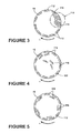
- Figure 3 illustrates a laundry load, including an imbalance, in a drum of the laundry treating appliance of Figure 1 , during a spin phase of a cycle of operation.
- Figure 4 illustrates the position of the laundry load in the drum as it is redistributed during the cycle of operation.
- Figure 5 illustrates the position of the laundry load in the drum after the imbalance has been sufficiently eliminated.
- Figure 6 is a flow chart illustrating a method of operating the washing machine according to a second embodiment of the invention.
- FIG. 1 is a schematic view of a laundry treating appliance according to a first embodiment of the invention.
- the laundry treating appliance may be any appliance which performs a cycle of operation to clean or otherwise treat items placed therein, non-limiting examples of which include a horizontal or vertical axis clothes washer; a combination washing machine and dryer; a dispensing dryer; a tumbling or stationary refreshing/revitalizing machine; an extractor; a non-aqueous washing apparatus; and a revitalizing machine.
- the laundry treating appliance of Figure 1 is illustrated as a washing machine 10, which may include a structural support system comprising a cabinet 12 which defines a housing within which a laundry holding system resides.
- the cabinet 12 may be a housing having a chassis and/or a frame, defining an interior enclosing components typically found in a conventional washing machine, such as motors, pumps, fluid lines, controls, sensors, transducers, and the like. Such components will not be described further herein except as necessary for a complete understanding of the invention.
- the laundry holding system comprises a tub 14 supported within the cabinet 12 by a suitable suspension system and a drum 16 provided within the tub 14, the drum 16 defining at least a portion of a laundry treating chamber 18.
- the drum 16 may include a plurality of perforations 20 such that liquid may flow between the tub 14 and the drum 16 through the perforations 20.
- a plurality of baffles 22 may be disposed on an inner surface of the drum 16 to lift the laundry load received in the treating chamber 18 while the drum 16 rotates. It is also within the scope of the invention for the laundry holding system to comprise only a tub with the tub defining the laundry treating chamber.
- the laundry holding system may further include a door 24 which may be movably mounted to the cabinet 12 to selectively close both the tub 14 and the drum 16.
- a bellows 26 may couple an open face of the tub 14 with the cabinet 12, with the door 24 sealing against the bellows 26 when the door 24 closes the tub 14.
- the washing machine 10 may further include a suspension system 28 for dynamically suspending the laundry holding system within the structural support system.
- the washing machine 10 may further include a liquid supply system for supplying water to the washing machine 10 for use in treating laundry during a cycle of operation.
- the liquid supply system may include a source of water, such as a household water supply 40, which may include separate valves 42 and 44 for controlling the flow of hot and cold water, respectively.
- Water may be supplied through an inlet conduit 46 directly to the tub 14 by controlling first and second diverter mechanisms 48 and 50, respectively.
- the diverter mechanisms 48, 50 may be a diverter valve having two outlets such that the diverter mechanisms 48, 50 may selectively direct a flow of liquid to one or both of two flow paths.
- Water from the household water supply 40 may flow through the inlet conduit 46 to the first diverter mechanism 48 which may direct the flow of liquid to a supply conduit 52.
- the second diverter mechanism 50 on the supply conduit 52 may direct the flow of liquid to a tub outlet conduit 54 which may be provided with a spray nozzle 56 configured to spray the flow of liquid into the tub 14. In this manner, water from the household water supply 40 may be supplied directly to the tub 14.
- the washing machine 10 may also be provided with a dispensing system for dispensing treating chemistry to the treating chamber 18 for use in treating the laundry according to a cycle of operation.
- the dispensing system may include a dispenser 62 which may be a single use dispenser, a bulk dispenser or a combination of a single and bulk dispenser.
- suitable dispensers are disclosed in U.S. Pub. No. 2010/0000022 to Hendrickson et al., filed July 1, 2008 , entitled "Household Cleaning Appliance with a Dispensing System Operable Between a Single Use Dispensing System and a Bulk Dispensing System," U.S. Pub. No.
- the dispenser 62 may be configured to dispense a treating chemistry directly to the tub 14 or mixed with water from the liquid supply system through a dispensing outlet conduit 64.
- the dispensing outlet conduit 64 may include a dispensing nozzle 66 configured to dispense the treating chemistry into the tub 14 in a desired pattern and under a desired amount of pressure.
- the dispensing nozzle 66 may be configured to dispense a flow or stream of treating chemistry into the tub 14 by gravity, i.e. a non-pressurized stream.
- Water may be supplied to the dispenser 62 from the supply conduit 52 by directing the diverter mechanism 50 to direct the flow of water to a dispensing supply conduit 68.
- Non-limiting examples of treating chemistries that may be dispensed by the dispensing system during a cycle of operation include one or more of the following: water, enzymes, fragrances, stiffness/sizing agents, wrinkle releasers/reducers, softeners, antistatic or electrostatic agents, stain repellants, water repellants, energy reduction/extraction aids, antibacterial agents, medicinal agents, vitamins, moisturizers, shrinkage inhibitors, and color fidelity agents, and combinations thereof.
- the washing machine 10 may also include a recirculation and drain system for recirculating liquid within the laundry holding system and draining liquid from the washing machine 10.
- Liquid supplied to the tub 14 through tub outlet conduit 54 and/or the dispensing supply conduit 68 typically enters a space between the tub 14 and the drum 16 and may flow by gravity to a sump 70 formed in part by a lower portion of the tub 14.
- the sump 70 may also be formed by a sump conduit 72 that may fluidly couple the lower portion of the tub 14 to a pump 74.
- the pump 74 may direct liquid to a drain conduit 76, which may drain the liquid from the washing machine 10, or to a recirculation conduit 78, which may terminate at a recirculation inlet 80.
- the recirculation inlet 80 may direct the liquid from the recirculation conduit 78 into the drum 16.
- the recirculation inlet 80 may introduce the liquid into the drum 16 in any suitable manner, such as by spraying, dripping, or providing a steady flow of liquid. In this manner, liquid provided to the tub 14, with or without treating chemistry may be recirculated into the treating chamber 18 for treating the laundry within.
- the liquid supply and/or recirculation and drain system may be provided with a heating system which may include one or more devices for heating laundry and/or liquid supplied to the tub 14, such as a steam generator 82 and/or a sump heater 84.
- Liquid from the household water supply 40 may be provided to the steam generator 82 through the inlet conduit 46 by controlling the first diverter mechanism 48 to direct the flow of liquid to a steam supply conduit 86.
- Steam generated by the steam generator 82 may be supplied to the tub 14 through a steam outlet conduit 87.
- the steam generator 82 may be any suitable type of steam generator such as a flow through steam generator or a tank-type steam generator.
- the sump heater 84 may be used to generate steam in place of or in addition to the steam generator 82.
- the steam generator 82 and/or sump heater 84 may be used to heat the laundry and/or liquid within the tub 14 as part of a cycle of operation.
- liquid supply and recirculation and drain system may differ from the configuration shown in Figure 1 , such as by inclusion of other valves, conduits, treating chemistry dispensers, sensors, such as water level sensors and temperature sensors, and the like, to control the flow of liquid through the washing machine 10 and for the introduction of more than one type of treating chemistry.
- the washing machine 10 also includes a drive system for rotating the drum 16 within the tub 14.
- the drive system may include a motor 88, which may be directly coupled with the drum 16 through a drive shaft 90 to rotate the drum 16 about a rotational axis during a cycle of operation.
- the motor 88 may be a brushless permanent magnet (BPM) motor having a stator 92 and a rotor 94. Alternately, the motor 88 may be coupled to the drum 16 through a belt and a drive shaft to rotate the drum 16, as is known in the art.
- Other motors such as an induction motor or a permanent split capacitor (PSC) motor, may also be used.
- the motor 88 may rotationally drive the drum 16 including that the motor 88 may rotate the drum 16 at various speeds in either rotational direction.
- the washing machine 10 also includes a control system for controlling the operation of the washing machine 10 to implement one or more cycles of operation.
- the control system may include a controller 96 located within the cabinet 12 and a user interface 98 that is operably coupled with the controller 96.
- the user interface 98 may include one or more knobs, dials, switches, displays, touch screens and the like for communicating with the user, such as to receive input and provide output.
- the user may enter different types of information including, without limitation, cycle selection and cycle parameters, such as cycle options.
- the controller 96 may include the machine controller and any additional controllers provided for controlling any of the components of the washing machine 10.
- the controller 96 may include the machine controller and a motor controller.
- Many known types of controllers may be used for the controller 96.
- the specific type of controller is not germane to the invention.
- the controller is a microprocessor-based controller that implements control software and sends/receives one or more electrical signals to/from each of the various working components to effect the control software.
- proportional control (P), proportional integral control (PI), and proportional derivative control (PD), or a combination thereof, a proportional integral derivative control (PID control) may be used to control the various components.
- the controller 96 may be provided with a memory 100 and a central processing unit (CPU) 102.
- the memory 100 may be used for storing the control software that is executed by the CPU 102 in completing a cycle of operation using the washing machine 10 and any additional software. Examples, without limitation, of cycles of operation include: wash, heavy duty wash, delicate wash, quick wash, pre-wash, refresh, rinse only, and timed wash.
- the memory 100 may also be used to store information, such as a database or table, and to store data received from one or more components of the washing machine 10 that may be communicably coupled with the controller 96.
- the database or table may be used to store the various operating parameters for the one or more cycles of operation, including factory default values for the operating parameters and any adjustments to them by the control system or by user input.
- a table 120 may include a table of a plurality of satellizing speed ranges.
- the controller 96 may be operably coupled with one or more components of the washing machine 10 for communicating with and controlling the operation of the component to complete a cycle of operation.
- the controller 96 may be operably coupled with the motor 88, the pump 74, the dispenser 62, the steam generator 82 and the sump heater 84 to control the operation of these and other components to implement one or more of the cycles of operation.
- the controller 96 may also be coupled with one or more sensors 104 provided in one or more of the systems of the washing machine 10 to receive input from the sensors, which are known in the art and not shown for simplicity.
- sensors 104 that may be communicably coupled with the controller 96 include: a treating chamber temperature sensor, a moisture sensor, a weight sensor, a chemical sensor, a position sensor, an imbalance sensor, and a motor torque sensor, which may be used to determine a variety of system and laundry characteristics, such as laundry load inertia or mass.
- one or more load size sensors or load amount sensors 106 may also be included in the washing machine 10 and may be positioned in any suitable location for detecting the amount of laundry, either quantitative (inertia, mass, weight, etc.) or qualitative (small, medium, large, etc.) within the treating chamber 18.
- the load amount sensors 106 may provide a size output to the controller 96 indicative of an amount of the laundry in the treating chamber 18.
- the amount of laundry in the treating chamber may be determined based on the weight of the laundry and/or the volume of laundry in the treating chamber.
- the one or more load amount sensors 106 may output a signal indicative of either the weight of the laundry load in the treating chamber 18 or the volume of the laundry load in the treating chamber 18.
- the one or more load amount sensors 106 may be any suitable type of sensor capable of measuring the weight or volume of laundry in the treating chamber 18.
- load amount sensors 106 for measuring the weight of the laundry may include load volume, pressure, or force transducers which may include, for example, load cells and strain gauges. It has been contemplated that the one or more such load amount sensors 106 may be operably coupled to the suspension system 28 to sense the weight borne by the suspension system 28. The weight borne by the suspension system 28 correlates to the weight of the laundry loaded into the treating chamber 18 such that the load amount sensor 106 may indicate the weight of the laundry loaded in the treating chamber 18.
- an IR or optical based sensor may be used to determine the volume of laundry located in the treating chamber 18.
- the washing machine 10 may have one or more pairs of feet 108 ( Figure 1 ) extending from the cabinet 12 and supporting the cabinet 12 on the floor and that a weight sensor (not shown) may be operably coupled to at least one of the feet 108 to sense the weight borne by that foot 108, which correlates to the weight of the laundry loaded into the treating chamber 18.
- the amount of laundry within the treating chamber 18 may be determined based on motor sensor output, such as output from a motor torque sensor.
- the motor torque is a function of the inertia of the rotating drum and laundry.
- a speed sensor 111 may also be included in the washing machine 10 and may be positioned in any suitable location for detecting and indicating a speed output indicative of a rotational speed of the drum 16.
- a speed sensor 111 may be any suitable speed sensor capable of providing an output indicative of the speed of the drum 16. It is also contemplated that the rotational speed of the drum 16 may also be determined based on a motor speed; thus, the speed sensor 111 may include a motor speed sensor for determining a speed output indicative of the rotational speed of the motor 88.
- the motor speed sensor may be a separate component, or may be integrated directly into the motor 88. Regardless of the type of speed sensor employed, or the coupling of the drum 16 with the motor 88, the speed sensor 111 may be adapted to enable the controller 96 to determine the rotational speed of the drum 16 from the rotational speed of the motor 88.
- the previously described washing machine 10 may be used to implement one or more embodiments of the invention.
- the embodiments of the method of the invention may be used to control the operation of the washing machine 10 to alter execution of the at least one cycle of operation when a determined satellizing speed is not within the satellizing speed range. Such alteration may prove beneficial as the determined satellizing speed may be used in other aspects of the cycle of operation such as when laundry is being distributed within the treating chamber 18 to provide for an acceptable amount of imbalance.
- the motor 88 may rotate the drum 16 at various speeds in either rotational direction.
- the motor 88 can rotate the drum 16 at speeds to effect various types of laundry load 112 movement inside the drum 16.
- the laundry load may undergo at least one of tumbling, rolling (also called balling), sliding, satellizing (also called plastering), and combinations thereof.
- the drum 16 is rotated at a tumbling speed such that the fabric items in the drum 16 rotate with the drum 16 from a lowest location of the drum 16 towards a highest location of the drum 16, but fall back to the lowest location before reaching the highest location.
- the centrifugal force applied by the drum to the fabric items at the tumbling speeds is less than about 1G.
- the motor 88 may rotate the drum 16 at rotational speeds, i.e. a spin speed, wherein the fabric items are held against the inner surface of the drum and rotate with the drum 16 without falling. This is known as the laundry being satellized or plastered against the drum.
- the force applied to the fabric items at the satellizing speeds is greater than or about equal to 1G.
- the drum 16 may rotate about an axis that is inclined relative to the horizontal, in which case the term "1G" refers to the vertical component of the centrifugal force vector, and the total magnitude along the centrifugal force vector would therefore be greater than 1 G.
- the terms tumbling, rolling, sliding and satellizing are terms of art that may be used to describe the motion of some or all of the fabric items forming the laundry load. However, not all of the fabric items forming the laundry load need exhibit the motion for the laundry load to be described accordingly. Further, the rotation of the fabric items with the drum 16 may be facilitated by the baffles 22.
- Centrifugal force is a function of a mass (m) of an object (laundry item 116), an angular velocity ( ⁇ ) of the object, and a distance, or radius (r) at which the object is located with respect to an axis of rotation, or a drum axis.
- ⁇ mass of an object
- r radius
- the equation for the centrifugal force (CF) acting on a laundry item 116 within the drum 16 is:
- C ⁇ F m * ⁇ 2 * r
- the centrifugal force (CF) acting on any single item 116 in the laundry load 112 can be modeled by the distance the center of gravity of that item 116 is from the axis of rotation of the drum 16.
- CF centrifugal force
- the elimination of the imbalance 114 means that the imbalance 114 is reduced below a maximum magnitude suitable for the operating conditions. It does not require a complete removal of the imbalance 114. In many cases, the suspension system 28 in the washing machine 10 may accommodate a certain amount of imbalance 114. Thus, it is not necessary to completely remove the entire imbalance 114.
- FIGS 3-5 graphically illustrate such a method.
- an unequally distributed laundry load 112 is shown in the treating chamber 18 defined by the drum 16 during a spin phase wherein the treating chamber 18 is rotated at a spin speed sufficient to apply a centrifugal force greater than that required to satellize the entire laundry load 112, thereby, satellizing the laundry load 112.
- CF centrifugal force
- the centrifugal force (CF) exhibited on the individual laundry items 116 will vary along the radius of the treating chamber 18. Accordingly, the closer the laundry item 116 lies to the axis of rotation, the smaller the centrifugal force (CF) acting thereon. Therefore, to satellize all of the laundry items 116, the treating chamber 18 must be rotated at a spin speed sufficient that the centrifugal force (CF) acting on all of the laundry items 116 is greater than the gravity force acting thereon. It can be correlated that the laundry items 116 pressed against the inner peripheral wall of the treating chamber 18 experience greater centrifugal force (CF) than the laundry items 116 lying closer to the axis of rotation.
- the imbalance 114 can be seen in the treating chamber 18, as circled in Figure 3 .
- the imbalance 114 is due to the uneven distribution of the laundry items 116 within the treating chamber 18. Further, the laundry items 116 that create the imbalance 114 will necessarily be those laundry items 116 that are closest to the axis of rotation.
- Figure 4 illustrates the position of the laundry load 112 in the treating chamber 18 during a redistribution phase wherein the treating chamber 18 is slowed from the speed of Figure 3 and rotated at a speed such that some of the laundry items 116 experience less than a centrifugal force required to satellize them, while the remaining laundry items 116 experience a centrifugal force required to satellize them or greater than a centrifugal force required to satellize them.
- FIG. 5 illustrates the position where the imbalance 114 is eliminated by a sufficient redistribution and the rotational speed of the treating chamber 18 has been increased again to the spin speed sufficient to satellize the entire laundry load 112.
- the deceleration of the drum 16 and acceleration of the drum 16 may include the controller 96 operating the motor 88 such that the speed of the drum 16 is dropped just below the satellizing speed and then brought back up to the satellizing speed such that the speed of the drum 16 oscillates around the satellizing speed, this is sometimes referred to as a short distribution.
- the deceleration of the drum 16 and acceleration of the drum 16 may include the controller 96 stopping the rotation of the drum 16 altogether and then bringing the drum 16 back up to the satellizing speed, this is sometimes referred to as a long distribution. Regardless of the type of distribution, an accurate satellizing speed is beneficial for the controller 96 to have and use.
- the controller 96 may attempt to satellize the laundry items and the laundry items may instead tumble. If the determined satellizing speed is higher than the actual satellizing speed, the controller 96 may attempt to redistribute the laundry by tumbling some of the laundry items and the laundry items may instead remain plastered to the drum 16.
- FIG. 6 a flow chart of a method 200 for altering execution of the at least one cycle of operation of the washing machine 10 when the determined satellizing speed is not within a set satellizing speed range is illustrated.
- the sequence of steps depicted for this method is for illustrative purposes only, and is not meant to limit the method in any way as it is understood that the steps may proceed in a different logical order or additional or intervening steps may be included without detracting from the invention.
- the method 200 starts with assuming that the user has placed one or more laundry items 116 for treatment within the treating chamber 18 and selected a cycle of operation through the user interface 98.
- the method 200 may be implemented during any portion of a cycle of operation or may be implemented as a separate cycle of operation.
- the controller 96 may determine an amount of the laundry load within the treating chamber 18.
- the amount of laundry may be qualitative or quantitative.
- a qualitative determination of the laundry amount may include determining whether the laundry is an extra-small, small, medium, large or extra-large load, or any other suitable qualitative grouping.
- a quantitative determination may include determining a weight or volume of the laundry within the treating chamber 18.
- the determination of the inertia value may be made during an acceleration ramp of the drum such as when the drum is being accelerated at 206 or at an initial acceleration of the drum used to determine the amount of the laundry load.
- the controller 96 may determine the inertia value by determining a motor torque and this may be determined based on a motor sensor output, such as output from a motor torque sensor.
- the motor torque may be a function of the inertia of the rotating drum and laundry load. Generally, the greater the inertia of the rotating drum and laundry, the greater the motor torque.
- the amount of laundry may also be determined manually based on user input through the user interface 98 or automatically by the washing machine 10 such as through the load amount sensors 106.
- a satellizing speed range may be set by the controller 96 based on the amount of the laundry load determined at 202. More specifically, the controller 96 may set a satellizing speed range based on the size output from the size sensors 106. Setting the satellizing speed range may include selecting a predetermined satellizing speed range based on the determined amount of laundry, which may include selecting a predetermined satellizing speed range from a plurality of satellizing speed ranges.
- the predetermined satellizing speed range may be found by the controller 96 conducting a table look-up of the satellizing speed range from a table of a plurality of satellizing speed ranges such as the table 120, which contains a plurality of satellizing speed ranges.
- the controller 96 may determine the satellizing speed range based on where the determined amount of laundry falls within a range of amounts of laundry. For example, a predetermined satellizing speed range may be provided if the load amount falls in the range of an extra-small to a small load amount.
- the controller 96 may accelerate the drum 16 through operation of the motor 88 through a satellizing speed for the laundry. Accelerating the drum 16 through the satellizing speed may include accelerating the drum 16 from a non-satellizing speed, where at least some of the laundry is not satellized. The drum 16 may be accelerated from the non-satellizing speed to a satellizing speed, where all of the laundry is satellized.
- the controller 96 may accelerate the drum 16 through a satellizing speed for the laundry and may determine the rotational speed of the drum 16 at which the laundry satellizes to define a determined satellizing speed, as indicated at 208.
- the controller 96 may determine the satellizing speed by determining a rotational speed of the drum 16 when a high frequency component of a torque signal of the motor 88 satisfies a reference value.
- the satellizing speed may be determined by determining a rotational speed of the drum 16 when the torque signal of motor 88 matches a reference torque signal. While the satellizing speed may be determined in either of these ways it will be understood that any method for determining the satellization speed may be used as the method of determining is not germane to the invention.
- the controller 96 may compare the determined satellizing speed to the satellizing speed range. This comparison may include determining whether the determined satellizing speed falls within the satellizing speed range.
- the term "within" the satellizing speed range is used herein to mean including or excluding the upper and lower values of the range.
- the satellizing speed range and comparison may be presented in the controller 96 in any suitable manner including for example a formula or algorithm, a high and low point, a single point, a delta, etc.
- the controller may continue with the cycle of operation without alteration, as indicated at 212. This may include using the determined satellizing speed in any subsequent calculations or operations. If the determined satellizing speed falls outside the satellizing speed range, the controller 96 may alter execution of the at least one cycle of operation when the determined satellizing speed is not within the satellizing speed range as indicated at 214. The controller 96 may alter execution of the at least one cycle of operation in a variety of ways including by setting an operational parameter for the cycle of operation based on the comparison.
- the controller 96 may use a default satellizing speed in place of the determined satellizing speed when the determined satellizing speed falls outside the satellizing speed range. This may ensure that any further uses of the satellizing speed such as for redistribution purposes uses a default value as opposed to the determined value. In such an instance the determined satellizing speed value may be discarded for the remainder of the cycle of operation.
- the controller 96 may alternatively, or in addition to using a default value, alter execution of the at least one cycle of operation by at least one of initiating, altering, and ceasing a phase of the at least one cycle of operation.
- the controller 96 may initiate a re-distribution phase to redistribute the laundry within the treating chamber 18 when the satellizing speed falls outside the satellizing range.
- the satellizing speed ranges including those in the table of a plurality of satellizing speed ranges may be updated based on determined satellizing speed ranges that are determined to be within the appropriate satellizing speed range. In this manner the speed ranges in the table 120 may be updated with historical spin speeds enabling the table 120 to be adapted to the specific loads run by the user over time.
- the method 200 illustrated is merely for illustrative purposes. It is further noted that rarely is it necessary from a practical perspective to actually calculate the value at issue. For example, in the case of the amount of the load, motor torque and/or inertia are typically proportional to the amount, rendering unnecessary to actually calculate the amount. Further, the motor torque and/or inertia are typically proportional to a voltage level of an output signal from a sensor, such as a torque sensor. Thus, to determine the amount of laundry, one need only obtain the voltage value and compare it to a reference voltage value for the corresponding load amount. In all of the above cases the setting of the satellizing speed range based on the determined amount of laundry may include setting the satellizing speed range based on the voltage level instead of the corresponding load amount.
- the above described embodiments provided a variety of benefits including that the cycle of operation of the laundry treating appliance may be operated in an effective and efficient manner.
- the embodiments of the invention described allow a determined satellizing speed to be verified for accuracy.
- the appliance may then use either the appropriate determined value or a corrected value in subsequent portions of the cycle of operation. For example, using either an appropriate determined value or a corrected value allows the laundry to be actually redistributed and more quickly redistributed than would occur if an unacceptable value were used.
Landscapes
- Engineering & Computer Science (AREA)
- Textile Engineering (AREA)
- Control Of Washing Machine And Dryer (AREA)
Abstract
Description
- Laundry treating appliances, such as clothes washers, refreshers, and non-aqueous systems, may have a configuration based on a rotating drum that defines a treating chamber in which laundry items are placed for treating according to one or more cycles of operation. The laundry treating appliance may have a controller that implements the cycles of operation having one or more operating parameters. The controller may control a motor to rotate the drum according to one of the cycles of operation. The controller may control the motor to rotate the drum at the same speeds for a give cycle of operation regardless of the characteristics of the laundry items.
- According to an embodiment of the invention, a method of operating a laundry treating appliance having a rotatable drum at least partially defining a treating chamber for receiving laundry for treatment according to at least one cycle of operation, includes determining an amount of the laundry in the treating chamber, setting a satellizing speed range based on the determined amount of laundry, accelerating the drum through a satellizing speed for the laundry, determining the speed at which the laundry satellizes to define a determined satellizing speed, comparing the determined satellizing speed to the satellizing speed range, and altering execution of the at least one cycle of operation when the determined satellizing speed is not within the satellizing speed range.
- According to another embodiment of the invention, a laundry treating appliance for treating laundry according to at least one cycle of operation includes a rotatable drum at least partially defining a treating chamber, a motor rotationally driving the drum, a laundry size sensor, a speed sensor, and a controller receiving as inputs the size output and the speed output, and controlling the motor to control the rotational speed of the drum to implement the at least one cycle of operation by setting a satellizing speed range, accelerating the drum through a satellizing speed for the laundry, determining the rotational speed of the drum at which the laundry satellizes to define a determined satellizing speed, comparing the determined satellizing speed to the satellizing speed range, and altering execution of the at least one cycle of operation when the determined satellizing speed is not within the satellizing speed range.
- In the drawings:
-
Figure 1 is a schematic view of a laundry treating appliance in the form of a washing machine according to a first embodiment of the invention. -
Figure 2 is a schematic of a control system of the laundry treating appliance ofFigure 1 according to the first embodiment of the invention. -
Figure 3 illustrates a laundry load, including an imbalance, in a drum of the laundry treating appliance ofFigure 1 , during a spin phase of a cycle of operation. -
Figure 4 illustrates the position of the laundry load in the drum as it is redistributed during the cycle of operation. -
Figure 5 illustrates the position of the laundry load in the drum after the imbalance has been sufficiently eliminated. -
Figure 6 is a flow chart illustrating a method of operating the washing machine according to a second embodiment of the invention. -
Figure 1 is a schematic view of a laundry treating appliance according to a first embodiment of the invention. The laundry treating appliance may be any appliance which performs a cycle of operation to clean or otherwise treat items placed therein, non-limiting examples of which include a horizontal or vertical axis clothes washer; a combination washing machine and dryer; a dispensing dryer; a tumbling or stationary refreshing/revitalizing machine; an extractor; a non-aqueous washing apparatus; and a revitalizing machine. - The laundry treating appliance of
Figure 1 is illustrated as awashing machine 10, which may include a structural support system comprising acabinet 12 which defines a housing within which a laundry holding system resides. Thecabinet 12 may be a housing having a chassis and/or a frame, defining an interior enclosing components typically found in a conventional washing machine, such as motors, pumps, fluid lines, controls, sensors, transducers, and the like. Such components will not be described further herein except as necessary for a complete understanding of the invention. - The laundry holding system comprises a
tub 14 supported within thecabinet 12 by a suitable suspension system and adrum 16 provided within thetub 14, thedrum 16 defining at least a portion of a laundry treating chamber 18. Thedrum 16 may include a plurality ofperforations 20 such that liquid may flow between thetub 14 and thedrum 16 through theperforations 20. A plurality ofbaffles 22 may be disposed on an inner surface of thedrum 16 to lift the laundry load received in the treating chamber 18 while thedrum 16 rotates. It is also within the scope of the invention for the laundry holding system to comprise only a tub with the tub defining the laundry treating chamber. - The laundry holding system may further include a
door 24 which may be movably mounted to thecabinet 12 to selectively close both thetub 14 and thedrum 16. Abellows 26 may couple an open face of thetub 14 with thecabinet 12, with thedoor 24 sealing against thebellows 26 when thedoor 24 closes thetub 14. - The
washing machine 10 may further include asuspension system 28 for dynamically suspending the laundry holding system within the structural support system. - The
washing machine 10 may further include a liquid supply system for supplying water to thewashing machine 10 for use in treating laundry during a cycle of operation. The liquid supply system may include a source of water, such as ahousehold water supply 40, which may includeseparate valves inlet conduit 46 directly to thetub 14 by controlling first andsecond diverter mechanisms diverter mechanisms diverter mechanisms household water supply 40 may flow through theinlet conduit 46 to thefirst diverter mechanism 48 which may direct the flow of liquid to asupply conduit 52. Thesecond diverter mechanism 50 on thesupply conduit 52 may direct the flow of liquid to atub outlet conduit 54 which may be provided with aspray nozzle 56 configured to spray the flow of liquid into thetub 14. In this manner, water from thehousehold water supply 40 may be supplied directly to thetub 14. - The
washing machine 10 may also be provided with a dispensing system for dispensing treating chemistry to the treating chamber 18 for use in treating the laundry according to a cycle of operation. The dispensing system may include adispenser 62 which may be a single use dispenser, a bulk dispenser or a combination of a single and bulk dispenser. Non-limiting examples of suitable dispensers are disclosed inU.S. Pub. No. 2010/0000022 to Hendrickson et al., filed July 1, 2008 , entitled "Household Cleaning Appliance with a Dispensing System Operable Between a Single Use Dispensing System and a Bulk Dispensing System,"U.S. Pub. No. 2010/0000024 to Hendrickson et al., filed July 1, 2008 , entitled "Apparatus and Method for Controlling Laundering Cycle by Sensing Wash Aid Concentration,"U.S. Pub. No. 2010/0000573 to Hendrickson et al., filed July 1, 2008 , entitled "Apparatus and Method for Controlling Concentration of Wash Aid in Wash Liquid,"U.S. Pub. No. 2010/0000581 to Doyle et al., filed July 1, 2008 , entitled "Water Flow Paths in a Household Cleaning Appliance with Single Use and Bulk Dispensing,"U.S. Pub. No. 2010/0000264 to Luckman et al., filed July 1, 2008 , entitled "Method for Converting a Household Cleaning Appliance with a Non-Bulk Dispensing System to a Household Cleaning Appliance with a Bulk Dispensing System,"U.S. Pub. No. 2010/0000586 to Hendrickson, filed June 23, 2009 , entitled "Household Cleaning Appliance with a Single Water Flow Path for Both Non-Bulk and Bulk Dispensing," and Application No.13/093,132, filed April 25, 2011 - Regardless of the type of dispenser used, the
dispenser 62 may be configured to dispense a treating chemistry directly to thetub 14 or mixed with water from the liquid supply system through a dispensingoutlet conduit 64. The dispensingoutlet conduit 64 may include a dispensingnozzle 66 configured to dispense the treating chemistry into thetub 14 in a desired pattern and under a desired amount of pressure. For example, the dispensingnozzle 66 may be configured to dispense a flow or stream of treating chemistry into thetub 14 by gravity, i.e. a non-pressurized stream. Water may be supplied to thedispenser 62 from thesupply conduit 52 by directing thediverter mechanism 50 to direct the flow of water to a dispensingsupply conduit 68. - Non-limiting examples of treating chemistries that may be dispensed by the dispensing system during a cycle of operation include one or more of the following: water, enzymes, fragrances, stiffness/sizing agents, wrinkle releasers/reducers, softeners, antistatic or electrostatic agents, stain repellants, water repellants, energy reduction/extraction aids, antibacterial agents, medicinal agents, vitamins, moisturizers, shrinkage inhibitors, and color fidelity agents, and combinations thereof.
- The
washing machine 10 may also include a recirculation and drain system for recirculating liquid within the laundry holding system and draining liquid from thewashing machine 10. Liquid supplied to thetub 14 throughtub outlet conduit 54 and/or the dispensingsupply conduit 68 typically enters a space between thetub 14 and thedrum 16 and may flow by gravity to asump 70 formed in part by a lower portion of thetub 14. Thesump 70 may also be formed by asump conduit 72 that may fluidly couple the lower portion of thetub 14 to apump 74. Thepump 74 may direct liquid to adrain conduit 76, which may drain the liquid from thewashing machine 10, or to arecirculation conduit 78, which may terminate at arecirculation inlet 80. Therecirculation inlet 80 may direct the liquid from the recirculation conduit 78 into thedrum 16. Therecirculation inlet 80 may introduce the liquid into thedrum 16 in any suitable manner, such as by spraying, dripping, or providing a steady flow of liquid. In this manner, liquid provided to thetub 14, with or without treating chemistry may be recirculated into the treating chamber 18 for treating the laundry within. - The liquid supply and/or recirculation and drain system may be provided with a heating system which may include one or more devices for heating laundry and/or liquid supplied to the
tub 14, such as asteam generator 82 and/or asump heater 84. Liquid from thehousehold water supply 40 may be provided to thesteam generator 82 through theinlet conduit 46 by controlling thefirst diverter mechanism 48 to direct the flow of liquid to asteam supply conduit 86. Steam generated by thesteam generator 82 may be supplied to thetub 14 through asteam outlet conduit 87. Thesteam generator 82 may be any suitable type of steam generator such as a flow through steam generator or a tank-type steam generator. Alternatively, thesump heater 84 may be used to generate steam in place of or in addition to thesteam generator 82. In addition or alternatively to generating steam, thesteam generator 82 and/orsump heater 84 may be used to heat the laundry and/or liquid within thetub 14 as part of a cycle of operation. - Additionally, the liquid supply and recirculation and drain system may differ from the configuration shown in
Figure 1 , such as by inclusion of other valves, conduits, treating chemistry dispensers, sensors, such as water level sensors and temperature sensors, and the like, to control the flow of liquid through thewashing machine 10 and for the introduction of more than one type of treating chemistry. - The
washing machine 10 also includes a drive system for rotating thedrum 16 within thetub 14. The drive system may include amotor 88, which may be directly coupled with thedrum 16 through adrive shaft 90 to rotate thedrum 16 about a rotational axis during a cycle of operation. Themotor 88 may be a brushless permanent magnet (BPM) motor having astator 92 and arotor 94. Alternately, themotor 88 may be coupled to thedrum 16 through a belt and a drive shaft to rotate thedrum 16, as is known in the art. Other motors, such as an induction motor or a permanent split capacitor (PSC) motor, may also be used. Themotor 88 may rotationally drive thedrum 16 including that themotor 88 may rotate thedrum 16 at various speeds in either rotational direction. - The
washing machine 10 also includes a control system for controlling the operation of thewashing machine 10 to implement one or more cycles of operation. The control system may include acontroller 96 located within thecabinet 12 and auser interface 98 that is operably coupled with thecontroller 96. Theuser interface 98 may include one or more knobs, dials, switches, displays, touch screens and the like for communicating with the user, such as to receive input and provide output. The user may enter different types of information including, without limitation, cycle selection and cycle parameters, such as cycle options. - The
controller 96 may include the machine controller and any additional controllers provided for controlling any of the components of thewashing machine 10. For example, thecontroller 96 may include the machine controller and a motor controller. Many known types of controllers may be used for thecontroller 96. The specific type of controller is not germane to the invention. It is contemplated that the controller is a microprocessor-based controller that implements control software and sends/receives one or more electrical signals to/from each of the various working components to effect the control software. As an example, proportional control (P), proportional integral control (PI), and proportional derivative control (PD), or a combination thereof, a proportional integral derivative control (PID control), may be used to control the various components. - As illustrated in
Figure 2 , thecontroller 96 may be provided with amemory 100 and a central processing unit (CPU) 102. Thememory 100 may be used for storing the control software that is executed by theCPU 102 in completing a cycle of operation using thewashing machine 10 and any additional software. Examples, without limitation, of cycles of operation include: wash, heavy duty wash, delicate wash, quick wash, pre-wash, refresh, rinse only, and timed wash. Thememory 100 may also be used to store information, such as a database or table, and to store data received from one or more components of thewashing machine 10 that may be communicably coupled with thecontroller 96. The database or table may be used to store the various operating parameters for the one or more cycles of operation, including factory default values for the operating parameters and any adjustments to them by the control system or by user input. For example, a table 120 may include a table of a plurality of satellizing speed ranges. - The
controller 96 may be operably coupled with one or more components of thewashing machine 10 for communicating with and controlling the operation of the component to complete a cycle of operation. For example, thecontroller 96 may be operably coupled with themotor 88, thepump 74, thedispenser 62, thesteam generator 82 and thesump heater 84 to control the operation of these and other components to implement one or more of the cycles of operation. - The
controller 96 may also be coupled with one or more sensors 104 provided in one or more of the systems of thewashing machine 10 to receive input from the sensors, which are known in the art and not shown for simplicity. Non-limiting examples of sensors 104 that may be communicably coupled with thecontroller 96 include: a treating chamber temperature sensor, a moisture sensor, a weight sensor, a chemical sensor, a position sensor, an imbalance sensor, and a motor torque sensor, which may be used to determine a variety of system and laundry characteristics, such as laundry load inertia or mass. - In one example, one or more load size sensors or load amount sensors 106 may also be included in the
washing machine 10 and may be positioned in any suitable location for detecting the amount of laundry, either quantitative (inertia, mass, weight, etc.) or qualitative (small, medium, large, etc.) within the treating chamber 18. The load amount sensors 106 may provide a size output to thecontroller 96 indicative of an amount of the laundry in the treating chamber 18. By way of non-limiting example, it is contemplated that the amount of laundry in the treating chamber may be determined based on the weight of the laundry and/or the volume of laundry in the treating chamber. Thus, the one or more load amount sensors 106 may output a signal indicative of either the weight of the laundry load in the treating chamber 18 or the volume of the laundry load in the treating chamber 18. - The one or more load amount sensors 106 may be any suitable type of sensor capable of measuring the weight or volume of laundry in the treating chamber 18. Non-limiting examples of load amount sensors 106 for measuring the weight of the laundry may include load volume, pressure, or force transducers which may include, for example, load cells and strain gauges. It has been contemplated that the one or more such load amount sensors 106 may be operably coupled to the
suspension system 28 to sense the weight borne by thesuspension system 28. The weight borne by thesuspension system 28 correlates to the weight of the laundry loaded into the treating chamber 18 such that the load amount sensor 106 may indicate the weight of the laundry loaded in the treating chamber 18. In the case of a suitable load amount sensor 106 for determining volume it is contemplated that an IR or optical based sensor may be used to determine the volume of laundry located in the treating chamber 18. - Alternatively, it has been contemplated that the
washing machine 10 may have one or more pairs of feet 108 (Figure 1 ) extending from thecabinet 12 and supporting thecabinet 12 on the floor and that a weight sensor (not shown) may be operably coupled to at least one of thefeet 108 to sense the weight borne by thatfoot 108, which correlates to the weight of the laundry loaded into the treating chamber 18. In another example, the amount of laundry within the treating chamber 18 may be determined based on motor sensor output, such as output from a motor torque sensor. The motor torque is a function of the inertia of the rotating drum and laundry. There are many known methods for determining the load inertia, and thus the load mass, based on the motor torque. It will be understood that the details of the load amount sensors are not germane to the embodiments of the invention and that any suitable method and sensors may be used to determine the amount of laundry. - As another example, a speed sensor 111 may also be included in the
washing machine 10 and may be positioned in any suitable location for detecting and indicating a speed output indicative of a rotational speed of thedrum 16. Such a speed sensor 111 may be any suitable speed sensor capable of providing an output indicative of the speed of thedrum 16. It is also contemplated that the rotational speed of thedrum 16 may also be determined based on a motor speed; thus, the speed sensor 111 may include a motor speed sensor for determining a speed output indicative of the rotational speed of themotor 88. The motor speed sensor may be a separate component, or may be integrated directly into themotor 88. Regardless of the type of speed sensor employed, or the coupling of thedrum 16 with themotor 88, the speed sensor 111 may be adapted to enable thecontroller 96 to determine the rotational speed of thedrum 16 from the rotational speed of themotor 88. - The previously described
washing machine 10 may be used to implement one or more embodiments of the invention. The embodiments of the method of the invention may be used to control the operation of thewashing machine 10 to alter execution of the at least one cycle of operation when a determined satellizing speed is not within the satellizing speed range. Such alteration may prove beneficial as the determined satellizing speed may be used in other aspects of the cycle of operation such as when laundry is being distributed within the treating chamber 18 to provide for an acceptable amount of imbalance. - Prior to describing a method of operation of the
washing machine 10, a brief summary of the underlying physical phenomena may be useful to aid in the overall understanding. Themotor 88 may rotate thedrum 16 at various speeds in either rotational direction. In particular, themotor 88 can rotate thedrum 16 at speeds to effect various types oflaundry load 112 movement inside thedrum 16. For example, the laundry load may undergo at least one of tumbling, rolling (also called balling), sliding, satellizing (also called plastering), and combinations thereof. During tumbling, thedrum 16 is rotated at a tumbling speed such that the fabric items in thedrum 16 rotate with thedrum 16 from a lowest location of thedrum 16 towards a highest location of thedrum 16, but fall back to the lowest location before reaching the highest location. Typically, the centrifugal force applied by the drum to the fabric items at the tumbling speeds is less than about 1G. During satellizing, themotor 88 may rotate thedrum 16 at rotational speeds, i.e. a spin speed, wherein the fabric items are held against the inner surface of the drum and rotate with thedrum 16 without falling. This is known as the laundry being satellized or plastered against the drum. Typically, the force applied to the fabric items at the satellizing speeds is greater than or about equal to 1G. For a horizontalaxis washing machine 10, thedrum 16 may rotate about an axis that is inclined relative to the horizontal, in which case the term "1G" refers to the vertical component of the centrifugal force vector, and the total magnitude along the centrifugal force vector would therefore be greater than 1 G. The terms tumbling, rolling, sliding and satellizing are terms of art that may be used to describe the motion of some or all of the fabric items forming the laundry load. However, not all of the fabric items forming the laundry load need exhibit the motion for the laundry load to be described accordingly. Further, the rotation of the fabric items with thedrum 16 may be facilitated by thebaffles 22. - Centrifugal force (CF) is a function of a mass (m) of an object (laundry item 116), an angular velocity (ω) of the object, and a distance, or radius (r) at which the object is located with respect to an axis of rotation, or a drum axis. Specifically, the equation for the centrifugal force (CF) acting on a
laundry item 116 within thedrum 16 is:
- The centrifugal force (CF) acting on any
single item 116 in thelaundry load 112 can be modeled by the distance the center of gravity of thatitem 116 is from the axis of rotation of thedrum 16. Thus, when thelaundry items 116 are stacked upon each other, which is often the case, those items having a center of gravity closer to the axis of rotation experience a smaller magnitude centrifugal force (CF) than those items having a center of gravity farther away. It is possible to slow the speed of rotation of thedrum 16 such that thecloser items 116 will experience a centrifugal force (CF) less than the force required to satellize them, permitting them to tumble, while the farther awayitems 116 still experience a centrifugal force (CF) equal to or greater than the force required to satellize them, retaining them in a fixed position relative to thedrum 16. Using such a control of the speed of thedrum 16, it is possible to control the speed of thedrum 16 such that thecloser items 116 may tumble within thedrum 16 while thefarther items 116 remain fixed. This method may be used to eliminate animbalance 114 caused by a mass of stackedlaundry items 116 because an imbalance is often caused by a localized "piling" ofitems 116. - As used in this description, the elimination of the
imbalance 114 means that theimbalance 114 is reduced below a maximum magnitude suitable for the operating conditions. It does not require a complete removal of theimbalance 114. In many cases, thesuspension system 28 in thewashing machine 10 may accommodate a certain amount ofimbalance 114. Thus, it is not necessary to completely remove theentire imbalance 114. -
Figures 3-5 graphically illustrate such a method. Beginning withFigure 3 , an unequally distributedlaundry load 112 is shown in the treating chamber 18 defined by thedrum 16 during a spin phase wherein the treating chamber 18 is rotated at a spin speed sufficient to apply a centrifugal force greater than that required to satellize theentire laundry load 112, thereby, satellizing thelaundry load 112. However, it can also be seen that not all thelaundry items 116 that make up thelaundry load 112 are located an equal distance from the axis of rotation. Following the above equation, the centrifugal force (CF) acting on eachlaundry item 116 in the treating chamber 18 is proportional to the distance from the axis of rotation. Thus, along the radius of the treating chamber 18, the centrifugal force (CF) exhibited on theindividual laundry items 116 will vary. Accordingly, the closer thelaundry item 116 lies to the axis of rotation, the smaller the centrifugal force (CF) acting thereon. Therefore, to satellize all of thelaundry items 116, the treating chamber 18 must be rotated at a spin speed sufficient that the centrifugal force (CF) acting on all of thelaundry items 116 is greater than the gravity force acting thereon. It can be correlated that thelaundry items 116 pressed against the inner peripheral wall of the treating chamber 18 experience greater centrifugal force (CF) than thelaundry items 116 lying closer to the axis of rotation. In other words, during the spin phase and satellization of thelaundry load 112, all of thelaundry items 116 are experiencing centrifugal force greater than the force required to satellize them, yet not all of thelaundry items 116 are experiencing the same centrifugal force (CF). - The
imbalance 114 can be seen in the treating chamber 18, as circled inFigure 3 . Theimbalance 114 is due to the uneven distribution of thelaundry items 116 within the treating chamber 18. Further, thelaundry items 116 that create theimbalance 114 will necessarily be thoselaundry items 116 that are closest to the axis of rotation.Figure 4 illustrates the position of thelaundry load 112 in the treating chamber 18 during a redistribution phase wherein the treating chamber 18 is slowed from the speed ofFigure 3 and rotated at a speed such that some of thelaundry items 116 experience less than a centrifugal force required to satellize them, while the remaininglaundry items 116 experience a centrifugal force required to satellize them or greater than a centrifugal force required to satellize them. According to the principals described above, as the rotational speed of the treating chamber 18 is reduced, thelaundry item 116 or items that contributed to theimbalance 114 will begin to tumble and will be redistributed. Upon redistribution, the treating chamber 18 may be accelerated once again to a speed sufficient to satellize all of thelaundry items 116.Figure 5 illustrates the position where theimbalance 114 is eliminated by a sufficient redistribution and the rotational speed of the treating chamber 18 has been increased again to the spin speed sufficient to satellize theentire laundry load 112. - The deceleration of the
drum 16 and acceleration of thedrum 16 may include thecontroller 96 operating themotor 88 such that the speed of thedrum 16 is dropped just below the satellizing speed and then brought back up to the satellizing speed such that the speed of thedrum 16 oscillates around the satellizing speed, this is sometimes referred to as a short distribution. Alternatively, the deceleration of thedrum 16 and acceleration of thedrum 16 may include thecontroller 96 stopping the rotation of thedrum 16 altogether and then bringing thedrum 16 back up to the satellizing speed, this is sometimes referred to as a long distribution. Regardless of the type of distribution, an accurate satellizing speed is beneficial for thecontroller 96 to have and use. If the determined satellizing speed is lower than the actual satellizing speed, thecontroller 96 may attempt to satellize the laundry items and the laundry items may instead tumble. If the determined satellizing speed is higher than the actual satellizing speed, thecontroller 96 may attempt to redistribute the laundry by tumbling some of the laundry items and the laundry items may instead remain plastered to thedrum 16. - Referring now to
Figure 6 , a flow chart of amethod 200 for altering execution of the at least one cycle of operation of thewashing machine 10 when the determined satellizing speed is not within a set satellizing speed range is illustrated. The sequence of steps depicted for this method is for illustrative purposes only, and is not meant to limit the method in any way as it is understood that the steps may proceed in a different logical order or additional or intervening steps may be included without detracting from the invention. Themethod 200 starts with assuming that the user has placed one ormore laundry items 116 for treatment within the treating chamber 18 and selected a cycle of operation through theuser interface 98. Themethod 200 may be implemented during any portion of a cycle of operation or may be implemented as a separate cycle of operation. - At 202, the
controller 96 may determine an amount of the laundry load within the treating chamber 18. The amount of laundry may be qualitative or quantitative. For example, a qualitative determination of the laundry amount may include determining whether the laundry is an extra-small, small, medium, large or extra-large load, or any other suitable qualitative grouping. A quantitative determination may include determining a weight or volume of the laundry within the treating chamber 18. For example, the determining the amount of laundry may include determining a load mass of the laundry load. This may include determining an inertia value indicative of the inertia of the laundry load. Determining the inertia of the laundry may include determining the inertia of the laundry and/or determining the inertia of the rotating drum and laundry. The determination of the inertia value may be made during an acceleration ramp of the drum such as when the drum is being accelerated at 206 or at an initial acceleration of the drum used to determine the amount of the laundry load. Thecontroller 96 may determine the inertia value by determining a motor torque and this may be determined based on a motor sensor output, such as output from a motor torque sensor. The motor torque may be a function of the inertia of the rotating drum and laundry load. Generally, the greater the inertia of the rotating drum and laundry, the greater the motor torque. There are many methods for determining the load inertia, and the load mass, based on the motor torque and such a determination method is not germane to the invention. The amount of laundry may also be determined manually based on user input through theuser interface 98 or automatically by thewashing machine 10 such as through the load amount sensors 106. - At 204, a satellizing speed range may be set by the
controller 96 based on the amount of the laundry load determined at 202. More specifically, thecontroller 96 may set a satellizing speed range based on the size output from the size sensors 106. Setting the satellizing speed range may include selecting a predetermined satellizing speed range based on the determined amount of laundry, which may include selecting a predetermined satellizing speed range from a plurality of satellizing speed ranges. For example, the predetermined satellizing speed range may be found by thecontroller 96 conducting a table look-up of the satellizing speed range from a table of a plurality of satellizing speed ranges such as the table 120, which contains a plurality of satellizing speed ranges. In conducting a table look-up thecontroller 96 may determine the satellizing speed range based on where the determined amount of laundry falls within a range of amounts of laundry. For example, a predetermined satellizing speed range may be provided if the load amount falls in the range of an extra-small to a small load amount. - At 206, the
controller 96 may accelerate thedrum 16 through operation of themotor 88 through a satellizing speed for the laundry. Accelerating thedrum 16 through the satellizing speed may include accelerating thedrum 16 from a non-satellizing speed, where at least some of the laundry is not satellized. Thedrum 16 may be accelerated from the non-satellizing speed to a satellizing speed, where all of the laundry is satellized. - The
controller 96 may accelerate thedrum 16 through a satellizing speed for the laundry and may determine the rotational speed of thedrum 16 at which the laundry satellizes to define a determined satellizing speed, as indicated at 208. For example, thecontroller 96 may determine the satellizing speed by determining a rotational speed of thedrum 16 when a high frequency component of a torque signal of themotor 88 satisfies a reference value. By way of alternative example, the satellizing speed may be determined by determining a rotational speed of thedrum 16 when the torque signal ofmotor 88 matches a reference torque signal. While the satellizing speed may be determined in either of these ways it will be understood that any method for determining the satellization speed may be used as the method of determining is not germane to the invention. - At 210, the
controller 96 may compare the determined satellizing speed to the satellizing speed range. This comparison may include determining whether the determined satellizing speed falls within the satellizing speed range. The term "within" the satellizing speed range is used herein to mean including or excluding the upper and lower values of the range. The satellizing speed range and comparison may be presented in thecontroller 96 in any suitable manner including for example a formula or algorithm, a high and low point, a single point, a delta, etc. - If the determined satellizing speed falls within the satellizing speed range, then the controller may continue with the cycle of operation without alteration, as indicated at 212. This may include using the determined satellizing speed in any subsequent calculations or operations. If the determined satellizing speed falls outside the satellizing speed range, the
controller 96 may alter execution of the at least one cycle of operation when the determined satellizing speed is not within the satellizing speed range as indicated at 214. Thecontroller 96 may alter execution of the at least one cycle of operation in a variety of ways including by setting an operational parameter for the cycle of operation based on the comparison. In setting an operational parameter thecontroller 96 may use a default satellizing speed in place of the determined satellizing speed when the determined satellizing speed falls outside the satellizing speed range. This may ensure that any further uses of the satellizing speed such as for redistribution purposes uses a default value as opposed to the determined value. In such an instance the determined satellizing speed value may be discarded for the remainder of the cycle of operation. Thecontroller 96 may alternatively, or in addition to using a default value, alter execution of the at least one cycle of operation by at least one of initiating, altering, and ceasing a phase of the at least one cycle of operation. For example, thecontroller 96 may initiate a re-distribution phase to redistribute the laundry within the treating chamber 18 when the satellizing speed falls outside the satellizing range. It is also contemplated that the satellizing speed ranges, including those in the table of a plurality of satellizing speed ranges may be updated based on determined satellizing speed ranges that are determined to be within the appropriate satellizing speed range. In this manner the speed ranges in the table 120 may be updated with historical spin speeds enabling the table 120 to be adapted to the specific loads run by the user over time. - It will be understood that the
method 200 illustrated is merely for illustrative purposes. It is further noted that rarely is it necessary from a practical perspective to actually calculate the value at issue. For example, in the case of the amount of the load, motor torque and/or inertia are typically proportional to the amount, rendering unnecessary to actually calculate the amount. Further, the motor torque and/or inertia are typically proportional to a voltage level of an output signal from a sensor, such as a torque sensor. Thus, to determine the amount of laundry, one need only obtain the voltage value and compare it to a reference voltage value for the corresponding load amount. In all of the above cases the setting of the satellizing speed range based on the determined amount of laundry may include setting the satellizing speed range based on the voltage level instead of the corresponding load amount. - To the extent not already described, the different features and structures of the various embodiments may be used in combination with each other as desired. That one feature may not be illustrated in all of the embodiments is not meant to be construed that it cannot be, but is done for brevity of description. Thus, the various features of the different embodiments may be mixed and matched as desired to form new embodiments, whether or not the new embodiments are expressly described.
- The above described embodiments provided a variety of benefits including that the cycle of operation of the laundry treating appliance may be operated in an effective and efficient manner. The embodiments of the invention described allow a determined satellizing speed to be verified for accuracy. The appliance may then use either the appropriate determined value or a corrected value in subsequent portions of the cycle of operation. For example, using either an appropriate determined value or a corrected value allows the laundry to be actually redistributed and more quickly redistributed than would occur if an unacceptable value were used.
- While the invention has been specifically described in connection with certain specific embodiments thereof, it is to be understood that this is by way of illustration and not of limitation.
Claims (15)
- A method of operating a laundry treating appliance (10) having a rotatable drum (16) at least partially defining a treating chamber (18) for receiving laundry for treatment according to at least one cycle of operation, the method comprising:determining an amount (112) of the laundry in the treating chamber (18);setting a satellizing speed range based on the determined amount of laundry;accelerating the drum (16) through a satellizing speed for the laundry;determining the speed at which the laundry satellizes to define a determined satellizing speed;comparing the determined satellizing speed to the satellizing speed range; andaltering execution of the at least one cycle of operation when the determined satellizing speed is not within the satellizing speed range.
- The method of claim 1 wherein the determining an amount (112) of laundry comprises determining at least one of a qualitative load size and a quantitative load size, or at least one of a mass of the laundry and an inertia of the laundry.
- The method of claim 2 wherein the determining the inertia of the laundry comprises determining the inertia of the rotating drum and laundry.
- The method of claim 1 wherein the setting the satellizing speed range comprises selecting a predetermined satellizing speed range based on the determined amount of laundry, wherein selecting the predetermined satellizing speed range comprises preferably selecting a predetermined satellizing speed range from a plurality of satellizing speed ranges.
- The method of claim 4 wherein selecting the predetermined satellizing speed range from the plurality of satellizing speed ranges comprises conducting a table lookup of the satellizing speed range from a table (120) of a plurality of satellizing speed ranges.
- The method of claim 1 wherein the accelerating the drum through the satellizing speed comprises accelerating the drum (16) from a non-satellizing speed, where at least some of the laundry (116) is not satellized, wherein the accelerating the drum (16) through the satellizing speed comprises preferably accelerating the drum from the non-satellizing speed to a satellizing speed, where all of the laundry is satellized.
- The method of claim 1 wherein determining the determined satellizing speed comprises determining a rotational speed of the drum when a high frequency component of a torque signal of a motor (88) rotating the drum (16) satisfies a reference value, or comprises determining a rotational speed of the drum when a torque signal of a motor rotating the drum matches a reference torque signal.
- The method of claim 1 wherein the comparing the determined satellizing speed to the satellizing speed range comprises determining whether the determined satellizing speed falls within the satellizing speed range.
- The method of claim 1 wherein the altering execution of the at least one cycle of operation comprises setting an operational parameter for the cycle of operation based on the comparison, wherein the setting the operational parameter preferably comprises using a default satellizing speed in place of the determined satellizing speed when the determined satellizing speed falls outside the satellizing speed range.
- The method of claim 1 wherein the altering execution of the at least one cycle of operation comprises at least one of initiating, altering, and ceasing a phase of the at least one cycle of operation, wherein the initiating the phase preferably comprises initiating a re-distribution phase to redistribute the laundry within the treating chamber when the satellizing speed falls outside the satellizing range.
- A laundry treating appliance (10) for treating laundry according to at least one cycle of operation, comprising:a rotatable drum (16) at least partially defining a treating chamber (18) for receiving the laundry (116) for treatment;a motor (88) rotationally driving the drum (16);a laundry size sensor (106) providing a size output indicative of an amount of the laundry in the treating chamber (18);a speed sensor (111) providing a speed output indicative of a rotational speed of the drum (16); anda controller (96) receiving as inputs the size output and the speed output, and controlling the motor (88) to control the rotational speed of the drum (16) to implement the at least one cycle of operation by setting a satellizing speed range based on the size output, accelerating the drum (16) through a satellizing speed for the laundry, determining the rotational speed of the drum (16) at which the laundry (116) satellizes to define a determined satellizing speed, comparing the determined satellizing speed to the satellizing speed range, and altering execution of the at least one cycle of operation when the determined satellizing speed is not within the satellizing speed range.
- The laundry treating appliance of claim 11 wherein the controller (96) sets the satellizing speed range by conducting a table lookup of the satellizing speed range from a table (120) of a plurality of satellizing speed ranges from a memory (100) containing the table (120).
- The laundry treating appliance of claim 11 wherein the controller (96) alters execution of the at least one cycle of operation by setting an operational parameter for the cycle of operation based on the comparison.
- The laundry treating appliance of claim 13 wherein in setting the operational parameter the controller uses a default satellizing speed in place of the determined satellizing speed when the determined satellizing speed falls outside the satellizing speed range.
- The laundry treating appliance of claim 11 wherein the controller (96) alters execution of the at least one cycle of operation by at least one of initiating, altering, and ceasing a phase of the at least one cycle of operation, wherein the initiating the phase preferably comprises the controller (96) initiating a re-distribution phase to redistribute the laundry (116) within the treating chamber (18) when the satellizing speed falls outside the satellizing range.
Applications Claiming Priority (1)
| Application Number | Priority Date | Filing Date | Title |
|---|---|---|---|
| US13/545,411 US8863558B2 (en) | 2012-07-10 | 2012-07-10 | Laundry treating appliance and method of operation |
Publications (3)
| Publication Number | Publication Date |
|---|---|
| EP2684991A2 true EP2684991A2 (en) | 2014-01-15 |
| EP2684991A3 EP2684991A3 (en) | 2015-07-29 |
| EP2684991B1 EP2684991B1 (en) | 2016-09-28 |
Family
ID=48703165
Family Applications (1)
| Application Number | Title | Priority Date | Filing Date |
|---|---|---|---|
| EP13173040.0A Not-in-force EP2684991B1 (en) | 2012-07-10 | 2013-06-20 | Method of operation of a laundry treating appliance |
Country Status (3)
| Country | Link |
|---|---|
| US (1) | US8863558B2 (en) |
| EP (1) | EP2684991B1 (en) |
| PL (1) | PL2684991T3 (en) |
Families Citing this family (1)
| Publication number | Priority date | Publication date | Assignee | Title |
|---|---|---|---|---|
| US11136703B2 (en) | 2016-04-08 | 2021-10-05 | Hewlett-Packard Development Company, L.P. | Mixing chamber for laundry supplies |
Family Cites Families (25)
| Publication number | Priority date | Publication date | Assignee | Title |
|---|---|---|---|---|
| JPH0499678A (en) | 1990-08-20 | 1992-03-31 | Nec Corp | Serial printer |
| US6282965B1 (en) | 1998-11-20 | 2001-09-04 | Emerson Electric Co. | Method and apparatus for detecting washing machine tub imbalance |
| US7000436B2 (en) | 2001-08-06 | 2006-02-21 | Emerson Electric Co. | Appliance control system with hyperspin mode |
| JP3625791B2 (en) * | 2001-09-13 | 2005-03-02 | 三洋電機株式会社 | Drum washing machine |
| JP3977762B2 (en) * | 2003-03-06 | 2007-09-19 | 株式会社東芝 | Drum washing machine |
| US7905122B2 (en) * | 2003-04-28 | 2011-03-15 | Nidec Motor Corporation | Method and system for determining a washing machine load unbalance |
| US7591038B2 (en) * | 2003-04-28 | 2009-09-22 | Emerson Electric Co., | Method and system for operating a clothes washing machine |
| EP1568813B1 (en) | 2004-02-27 | 2013-01-02 | LG Electronics, Inc. | Washing machine and method for controlling the same |
| EP1609901A1 (en) * | 2004-06-24 | 2005-12-28 | Electrolux Home Products Corporation N.V. | Haushold laundry washing machine with improved spinning phase |
| KR101065690B1 (en) | 2004-06-25 | 2011-09-19 | 엘지전자 주식회사 | Dehydration Control Method of Drum Washing Machine |
| US7530133B2 (en) * | 2005-02-18 | 2009-05-12 | Whirlpool Corporation | Method for controlling a spin cycle in a washing machine |
| KR100792237B1 (en) * | 2005-09-05 | 2008-01-07 | 엘지전자 주식회사 | Dewatering Control Device and Method of Washing Machine |
| EP1995366B1 (en) * | 2007-05-21 | 2015-05-06 | Samsung Electronics Co., Ltd. | Washing machine and control method of maintaining a balanced state of laundry thereof |
| KR20090036422A (en) | 2007-10-09 | 2009-04-14 | 엘지전자 주식회사 | Washing machine |
| ATE520813T1 (en) | 2008-03-11 | 2011-09-15 | Electrolux Ab | METHOD FOR LAUNDRY PROCESSING AND APPARATUS FOR LAUNDRY PROCESSING |
| US8397544B2 (en) | 2008-07-01 | 2013-03-19 | Whirlpool Corporation | Household cleaning appliance with a single water flow path for both non-bulk and bulk dispensing |
| US8196441B2 (en) | 2008-07-01 | 2012-06-12 | Whirlpool Corporation | Household cleaning appliance with a dispensing system operable between a single use dispensing system and a bulk dispensing system |
| US8388695B2 (en) | 2008-07-01 | 2013-03-05 | Whirlpool Corporation | Apparatus and method for controlling laundering cycle by sensing wash aid concentration |
| US8813526B2 (en) | 2008-07-01 | 2014-08-26 | Whirlpool Corporation | Water flow paths in a household cleaning appliance with single use and bulk dispensing |
| US20100000264A1 (en) | 2008-07-01 | 2010-01-07 | Whirlpool Corporation | Method for converting a household cleaning appliance with a non-bulk dispensing system to a household cleaning appliance with a bulk dispensing system |
| US8397328B2 (en) | 2008-07-01 | 2013-03-19 | Whirlpool Corporation | Apparatus and method for controlling concentration of wash aid in wash liquid |
| JP4640476B2 (en) | 2008-09-19 | 2011-03-02 | パナソニック株式会社 | Washing machine |
| DE102008055091A1 (en) * | 2008-12-22 | 2010-06-24 | BSH Bosch und Siemens Hausgeräte GmbH | Method for controlling a laundry distribution operation of a household appliance for the care of laundry |
| WO2010076158A1 (en) | 2008-12-30 | 2010-07-08 | Arcelik Anonim Sirketi | A washing machine having spin-drying function |
| US8166590B2 (en) * | 2009-04-16 | 2012-05-01 | Whirlpool Corporation | Method and apparatus for determining laundry load size |
-
2012
- 2012-07-10 US US13/545,411 patent/US8863558B2/en active Active
-
2013
- 2013-06-20 PL PL13173040T patent/PL2684991T3/en unknown
- 2013-06-20 EP EP13173040.0A patent/EP2684991B1/en not_active Not-in-force
Also Published As
| Publication number | Publication date |
|---|---|
| US20140013517A1 (en) | 2014-01-16 |
| EP2684991A3 (en) | 2015-07-29 |
| EP2684991B1 (en) | 2016-09-28 |
| PL2684991T3 (en) | 2017-01-31 |
| US8863558B2 (en) | 2014-10-21 |
Similar Documents
| Publication | Publication Date | Title |
|---|---|---|
| EP2684990B1 (en) | Laundry treating appliance and method of operation | |
| US11739466B2 (en) | Laundry treating appliance and methods of operation | |
| US9493897B2 (en) | Method of operation for a laundry treating appliance having a ball balance ring | |
| US9157177B2 (en) | Laundry treating appliance and method of control | |
| US9890489B2 (en) | Laundry treating appliance and method using inertia detection to control liquid extraction | |
| US9540756B2 (en) | Laundry treating appliance and method of filling a laundry treating appliance with liquid | |
| US8819880B2 (en) | Efficient energy usage for a laundry appliance | |
| US9822476B2 (en) | Laundry treating appliance and method of operation | |
| US20150047396A1 (en) | Laundry treating appliance and method of predicting mechanical degradation in a laundry treating appliance | |
| US9869048B2 (en) | Laundry treating appliance with laundry deflector | |
| US10619284B2 (en) | Laundry treating appliance and method of operation | |
| US9890492B2 (en) | Method of determining inertia in a laundry treating appliance | |
| US9145634B2 (en) | Method of operating a laundry treating appliance | |
| EP2684991B1 (en) | Method of operation of a laundry treating appliance | |
| US10501880B2 (en) | Laundry treating appliance and method of operation | |
| US20140317857A1 (en) | Laundry treating appliances and methods of controlling the same to balance small loads | |
| US9988751B2 (en) | Laundry treating appliance and methods of reducing tub contact therein |
Legal Events
| Date | Code | Title | Description |
|---|---|---|---|
| PUAI | Public reference made under article 153(3) epc to a published international application that has entered the european phase |
Free format text: ORIGINAL CODE: 0009012 |
|
| AK | Designated contracting states |
Kind code of ref document: A2 Designated state(s): AL AT BE BG CH CY CZ DE DK EE ES FI FR GB GR HR HU IE IS IT LI LT LU LV MC MK MT NL NO PL PT RO RS SE SI SK SM TR |
|
| AX | Request for extension of the european patent |
Extension state: BA ME |
|
| PUAL | Search report despatched |
Free format text: ORIGINAL CODE: 0009013 |
|
| AK | Designated contracting states |
Kind code of ref document: A3 Designated state(s): AL AT BE BG CH CY CZ DE DK EE ES FI FR GB GR HR HU IE IS IT LI LT LU LV MC MK MT NL NO PL PT RO RS SE SI SK SM TR |
|
| AX | Request for extension of the european patent |
Extension state: BA ME |
|
| RIC1 | Information provided on ipc code assigned before grant |
Ipc: D06F 33/02 20060101AFI20150619BHEP Ipc: D06F 37/30 20060101ALI20150619BHEP |
|
| 17P | Request for examination filed |
Effective date: 20160127 |
|
| RBV | Designated contracting states (corrected) |
Designated state(s): AL AT BE BG CH CY CZ DE DK EE ES FI FR GB GR HR HU IE IS IT LI LT LU LV MC MK MT NL NO PL PT RO RS SE SI SK SM TR |
|
| GRAP | Despatch of communication of intention to grant a patent |
Free format text: ORIGINAL CODE: EPIDOSNIGR1 |
|
| INTG | Intention to grant announced |
Effective date: 20160622 |
|
| GRAS | Grant fee paid |
Free format text: ORIGINAL CODE: EPIDOSNIGR3 |
|
| GRAA | (expected) grant |
Free format text: ORIGINAL CODE: 0009210 |
|
| AK | Designated contracting states |
Kind code of ref document: B1 Designated state(s): AL AT BE BG CH CY CZ DE DK EE ES FI FR GB GR HR HU IE IS IT LI LT LU LV MC MK MT NL NO PL PT RO RS SE SI SK SM TR |
|
| REG | Reference to a national code |
Ref country code: GB Ref legal event code: FG4D |
|
| REG | Reference to a national code |
Ref country code: CH Ref legal event code: EP |
|
| REG | Reference to a national code |
Ref country code: AT Ref legal event code: REF Ref document number: 832853 Country of ref document: AT Kind code of ref document: T Effective date: 20161015 |
|
| REG | Reference to a national code |
Ref country code: IE Ref legal event code: FG4D |
|
| REG | Reference to a national code |
Ref country code: DE Ref legal event code: R096 Ref document number: 602013012090 Country of ref document: DE |
|
| REG | Reference to a national code |
Ref country code: LT Ref legal event code: MG4D |
|
| PG25 | Lapsed in a contracting state [announced via postgrant information from national office to epo] |
Ref country code: LT Free format text: LAPSE BECAUSE OF FAILURE TO SUBMIT A TRANSLATION OF THE DESCRIPTION OR TO PAY THE FEE WITHIN THE PRESCRIBED TIME-LIMIT Effective date: 20160928 Ref country code: FI Free format text: LAPSE BECAUSE OF FAILURE TO SUBMIT A TRANSLATION OF THE DESCRIPTION OR TO PAY THE FEE WITHIN THE PRESCRIBED TIME-LIMIT Effective date: 20160928 Ref country code: RS Free format text: LAPSE BECAUSE OF FAILURE TO SUBMIT A TRANSLATION OF THE DESCRIPTION OR TO PAY THE FEE WITHIN THE PRESCRIBED TIME-LIMIT Effective date: 20160928 Ref country code: HR Free format text: LAPSE BECAUSE OF FAILURE TO SUBMIT A TRANSLATION OF THE DESCRIPTION OR TO PAY THE FEE WITHIN THE PRESCRIBED TIME-LIMIT Effective date: 20160928 Ref country code: NO Free format text: LAPSE BECAUSE OF FAILURE TO SUBMIT A TRANSLATION OF THE DESCRIPTION OR TO PAY THE FEE WITHIN THE PRESCRIBED TIME-LIMIT Effective date: 20161228 |
|
| REG | Reference to a national code |
Ref country code: NL Ref legal event code: MP Effective date: 20160928 |
|
| REG | Reference to a national code |
Ref country code: AT Ref legal event code: MK05 Ref document number: 832853 Country of ref document: AT Kind code of ref document: T Effective date: 20160928 |
|
| PG25 | Lapsed in a contracting state [announced via postgrant information from national office to epo] |
Ref country code: NL Free format text: LAPSE BECAUSE OF FAILURE TO SUBMIT A TRANSLATION OF THE DESCRIPTION OR TO PAY THE FEE WITHIN THE PRESCRIBED TIME-LIMIT Effective date: 20160928 Ref country code: LV Free format text: LAPSE BECAUSE OF FAILURE TO SUBMIT A TRANSLATION OF THE DESCRIPTION OR TO PAY THE FEE WITHIN THE PRESCRIBED TIME-LIMIT Effective date: 20160928 Ref country code: GR Free format text: LAPSE BECAUSE OF FAILURE TO SUBMIT A TRANSLATION OF THE DESCRIPTION OR TO PAY THE FEE WITHIN THE PRESCRIBED TIME-LIMIT Effective date: 20161229 Ref country code: SE Free format text: LAPSE BECAUSE OF FAILURE TO SUBMIT A TRANSLATION OF THE DESCRIPTION OR TO PAY THE FEE WITHIN THE PRESCRIBED TIME-LIMIT Effective date: 20160928 |
|
| PG25 | Lapsed in a contracting state [announced via postgrant information from national office to epo] |
Ref country code: RO Free format text: LAPSE BECAUSE OF FAILURE TO SUBMIT A TRANSLATION OF THE DESCRIPTION OR TO PAY THE FEE WITHIN THE PRESCRIBED TIME-LIMIT Effective date: 20160928 Ref country code: EE Free format text: LAPSE BECAUSE OF FAILURE TO SUBMIT A TRANSLATION OF THE DESCRIPTION OR TO PAY THE FEE WITHIN THE PRESCRIBED TIME-LIMIT Effective date: 20160928 |
|
| PG25 | Lapsed in a contracting state [announced via postgrant information from national office to epo] |
Ref country code: AT Free format text: LAPSE BECAUSE OF FAILURE TO SUBMIT A TRANSLATION OF THE DESCRIPTION OR TO PAY THE FEE WITHIN THE PRESCRIBED TIME-LIMIT Effective date: 20160928 Ref country code: CZ Free format text: LAPSE BECAUSE OF FAILURE TO SUBMIT A TRANSLATION OF THE DESCRIPTION OR TO PAY THE FEE WITHIN THE PRESCRIBED TIME-LIMIT Effective date: 20160928 Ref country code: PT Free format text: LAPSE BECAUSE OF FAILURE TO SUBMIT A TRANSLATION OF THE DESCRIPTION OR TO PAY THE FEE WITHIN THE PRESCRIBED TIME-LIMIT Effective date: 20170130 Ref country code: BG Free format text: LAPSE BECAUSE OF FAILURE TO SUBMIT A TRANSLATION OF THE DESCRIPTION OR TO PAY THE FEE WITHIN THE PRESCRIBED TIME-LIMIT Effective date: 20161228 Ref country code: BE Free format text: LAPSE BECAUSE OF FAILURE TO SUBMIT A TRANSLATION OF THE DESCRIPTION OR TO PAY THE FEE WITHIN THE PRESCRIBED TIME-LIMIT Effective date: 20160928 Ref country code: SK Free format text: LAPSE BECAUSE OF FAILURE TO SUBMIT A TRANSLATION OF THE DESCRIPTION OR TO PAY THE FEE WITHIN THE PRESCRIBED TIME-LIMIT Effective date: 20160928 Ref country code: IS Free format text: LAPSE BECAUSE OF FAILURE TO SUBMIT A TRANSLATION OF THE DESCRIPTION OR TO PAY THE FEE WITHIN THE PRESCRIBED TIME-LIMIT Effective date: 20170128 Ref country code: SM Free format text: LAPSE BECAUSE OF FAILURE TO SUBMIT A TRANSLATION OF THE DESCRIPTION OR TO PAY THE FEE WITHIN THE PRESCRIBED TIME-LIMIT Effective date: 20160928 Ref country code: ES Free format text: LAPSE BECAUSE OF FAILURE TO SUBMIT A TRANSLATION OF THE DESCRIPTION OR TO PAY THE FEE WITHIN THE PRESCRIBED TIME-LIMIT Effective date: 20160928 |
|
| REG | Reference to a national code |
Ref country code: DE Ref legal event code: R097 Ref document number: 602013012090 Country of ref document: DE |
|
| PG25 | Lapsed in a contracting state [announced via postgrant information from national office to epo] |
Ref country code: DK Free format text: LAPSE BECAUSE OF FAILURE TO SUBMIT A TRANSLATION OF THE DESCRIPTION OR TO PAY THE FEE WITHIN THE PRESCRIBED TIME-LIMIT Effective date: 20160928 |
|
| PLBE | No opposition filed within time limit |
Free format text: ORIGINAL CODE: 0009261 |
|
| STAA | Information on the status of an ep patent application or granted ep patent |
Free format text: STATUS: NO OPPOSITION FILED WITHIN TIME LIMIT |
|
| 26N | No opposition filed |
Effective date: 20170629 |
|
| PG25 | Lapsed in a contracting state [announced via postgrant information from national office to epo] |
Ref country code: SI Free format text: LAPSE BECAUSE OF FAILURE TO SUBMIT A TRANSLATION OF THE DESCRIPTION OR TO PAY THE FEE WITHIN THE PRESCRIBED TIME-LIMIT Effective date: 20160928 |
|
| REG | Reference to a national code |
Ref country code: DE Ref legal event code: R119 Ref document number: 602013012090 Country of ref document: DE |
|
| PG25 | Lapsed in a contracting state [announced via postgrant information from national office to epo] |
Ref country code: MC Free format text: LAPSE BECAUSE OF FAILURE TO SUBMIT A TRANSLATION OF THE DESCRIPTION OR TO PAY THE FEE WITHIN THE PRESCRIBED TIME-LIMIT Effective date: 20160928 |
|
| REG | Reference to a national code |
Ref country code: CH Ref legal event code: PL |
|
| GBPC | Gb: european patent ceased through non-payment of renewal fee |
Effective date: 20170620 |
|
| REG | Reference to a national code |
Ref country code: IE Ref legal event code: MM4A |
|
| REG | Reference to a national code |
Ref country code: FR Ref legal event code: ST Effective date: 20180228 |
|
| PG25 | Lapsed in a contracting state [announced via postgrant information from national office to epo] |
Ref country code: GB Free format text: LAPSE BECAUSE OF NON-PAYMENT OF DUE FEES Effective date: 20170620 Ref country code: LU Free format text: LAPSE BECAUSE OF NON-PAYMENT OF DUE FEES Effective date: 20170620 Ref country code: DE Free format text: LAPSE BECAUSE OF NON-PAYMENT OF DUE FEES Effective date: 20180103 Ref country code: LI Free format text: LAPSE BECAUSE OF NON-PAYMENT OF DUE FEES Effective date: 20170630 Ref country code: IE Free format text: LAPSE BECAUSE OF NON-PAYMENT OF DUE FEES Effective date: 20170620 Ref country code: CH Free format text: LAPSE BECAUSE OF NON-PAYMENT OF DUE FEES Effective date: 20170630 |
|
| PG25 | Lapsed in a contracting state [announced via postgrant information from national office to epo] |
Ref country code: FR Free format text: LAPSE BECAUSE OF NON-PAYMENT OF DUE FEES Effective date: 20170630 Ref country code: IT Free format text: LAPSE BECAUSE OF NON-PAYMENT OF DUE FEES Effective date: 20170620 |
|
| PG25 | Lapsed in a contracting state [announced via postgrant information from national office to epo] |
Ref country code: MT Free format text: LAPSE BECAUSE OF NON-PAYMENT OF DUE FEES Effective date: 20170620 |
|
| PG25 | Lapsed in a contracting state [announced via postgrant information from national office to epo] |
Ref country code: AL Free format text: LAPSE BECAUSE OF FAILURE TO SUBMIT A TRANSLATION OF THE DESCRIPTION OR TO PAY THE FEE WITHIN THE PRESCRIBED TIME-LIMIT Effective date: 20160928 |
|
| PG25 | Lapsed in a contracting state [announced via postgrant information from national office to epo] |
Ref country code: PL Free format text: LAPSE BECAUSE OF NON-PAYMENT OF DUE FEES Effective date: 20170620 |
|
| PG25 | Lapsed in a contracting state [announced via postgrant information from national office to epo] |
Ref country code: HU Free format text: LAPSE BECAUSE OF FAILURE TO SUBMIT A TRANSLATION OF THE DESCRIPTION OR TO PAY THE FEE WITHIN THE PRESCRIBED TIME-LIMIT; INVALID AB INITIO Effective date: 20130620 |
|
| PG25 | Lapsed in a contracting state [announced via postgrant information from national office to epo] |
Ref country code: CY Free format text: LAPSE BECAUSE OF NON-PAYMENT OF DUE FEES Effective date: 20160928 |
|
| PG25 | Lapsed in a contracting state [announced via postgrant information from national office to epo] |
Ref country code: MK Free format text: LAPSE BECAUSE OF FAILURE TO SUBMIT A TRANSLATION OF THE DESCRIPTION OR TO PAY THE FEE WITHIN THE PRESCRIBED TIME-LIMIT Effective date: 20160928 |
|
| PG25 | Lapsed in a contracting state [announced via postgrant information from national office to epo] |
Ref country code: TR Free format text: LAPSE BECAUSE OF FAILURE TO SUBMIT A TRANSLATION OF THE DESCRIPTION OR TO PAY THE FEE WITHIN THE PRESCRIBED TIME-LIMIT Effective date: 20160928 |