EP2684799A1 - Rotorcraft rotor with drag dampers housed in connecting sleeves of blades to a hub of the rotor - Google Patents
Rotorcraft rotor with drag dampers housed in connecting sleeves of blades to a hub of the rotor Download PDFInfo
- Publication number
- EP2684799A1 EP2684799A1 EP13003215.4A EP13003215A EP2684799A1 EP 2684799 A1 EP2684799 A1 EP 2684799A1 EP 13003215 A EP13003215 A EP 13003215A EP 2684799 A1 EP2684799 A1 EP 2684799A1
- Authority
- EP
- European Patent Office
- Prior art keywords
- sleeve
- damper
- lever arm
- hub
- articulated
- Prior art date
- Legal status (The legal status is an assumption and is not a legal conclusion. Google has not performed a legal analysis and makes no representation as to the accuracy of the status listed.)
- Granted
Links
Images

Classifications
-
- B—PERFORMING OPERATIONS; TRANSPORTING
- B64—AIRCRAFT; AVIATION; COSMONAUTICS
- B64C—AEROPLANES; HELICOPTERS
- B64C27/00—Rotorcraft; Rotors peculiar thereto
- B64C27/54—Mechanisms for controlling blade adjustment or movement relative to rotor head, e.g. lag-lead movement
-
- B—PERFORMING OPERATIONS; TRANSPORTING
- B64—AIRCRAFT; AVIATION; COSMONAUTICS
- B64C—AEROPLANES; HELICOPTERS
- B64C27/00—Rotorcraft; Rotors peculiar thereto
- B64C27/51—Damping of blade movements
-
- B—PERFORMING OPERATIONS; TRANSPORTING
- B64—AIRCRAFT; AVIATION; COSMONAUTICS
- B64C—AEROPLANES; HELICOPTERS
- B64C27/00—Rotorcraft; Rotors peculiar thereto
- B64C27/001—Vibration damping devices
-
- B—PERFORMING OPERATIONS; TRANSPORTING
- B64—AIRCRAFT; AVIATION; COSMONAUTICS
- B64C—AEROPLANES; HELICOPTERS
- B64C27/00—Rotorcraft; Rotors peculiar thereto
- B64C27/32—Rotors
- B64C27/35—Rotors having elastomeric joints
-
- B—PERFORMING OPERATIONS; TRANSPORTING
- B64—AIRCRAFT; AVIATION; COSMONAUTICS
- B64C—AEROPLANES; HELICOPTERS
- B64C27/00—Rotorcraft; Rotors peculiar thereto
- B64C27/32—Rotors
- B64C27/46—Blades
- B64C27/473—Constructional features
- B64C27/48—Root attachment to rotor head
-
- B—PERFORMING OPERATIONS; TRANSPORTING
- B64—AIRCRAFT; AVIATION; COSMONAUTICS
- B64C—AEROPLANES; HELICOPTERS
- B64C27/00—Rotorcraft; Rotors peculiar thereto
- B64C27/54—Mechanisms for controlling blade adjustment or movement relative to rotor head, e.g. lag-lead movement
- B64C27/58—Transmitting means, e.g. interrelated with initiating means or means acting on blades
- B64C27/59—Transmitting means, e.g. interrelated with initiating means or means acting on blades mechanical
- B64C27/635—Transmitting means, e.g. interrelated with initiating means or means acting on blades mechanical specially for controlling lag-lead movements of blades
Definitions
- the present invention is in the field of rotorcraft rotors, and more particularly falls damping devices blade movements equipping such rotors.
- the present invention relates to a device for damping drag oscillations of the blades of a rotorcraft rotor.
- the present invention relates more specifically to the mounting method on a hub of the rotor, a damper that includes such a damping device.
- Rotorcraft are rotary wing aircraft, of which helicopters are classified.
- a helicopter comprises in particular at least one main rotor with a substantially vertical axis, providing lift, propulsion and guiding the rotorcraft in flight.
- the helicopter also commonly includes a tail rotor for its yaw steering, or even a propellant propeller in a high-speed, long-range helicopter, commonly referred to as a hybrid helicopter.
- a rotorcraft rotor comprises a rotating hub driven in rotation by a rotorcraft power source, on which hub are mounted blades for their rotational drive by the hub.
- the blades are movably mounted on the hub pivoting on themselves in their general plane of extension, to allow to vary their pitch at least collectively, such as for a rear rotor or a propeller propeller, if not also cyclically for a rotor principal, in particular.
- a collective or cyclic variation of the blades of a rotor makes it possible to modify the flight behavior of the rotorcraft.
- a connecting member as arranged in arms, sleeve or other similar member for mounting a blade on the hub.
- a connecting member hereinafter referred to as a sleeve
- the sleeves are hinged to the hub, such as for example by means of a spherical abutment member, and are pivotally operable by a pitch control rod of the pitch of the blades.
- the blades being rotated by the hub and being movable in their general plane to vary their pitch, their individual behavior is deemed complex, particularly for the blades of the main rotor.
- the blades are subjected to rotation forces that vary over their length.
- the distribution of the aerodynamic forces along a blade generates a bending moment distribution, the value of which is very important at the foot of the blade.
- the "advancing" blade has an incidence (or not) lower than the "recoiling" blade whose step is increased in order to balance the lift.
- the blades are further articulated in drag on the hub in their plane of rotation, about a drag axis oriented substantially parallel to the axis of rotation of the hub. Such articulation of the blades in drag avoids the generation of bending moments of the blades in their plane.
- each damper is articulated on a hub engaging member by means of a linkage, and on a blade assigned to this damper.
- the linkage comprises in particular one or more connecting rods, or other similar elements of mechanical transmission of forces.
- the damper engaging member hub is formed on a neighboring blade or is incorporated in the hub.
- the taking of the damper at its proximal fixation point on a said blade which is assigned to it, is potentially performed on the bearing sleeve of this blade.
- the distal fixation point of the shock absorber, or even its proximal attachment point are articulated on a connecting rod.
- Such a rod is itself potentially articulated on other rods hinged together and / or on the hub and / or on the sleeve of a blade.
- the dampers used are likely to be variously arranged.
- the dampers are of elongated conformation and work in tension / compression, or are of cylindrical conformation and work in torsion.
- a cylindrical conformation damper has the advantage of being of a compact and space-saving arrangement, and finally has the advantage of being easily implantable on a sleeve used for joining the blade to the hub.
- FR 2 653 405 AEROSPACIALE SOCIETE NATIONALE INDUSTRIELLE SA
- FR 2,733,961 EUROPTER FRANCE SA
- EP 2,223,854 AGUSTA SPA
- the damping requirements of drag oscillations of the blades are closely related to said resonance phenomena, and therefore to the power and structure of the rotorcraft. It is appropriate that the implantation of the damper in the sleeve does not hinder an optimization of the possible configurations of implantation on the rotor of other organs that includes the damping device. It would be advantageous if various architectures of the linkage adapted to specific needs for damping oscillations of the drag blades are made possible without major structural modification of the damping device.
- one of the aims of the present invention is to provide a freedom of arrangement of the damping device according to the specific needs of a rotor, from an easy adaptation of the general organization. a fundamental damping device that can be easily modulated.
- a choice of the present invention is to limit the aerodynamic drag generated by the damping device, and to better preserve the dampers of the harsh environment of the rotor.
- the object of the present invention is to propose a rotorcraft rotor equipped with a damping device drag oscillations of the blades of this rotor, and a rotorcraft equipped with such a rotor.
- the damping device comprises dampers housed in sleeves providing a connection between blades and a hub of the rotor, taking into account all the advantages. potential benefits, constraints and / or challenges that have been identified.
- the rotorcraft rotor of the present invention is equipped with a device for damping drag oscillations of the rotor blades.
- the blades are individually mounted articulated on a rotating hub of the rotor via respective sleeves.
- the sleeves are each articulated on the hub, at least about a drag axis oriented substantially parallel to the axis of rotation of the hub.
- the damping device comprises a set of dampers, each individually housed in a said sleeve.
- the sleeves are connecting members between the blade and the hub, without prejudging the specific arrangement of such a sleeve.
- the qualification of a sleeve of such a connecting member must not be apprehended in the strict sense of the term according to a general approach of the present invention, since the connecting member formed by a said sleeve is mainly able to provide mounting in mobility from the blade to the hub.
- Such a connecting member alternatively provides an advantageous housing for receiving a said damper, to protect it from the harsh environment of the rotor and to limit the aerodynamic drag generated by the damping device.
- a connecting member structurally arranged hollow member such as a sleeve or the like.
- a sleeve advantageously provides in its internal recess an axial chamber adapted to receive various functional organs.
- Such functional members are potentially related to the mobility of the blade on the hub, such as for example a spherical stop member interposed between the sleeve and the hub.
- a said axial chamber of a sleeve is advantageously adapted to accommodate a said damper without having to provide the connecting member with a specific housing for receiving the damper.
- the damper is capable of being housed in any housing of the sleeve or any other similar connecting member between the blade and the hub comprising such a housing adapted to receive a said damper, in order to limit aerodynamic drag that the damper is likely to generate, and protect it from the outside environment, including hostile environment that forms a rotor.
- a connecting arm between the blade and the hub such a connecting arm is likely to include a casing or similar wall forming a housing for receiving the damper in the manner of a sleeve.
- Each damper is elastically deformable between two attachment points, through which points of attachment the damper is placed under stress between the sleeve which houses it and a hub member by means of a linkage.
- Each damper comprises, between the elastically deformable means that it incorporates, opposite attachment points including a proximal fixation point and a distal fixation point.
- such a rotorcraft rotor is mainly recognizable in that for each of the sleeves, the damper housed by a given sleeve is articulated on the linkage by means of a lever arm hinged to the muff.
- the lever arms whose sleeves are individually equipped, are articulated force transmission elements on the sleeves, which complete the individual linkages between the shock absorbers and the connecting members of the linkages to the hub.
- the stresses and stresses of the shock absorbers are easily adaptable from a modification of the relative positions on the lever arms of the articulation of the lever arms on the sleeves, the articulation of the links on the arms of lever and hinge dampers on the lever arms.
- the conditions of stressing and specific stresses of the dampers can be adjusted according to the depreciation needs to be provided, from a so-called easy adaptation of the lever arms.
- lever arms are intermediate connecting members between the dampers and the linkages on which the dampers are respectively engaged via the lever arms.
- the lever arms are preferably pivotally articulated on the sleeve, such an intermediate connection between the dampers and the linkages to avoid the shock absorbers to bear efforts divergent from those aimed at dampen the drag oscillations of the blades.
- Each lever arm is pivotally mounted on the sleeve which is assigned thereto around a pivot axis preferably parallel to the drag axis of the blade carried by this sleeve.
- the general structure of the damping device is easily transferable to any rotor fitted to any rotorcraft.
- the advantageous mounting of the dampers housed in the sleeves does not preclude the operation of the damping device for different rotors whose damping requirements for drag oscillations of the blades are specific.
- Such a diversified exploitation is obtained without major structural modification of the damping device, from an easy adaptation to achieve lever arms, and more particularly an adaptation of said relative positions of the various joints between them on the lever arms.
- dampers which can be freely chosen according to the need for damping and / or according to a specific configuration of the rotor.
- Such freedom of choice is particularly the general capacity of elastic deformation of the dampers or relative to the own structure of the dampers, such as dampers respectively of elongated conformation or cylindrical conformation.
- the position of the articulation of the lever arm on the sleeve may be more or less distant relative to the axis of pivot drag of the sleeve on the hub. More particularly and as needed for a given rotor, the respective positions of the distal and proximal attachment points of the dampers with respect to the drag pivot axis of the sleeve on the hub can be reversed. More particularly, the dampers may be advantageously chosen elongated conformation being in particular arranged in jacks.
- the positions of the hinges respectively of the body of the jacks on the sleeve and the piston of the jacks on the lever arms can be freely selected one vis-à- screw the other according to the desired position of the articulation of the lever arms on the sleeve.
- the adjustment of the working conditions of the shock absorbers from an adaptation of the lever arms also makes it possible to relate the shock absorbers of given structure with linkages of any architectures, even in particular allows to simplify the architecture of such linkages from exploiting the power transmission characteristics provided by the lever arms and the specific characteristics of the dampers.
- lever arm equipping the sleeves are advantageously tools for adjusting the damping characteristics of the drag oscillations of the blades by the damping device, according to the relative positions on a given lever arm between the arm joint.
- lever on the sleeve, the articulation of the linkage on the lever arm and the articulation of any of the attachment points of the damper on the lever arm are advantageously tools for adjusting the damping characteristics of the drag oscillations of the blades by the damping device, according to the relative positions on a given lever arm between the arm joint.
- the damper housed in a given sleeve is in particular articulated to any of its said point of attachment to the linkage via the lever arm, this attachment point being considered as a distal attachment point.
- This damper is in particular still in articulated engagement with the other of its so-called attachment point on the sleeve, or even possibly through the hub as referred to below, this fixing point being considered as a point of attachment proximal.
- the damper housed in a given sleeve is articulated on the sleeve which houses it at a said point of attachment, considered proximal.
- This proximal fixation point is engaged either directly on this sleeve or indirectly via a structure of the hub used for mounting the sleeve to the hub.
- the linkage is hinged to the ball on the lever arm and the lever arm is pivotally articulated on the sleeve.
- the damper meanwhile is articulated indifferently pivot or ball joint at its attachment points respectively on the lever arm and on the sleeve, if necessary via the hub.
- the sleeves are individually mounted on the hub by means of respective spherical stop members.
- the damper housed in a given sleeve is possibly placed in articulated engagement on this sleeve by means of a mounting structure of the spherical abutment member on the hub, by example by means of a hinge yoke at the hub of the proximal attachment point of the damper.
- the forces to which the dampers are subjected are advantageously supported by the hub, preserving the sleeves.
- the lever arm is for example of generally rectilinear conformation or for example still of general conformation dihedron or arcuate analogy.
- the dihedral is defined in particular by a pair of branches forming the lever arm.
- the linkage and the damper are preferably articulated respectively at the free ends of the branches, the rigid junction zone of the branches being used together. to arrange the articulation of the lever arm on the sleeve.
- the damper is likely to be indifferently a torsion damping cylindrical damper or an elongated damper damping by traction / compression.
- any of its ends considered distal is articulated on the lever arm, the other of its ends. considered proximal being indifferently directly articulated on the sleeve or on the hub considered as an intermediate member between the sleeve and the proximal point of attachment of the damper.
- the manner of mounting the damper inside the sleeve which houses it, allows an advantageous exploitation of an elongated conformal damper.
- the structure and the operating characteristics of such dampers give them an advantageous reliability and durability, and make it possible to easily adjust the specific conditions of their solicitations suitable for damping drag oscillations of the blades.
- Such elongated dampers are easily transferable according to their characteristics from any rotor to any other rotor as needed.
- the hinged mounting inside the sleeves of such elongated dampers is facilitated.
- the sleeve is arranged in the containment envelope of the damper and housing of the lever arm. Said envelope comprises through it a passage window of a branch of the lever arm on which is articulated the linkage.
- each sleeve houses a damper and substantially all of the lever arm on which this damper is in articulated engagement, except for an emergence portion of the lever arm out of said casing for articulated engagement with the casing. crankshaft. Such emergence portion of the lever arm is potentially restricted to one end of one of its branches on which is articulated the linkage.
- Each sleeve preferably comprises means for cooling the damper that it houses.
- the dampers being advantageously housed inside the sleeves, such cooling means are likely to be exploited and to be easily organized according to the specific working conditions of the dampers.
- Such cooling means can be easily implanted on the sleeves, for example being arranged at least in forced air passages formed through the wall of the sleeves defining said envelope.
- the effectiveness of the cooling of the dampers by admission of air flow inside the sleeves is, if necessary, supplemented by the implantation, or even the integration, finned heat exchangers or the like on the body of the dampers.
- the casing formed by the sleeve comprises therethrough at least one forced air passage for cooling the damper.
- a body of the damper housed in this sleeve is provided with a finned heat exchanger.
- Said coupling member of the hub hub is in particular a fastener indifferently incorporated in the hub or a sleeve adjacent the sleeve housing the damper engaged on this linkage.
- the linkage is likely to include at least one transmission element, otherwise a set of transmission elements hinged together.
- the advantages provided by the lever arms for adapting the operating modes of the damping device according to the needs can be easily complemented by a free adaptation of the architecture of the linkages.
- the linkages are likely to include one or more rods hinged together, or even lever arms interposed between the connecting rods. From the same mounting methods of the dampers inside the sleeves via specific lever arms, the architecture of the linkage is easily adaptable to the needs for a given rotor, or can be simplified.
- the present invention also relates to a rotorcraft equipped with a rotor as just described.
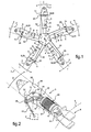
- a rotorcraft rotor comprises a rotating hub 1 on which blades 2 are mounted for their rotational drive.
- the blades 2 are radially distributed on the hub 1, being assembled to the hub 1 by means of respective sleeves 3.
- the blades are individually carried by a sleeve 3 which is mounted to move on the hub 1 by means of junction means 4 articulated.
- connection means 4 advantageously use a spherical abutment member 5, as illustrated in FIG. fig.9 .
- the blades 2 are secured to the sleeve 3 which is assigned to them, by assembling their blade root to the sleeve 3.
- the blades 2 are capable of being integral with the sleeves 3 by integration.
- the blades 2 are subjected to oscillations in drag T that it is necessary to dampen.
- drag oscillations T are caused around a pivot axis in dragging sleeves on the hub.
- Such a trailing pivot axis is substantially parallel to the axis A of rotation of the hub 1.
- the rotor is equipped with a damping device, comprising in general dampers 6 interposed between the sleeves 3 and the gripping members 7 to the hub 1, either directly or indirectly via a blade 2.
- the respective architectures mounting shock absorbers 6 on the rotor are similar from one to the other. other shock absorbers 6.
- the damper 6 is engaged at opposite fixing points 8,9 respectively on a sleeve 3 which houses it and on a gripping member 7 at the hub 1.
- the damper 6 is an elastically deformable member between said fixing points 8,9, and is potentially of cylindrical conformation while working in torsion, or of elongated conformation by working in tension / compression as illustrated in the figures.
- a distal fixing point 9 of each of the dampers 6 is articulated on a first end of a linkage 10.
- Each linkage 10 is also articulated on a said engagement member 7 which is assigned to a second end of the crank 10 opposed to its first end.
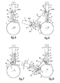
- the linkages 10 are articulated on the hub 1 either directly, as illustrated on the fig.1 , fig.5 and fig.7 , or indirectly as illustrated in the fig.3, fig.4 , fig.6 and fig.8 .
- the indirect connection of the linkages 10 on the hub 1 is in particular carried out by means of adjacent sleeves 3 to the sleeve 3 housing a damper 6 in articulated engagement on a linkage 10 considered.
- the linkages 10 are likely to comprise a single connecting rod, as illustrated in FIGS. fig.1 , fig.3 and fig.5 to fig.8 , or to understand several rods articulated between them as illustrated on the fig.4 .
- the rod or rods are considered in their generality as elements of mechanical transmission of forces, from which transmission elements are configured various potential architectures of linkages 10 between their ends.
- the linkages 10 may comprise various transmission elements, in particular not only one or more connecting rods, but also other elements for mechanical transmission of forces such as lever arms, or even additional dampers interposed on the architecture of the linkages 10 considered between their ends.
- linkages 10 are likely to be implemented according to the drag damping requirements of the blades 2, such needs being dependent on the general structure of the rotor and / or the characteristics of the rotorcraft equipped with such a rotor.
- the sleeves 3 each individually house a damper 6, this damper 6 being in articulated engagement on a linkage 10 via a lever arm 11.
- the lever arm 11 is itself articulated on the sleeve 3 housing this damper 6, in particular pivoting. It is remarkable that each shock absorber 6 is articulated to each of its attachment points 8.9 on the sleeve 3 which houses it.
- the distal fixation point 9 of the damper 6 is articulated by means of a said lever arm 11 at a time on a linkage 10 and on the sleeve 3 housing the damper 6.
- the proximal fixation point 8 of the damper 6 is as to him articulated on the sleeve 3, either directly or more marginally via the hub 1 as illustrated on the fig.9 .
- any sleeve 3 of the rotor houses a damper 6 which is in articulated engagement with its proximal attachment point 8 on the hub 1.
- a spherical abutment member 5 is interposed between the hub 1 and the sleeve 3 for their articulated joint. one to another. It is used a mounting structure 12 of the spherical abutment member 5 on the hub 1 to articulate the damper 6 on the hub 1.
- the hub 1 is provided with a hinge member 13 of the attachment point proximal of the damper 6 on the hub 1, such as for example a yoke. Such a hinge member 13 is advantageously easily integrated with said mounting structure 12.
- the lever arms 11 each comprise and for a given lever arm a hinge socket 23 preferably pivoting the lever arm on said sleeve 3, an articulation socket 24 potentially in ball but preferably in pivoting of the point of articulation.
- the lever arms 11 are adapted to be variously arranged according to the damping requirements of the oscillations of the blades 2 drag.
- the lever arms 11 constitute not only an articulation member of the dampers 6 on the sleeve 3 which houses them individually, but also a force transmission member interposed between a linkage 10 and a damper 6.
- the structural characteristics of a such force transmission member arranged as a lever arm 11 are easily adaptable to vary as required the conditions of biasing the damper 6.
- lever arms 11 are mechanical force transmission members whose structural characteristics and whose articulation points of the linkages 10 and dampers 6 respectively assigned to these lever arms 11, can be easily adapted according to the desired conditions for biasing the damper to dampen drag oscillations of the blades of any rotor fitted to any rotorcraft.
- each lever arm 11 is likely to be rectilinear in conformation with branches arranged in the extension of one another, as shown in FIG. fig.10 , or to include branches 14,15 concurrent forming dihedral, and more particularly in the form of a bow or elbow for example, as shown in FIG. fig.11 .
- Each lever arm 11 has three hinge zones 16, 17, 18.
- a medial articulation area 17 is for example assigned to the articulation of the lever arm 11 on the sleeve 3.
- the two other areas of articulation 16 and 18 are arranged on either side of the central articulation zone 17, at the end of the branches 14,15 forming the lever arm 11.
- the said other hinge areas 16 and 18 are for example respectively assigned to the articulation of a damper 6 on the lever arm 11, and to the articulation of a linkage 10 on the lever arm 11.
- these hinge areas 16,17,18 are likely to be variously affected to one or the other of said joints.
- the distances d1, d2 and d3 of separation of the different 16,17,18 articulation areas of each other are adaptable, to vary the implementation characteristics of the lever arm 11 as required.
- the sleeve 3 comprises a wall forming a casing 19 for confining the damper 6.
- a casing 19 advantageously delimits the internal recess of the sleeve 3.
- the casing 19 comprises a window 22 of emergence of the lever arm 11 out of the sleeve 3, to allow articulated engagement of the linkage assembly 10 to the lever arm 11.
- cooling means are advantageously used to cool the damper 6.
- cooling means comprise forced air passages 20 formed through the 19.
- forced air passages 20 may be completed by a finned heat exchanger 21 implanted or integrated in the body of the damper 6.
Abstract
Description
La présente invention est du domaine des rotors de giravions, et relève plus particulièrement des dispositifs d'amortissement des mouvements de pales équipant de tels rotors.The present invention is in the field of rotorcraft rotors, and more particularly falls damping devices blade movements equipping such rotors.
La présente invention a pour objet un dispositif d'amortissement des oscillations en traînée des pales d'un rotor de giravion. La présente invention porte plus spécifiquement sur les modalités de montage sur un moyeu du rotor, d'un amortisseur que comprend un tel dispositif d'amortissement.The present invention relates to a device for damping drag oscillations of the blades of a rotorcraft rotor. The present invention relates more specifically to the mounting method on a hub of the rotor, a damper that includes such a damping device.
Les giravions sont des aéronefs à voilure tournante, parmi lesquels sont classifiés les hélicoptères. Un hélicoptère comporte notamment au moins un rotor principal à axe sensiblement vertical, procurant la sustentation, la propulsion et le guidage du giravion en vol. L'hélicoptère comporte aussi couramment un rotor arrière pour son guidage en lacet, voire encore une hélice propulsive dans le cadre d'un hélicoptère à grandes vitesses et à longue portée, communément désigné par hélicoptère hybride.Rotorcraft are rotary wing aircraft, of which helicopters are classified. A helicopter comprises in particular at least one main rotor with a substantially vertical axis, providing lift, propulsion and guiding the rotorcraft in flight. The helicopter also commonly includes a tail rotor for its yaw steering, or even a propellant propeller in a high-speed, long-range helicopter, commonly referred to as a hybrid helicopter.
Un rotor de giravion comporte un moyeu tournant entraîné en rotation par une source motrice du giravion, sur lequel moyeu sont montées des pales pour leur entraînement en rotation par le moyeu. Les pales sont montées mobiles sur le moyeu en pivotement sur elles-mêmes dans leur plan général d'extension, pour permettre de faire varier leur pas au moins collectivement, tel que pour un rotor arrière ou une hélice propulsive, sinon aussi cycliquement pour un rotor principal notamment. Une variation de pas collectif ou cyclique des pales d'un rotor permet de modifier le comportement en vol du giravion.A rotorcraft rotor comprises a rotating hub driven in rotation by a rotorcraft power source, on which hub are mounted blades for their rotational drive by the hub. The blades are movably mounted on the hub pivoting on themselves in their general plane of extension, to allow to vary their pitch at least collectively, such as for a rear rotor or a propeller propeller, if not also cyclically for a rotor principal, in particular. A collective or cyclic variation of the blades of a rotor makes it possible to modify the flight behavior of the rotorcraft.
Il est courant de monter les pales sur le moyeu par l'intermédiaire d'organes de liaison, tel qu'agencés en bras, en manchon ou autre organe analogue de montage d'une pale sur le moyeu. Un tel organe de liaison, désigné ci-après par manchon, est interposé entre le pied d'une pale et le moyeu. Pour autoriser les dites variations de pas des pales, les manchons sont articulés sur le moyeu, tel que par exemple au moyen d'un organe de butée sphérique, et sont manoeuvrables en pivotement par une tringle de commande de variation du pas des pales.It is common to mount the blades on the hub by means of connecting members, as arranged in arms, sleeve or other similar member for mounting a blade on the hub. Such a connecting member, hereinafter referred to as a sleeve, is interposed between the base of a blade and the hub. To allow said pitch variations of the blades, the sleeves are hinged to the hub, such as for example by means of a spherical abutment member, and are pivotally operable by a pitch control rod of the pitch of the blades.
Les pales étant entraînées en rotation par le moyeu et étant mobiles dans leur plan général pour faire varier leur pas, leur comportement individuel est réputé complexe, particulièrement pour les pales du rotor principal.The blades being rotated by the hub and being movable in their general plane to vary their pitch, their individual behavior is deemed complex, particularly for the blades of the main rotor.
En effet, il est à considérer que les pales sont soumises en rotation à des efforts qui varient sur leur longueur. En situation de vol stationnaire ou d'avancement du giravion, la répartition des efforts aérodynamiques le long d'une pale engendre une répartition de moment de flexion, dont la valeur est très importante en pied de pale. En progression du giravion en translation, la pale « avançante » a une incidence (ou pas) plus faible que la pale « reculante » dont le pas est augmenté afin d'équilibrer les portances.Indeed, it is to be considered that the blades are subjected to rotation forces that vary over their length. In a situation of hovering or advancing of the rotorcraft, the distribution of the aerodynamic forces along a blade generates a bending moment distribution, the value of which is very important at the foot of the blade. In progression of the rotorcraft in translation, the "advancing" blade has an incidence (or not) lower than the "recoiling" blade whose step is increased in order to balance the lift.
Il a donc été proposé d'articuler les pales sur le moyeu en battement vertical autour d'un axe de battement orienté orthogonalement à l'axe de rotation du moyeu. Lors de la mise en rotation de la voilure tournante, la composition de la force centrifuge et des efforts de portance induit un basculement des pales en battement vertical, conférant à la voilure tournante une certaine conicité, le plan de rotation des pales pouvant être différent du plan orthogonal à l'axe de rotation du moyeu. Il est aussi à prendre en compte dans le montage de la pale sur le moyeu, une faculté d'escamotage de la pale en position de repli de la voilure tournante.It has therefore been proposed to articulate the blades on the hub in vertical beat around a beat axis oriented orthogonal to the axis of rotation of the hub. During the rotation of the rotary wing, the composition of the centrifugal force and the lift forces induces a tilting of the blades in vertical flapping, conferring on the rotary wing a certain taper, the plane of rotation of the blades being different from the plane orthogonal to the axis of rotation of the hub. It is also to be taken into account in the mounting of the blade on the hub, a faculty of retraction of the blade in the retracted position of the rotary wing.
Dans ce contexte, il est encore à considérer que les pales sont en outre articulées en traînée sur le moyeu dans leur plan de rotation, autour d'un axe de traînée orienté sensiblement parallèlement à l'axe de rotation du moyeu. Une telle articulation des pales en traînée permet d'éviter la génération de moments de flexion des pales dans leur plan.In this context, it is still to be considered that the blades are further articulated in drag on the hub in their plane of rotation, about a drag axis oriented substantially parallel to the axis of rotation of the hub. Such articulation of the blades in drag avoids the generation of bending moments of the blades in their plane.
Cependant, les oscillations individuelles des pales autour de leur axe de traînée sont à l'origine d'un phénomène connu de résonnance au sol du giravion. Un tel phénomène est réputé potentiellement dangereux lorsque la fréquence propre d'oscillation des pales autour de l'axe de traînée est proche d'une fréquence propre de l'appareil au sol. Un tel problème est notamment posé pour le rotor principal, mais doit aussi être pris en compte pour d'autres voilures tournantes équipant l'hélicoptère, telles que pour le rotor arrière pour lequel il doit être pris en considération les modes propres d'oscillation d'une poutre de queue porteuse du rotor arrière.However, the individual oscillations of the blades around their drag axis are at the origin of a known phenomenon of ground resonance of the rotorcraft. Such a phenomenon is considered potentially dangerous when the natural frequency of oscillation of the blades around the axis of drag is close to a natural frequency of the ground device. Such a problem is notably posed for the main rotor, but must also be taken into account for other rotating wings equipping the helicopter, such as for the rear rotor for which it must be taken into account the natural modes of oscillation of the helicopter. a tail boom carrying the tail rotor.
Pour remédier à ce problème, il est connu d'équiper les rotors d'un dispositif d'amortissement des oscillations en traînée des pales autour de leur axe de traînée. Il a notamment été développé divers dispositifs d'amortissement, mettant en oeuvre des amortisseurs à déformation élastique. Chaque amortisseur est en prise articulée sur un organe de prise au moyeu par l'intermédiaire d'un embiellage, et sur une pale affectée à cet amortisseur. L'embiellage comprend notamment une ou plusieurs bielles, ou autres éléments analogues de transmission mécanique d'efforts.To remedy this problem, it is known to equip the rotors with a device for damping drag oscillations of the blades around their drag axis. In particular, various damping devices have been developed, using shock absorbers with elastic deformation. Each damper is articulated on a hub engaging member by means of a linkage, and on a blade assigned to this damper. The linkage comprises in particular one or more connecting rods, or other similar elements of mechanical transmission of forces.
Il est notamment exploité une faculté de déformation élastique de l'amortisseur entre deux points de fixation, pour amortir les oscillations en traînée d'au moins une pale qui lui est affectée. L'amortisseur est placé sous contraintes en déformation élastique entre lesdits points de fixation. L'un des points de fixation de l'amortisseur, considéré comme distal, est ancré par l'intermédiaire de l'embiellage sur un organe de prise au moyeu. L'autre des dits points de fixation de l'amortisseur, considéré comme proximal, est en prise sur une dite pale qui lui est affectée.It is particularly exploited a faculty of elastic deformation of the damper between two attachment points, to damp the drag oscillations of at least one blade assigned to it. The damper is placed under stress in elastic deformation between said attachment points. One of the attachment points of the damper, considered distal, is anchored via of the linkage on a hub engaging member. The other of said attachment points of the damper, considered proximal, is engaged on a said blade which is assigned to it.
Selon diverses architectures possibles, l'organe de prise de l'amortisseur au moyeu est ménagé sur une pale voisine ou est incorporé au moyeu. La prise de l'amortisseur à son point de fixation proximal sur une dite pale qui lui est affectée, est potentiellement réalisée sur le manchon porteur de cette pale. Toujours selon diverses configurations possibles plus ou moins complexes visant à procurer des sollicitations de l'amortisseur adaptées aux besoins, le point de fixation distal de l'amortisseur, voire aussi son point de fixation proximal, sont en prise articulée sur une bielle. Une telle bielle est elle-même potentiellement articulée sur d'autres bielles articulées entre elles et/ou sur le moyeu et/ou encore sur le manchon d'une pale.According to various possible architectures, the damper engaging member hub is formed on a neighboring blade or is incorporated in the hub. The taking of the damper at its proximal fixation point on a said blade which is assigned to it, is potentially performed on the bearing sleeve of this blade. Still according to various more or less complex possible configurations designed to provide shock absorber stresses adapted to the needs, the distal fixation point of the shock absorber, or even its proximal attachment point, are articulated on a connecting rod. Such a rod is itself potentially articulated on other rods hinged together and / or on the hub and / or on the sleeve of a blade.
Les amortisseurs utilisés sont susceptibles d'être diversement agencés. Par exemple, les amortisseurs sont de conformation allongée et travaillent en traction/compression, ou sont de conformation cylindrique et travaillent en torsion. Un amortisseur de conformation cylindrique présente l'avantage d'être d'un agencement ramassé et peu encombrant, et finalement présente l'avantage d'être facilement implantable sur un manchon exploité pour la jonction de la pale au moyeu.The dampers used are likely to be variously arranged. For example, the dampers are of elongated conformation and work in tension / compression, or are of cylindrical conformation and work in torsion. A cylindrical conformation damper has the advantage of being of a compact and space-saving arrangement, and finally has the advantage of being easily implantable on a sleeve used for joining the blade to the hub.
Il a par exemple été proposé par le document
On pourra par exemple encore se reporter aux documents
Il est apparu qu'une implantation des amortisseurs à l'intérieur des manchons, telle que divulguée par le document
Cependant, il est aussi apparu qu'une implantation des amortisseurs à l'intérieur des manchons est facilitée dans le cas d'un amortisseur de conformation cylindrique. En effet, un tel amortisseur peut être facilement ancré à l'intérieur du manchon et être mis en prise articulée sur le moyeu par l'intermédiaire d'une dite bielle. Une telle implantation est plus délicate à réaliser pour un amortisseur de quelconque agencement.However, it has also been found that implantation of the dampers inside the sleeves is facilitated in the case of a cylindrical conformal damper. Indeed, such a damper can be easily anchored inside the sleeve and be articulated on the hub via a said rod. Such an implantation is more difficult to achieve for a damper of any arrangement.
Il est ainsi constaté que la solution proposée par le document
En effet tel que précédemment mentionné, les besoins d'amortissement des oscillations en traînée des pales sont étroitement liés aux dits phénomènes de résonnance, et donc à la puissance et à la structure propre du giravion. Il est opportun que l'implantation de l'amortisseur dans le manchon ne fasse pas obstacle à une optimisation des configurations possibles d'implantation sur le rotor des autres organes que comprend le dispositif d'amortissement. Il serait avantageux que diverses architectures de l'embiellage adaptées à des besoins spécifiques d'amortissement des oscillations des pales en traînée soient rendues possibles sans modification structurelle majeure du dispositif d'amortissement.Indeed, as previously mentioned, the damping requirements of drag oscillations of the blades are closely related to said resonance phenomena, and therefore to the power and structure of the rotorcraft. It is appropriate that the implantation of the damper in the sleeve does not hinder an optimization of the possible configurations of implantation on the rotor of other organs that includes the damping device. It would be advantageous if various architectures of the linkage adapted to specific needs for damping oscillations of the drag blades are made possible without major structural modification of the damping device.
Il est ainsi à considérer que l'un des buts de la présente invention est de procurer une liberté d'agencement du dispositif d'amortissement en fonction des besoins spécifiques d'un rotor, à partir d'une adaptation aisée de l'organisation générale d'un dispositif d'amortissement fondamental aisément modulable.It is thus to be considered that one of the aims of the present invention is to provide a freedom of arrangement of the damping device according to the specific needs of a rotor, from an easy adaptation of the general organization. a fundamental damping device that can be easily modulated.
Il est aussi recherché par la présente invention de bénéficier préférentiellement des avantages que procure une implantation des amortisseurs à l'intérieur des manchons ou organes de liaison analogues aptes à protéger les amortisseurs de l'environnement extérieur. Un choix de la présente invention est de limiter les traînées aérodynamiques générées par le dispositif d'amortissement, et de préserver au mieux les amortisseurs de l'environnement hostile du rotor.It is also sought by the present invention to preferentially benefit from the advantages afforded by implantation of the dampers inside the sleeves or similar connecting members able to protect the dampers from the external environment. A choice of the present invention is to limit the aerodynamic drag generated by the damping device, and to better preserve the dampers of the harsh environment of the rotor.
A partir de ce choix, il est aussi recherché par la présente invention de proposer un dispositif d'amortissement des oscillations en traînée des pales, qui soit exploitable par adaptation simple et sans modification structurelle majeure pour de quelconques giravions, quels que soient leur structure propre et les besoins spécifiques d'amortissement des oscillations en traînée des pales du ou des rotors dont ces quelconques giravions sont équipés.From this choice, it is also sought by the present invention to provide a device for damping drag oscillations of the blades, which is exploitable by simple adaptation and without major structural modification for any rotorcraft, whatever their specific structure. and the specific needs for damping the drag oscillations of the rotor blades or blades of which these rotorcraft are equipped.
Dans ce contexte, l'objet de la présente invention est de proposer un rotor de giravion équipé d'un dispositif d'amortissement des oscillations en traînée des pales de ce rotor, et un giravion équipé d'un tel rotor.In this context, the object of the present invention is to propose a rotorcraft rotor equipped with a damping device drag oscillations of the blades of this rotor, and a rotorcraft equipped with such a rotor.
Il est plus particulièrement visé par la présente invention de proposer un tel rotor, dans lequel le dispositif d'amortissement comporte des amortisseurs logés dans des manchons procurant une liaison entre des pales et un moyeu du rotor, en prenant en compte l'ensemble des avantages potentiels à bénéficier, et les contraintes et/ou difficultés à surmonter qui ont été énoncés.It is more particularly the object of the present invention to provide such a rotor, wherein the damping device comprises dampers housed in sleeves providing a connection between blades and a hub of the rotor, taking into account all the advantages. potential benefits, constraints and / or challenges that have been identified.
Le rotor de giravion de la présente invention est équipé d'un dispositif d'amortissement des oscillations en traînée des pales du rotor. Les pales sont individuellement montées articulées sur un moyeu tournant du rotor par l'intermédiaire de manchons respectifs. Les manchons sont chacun articulés sur le moyeu, au moins autour d'un axe de traînée orienté sensiblement parallèlement à l'axe de rotation du moyeu.The rotorcraft rotor of the present invention is equipped with a device for damping drag oscillations of the rotor blades. The blades are individually mounted articulated on a rotating hub of the rotor via respective sleeves. The sleeves are each articulated on the hub, at least about a drag axis oriented substantially parallel to the axis of rotation of the hub.
Le dispositif d'amortissement comprend un jeu d'amortisseurs, chacun individuellement logés dans un dit manchon. Il est à considérer que les manchons sont des organes de liaison entre la pale et le moyeu, sans préjuger de l'agencement spécifique d'un tel manchon. La qualification de manchon d'un tel organe de liaison ne doit pas être appréhendée au sens strict du terme selon une approche générale de la présente invention, dès lors que l'organe de liaison formé par un dit manchon est principalement apte à procurer le montage en mobilité de la pale au moyeu. Un tel organe de liaison ménage subsidiairement un logement avantageux de réception d'un dit amortisseur, permettant de le protéger de l'environnement hostile du rotor et de limiter les traînées aérodynamiques générées par le dispositif d'amortissement.The damping device comprises a set of dampers, each individually housed in a said sleeve. It is to be considered that the sleeves are connecting members between the blade and the hub, without prejudging the specific arrangement of such a sleeve. The qualification of a sleeve of such a connecting member must not be apprehended in the strict sense of the term according to a general approach of the present invention, since the connecting member formed by a said sleeve is mainly able to provide mounting in mobility from the blade to the hub. Such a connecting member alternatively provides an advantageous housing for receiving a said damper, to protect it from the harsh environment of the rotor and to limit the aerodynamic drag generated by the damping device.
Un choix est cependant préférentiellement porté sur un organe de liaison structurellement agencé en organe évidé tel qu'un manchon ou analogue. Un tel manchon ménage avantageusement dans son évidement intérieur une chambre axiale apte à recevoir divers organes fonctionnels. De tels organes fonctionnels sont potentiellement liés à la mobilité de la pale sur le moyeu, tel que par exemple un organe à butée sphérique interposé entre le manchon et le moyeu.However, a choice is preferably made on a connecting member structurally arranged hollow member such as a sleeve or the like. Such a sleeve advantageously provides in its internal recess an axial chamber adapted to receive various functional organs. Such functional members are potentially related to the mobility of the blade on the hub, such as for example a spherical stop member interposed between the sleeve and the hub.
Dans le cadre de la présente invention, une dite chambre axiale d'un manchon est avantageusement apte à loger un dit amortisseur sans avoir à doter l'organe de liaison d'un logement spécifique de réception de l'amortisseur. Il doit néanmoins être compris que l'amortisseur est susceptible d'être logé dans un quelconque logement du manchon ou de tout autre organe de liaison analogue entre la pale et le moyeu comportant un tel logement apte à recevoir un dit amortisseur, en vue de limiter les traînées aérodynamiques que l'amortisseur est susceptibles de générer, et de le protéger de l'environnement extérieur, notamment du milieu hostile que forme un rotor. Par exemple dans le cas d'une utilisation d'un bras de liaison entre la pale et le moyeu, un tel bras de liaison est susceptible de comporter un carter ou paroi analogue ménageant un logement de réception de l'amortisseur à la manière d'un manchon.In the context of the present invention, a said axial chamber of a sleeve is advantageously adapted to accommodate a said damper without having to provide the connecting member with a specific housing for receiving the damper. It should nevertheless be understood that the damper is capable of being housed in any housing of the sleeve or any other similar connecting member between the blade and the hub comprising such a housing adapted to receive a said damper, in order to limit aerodynamic drag that the damper is likely to generate, and protect it from the outside environment, including hostile environment that forms a rotor. For example, in the case of using a connecting arm between the blade and the hub, such a connecting arm is likely to include a casing or similar wall forming a housing for receiving the damper in the manner of a sleeve.
Chaque amortisseur est élastiquement déformable entre deux points de fixation, par l'intermédiaire desquels points de fixation l'amortisseur est placé sous contrainte entre le manchon qui le loge et un organe de prise au moyeu par l'intermédiaire d'un embiellage. Chaque amortisseur comporte, entre les moyens à déformation élastique qu'il intègre, des points de fixation opposés dont un point de fixation proximal et un point de fixation distal.Each damper is elastically deformable between two attachment points, through which points of attachment the damper is placed under stress between the sleeve which houses it and a hub member by means of a linkage. Each damper comprises, between the elastically deformable means that it incorporates, opposite attachment points including a proximal fixation point and a distal fixation point.
Ces points de fixation sont respectivement en prise articulée sur le manchon qui loge l'amortisseur et sur un dit organe de prise de l'amortisseur au moyeu par l'intermédiaire de l'embiellage. Dans ces conditions, il est à considérer diverses configurations selon lesquelles chaque amortisseur est placé sous contraintes en conséquence des oscillations en traînée au moins de la pale équipée du manchon logeant un amortisseur donné, sinon aussi des oscillations en traînée d'une pale voisine à cette pale, sur laquelle pale voisine ledit amortisseur donné est en prise par l'intermédiaire de l'embiellage.These attachment points are respectively in articulated engagement on the sleeve which houses the damper and on a said damper engaging member to the hub through the linkage. In these conditions, it is to consider various configurations according to which each damper is placed under stress as a result of oscillations in drag at least the blade equipped with the sleeve housing a given damper, if not also drag oscillations of a blade adjacent to this blade, on which the said adjacent damper damper is in taken through the linkage.
Selon la présente invention, un tel rotor de giravion est principalement reconnaissable en ce que pour chacun des manchons, l'amortisseur que loge un manchon donné est en prise articulée sur l'embiellage par l'intermédiaire d'un bras de levier articulé sur le manchon.According to the present invention, such a rotorcraft rotor is mainly recognizable in that for each of the sleeves, the damper housed by a given sleeve is articulated on the linkage by means of a lever arm hinged to the muff.
Les bras de levier dont les manchons sont individuellement équipés, sont des éléments de transmission d'efforts articulés sur les manchons, qui complètent les embiellages de liaison individuelle entre les amortisseurs et les organes de prise des embiellages au moyeu. Les conditions de mise sous contraintes et de sollicitations des amortisseurs sont aisément adaptables à partir d'une modification des positions relatives sur les bras de levier de l'articulation des bras de levier sur les manchons, de l'articulation des embiellages sur les bras de levier et de l'articulation des amortisseurs sur les bras de levier. Les conditions de mise sous contrainte et de sollicitations spécifiques des amortisseurs peuvent être ajustées selon les besoins en amortissement à procurer, à partir d'une dite adaptation aisée des bras de levier.The lever arms, whose sleeves are individually equipped, are articulated force transmission elements on the sleeves, which complete the individual linkages between the shock absorbers and the connecting members of the linkages to the hub. The stresses and stresses of the shock absorbers are easily adaptable from a modification of the relative positions on the lever arms of the articulation of the lever arms on the sleeves, the articulation of the links on the arms of lever and hinge dampers on the lever arms. The conditions of stressing and specific stresses of the dampers can be adjusted according to the depreciation needs to be provided, from a so-called easy adaptation of the lever arms.
En outre, les bras de levier sont des organes de raccordement intermédiaires entre les amortisseurs et les embiellages sur lesquels les amortisseurs sont respectivement en prise par l'intermédiaire des bras de levier. Les bras de levier sont préférentiellement articulés en pivotement sur le manchon, un tel raccordement intermédiaire entre les amortisseurs et les embiellages permettant d'éviter de faire supporter aux amortisseurs des efforts divergents de ceux visant à amortir les oscillations en traînée des pales. Chaque bras de levier est monté pivotant sur le manchon qui lui est affecté autour d'un axe de pivot préférentiellement parallèle à l'axe de traînée de la pale porté par ce manchon.In addition, the lever arms are intermediate connecting members between the dampers and the linkages on which the dampers are respectively engaged via the lever arms. The lever arms are preferably pivotally articulated on the sleeve, such an intermediate connection between the dampers and the linkages to avoid the shock absorbers to bear efforts divergent from those aimed at dampen the drag oscillations of the blades. Each lever arm is pivotally mounted on the sleeve which is assigned thereto around a pivot axis preferably parallel to the drag axis of the blade carried by this sleeve.
La structure générale du dispositif d'amortissement est aisément transposable à un quelconque rotor équipant un quelconque giravion. Le montage avantageux des amortisseurs logés dans les manchons ne fait pas obstacle à une exploitation du dispositif d'amortissement pour différents rotors dont les besoins d'amortissement des oscillations en traînée des pales sont spécifiques. Une telle exploitation diversifiée est obtenue sans modification structurelle majeure du dispositif d'amortissement, à partir d'une adaptation aisée à réaliser des bras de levier, et plus particulièrement une adaptation des dites positions relatives des diverses articulations entre elles sur les bras de levier.The general structure of the damping device is easily transferable to any rotor fitted to any rotorcraft. The advantageous mounting of the dampers housed in the sleeves does not preclude the operation of the damping device for different rotors whose damping requirements for drag oscillations of the blades are specific. Such a diversified exploitation is obtained without major structural modification of the damping device, from an easy adaptation to achieve lever arms, and more particularly an adaptation of said relative positions of the various joints between them on the lever arms.
La dite adaptation du bras de levier réside notamment dans une adaptation :
- ) de sa conformation générale et plus particulièrement de l'angle que forme potentiellement des branches du bras de levier sur lesquelles sont respectivement ménagés les diverses articulations,
- ) de la distance de séparation les unes des autres des différentes dites articulations,
- ) de la répartition sur le bras de levier du voisinage des dites articulations les unes par rapport aux autres.
- ) of its general conformation and more particularly of the angle that potentially forms branches of the lever arm on which are respectively formed the various articulations,
- ) of the separation distance from each other of the different said joints,
- ) of the distribution on the lever arm of the vicinity of said hinges relative to each other.
L'ajustement des conditions de travail des amortisseurs par l'intermédiaire de ladite adaptation des bras de levier, autorise l'exploitation d'amortisseurs qui peuvent être librement choisis selon les besoins en amortissement et/ou selon une configuration spécifique du rotor. Une telle liberté de choix est notamment relative aux capacités générales de déformation élastique des amortisseurs ou relative à la structure propre des amortisseurs, telle que pour des amortisseurs respectivement de conformation allongée ou de conformation cylindrique.The adjustment of the working conditions of the dampers by means of said adaptation of the lever arms, allows the operation of dampers which can be freely chosen according to the need for damping and / or according to a specific configuration of the rotor. Such freedom of choice is particularly the general capacity of elastic deformation of the dampers or relative to the own structure of the dampers, such as dampers respectively of elongated conformation or cylindrical conformation.
De surcroit, dans le cas d'une exploitation d'amortisseurs de conformation allongée, la position de l'articulation du bras de levier sur le manchon peut être plus ou moins éloignée par rapport à l'axe de pivot en traînée du manchon sur le moyeu. Plus particulièrement et selon les besoins pour un rotor donné, les positions respectives des points de fixation distal et proximal des amortisseurs par rapport à l'axe de pivot en traînée du manchon sur le moyeu peuvent être inversées. Plus particulièrement, les amortisseurs peuvent être avantageusement choisis de conformation allongée en étant notamment agencés en vérins. Par rapport à l'axe de pivot en traînée du manchon sur le moyeu, les positions des articulations respectivement du corps des vérins sur le manchon et du piston des vérins sur les bras de levier, peuvent être librement choisies l'une vis-à-vis de l'autre selon la position souhaitée de l'articulation des bras de levier sur le manchon.In addition, in the case of an elongated conformation damper operation, the position of the articulation of the lever arm on the sleeve may be more or less distant relative to the axis of pivot drag of the sleeve on the hub. More particularly and as needed for a given rotor, the respective positions of the distal and proximal attachment points of the dampers with respect to the drag pivot axis of the sleeve on the hub can be reversed. More particularly, the dampers may be advantageously chosen elongated conformation being in particular arranged in jacks. With respect to the axis of drag pivoting of the sleeve on the hub, the positions of the hinges respectively of the body of the jacks on the sleeve and the piston of the jacks on the lever arms, can be freely selected one vis-à- screw the other according to the desired position of the articulation of the lever arms on the sleeve.
L'ajustement des conditions de travail des amortisseurs à partir d'une adaptation des bras de levier permet aussi de mettre en relation des amortisseurs de structure donnée avec des embiellages de quelconques architectures, voire notamment permet de simplifier l'architecture de tels embiellages à partir de l'exploitation des caractéristiques de transmission d'effort procurées par les bras de levier et des caractéristiques propres des amortisseurs.The adjustment of the working conditions of the shock absorbers from an adaptation of the lever arms also makes it possible to relate the shock absorbers of given structure with linkages of any architectures, even in particular allows to simplify the architecture of such linkages from exploiting the power transmission characteristics provided by the lever arms and the specific characteristics of the dampers.
Plus particulièrement, les bras de levier équipant les manchons sont avantageusement des outils de réglage des caractéristiques d'amortissement des oscillations en traînée des pales par le dispositif d'amortissement, selon les positions relatives sur un bras de levier donné entre l'articulation du bras de levier sur le manchon, l'articulation de l'embiellage sur le bras de levier et l'articulation de l'un quelconque des points de fixation de l'amortisseur sur le bras de levier.More particularly, the lever arm equipping the sleeves are advantageously tools for adjusting the damping characteristics of the drag oscillations of the blades by the damping device, according to the relative positions on a given lever arm between the arm joint. lever on the sleeve, the articulation of the linkage on the lever arm and the articulation of any of the attachment points of the damper on the lever arm.
L'amortisseur logé dans un manchon donné est notamment en prise articulée à l'un quelconque de ses dits point de fixation sur l'embiellage par l'intermédiaire du bras de levier, ce point de fixation étant considéré comme un point de fixation distal. Cet amortisseur est notamment encore en prise articulée à l'autre de ses dits point de fixation sur le manchon, voire le cas échéant par l'intermédiaire du moyeu tel que visé ci-après, ce point de fixation étant considéré comme un point de fixation proximal.The damper housed in a given sleeve is in particular articulated to any of its said point of attachment to the linkage via the lever arm, this attachment point being considered as a distal attachment point. This damper is in particular still in articulated engagement with the other of its so-called attachment point on the sleeve, or even possibly through the hub as referred to below, this fixing point being considered as a point of attachment proximal.
Plus particulièrement, l'amortisseur logé dans un manchon donné est en prise articulée sur le manchon qui le loge à un dit point de fixation, considéré comme proximal. Ce point de fixation proximal est en prise indifféremment directement sur ce manchon ou indirectement par l'intermédiaire d'une structure du moyeu exploitée pour le montage de ce manchon au moyeu.More particularly, the damper housed in a given sleeve is articulated on the sleeve which houses it at a said point of attachment, considered proximal. This proximal fixation point is engaged either directly on this sleeve or indirectly via a structure of the hub used for mounting the sleeve to the hub.
Selon une forme préférée de réalisation, pour chacun des manchons et au regard d'un manchon donné, l'embiellage est articulé en rotule sur le bras de levier et le bras de levier est articulé en pivot sur le manchon. L'amortisseur quant à lui est articulé indifféremment en pivot ou en rotule en ses points de fixation respectivement sur le bras de levier et sur le manchon, le cas échéant par l'intermédiaire du moyeu.According to a preferred embodiment, for each of the sleeves and with respect to a given sleeve, the linkage is hinged to the ball on the lever arm and the lever arm is pivotally articulated on the sleeve. The damper meanwhile is articulated indifferently pivot or ball joint at its attachment points respectively on the lever arm and on the sleeve, if necessary via the hub.
Plus spécifiquement et selon une forme avantageuse de réalisation, les manchons sont individuellement montés sur le moyeu par l'intermédiaire d'organes à butée sphérique respectifs. Dans ce cas, l'amortisseur logé dans un manchon donné est éventuellement placé en prise articulée sur ce manchon par l'intermédiaire d'une structure de montage de l'organe à butée sphérique sur le moyeu, par exemple par l'intermédiaire d'une chape d'articulation au moyeu du point de fixation proximal de l'amortisseur. Les efforts auxquels sont soumis les amortisseurs sont avantageusement supportés par le moyeu, en préservant les manchons.More specifically and according to an advantageous embodiment, the sleeves are individually mounted on the hub by means of respective spherical stop members. In this case, the damper housed in a given sleeve is possibly placed in articulated engagement on this sleeve by means of a mounting structure of the spherical abutment member on the hub, by example by means of a hinge yoke at the hub of the proximal attachment point of the damper. The forces to which the dampers are subjected are advantageously supported by the hub, preserving the sleeves.
Selon divers agencement potentiels du bras de levier, le bras de levier est par exemple de conformation générale rectiligne ou par exemple encore de conformation générale en dièdre ou par analogie arquée. Le dièdre est notamment défini par un couple de branches composant le bras de levier.According to various potential arrangements of the lever arm, the lever arm is for example of generally rectilinear conformation or for example still of general conformation dihedron or arcuate analogy. The dihedral is defined in particular by a pair of branches forming the lever arm.
Selon une forme de réalisation selon laquelle le bras de levier est conformé en dièdre, l'embiellage et l'amortisseur sont de préférence respectivement articulés aux extrémités libres des branches, la zone de jonction rigide des branches l'une à l'autre étant exploitée pour ménager l'articulation du bras de levier sur le manchon.According to an embodiment according to which the lever arm is shaped as a dihedron, the linkage and the damper are preferably articulated respectively at the free ends of the branches, the rigid junction zone of the branches being used together. to arrange the articulation of the lever arm on the sleeve.
Selon différentes configurations alternatives possibles :
- ) l'articulation de l'amortisseur et l'articulation de l'embiellage sur le bras de levier sont disposées de part et d'autre de l'articulation du bras de levier sur le manchon.
- ) l'articulation du bras de levier sur le manchon est disposée à une extrémité du bras de levier, l'articulation de l'amortisseur et l'articulation de l'embiellage sur le bras de levier étant disposées à l'autre extrémité du bras de levier.
- ) l'articulation de l'embiellage sur le bras de levier est disposée entre l'articulation du bras de levier sur le manchon et l'articulation de l'amortisseur sur le bras de levier.
- ) the articulation of the damper and the articulation of the linkage on the lever arm are arranged on either side of the articulation of the lever arm on the sleeve.
- ) the articulation of the lever arm on the sleeve is disposed at one end of the lever arm, the articulation of the damper and the articulation of the linkage on the lever arm being arranged at the other end of the arm of leverage.
- ) the articulation of the linkage on the lever arm is disposed between the articulation of the lever arm on the sleeve and the articulation of the damper on the lever arm.
L'amortisseur est susceptible d'être indifféremment un amortisseur cylindrique à amortissement par torsion ou un amortisseur allongé à amortissement par traction/compression.The damper is likely to be indifferently a torsion damping cylindrical damper or an elongated damper damping by traction / compression.
Dans le cas où l'amortisseur est un amortisseur allongé étendu à l'intérieur du manchon suivant sa direction générale d'extension, l'une quelconque de ses extrémités considérée comme distale est articulée sur le bras de levier, l'autre de ses extrémités considérée comme proximale étant indifféremment directement articulée sur le manchon ou sur le moyeu considéré comme un organe intermédiaire entre le manchon et le point de fixation proximal de l'amortisseur.In the case where the damper is an elongate damper extended inside the sleeve in its general direction of extension, any of its ends considered distal is articulated on the lever arm, the other of its ends. considered proximal being indifferently directly articulated on the sleeve or on the hub considered as an intermediate member between the sleeve and the proximal point of attachment of the damper.
Il est cependant préféré d'articuler l'amortisseur au manchon, en son fond proche du moyeu notamment, pour permettre un montage de l'amortisseur articulé en pivotement à chacune de ses extrémités respectivement sur le bras de levier et sur le manchon, et/ou pour permettre une articulation en pivotement du bras de levier sur le manchon. Dans le cas où le point de fixation proximal de chacun des amortisseurs est articulé directement du le moyeu, une telle articulation est du type à rotule pour autoriser les divers mouvements nécessaires du manchon par rapport au moyeu.However, it is preferred to articulate the damper to the sleeve, in its bottom close to the hub in particular, to allow mounting of the articulated damper pivotally at each of its ends respectively on the lever arm and on the sleeve, and / or to allow pivoting articulation of the lever arm on the sleeve. In the case where the proximal attachment point of each of the dampers is articulated directly from the hub, such a joint is of the ball type to allow the various movements required of the sleeve relative to the hub.
Les modalités de montage de l'amortisseur à l'intérieur du manchon qui le loge, permettent une exploitation avantageuse d'un amortisseur de conformation allongée. La structure et les caractéristiques de fonctionnement de tels amortisseurs leurs confèrent une fiabilité et une pérennité avantageuses, et permettent de régler aisément les conditions spécifiques de leurs sollicitations propres à amortir les oscillations en traînée des pales. De tels amortisseurs allongés sont aisément transposables selon leurs caractéristiques d'un quelconque rotor à un autre quelconque rotor selon les besoins. En outre, le montage articulé à l'intérieur des manchons de tels amortisseurs allongés est facilité.The manner of mounting the damper inside the sleeve which houses it, allows an advantageous exploitation of an elongated conformal damper. The structure and the operating characteristics of such dampers give them an advantageous reliability and durability, and make it possible to easily adjust the specific conditions of their solicitations suitable for damping drag oscillations of the blades. Such elongated dampers are easily transferable according to their characteristics from any rotor to any other rotor as needed. In addition, the hinged mounting inside the sleeves of such elongated dampers is facilitated.
Le manchon est agencé en enveloppe de confinement de l'amortisseur et de logement du bras de levier. Ladite enveloppe comporte à son travers une fenêtre de passage d'une branche du bras de levier sur laquelle est articulé l'embiellage.The sleeve is arranged in the containment envelope of the damper and housing of the lever arm. Said envelope comprises through it a passage window of a branch of the lever arm on which is articulated the linkage.
Les agencements potentiels des manchons sont susceptibles d'être divers, dès lors qu'un tel manchon ménage avantageusement une enveloppe formant un bouclier aérodynamique masquant et/ou abritant l'amortisseur qu'il reçoit. Les manchons à évidement intérieur permettent de confiner aisément les amortisseurs, en limitant l'encombrement et sans porter atteinte à l'aisance de l'adaptation du dispositif d'amortissement pour un quelconque rotor d'un quelconque giravion. Chaque manchon loge un amortisseur et la quasi-totalité du bras de levier sur lequel cet amortisseur est en prise articulée, à l'exception d'une partie d'émergence du bras de levier hors de ladite enveloppe pour sa mise en prise articulée avec l'embiellage. Une telle partie d'émergence du bras de levier est potentiellement restreinte à une extrémité de l'une de ses branches sur laquelle est articulé l'embiellage.The potential arrangements of the sleeves are likely to be diverse, since such a sleeve advantageously provides an envelope forming a masking aerodynamic shield and / or sheltering the damper that it receives. The inner recess sleeves can easily confine the dampers, limiting the size and without compromising the ease of adaptation of the damping device for any rotor of any rotorcraft. Each sleeve houses a damper and substantially all of the lever arm on which this damper is in articulated engagement, except for an emergence portion of the lever arm out of said casing for articulated engagement with the casing. crankshaft. Such emergence portion of the lever arm is potentially restricted to one end of one of its branches on which is articulated the linkage.
Chaque manchon comporte de préférence des moyens de refroidissement de l'amortisseur qu'il loge. Les amortisseurs étant avantageusement logés à l'intérieur des manchons, de tels moyens de refroidissement sont susceptibles d'être exploités et d'être aisément organisés en fonction des conditions de travail spécifiques des amortisseurs.Each sleeve preferably comprises means for cooling the damper that it houses. The dampers being advantageously housed inside the sleeves, such cooling means are likely to be exploited and to be easily organized according to the specific working conditions of the dampers.
De tels moyens de refroidissement peuvent être aisément implantés sur les manchons, en étant par exemple agencés au moins en passages d'air forcé ménagés à travers la paroi des manchons délimitant ladite enveloppe. L'efficacité du refroidissement des amortisseurs par admission de flux d'air à l'intérieur des manchons est au besoin complétée par l'implantation, voire l'intégration, d'échangeurs de chaleur à ailettes ou analogues sur le corps des amortisseurs.Such cooling means can be easily implanted on the sleeves, for example being arranged at least in forced air passages formed through the wall of the sleeves defining said envelope. The effectiveness of the cooling of the dampers by admission of air flow inside the sleeves is, if necessary, supplemented by the implantation, or even the integration, finned heat exchangers or the like on the body of the dampers.
Plus particulièrement pour chacun des manchons et au regard d'un manchon donné, l'enveloppe formée par le manchon comporte à son travers au moins un passage d'air forcé de refroidissement de l'amortisseur.More particularly for each of the sleeves and with regard to a given sleeve, the casing formed by the sleeve comprises therethrough at least one forced air passage for cooling the damper.
Plus particulièrement encore pour chacun des manchons et au regard d'un manchon donné, un corps de l'amortisseur logé dans ce manchon est pourvu d'un échangeur de chaleur à ailettes.More particularly for each of the sleeves and with regard to a given sleeve, a body of the damper housed in this sleeve is provided with a finned heat exchanger.
Ledit organe de prise de l'embiellage au moyeu est notamment un organe d'attache indifféremment incorporé au moyeu ou à un manchon voisin du manchon logeant l'amortisseur en prise sur cet embiellage. L'embiellage est susceptible de comporter au moins un élément de transmission, sinon un jeu d'éléments de transmission articulés entre eux.Said coupling member of the hub hub is in particular a fastener indifferently incorporated in the hub or a sleeve adjacent the sleeve housing the damper engaged on this linkage. The linkage is likely to include at least one transmission element, otherwise a set of transmission elements hinged together.
Les avantages procurés par les bras de levier pour adapter les modalités de fonctionnement du dispositif d'amortissement selon les besoins, peuvent être aisément complétés par une libre adaptation de l'architecture des embiellages. Les embiellages sont susceptibles de comporter une ou plusieurs bielles articulées entre elles, voire encore des bras de levier interposés entre les bielles. A partir de mêmes modalités de montage des amortisseurs à l'intérieur des manchons par l'intermédiaire de bras de levier spécifiques, l'architecture de l'embiellage est aisément adaptable selon les besoins pour un rotor donné, voire peut être simplifiée.The advantages provided by the lever arms for adapting the operating modes of the damping device according to the needs can be easily complemented by a free adaptation of the architecture of the linkages. The linkages are likely to include one or more rods hinged together, or even lever arms interposed between the connecting rods. From the same mounting methods of the dampers inside the sleeves via specific lever arms, the architecture of the linkage is easily adaptable to the needs for a given rotor, or can be simplified.
La présente invention a aussi pour objet un giravion équipé d'un rotor tel qu'il vient d'être décrit.The present invention also relates to a rotorcraft equipped with a rotor as just described.
Des exemples de réalisation de la présente invention vont être décrits en relation avec les figures des planches annexées, dans lesquelles :
- la
fig.1 est une illustration partielle d'un rotor de giravion équipé d'un dispositif d'amortissement des oscillations en traînée des pales de ce rotor, selon un exemple de réalisation de la présente invention. - la
fig.2 est une illustration d'un manchon procurant une liaison entre une pale et un moyeu d'un rotor de giravion, logeant un amortisseur articulé sur ce manchon selon un autre exemple de réalisation de la présente invention. - les
fig.3 à fig.8 sont des illustrations partielles de rotors de giravion équipés de dispositifs d'amortissement selon des formes respectives de réalisation conformes à un rotor de la présente invention. - la
fig.9 est une représentation d'une extrémité proximale d'un manchon procurant une liaison entre une pale et un moyeu d'un rotor de giravion, selon un autre exemple de réalisation de la présente invention. - les
fig.10 et fig.11 sont des illustrations d'exemples respectifs de réalisation d'un bras de levier que comprend un dispositif d'amortissement équipant un rotor de la présente invention.
- the
fig.1 is a partial illustration of a rotorcraft rotor equipped with a device for damping the drag oscillations of the blades of this rotor, according to an exemplary embodiment of the present invention. - the
fig.2 is an illustration of a sleeve providing a connection between a blade and a hub of a rotorcraft rotor, housing a damper hinged to this sleeve according to another embodiment of the present invention. - the
fig.3 to fig.8 are partial illustrations of rotorcraft rotors equipped with damping devices according to respective embodiments according to a rotor of the present invention. - the
fig.9 is a representation of a proximal end of a sleeve providing a connection between a blade and a hub of a rotorcraft rotor, according to another embodiment of the present invention. - the
fig.10 and fig.11 are illustrations of respective embodiments of a lever arm that comprises a damping device fitted to a rotor of the present invention.
Sur les
Selon les exemples de réalisation illustrés, les pales 2 sont solidaires du manchon 3 qui leur est affecté, par assemblage de leur pied de pale au manchon 3. De manière analogue, les pales 2 sont susceptibles d'être solidaires des manchons 3 par intégration.According to the exemplary embodiments illustrated, the
En cours de rotation du rotor, les pales 2 sont soumises à des oscillations en traînée T qu'il est nécessaire d'amortir. De telles oscillations en traînée T sont provoquées autour d'un axe de pivot en traînée des manchons sur le moyeu. Un tel axe de pivot en traînée est sensiblement parallèle à l'axe A de rotation du moyeu 1. Pour amortir les oscillations en traînée T des pales 2, le rotor est équipé d'un dispositif d'amortissement, comprenant dans sa généralité des amortisseurs 6 interposés entre les manchons 3 et des organes de prise 7 au moyeu 1, soit directement soit indirectement par l'intermédiaire d'une pale 2. Les architectures respectives de montage des amortisseurs 6 sur le rotor sont similaires de l'un à l'autre des amortisseurs 6.During the rotation of the rotor, the
Pour chacun des amortisseurs 6, l'amortisseur 6 est en prise en des points de fixation 8,9 opposés respectivement sur un manchon 3 qui le loge et sur un organe de prise 7 au moyeu 1. L'amortisseur 6 est un organe élastiquement déformable entre ses dits points de fixation 8,9, et est potentiellement de conformation cylindrique en travaillant en torsion, ou de conformation allongée en travaillant en traction/compression tel qu'illustré sur les figures.For each of the
Plus particulièrement, un point de fixation distal 9 de chacun des amortisseurs 6 est en prise articulée sur une première extrémité d'un embiellage 10. Chaque embiellage 10 est par ailleurs en prise articulée sur un dit organe de prise 7 qui lui est affecté à une deuxième extrémité de l'embiellage 10 opposée à sa première extrémité. Les embiellages 10 sont en prise articulée sur le moyeu 1 soit directement, tel qu'illustré sur les
Selon diverses variantes de réalisation, les embiellages 10 sont susceptibles de comprendre une bielle unique, tel qu'illustré sur les
D'autres architectures d'agencement des embiellages 10 sont susceptibles d'être mises en oeuvre selon les besoins en amortissement en traînée des pales 2, de tels besoins étant dépendants de la structure générale du rotor et/ou des caractéristiques du giravion équipé d'un tel rotor.Other architecture arrangements of the
Les manchons 3 logent chacun individuellement un amortisseur 6, cet amortisseur 6 étant en prise articulée sur un embiellage 10 par l'intermédiaire d'un bras de levier 11. Le bras de levier 11 est lui-même articulé sur le manchon 3 logeant cet amortisseur 6, en pivotement notamment. Il est remarquable que chacun d'amortisseur 6 est en prise articulée à chacun de ses points de fixation 8,9 sur le manchon 3 qui le loge. En effet, le point de fixation distal 9 de l'amortisseur 6 est en prise articulée par l'intermédiaire d'un dit bras de levier 11 à la fois sur un embiellage 10 et sur le manchon 3 logeant cet amortisseur 6. Le point de fixation proximal 8 de l'amortisseur 6 est quant à lui en prise articulée sur le manchon 3, soit directement soit plus marginalement par l'intermédiaire du moyeu 1 tel qu'illustré sur la
Plus précisément sur la
Les bras de levier 11 comportent chacun et pour un bras de levier donné une prise d'articulation 23 de préférence en pivotement du bras de levier sur ledit manchon 3, une prise d'articulation 24 potentiellement en rotule mais de préférence en pivotement du point de fixation distal 9 de l'amortisseur 6 sur le bras de levier 11, et une prise d'articulation 25 en rotule de l'embiellage 10 sur le bras de levier 11.The
Les bras de levier 11 sont aptes à être diversement agencés selon les besoins d'amortissement des oscillations des pales 2 en traînée. Les bras de levier 11 constituent non seulement un organe d'articulation des amortisseurs 6 sur le manchon 3 qui les loge individuellement, mais aussi un organe de transmission d'efforts interposé entre un embiellage 10 et un amortisseur 6. Les caractéristiques structurelles d'un tel organe de transmission d'efforts agencé en bras de levier 11 sont facilement adaptables pour faire varier selon les besoins les conditions de sollicitation de l'amortisseur 6.The
Plus particulièrement, les bras de levier 11 sont des organes de transmission mécanique d'efforts, dont les caractéristiques structurelles et dont les points d'articulation des embiellages 10 et des amortisseurs 6 respectivement affectés à ces bras de levier 11, peuvent être facilement adaptés selon les conditions recherchées de sollicitation de l'amortisseur pour amortir les oscillations en traînée des pales d'un quelconque rotor équipant un quelconque giravion.More particularly, the
Par exemple, chaque bras de levier 11 est susceptible d'être de conformation rectiligne en comportant des branches disposées dans le prolongement l'une de l'autre, tel que représenté sur la
Chaque bras de levier 11 comporte trois zones d'articulations 16,17,18. Une zone d'articulation médiane 17 est par exemple affectée à l'articulation du bras de levier 11 sur le manchon 3. Les deux autres zones d'articulations 16 et 18 sont disposées de part et d'autre de la zone d'articulation médiane 17, en bout des branches 14,15 formant le bras de levier 11. Les dites autres zones d'articulation 16 et 18 sont par exemple respectivement affectées à l'articulation d'un amortisseur 6 sur le bras de levier 11, et à l'articulation d'un embiellage 10 sur le bras de levier 11.Each
Selon diverses variantes de réalisation fondées sur une recherche de sollicitations de l'amortisseur adaptées aux besoins, ces zones d'articulation 16,17,18 sont susceptibles d'être diversement affectées à l'une ou l'autre des dites articulations. Par ailleurs, les distances d1, d2 et d3 de séparation des différentes zones d'articulation 16,17,18 les unes des autres sont adaptables, pour faire varier les caractéristiques de mise en oeuvre du bras de levier 11 selon les besoins.According to various alternative embodiments based on a search for solicitations of the shock absorber adapted to the needs, these
Sur la
En cas de besoin selon les conditions de sollicitation de l'amortisseur 6, des moyens de refroidissement sont avantageusement exploités pour refroidir l'amortisseur 6. Par exemple, de tels moyens de refroidissement comprennent des passages d'air forcé 20 ménagés à travers l'enveloppe 19. De tels passages d'air forcé 20 sont susceptibles d'être complétés par un échangeur de chaleur à ailettes 21 implanté ou intégré au corps de l'amortisseur 6.If necessary according to the conditions of biasing the
Claims (20)
caractérisé en ce que pour chacun des manchons (3), l'amortisseur (6) que loge un manchon (3) donné est en prise articulée sur l'embiellage (10) par l'intermédiaire d'un bras de levier (11) articulé sur le manchon (3).Rotorcraft rotor equipped with a device for damping drag oscillations of the blades (2) of the rotor, the blades (2) being individually mounted articulated on a hub (1) rotating the rotor by means of sleeves (3) respective ones articulated on the hub (1), at least about a drag axis oriented substantially parallel to the axis of rotation ( A ) of the hub (1), the damping device comprising a set of dampers (6). ) each individually housed in a said sleeve (3), each damper (6) being elastically deformable between two attachment points (8, 9) through which attachment points (8, 9) the damper (6) is placed under stress between the sleeve (3) which houses it and a gripping member (7) at the hub (1) via a linkage (10),
characterized in that for each of the sleeves (3), the damper (6) housed by a sleeve (3) is articulated to the linkage (10) via a lever arm (11) articulated on the sleeve (3).
caractérisé en ce que les bras de levier (11) équipant les manchons (3) sont des outils de réglage des caractéristiques d'amortissement des oscillations en traînée des pales (2) par le dispositif d'amortissement, selon les positions relatives sur un bras de levier (11) donné entre l'articulation (23) du bras de levier (11) sur le manchon (3), l'articulation (25) de l'embiellage (10) sur le bras de levier (11) et l'articulation (24) de l'un quelconque des dits points de fixation (8,9) de l'amortisseur (6) sur le bras de levier (11).Rotorcraft rotor according to Claim 1,
characterized in that the lever arms (11) fitted to the sleeves (3) are tools for adjusting the damping characteristics of the drag oscillations of the blades (2) by the damping device, according to the relative positions on one arm lever (11) provided between the articulation (23) of the lever arm (11) on the sleeve (3), the articulation (25) of the linkage (10) on the lever arm (11) and the articulation (24) of any one of said attachment points (8, 9) of the damper (6) on the lever arm (11).
caractérisé en ce que l'amortisseur (6) logé dans un manchon (3) donné est en prise articulée à l'un quelconque de ses dits point de fixation (8,9) sur l'embiellage (10) par l'intermédiaire du bras de levier (11), et est en prise articulée à l'autre de ses dits point de fixation (8,9) sur le manchon (3).Rotorcraft rotor according to one of Claims 1 and 2,
characterized in that the damper (6) housed in a sleeve (3) is articulated to any one of said attachment points (8, 9) on the linkage (10) via the lever arm (11), and is in articulated engagement with the other of its so-called attachment point (8,9) on the sleeve (3).
caractérisé en ce que l'amortisseur (6) logé dans un manchon (3) donné est en prise articulée sur le manchon (3) qui le loge à un point de fixation proximal (8), indifféremment directement sur ce manchon (3) ou indirectement par l'intermédiaire d'une structure (12) du moyeu (1) exploitée pour le montage de ce manchon (3) au moyeu (1).Rotorcraft rotor according to one of Claims 1 to 3,
characterized in that the damper (6) housed in a sleeve (3) is articulated on the sleeve (3) which houses it at a proximal attachment point (8), either directly on the sleeve (3) or indirectly via a structure (12) of the hub (1) used for mounting this sleeve (3) to the hub (1).
caractérisé en ce que :
characterized in that
caractérisé en ce que les manchons (3) étant individuellement montés sur le moyeu (1) par l'intermédiaire d'organes à butée sphérique (5) respectifs, l'amortisseur (6) logé dans un manchon (3) donné est en prise articulée sur ce manchon (3) par l'intermédiaire d'une structure de montage (12) de l'organe à butée sphérique (5) sur le moyeu (1).Rotorcraft rotor according to one of Claims 1 to 5,
characterized in that the sleeves (3) being individually mounted on the hub (1) via respective spherical stop members (5), the damper (6) housed in a sleeve (3) is articulated socket on this sleeve (3) via a mounting structure (12) of the spherical stop member (5) on the hub (1).
caractérisé en ce que le bras de levier (11) est de conformation générale rectiligne.Rotorcraft rotor according to one of Claims 1 to 6,
characterized in that the lever arm (11) is of generally rectilinear conformation.
caractérisé en ce que le bras de levier (11) est de conformation générale en dièdre.Rotorcraft rotor according to one of Claims 1 to 6,
characterized in that the lever arm (11) is of generally dihedral conformation.
caractérisé en ce que l'articulation (24) de l'amortisseur (6) et l'articulation (25) de l'embiellage (10) sur le bras de levier (11) sont disposées de part et d'autre de l'articulation (23) du bras de levier (11) sur le manchon (3).Rotorcraft rotor according to one of Claims 1 to 8,
characterized in that the articulation (24) of the damper (6) and the articulation (25) of the linkage (10) on the lever arm (11) are arranged on either side of the articulation (23) of the lever arm (11) on the sleeve (3).
caractérisé en ce que l'articulation (23) du bras de levier (11) sur le manchon (3) est disposée à une extrémité du bras de levier (11), l'articulation (24) de l'amortisseur (6) et l'articulation (25) de l'embiellage (10) sur le bras de levier (11) étant disposées à l'autre extrémité du bras de levier (11).Rotorcraft rotor according to one of Claims 1 to 8,
characterized in that the hinge (23) of the lever arm (11) on the sleeve (3) is disposed at one end of the lever arm (11), the hinge (24) of the damper (6) and the articulation (25) of the linkage (10) on the lever arm (11) being arranged at the other end of the lever arm (11).
caractérisé en ce que l'articulation (25) de l'embiellage (10) sur le bras de levier (11) est disposée entre l'articulation (23) du bras de levier (11) sur le manchon (3) et l'articulation (24) de l'amortisseur (6) sur le bras de levier (11).Rotorcraft rotor according to one of Claims 1 to 8,
characterized in that the articulation (25) of the linkage (10) on the lever arm (11) is arranged between the articulation (23) of the lever arm (11) on the sleeve (3) and the articulation (24) of the damper (6) on the lever arm (11).
caractérisé en ce que l'amortisseur (6) est indifféremment un amortisseur cylindrique à amortissement par torsion ou un amortisseur allongé à amortissement par traction/compression.Rotorcraft rotor according to one of Claims 1 to 11,
characterized in that the damper (6) is indifferently a torsion damping cylindrical damper or an elongated shock absorber with compression / damping.
caractérisé en ce que l'amortisseur (6) étant un amortisseur allongé étendu à l'intérieur du manchon (3) suivant sa direction générale d'extension, l'une quelconque de ses extrémités considérée comme distale est articulée sur le bras de levier (11), l'autre de ses extrémités considérée comme proximale étant indifféremment articulée sur le manchon (3) ou sur le moyeu (1).Rotorcraft rotor according to one of Claims 1 to 12,
characterized in that the damper (6) being an elongate damper extended inside the sleeve (3) in its general direction of extension, any one of its ends considered distal is articulated on the lever arm ( 11), the other of its ends considered proximal being indifferently articulated on the sleeve (3) or on the hub (1).
caractérisé en ce que le manchon (3) est agencé en enveloppe (19) de confinement de l'amortisseur (6) et de logement du bras de levier (11), ladite enveloppe (19) comportant à son travers une fenêtre (22) de passage d'une branche du bras de levier (11) sur laquelle est articulée l'embiellage (10).Rotorcraft rotor according to one of Claims 1 to 13,
characterized in that the sleeve (3) is arranged as a casing (19) for confining the damper (6) and for housing the lever arm (11), said casing (19) comprising a window (22) therethrough passage of a branch of the lever arm (11) on which is articulated the linkage (10).
caractérisé en ce que le manchon (3) comporte des moyens de refroidissement de l'amortisseur.Rotorcraft rotor according to one of Claims 1 to 14,
characterized in that the sleeve (3) comprises cooling means of the damper.
caractérisé en ce que l'enveloppe (19) formée par le manchon (3) comporte à son travers au moins un passage d'air forcé (20) de refroidissement de l'amortisseur (6).Rotorcraft rotor according to claims 13 and 14,
characterized in that the casing (19) formed by the sleeve (3) has therethrough at least one forced air passage (20) for cooling the damper (6).
caractérisé en ce qu'un corps de l'amortisseur (6) est pourvu d'un échangeur de chaleur à ailettes (21).Rotorcraft rotor according to one of Claims 15 and 16,
characterized in that a body of the damper (6) is provided with a finned heat exchanger (21).
caractérisé en ce que ledit organe de prise (7) de l'embiellage (10) au moyeu (1) est un organe d'attache indifféremment incorporé au moyeu (1) ou à un manchon (3) voisin du manchon (3) logeant l'amortisseur (6) en prise sur cet embiellage (10).Rotorcraft rotor according to one of Claims 1 to 17,
characterized in that said gripping member (7) of the linkage (10) to the hub (1) is a fastener indifferently incorporated in the hub (1) or a sleeve (3) adjacent the sleeve (3) housing the damper (6) engaged on this linkage (10).
caractérisé en ce que l'embiellage (10) comporte au moins un élément de transmission sinon un jeu d'éléments de transmission articulés entre eux.Rotorcraft rotor according to one of Claims 1 to 18,
characterized in that the linkage (10) comprises at least one transmission element or a set of transmission elements hinged together.
Applications Claiming Priority (1)
| Application Number | Priority Date | Filing Date | Title |
|---|---|---|---|
| FR1201986A FR2993244B1 (en) | 2012-07-12 | 2012-07-12 | ROTOR OF GIRAVION EQUIPPED WITH TRAINEE SHOCK ABSORBERS IN BLADE CONNECTION SLEEVES WITH ROTOR HUB |
Publications (2)
| Publication Number | Publication Date |
|---|---|
| EP2684799A1 true EP2684799A1 (en) | 2014-01-15 |
| EP2684799B1 EP2684799B1 (en) | 2015-01-14 |
Family
ID=46889126
Family Applications (1)
| Application Number | Title | Priority Date | Filing Date |
|---|---|---|---|
| EP13003215.4A Active EP2684799B1 (en) | 2012-07-12 | 2013-06-24 | Rotorcraft rotor with drag dampers housed in connecting sleeves of blades to a hub of the rotor |
Country Status (6)
| Country | Link |
|---|---|
| US (1) | US9284051B2 (en) |
| EP (1) | EP2684799B1 (en) |
| KR (1) | KR101507577B1 (en) |
| CN (1) | CN103538719B (en) |
| CA (1) | CA2819969C (en) |
| FR (1) | FR2993244B1 (en) |
Families Citing this family (11)
| Publication number | Priority date | Publication date | Assignee | Title |
|---|---|---|---|---|
| US10309452B2 (en) * | 2014-09-30 | 2019-06-04 | Aktiebolaget Skf | Cylindrical bearing with thermally conductive members |
| CN104691756B (en) * | 2015-02-01 | 2017-12-08 | 武汉天降科技有限公司 | A kind of helicopter propeller positions damping brake gear |
| FR3053312B1 (en) * | 2016-06-29 | 2019-07-19 | Airbus Helicopters | ROTOR AND AIRCRAFT PROVIDED WITH SUCH A ROTOR |
| US10457380B2 (en) * | 2017-06-28 | 2019-10-29 | Bell Textron Inc. | Articulated rotor systems with pitch independent damping |
| CN108374500B (en) * | 2018-04-18 | 2024-01-26 | 辽宁工业大学 | Coupling pneumatic spherical damper group sleeve |
| US10597150B2 (en) | 2018-04-24 | 2020-03-24 | Textron Innovations Inc. | Articulated rotor systems with blade-to-blade damping |
| WO2019217532A1 (en) * | 2018-05-08 | 2019-11-14 | Avx Aircraft Company | Rotor hub |
| US11401040B2 (en) * | 2020-03-19 | 2022-08-02 | Textron Innovations Inc. | Rotor hub fairing with integral cooling capabilities |
| CN112597582B (en) * | 2020-12-11 | 2022-09-09 | 中国直升机设计研究所 | Tandem helicopter rotor and fuselage coupling stability modeling method |
| US11565802B2 (en) * | 2021-01-21 | 2023-01-31 | Textron Innovations Inc. | Rotor systems having lead-lag damper cooling |
| CN113319531B (en) * | 2021-05-31 | 2022-07-12 | 安徽省飞腾航空科技有限公司 | Adjustable helicopter main rotor and production process thereof |
Citations (4)
| Publication number | Priority date | Publication date | Assignee | Title |
|---|---|---|---|---|
| FR2653405A1 (en) | 1989-10-20 | 1991-04-26 | Aerospatiale | ROTARY VISCO-ELASTIC DEVICE FOR ELASTIC RECALL AND TRAINING DAMPING FOR ROTOR BLADE OF ROTOR OF ROTOR, AND ROTOR HEAD COMPRISING SAME |
| FR2733961A1 (en) | 1995-05-12 | 1996-11-15 | Eurocopter France | DEVICE FOR DAMPING THE BLADES OF A ROTOR |
| EP2223854A1 (en) | 2009-02-25 | 2010-09-01 | Agusta S.p.A. | Helicopter rotor |
| FR2943621A1 (en) | 2009-03-27 | 2010-10-01 | Eurocopter France | BLADE EQUIPPED WITH A TRAINING DAMPER AND ROTOR PROVIDED WITH SUCH A BLADE |
Family Cites Families (6)
| Publication number | Priority date | Publication date | Assignee | Title |
|---|---|---|---|---|
| US4178130A (en) * | 1976-04-06 | 1979-12-11 | United Technologies Corporation | Helicopter rotor having lead-lag damper operable with pitch and flap decoupling |
| US4235570A (en) * | 1978-06-26 | 1980-11-25 | United Technologies Corporation | Elastomeric helicopter rotor load reaction system |
| FR2731405B1 (en) | 1995-03-10 | 1997-05-09 | Eurocopter France | SYSTEM FOR MINIMIZING DYNAMIC EXCITATION OF A HELICOPTER |
| FR2760425B1 (en) | 1997-03-06 | 2000-08-04 | Rene Mouille | HUB FOR AN AIRCRAFT ROTOR HEAD WITH A TURNING WING AND ROTOR HEAD COMPRISING SUCH A HUB |
| DE602007014033D1 (en) * | 2006-05-26 | 2011-06-01 | Lord Corp | TORQUE DELAYING DAMPER FOR A TURNING-AIR PLANE |
| US8764396B2 (en) * | 2008-02-12 | 2014-07-01 | Textron Innovations Inc. | Lead-lag damper for rotor hubs |
-
2012
- 2012-07-12 FR FR1201986A patent/FR2993244B1/en not_active Expired - Fee Related
-
2013
- 2013-06-24 EP EP13003215.4A patent/EP2684799B1/en active Active
- 2013-06-25 CA CA2819969A patent/CA2819969C/en active Active
- 2013-07-09 US US13/937,660 patent/US9284051B2/en not_active Expired - Fee Related
- 2013-07-09 CN CN201310287400.0A patent/CN103538719B/en active Active
- 2013-07-11 KR KR1020130081735A patent/KR101507577B1/en active IP Right Grant
Patent Citations (4)
| Publication number | Priority date | Publication date | Assignee | Title |
|---|---|---|---|---|
| FR2653405A1 (en) | 1989-10-20 | 1991-04-26 | Aerospatiale | ROTARY VISCO-ELASTIC DEVICE FOR ELASTIC RECALL AND TRAINING DAMPING FOR ROTOR BLADE OF ROTOR OF ROTOR, AND ROTOR HEAD COMPRISING SAME |
| FR2733961A1 (en) | 1995-05-12 | 1996-11-15 | Eurocopter France | DEVICE FOR DAMPING THE BLADES OF A ROTOR |
| EP2223854A1 (en) | 2009-02-25 | 2010-09-01 | Agusta S.p.A. | Helicopter rotor |
| FR2943621A1 (en) | 2009-03-27 | 2010-10-01 | Eurocopter France | BLADE EQUIPPED WITH A TRAINING DAMPER AND ROTOR PROVIDED WITH SUCH A BLADE |
Also Published As
| Publication number | Publication date |
|---|---|
| CA2819969C (en) | 2015-02-17 |
| FR2993244A1 (en) | 2014-01-17 |
| FR2993244B1 (en) | 2014-07-18 |
| CN103538719A (en) | 2014-01-29 |
| CN103538719B (en) | 2015-10-28 |
| KR101507577B1 (en) | 2015-03-31 |
| EP2684799B1 (en) | 2015-01-14 |
| CA2819969A1 (en) | 2014-01-12 |
| US20140017085A1 (en) | 2014-01-16 |
| KR20140009059A (en) | 2014-01-22 |
| US9284051B2 (en) | 2016-03-15 |
Similar Documents
| Publication | Publication Date | Title |
|---|---|---|
| EP2684799B1 (en) | Rotorcraft rotor with drag dampers housed in connecting sleeves of blades to a hub of the rotor | |
| EP2356027B1 (en) | System for joining two components like an aircraft engine and an aircraft pylon | |
| EP0021901B1 (en) | Compact articulated rotor hub for a rotor craft | |
| EP2340997B1 (en) | Vibration damping mechanism and aircraft with a support structure and a rotor with such a mechanism | |
| EP0340095B1 (en) | Rotor head having elastic, internally damped return devices between the blades | |
| EP1767452B1 (en) | Rotor for rotorcraft with blades articulated in flap and drag | |
| EP2511176B1 (en) | Blade of a rotary wing, rotor comprising at least two such blades and method for implementing such a rotor | |
| JPS582119B2 (en) | Kaitenyokushikikoukokukinorota | |
| EP3433169B1 (en) | Aircraft rotor comprising foldable blades with variable pitch | |
| EP0289374B1 (en) | Combined bearing device for a rotorcraft rotor, and rotor equipped with such a rotor device | |
| EP0213016B1 (en) | Mast hub unit and rotor head for a rotor craft incorporating it | |
| FR2943621A1 (en) | BLADE EQUIPPED WITH A TRAINING DAMPER AND ROTOR PROVIDED WITH SUCH A BLADE | |
| FR2779118A1 (en) | NON-BEARING ROTOR BLADE OF A HELICOPTER | |
| FR2948631A1 (en) | METHOD FOR REDUCING OR REMOVING VIBRATIONS FROM A ROTOR OF SUSTAINATION AND PROPULSION OF A GIRAVION, AND AN AERODYNAMIC ASSEMBLY AND A ROTOR USING SAID METHOD | |
| EP2138400B1 (en) | Blade equipped with a resonator for reducing the drag movements of said blade and method for implementation by said blade | |
| EP0718187A1 (en) | Bidirectional vibration absorbing suspension device for a helicopter rotor | |
| EP3666659A1 (en) | Motor assembly for an aircraft comprising a load support | |
| EP0521792B1 (en) | Rotary wing aircraft rotor head, rigid in drag and articulated in pitch and flapping | |
| WO2014111654A1 (en) | Suspension structure with variable geometry of a turboprop engine on a structural element of an aircraft | |
| FR2760425A1 (en) | HUB FOR AN AIRCRAFT ROTOR HEAD WITH A TURNING WING AND ROTOR HEAD COMPRISING SUCH A HUB | |
| EP2514670B1 (en) | Rotor vibration damping device, rotor and associated aircraft | |
| EP0706936B1 (en) | Improvements to pitch control devices for hingeless rotors | |
| FR2975968A1 (en) | ROTOR BLADE MECHANISM FOR ROTOR, AND BLADE | |
| FR2523546A1 (en) | EQUIPMENT FOR VEHICLES HAVING AT LEAST ONE ROTATING SPEED DEVICE AND A HELICOPTER AND AIRCRAFT BODY | |
| EP0211740A1 (en) | Mast hub unit and rotor head for a rotor craft incorporating it |
Legal Events
| Date | Code | Title | Description |
|---|---|---|---|
| PUAI | Public reference made under article 153(3) epc to a published international application that has entered the european phase |
Free format text: ORIGINAL CODE: 0009012 |
|
| AK | Designated contracting states |
Kind code of ref document: A1 Designated state(s): AL AT BE BG CH CY CZ DE DK EE ES FI FR GB GR HR HU IE IS IT LI LT LU LV MC MK MT NL NO PL PT RO RS SE SI SK SM TR |
|
| AX | Request for extension of the european patent |
Extension state: BA ME |
|
| RAP1 | Party data changed (applicant data changed or rights of an application transferred) |
Owner name: AIRBUS HELICOPTERS |
|
| 17P | Request for examination filed |
Effective date: 20140425 |
|
| RBV | Designated contracting states (corrected) |
Designated state(s): AL AT BE BG CH CY CZ DE DK EE ES FI FR GB GR HR HU IE IS IT LI LT LU LV MC MK MT NL NO PL PT RO RS SE SI SK SM TR |
|
| RIC1 | Information provided on ipc code assigned before grant |
Ipc: B64C 27/51 20060101AFI20140730BHEP |
|
| GRAP | Despatch of communication of intention to grant a patent |
Free format text: ORIGINAL CODE: EPIDOSNIGR1 |
|
| INTG | Intention to grant announced |
Effective date: 20141028 |
|
| GRAS | Grant fee paid |
Free format text: ORIGINAL CODE: EPIDOSNIGR3 |
|
| GRAA | (expected) grant |
Free format text: ORIGINAL CODE: 0009210 |
|
| AK | Designated contracting states |
Kind code of ref document: B1 Designated state(s): AL AT BE BG CH CY CZ DE DK EE ES FI FR GB GR HR HU IE IS IT LI LT LU LV MC MK MT NL NO PL PT RO RS SE SI SK SM TR |
|
| REG | Reference to a national code |
Ref country code: GB Ref legal event code: FG4D Free format text: NOT ENGLISH |
|
| REG | Reference to a national code |
Ref country code: CH Ref legal event code: EP |
|
| REG | Reference to a national code |
Ref country code: IE Ref legal event code: FG4D Free format text: LANGUAGE OF EP DOCUMENT: FRENCH |
|
| REG | Reference to a national code |
Ref country code: AT Ref legal event code: REF Ref document number: 706883 Country of ref document: AT Kind code of ref document: T Effective date: 20150215 |
|
| REG | Reference to a national code |
Ref country code: DE Ref legal event code: R096 Ref document number: 602013000813 Country of ref document: DE Effective date: 20150305 |
|
| REG | Reference to a national code |
Ref country code: NL Ref legal event code: VDEP Effective date: 20150114 |
|
| REG | Reference to a national code |
Ref country code: FR Ref legal event code: PLFP Year of fee payment: 3 |
|
| REG | Reference to a national code |
Ref country code: AT Ref legal event code: MK05 Ref document number: 706883 Country of ref document: AT Kind code of ref document: T Effective date: 20150114 |
|
| REG | Reference to a national code |
Ref country code: LT Ref legal event code: MG4D |
|
| PG25 | Lapsed in a contracting state [announced via postgrant information from national office to epo] |
Ref country code: BG Free format text: LAPSE BECAUSE OF FAILURE TO SUBMIT A TRANSLATION OF THE DESCRIPTION OR TO PAY THE FEE WITHIN THE PRESCRIBED TIME-LIMIT Effective date: 20150414 Ref country code: HR Free format text: LAPSE BECAUSE OF FAILURE TO SUBMIT A TRANSLATION OF THE DESCRIPTION OR TO PAY THE FEE WITHIN THE PRESCRIBED TIME-LIMIT Effective date: 20150114 Ref country code: LT Free format text: LAPSE BECAUSE OF FAILURE TO SUBMIT A TRANSLATION OF THE DESCRIPTION OR TO PAY THE FEE WITHIN THE PRESCRIBED TIME-LIMIT Effective date: 20150114 Ref country code: FI Free format text: LAPSE BECAUSE OF FAILURE TO SUBMIT A TRANSLATION OF THE DESCRIPTION OR TO PAY THE FEE WITHIN THE PRESCRIBED TIME-LIMIT Effective date: 20150114 Ref country code: ES Free format text: LAPSE BECAUSE OF FAILURE TO SUBMIT A TRANSLATION OF THE DESCRIPTION OR TO PAY THE FEE WITHIN THE PRESCRIBED TIME-LIMIT Effective date: 20150114 Ref country code: SE Free format text: LAPSE BECAUSE OF FAILURE TO SUBMIT A TRANSLATION OF THE DESCRIPTION OR TO PAY THE FEE WITHIN THE PRESCRIBED TIME-LIMIT Effective date: 20150114 Ref country code: NO Free format text: LAPSE BECAUSE OF FAILURE TO SUBMIT A TRANSLATION OF THE DESCRIPTION OR TO PAY THE FEE WITHIN THE PRESCRIBED TIME-LIMIT Effective date: 20150414 |
|
| PG25 | Lapsed in a contracting state [announced via postgrant information from national office to epo] |
Ref country code: LV Free format text: LAPSE BECAUSE OF FAILURE TO SUBMIT A TRANSLATION OF THE DESCRIPTION OR TO PAY THE FEE WITHIN THE PRESCRIBED TIME-LIMIT Effective date: 20150114 Ref country code: GR Free format text: LAPSE BECAUSE OF FAILURE TO SUBMIT A TRANSLATION OF THE DESCRIPTION OR TO PAY THE FEE WITHIN THE PRESCRIBED TIME-LIMIT Effective date: 20150415 Ref country code: NL Free format text: LAPSE BECAUSE OF FAILURE TO SUBMIT A TRANSLATION OF THE DESCRIPTION OR TO PAY THE FEE WITHIN THE PRESCRIBED TIME-LIMIT Effective date: 20150114 Ref country code: PL Free format text: LAPSE BECAUSE OF FAILURE TO SUBMIT A TRANSLATION OF THE DESCRIPTION OR TO PAY THE FEE WITHIN THE PRESCRIBED TIME-LIMIT Effective date: 20150114 Ref country code: AT Free format text: LAPSE BECAUSE OF FAILURE TO SUBMIT A TRANSLATION OF THE DESCRIPTION OR TO PAY THE FEE WITHIN THE PRESCRIBED TIME-LIMIT Effective date: 20150114 Ref country code: RS Free format text: LAPSE BECAUSE OF FAILURE TO SUBMIT A TRANSLATION OF THE DESCRIPTION OR TO PAY THE FEE WITHIN THE PRESCRIBED TIME-LIMIT Effective date: 20150114 Ref country code: IS Free format text: LAPSE BECAUSE OF FAILURE TO SUBMIT A TRANSLATION OF THE DESCRIPTION OR TO PAY THE FEE WITHIN THE PRESCRIBED TIME-LIMIT Effective date: 20150514 |
|
| REG | Reference to a national code |
Ref country code: DE Ref legal event code: R097 Ref document number: 602013000813 Country of ref document: DE |
|
| PG25 | Lapsed in a contracting state [announced via postgrant information from national office to epo] |
Ref country code: EE Free format text: LAPSE BECAUSE OF FAILURE TO SUBMIT A TRANSLATION OF THE DESCRIPTION OR TO PAY THE FEE WITHIN THE PRESCRIBED TIME-LIMIT Effective date: 20150114 Ref country code: DK Free format text: LAPSE BECAUSE OF FAILURE TO SUBMIT A TRANSLATION OF THE DESCRIPTION OR TO PAY THE FEE WITHIN THE PRESCRIBED TIME-LIMIT Effective date: 20150114 Ref country code: RO Free format text: LAPSE BECAUSE OF FAILURE TO SUBMIT A TRANSLATION OF THE DESCRIPTION OR TO PAY THE FEE WITHIN THE PRESCRIBED TIME-LIMIT Effective date: 20150114 Ref country code: CZ Free format text: LAPSE BECAUSE OF FAILURE TO SUBMIT A TRANSLATION OF THE DESCRIPTION OR TO PAY THE FEE WITHIN THE PRESCRIBED TIME-LIMIT Effective date: 20150114 Ref country code: SK Free format text: LAPSE BECAUSE OF FAILURE TO SUBMIT A TRANSLATION OF THE DESCRIPTION OR TO PAY THE FEE WITHIN THE PRESCRIBED TIME-LIMIT Effective date: 20150114 |
|
| PLBE | No opposition filed within time limit |
Free format text: ORIGINAL CODE: 0009261 |
|
| STAA | Information on the status of an ep patent application or granted ep patent |
Free format text: STATUS: NO OPPOSITION FILED WITHIN TIME LIMIT |
|
| 26N | No opposition filed |
Effective date: 20151015 |
|
| REG | Reference to a national code |
Ref country code: DE Ref legal event code: R119 Ref document number: 602013000813 Country of ref document: DE |
|
| PG25 | Lapsed in a contracting state [announced via postgrant information from national office to epo] |
Ref country code: MC Free format text: LAPSE BECAUSE OF FAILURE TO SUBMIT A TRANSLATION OF THE DESCRIPTION OR TO PAY THE FEE WITHIN THE PRESCRIBED TIME-LIMIT Effective date: 20150114 |
|
| PG25 | Lapsed in a contracting state [announced via postgrant information from national office to epo] |
Ref country code: LU Free format text: LAPSE BECAUSE OF FAILURE TO SUBMIT A TRANSLATION OF THE DESCRIPTION OR TO PAY THE FEE WITHIN THE PRESCRIBED TIME-LIMIT Effective date: 20150624 Ref country code: SI Free format text: LAPSE BECAUSE OF FAILURE TO SUBMIT A TRANSLATION OF THE DESCRIPTION OR TO PAY THE FEE WITHIN THE PRESCRIBED TIME-LIMIT Effective date: 20150114 |
|
| REG | Reference to a national code |
Ref country code: IE Ref legal event code: MM4A |
|
| PG25 | Lapsed in a contracting state [announced via postgrant information from national office to epo] |
Ref country code: DE Free format text: LAPSE BECAUSE OF NON-PAYMENT OF DUE FEES Effective date: 20160101 Ref country code: IE Free format text: LAPSE BECAUSE OF NON-PAYMENT OF DUE FEES Effective date: 20150624 |
|
| REG | Reference to a national code |
Ref country code: FR Ref legal event code: PLFP Year of fee payment: 4 |
|
| PG25 | Lapsed in a contracting state [announced via postgrant information from national office to epo] |
Ref country code: MT Free format text: LAPSE BECAUSE OF FAILURE TO SUBMIT A TRANSLATION OF THE DESCRIPTION OR TO PAY THE FEE WITHIN THE PRESCRIBED TIME-LIMIT Effective date: 20150114 |
|
| REG | Reference to a national code |
Ref country code: CH Ref legal event code: PL |
|
| PG25 | Lapsed in a contracting state [announced via postgrant information from national office to epo] |
Ref country code: LI Free format text: LAPSE BECAUSE OF NON-PAYMENT OF DUE FEES Effective date: 20160630 Ref country code: CH Free format text: LAPSE BECAUSE OF NON-PAYMENT OF DUE FEES Effective date: 20160630 |
|
| PG25 | Lapsed in a contracting state [announced via postgrant information from national office to epo] |
Ref country code: HU Free format text: LAPSE BECAUSE OF FAILURE TO SUBMIT A TRANSLATION OF THE DESCRIPTION OR TO PAY THE FEE WITHIN THE PRESCRIBED TIME-LIMIT; INVALID AB INITIO Effective date: 20130624 |
|
| REG | Reference to a national code |
Ref country code: FR Ref legal event code: PLFP Year of fee payment: 5 |
|
| PG25 | Lapsed in a contracting state [announced via postgrant information from national office to epo] |
Ref country code: CY Free format text: LAPSE BECAUSE OF FAILURE TO SUBMIT A TRANSLATION OF THE DESCRIPTION OR TO PAY THE FEE WITHIN THE PRESCRIBED TIME-LIMIT Effective date: 20150114 |
|
| PG25 | Lapsed in a contracting state [announced via postgrant information from national office to epo] |
Ref country code: BE Free format text: LAPSE BECAUSE OF NON-PAYMENT OF DUE FEES Effective date: 20150630 |
|
| PG25 | Lapsed in a contracting state [announced via postgrant information from national office to epo] |
Ref country code: TR Free format text: LAPSE BECAUSE OF FAILURE TO SUBMIT A TRANSLATION OF THE DESCRIPTION OR TO PAY THE FEE WITHIN THE PRESCRIBED TIME-LIMIT Effective date: 20150114 |
|
| PG25 | Lapsed in a contracting state [announced via postgrant information from national office to epo] |
Ref country code: SM Free format text: LAPSE BECAUSE OF FAILURE TO SUBMIT A TRANSLATION OF THE DESCRIPTION OR TO PAY THE FEE WITHIN THE PRESCRIBED TIME-LIMIT Effective date: 20150114 |
|
| REG | Reference to a national code |
Ref country code: FR Ref legal event code: PLFP Year of fee payment: 6 |
|
| PG25 | Lapsed in a contracting state [announced via postgrant information from national office to epo] |
Ref country code: MK Free format text: LAPSE BECAUSE OF FAILURE TO SUBMIT A TRANSLATION OF THE DESCRIPTION OR TO PAY THE FEE WITHIN THE PRESCRIBED TIME-LIMIT Effective date: 20150114 Ref country code: PT Free format text: LAPSE BECAUSE OF FAILURE TO SUBMIT A TRANSLATION OF THE DESCRIPTION OR TO PAY THE FEE WITHIN THE PRESCRIBED TIME-LIMIT Effective date: 20150114 |
|
| PG25 | Lapsed in a contracting state [announced via postgrant information from national office to epo] |
Ref country code: AL Free format text: LAPSE BECAUSE OF FAILURE TO SUBMIT A TRANSLATION OF THE DESCRIPTION OR TO PAY THE FEE WITHIN THE PRESCRIBED TIME-LIMIT Effective date: 20150114 |
|
| P01 | Opt-out of the competence of the unified patent court (upc) registered |
Effective date: 20230530 |
|
| PGFP | Annual fee paid to national office [announced via postgrant information from national office to epo] |
Ref country code: FR Payment date: 20230627 Year of fee payment: 11 |
|
| PGFP | Annual fee paid to national office [announced via postgrant information from national office to epo] |
Ref country code: IT Payment date: 20230623 Year of fee payment: 11 Ref country code: GB Payment date: 20230622 Year of fee payment: 11 |