EP2684266B1 - Standoff device and method of installation of harness - Google Patents
Standoff device and method of installation of harness Download PDFInfo
- Publication number
- EP2684266B1 EP2684266B1 EP11718486.1A EP11718486A EP2684266B1 EP 2684266 B1 EP2684266 B1 EP 2684266B1 EP 11718486 A EP11718486 A EP 11718486A EP 2684266 B1 EP2684266 B1 EP 2684266B1
- Authority
- EP
- European Patent Office
- Prior art keywords
- retaining clip
- standoff device
- wire harness
- connector component
- indexation
- Prior art date
- Legal status (The legal status is an assumption and is not a legal conclusion. Google has not performed a legal analysis and makes no representation as to the accuracy of the status listed.)
- Active
Links
Images





Classifications
-
- H—ELECTRICITY
- H01—ELECTRIC ELEMENTS
- H01B—CABLES; CONDUCTORS; INSULATORS; SELECTION OF MATERIALS FOR THEIR CONDUCTIVE, INSULATING OR DIELECTRIC PROPERTIES
- H01B17/00—Insulators or insulating bodies characterised by their form
- H01B17/14—Supporting insulators
- H01B17/16—Fastening of insulators to support, to conductor, or to adjoining insulator
-
- H—ELECTRICITY
- H02—GENERATION; CONVERSION OR DISTRIBUTION OF ELECTRIC POWER
- H02G—INSTALLATION OF ELECTRIC CABLES OR LINES, OR OF COMBINED OPTICAL AND ELECTRIC CABLES OR LINES
- H02G3/00—Installations of electric cables or lines or protective tubing therefor in or on buildings, equivalent structures or vehicles
- H02G3/30—Installations of cables or lines on walls, floors or ceilings
-
- F—MECHANICAL ENGINEERING; LIGHTING; HEATING; WEAPONS; BLASTING
- F16—ENGINEERING ELEMENTS AND UNITS; GENERAL MEASURES FOR PRODUCING AND MAINTAINING EFFECTIVE FUNCTIONING OF MACHINES OR INSTALLATIONS; THERMAL INSULATION IN GENERAL
- F16L—PIPES; JOINTS OR FITTINGS FOR PIPES; SUPPORTS FOR PIPES, CABLES OR PROTECTIVE TUBING; MEANS FOR THERMAL INSULATION IN GENERAL
- F16L3/00—Supports for pipes, cables or protective tubing, e.g. hangers, holders, clamps, cleats, clips, brackets
- F16L3/22—Supports for pipes, cables or protective tubing, e.g. hangers, holders, clamps, cleats, clips, brackets specially adapted for supporting a number of parallel pipes at intervals
- F16L3/221—Supports for pipes, cables or protective tubing, e.g. hangers, holders, clamps, cleats, clips, brackets specially adapted for supporting a number of parallel pipes at intervals having brackets connected together by means of a common support
-
- F—MECHANICAL ENGINEERING; LIGHTING; HEATING; WEAPONS; BLASTING
- F16—ENGINEERING ELEMENTS AND UNITS; GENERAL MEASURES FOR PRODUCING AND MAINTAINING EFFECTIVE FUNCTIONING OF MACHINES OR INSTALLATIONS; THERMAL INSULATION IN GENERAL
- F16L—PIPES; JOINTS OR FITTINGS FOR PIPES; SUPPORTS FOR PIPES, CABLES OR PROTECTIVE TUBING; MEANS FOR THERMAL INSULATION IN GENERAL
- F16L3/00—Supports for pipes, cables or protective tubing, e.g. hangers, holders, clamps, cleats, clips, brackets
- F16L3/22—Supports for pipes, cables or protective tubing, e.g. hangers, holders, clamps, cleats, clips, brackets specially adapted for supporting a number of parallel pipes at intervals
- F16L3/237—Supports for pipes, cables or protective tubing, e.g. hangers, holders, clamps, cleats, clips, brackets specially adapted for supporting a number of parallel pipes at intervals for two pipes
-
- H—ELECTRICITY
- H01—ELECTRIC ELEMENTS
- H01B—CABLES; CONDUCTORS; INSULATORS; SELECTION OF MATERIALS FOR THEIR CONDUCTIVE, INSULATING OR DIELECTRIC PROPERTIES
- H01B17/00—Insulators or insulating bodies characterised by their form
- H01B17/14—Supporting insulators
-
- H—ELECTRICITY
- H02—GENERATION; CONVERSION OR DISTRIBUTION OF ELECTRIC POWER
- H02G—INSTALLATION OF ELECTRIC CABLES OR LINES, OR OF COMBINED OPTICAL AND ELECTRIC CABLES OR LINES
- H02G3/00—Installations of electric cables or lines or protective tubing therefor in or on buildings, equivalent structures or vehicles
- H02G3/30—Installations of cables or lines on walls, floors or ceilings
- H02G3/32—Installations of cables or lines on walls, floors or ceilings using mounting clamps
Definitions
- the present application relates to standoff devices used to connect wire harnesses to structures, for instance in aircraft.
- Sophisticated vehicles such as aircraft feature wire harnesses relating the multiple wires used for the operation of aircraft systems.
- wire harnesses relating the multiple wires used for the operation of aircraft systems.
- standoffs are commonly used to connect wire harnesses to structures, but these standoffs often require bolting/screwing manipulations for the wire harnesses to be fixed to the structure. It would be desirable to reduce the amount of manpower required to secure wire harnesses to structures.
- a spacer for cables, especially electrical cable looms in aircraft is characterised in that the spacer essentially consists of at least a first spacer element and a second spacer element which in each case have a cable holder and a locking part fastened on the latter, and can be joined by snap-in fastening.
- the cable holder essentially consists of at least one retention bridge, on the ends of which positioning bodies, matched to correspond to the outer shape of the cable loom, are provided.
- the snap-in fastening is designed so as to allow the first and second spacer elements to be twisted in opposite senses about the common longitudinal axis.
- the advantage is that the cables which lie parallel and/or crossing over in a plane can be held at an exactly defined separation, without the electrical cables assembled to form cable looms being damaged and crushed.
- the document EP 0 459 904 describes a modular assembly for supporting electrical cables.
- the assembly is composed of elements, each comprising at least one stud and/or bush which are complementary and which are designed to be coupled by insertion one in the other.
- the stud has axial teeth and a rib.
- the teeth interact with complementary teeth of a bush, to define a relative angular orientation of two elements joined together.
- the rib is forced into a groove of the other element to ensure the axial fastening of the two elements.
- the invention is used for the cabling of an aircraft.
- a standoff device for connecting a wire harness to a structure, comprising: a fixation portion adapted to be secured to the structure; a spacing portion connected at a first end to the fixation portion; and a connector portion connected to a second end of the spacing portion and spaced apart from the fixation portion, the connector portion comprising a retaining clip adapted to resiliently deform when a wire harness connector component moves axially thereon toward the fixation portion and adapted to oppose at least one abutment edge against a first portion of the connector component into an engagement position when the connector component is past the retaining clip to prevent the connector component from moving back onto the retaining clip, and at least one abutment surface adapted to contact a second portion of the connector component in the engagement position to prevent further axial movement of the connector component toward the fixation portion, whereby the connector component is held captive between the at least one edge and the at least one abutment surface, wherein the retaining clip is adapted to be deformed by
- an elastomeric absorber on the connector portion between the at least one abutment edge and the at least one abutment surface is adapted to contact the wire harness connector component in the engagement position.
- indexation formations between the at least one abutment edge and the at least one abutment surface are adapted to be indexingly engaged with complementary indexation formations on the wire harness connector component, whereby the wire harness connector component is blocked in orientation relative to the standoff device.
- the indexation formations are indexation blocks each having a stair geometry.
- the at least one abutment surface is part of a flange on the connector portion.
- At least one cut-out in the flange is in alignment with a respective fastener of the fixation portion.
- the fixation portion has a base plate having an undersurface adapted to be laid onto the structure when the device is secured to the structure.
- the undersurface of the base plate is substantially flat.
- the retaining clip has a skirt geometry, with a flared portion of the retaining clip oriented toward the fixation portion.
- the flared portion comprises at least two resilient tabs, with each of the resilient tabs comprising one of the abutment edges.
- the spacing portion has an elongated body between the fixation portion and the connector portion.
- the elongated body of the spacing portion has one of a longitudinal axis normal to the undersurface of the base plate and a longitudinal axis parallel to the undersurface of the base plate.
- the at least one abutment surface lies in at least one abutment plane, the longitudinal axis of the spacing portion being normal to the abutment plane.
- a cable support for connecting a wire harness to a standoff device, comprising: at least one cable interface adapted to support a wire harness portion attached thereto; and a connector portion connected to the at least one cable interface, the connector portion comprising a through bore adapted to be threaded onto a standoff device to resiliently deform a retaining clip to be held captive to the standoff device when passed the retaining clip, and indexation formations adapted to be indexingly engaged with complementary indexation formations on the standoff device, whereby the cable support is blocked in orientation relative to the standoff device.
- the indexation formations are indexation cavities defined in the connector portion, the indexation cavities each having a stair geometry.
- the cable support comprises two of said at least one cable interface.
- the through bore has a tapering geometry.
- the at least one cable interface comprises a pair of support surfaces separated by a passage and related by a transverse lug, the lug and the passage adapted to receive an attachment for tying the wire harness to the cable interface.
- the pair of support surfaces are arranged in a trough configuration.
- an opening from a side of the cable interface opposite the support surfaces communicates with the passage.
- a method for connecting and disconnecting a wire harness to a structure with a standoff device comprising: threading an opening of a wire harness connector component onto a retaining clip of a standoff device to resiliently deform the retaining clip; moving the connector component beyond the retaining clip on the standoff device and into captive engagement with the standoff device by the retaining clip reforming; placing a socket on the retaining clip to resiliently deform the retaining clip; pushing the connector component onto the deformed retaining clip; and removing the connector component from engagement with the standoff device.
- the connector component is rotated about a longitudinal axis of the standoff device while on the retaining clip until a desired orientation of the connector component is reached relative to the standoff device.
- the wires of the wire harness are tied to the wire harness connector prior to threading the opening of the wire harness connector component onto the retaining clip.
- a method for connecting a wire harness to a structure with a standoff device comprising: threading an opening of a wire harness connector component onto a retaining clip of a standoff device to resiliently deform the retaining clip; rotating the connector component about a longitudinal axis of the standoff device while on the retaining clip until a desired orientation of the connector component is reached relative to the standoff device; and moving the connector component beyond the retaining clip on the standoff device and into captive and indexed engagement with the standoff device in the desired orientation by the retaining clip reforming.
- wires of the wire harness are tied to the wire harness connector prior to threading the opening of the wire harness connector component onto the retaining clip.
- an aircraft comprising: a structural element; at least one wire harness with at least one wire harness connector component; and a device for connecting the wire harness to the structural element according to any one of the embodiments of the invention.
- Embodiments of the present invention each have at least one of the above-mentioned objects and/or aspects, but do not necessarily have all of them. It should be understood that some aspects of the present invention that have resulted from attempting to attain the above-mentioned objects may not satisfy these objects and/or may satisfy other objects not specifically recited herein.
- a standoff device is generally shown at 10.
- the standoff device occasionally referred to hereinafter as “device 10" for simplicity purposes, is also known as a standoff, harness connector, connection post, among other possible names.
- the standoff device 10 is used to connect a wire harness or wire harnesses to a structure, while physically spacing the wire harness or harnesses apart from the structure (i.e., standing off the wire harness from the structure).
- the device 10 has a fixation portion 12, a spacing portion 13, and a connector portion 14.
- a cable support 15 is releasably secured to the connector portion 14 of the device 10.
- the fixation portion 12 is the interface between the device 10 and a structure.
- the spacing portion 13 projects from the fixation portion 12 and distances the connector portion 14 from the structure, whereby the wire harness is held at a stand-off distance from the structure.
- the connector portion 14 is the interface of the device 10 with the cable support 15.
- the cable support 15 is the interface between the wire harness or harnesses and the device 10, and is also referred to in the industry as clip or plastic clip. It is pointed out that other wire harness connector components or other cable-support configurations may be used as alternatives to the double cable support, such as a hat support, tie-down strip, or single cable support. However, for simplicity purposes, reference will be made to a cable support 15 in the next paragraphs, although other components can be used instead.
- the fixation portion 12 is shown as having a base plate 20.
- the base plate 20 has a generally flat undersurface.
- a longitudinal axis A of the device 10 is generally normal to the plane of the undersurface of the base plate 20.
- the undersurface of the base plate 20 may also be curved or may adopt any other appropriate geometries.
- the fixation portion 12 may also have other configurations as alternatives to a base plate.
- Holes 21 are provided in the base plate 20, with one of the holes 21 seen in Figs. 1 to 3 .
- the holes 21 are used in conjunction with fasteners, as shown hereinafter, to secure the base plate 20 to the structure.
- the fasteners may be bolts, rivets, screws, etc. It is also considered to glue, weld, or braze the base plate 20 to the structure, provided the bond is of sufficient structural integrity.
- FIG. 4 an alternative embodiment of the base plate 20 is shown at 20', and is similar to that of Figs. 1-3 .
- the undersurface of the base plate 20' is generally parallel to the longitudinal axis A of the device 10. Accordingly, the base plate 20' is selected to fix the device 10 to a structure surface parallel to the longitudinal axis A of the device 10, while the base plate 20 is selected in the case of a structure surface in a normal relation with the longitudinal axis.
- reinforcement walls 22 project from the base plate 20/20' toward the spacing portion 13 and merge with post 30 of the spacing portion 13.
- the reinforcement walls 22 may be present to reinforce the junction between the base plate 20/20' and the post 30.
- Clearances 31 may be defined in the post 30 adjacent to the holes 21. The clearances 31 provide additional space for a tool, such as a screwdriver, used to fasten/loosen the fastener received in the holes 21.
- fixation portion 12 and the spacing portion 13 are integrally formed in one piece, along with some components of the connector portion 14.
- the integrally-formed piece may be molded in polymeric materials, cast in metallic materials, etc.
- the selection of material depends on the characteristics required for the standoff device 10 Polymeric materials may be provided for their insulative properties and their low coefficients of thermal expansion. However, other materials may be used as a function of the requirements of wire harness connection.
- the connector portion 14 is shown having a retaining clip 40, by which a cable support 15 may be releasably secured to the device 10.
- the retaining clip 40 has a generally frustoconical body or skirt, and is concentrically secured to a free end of the device 10.
- the retaining clip 40 is oriented such that the flared geometry is oriented toward the spacing portion 13.
- the flared end of the retaining clip 40 is constituted of resilient tabs 41, at the end of which are abutment edges 42.
- the resilient tabs 41 are separated by slits 43.
- the retaining clip 40 has at least a pair of the resilient tabs 41, but the embodiment of Figs. 1-3 shows four of the resilient tabs 41. Due to the resilient nature of the tabs 41 and the presence of slits 43, a pressure applied on the outer surface of the retaining clip 40 will have the resilient tabs 41 move toward one another.
- the retaining clip 40 will deform so as to allow the component to pass thereover. Once the component is beyond the abutment edges 42, the retaining clip 40 returns to its flared shape (i.e., reforms), thereby opposing the abutment edges 42 against the component, thus preventing the component from moving axially over the retaining clip 40.
- clip Any other appropriate configuration of clip may be used as an alternative to the frusto-conical skirt shape of Figs. 2-3 .
- it is considered to have a pair of resilient fingers projecting upwardly from the post, with wedge-shape abutments at ends thereof.
- retaining clip is intended to refer to a component allowing the latching of a cable support or like component to the device 10.
- the retaining clip 40 is secured to a free end of the post 30 by way of a fastener 44A. Washers 44B may also be used to reinforce the attachment of the retaining clip 40 to the post 30.
- the fastener 44A is used to secure the retaining clip 40 to the post 30
- the post 30 is hollow and tapped.
- Other securing configurations are considered as well.
- a pair of fingers with wedge-shaped abutments may be used, in which case such fingers may be molded directly with the posts 30.
- the connector portion 13 has a flange 45.
- the flange 45 is located between the abutment edges 42 of the retaining clip 40 and the spacing portion 13.
- the flange 45 is integrally formed with the post 30.
- the flange 45 has an abutment surface 46 facing toward the abutment edges 42 of the retaining clip 40.
- the annular space between the abutment surface 46 and the abutment edges 42 defines the location in which the cable support 15 will be held captive. Hence, the distance between such abutments is slight greater to the height of the cable support 15.
- the abutment surface 46 will prevent the axial displacement of the cable support 15 toward the structure to which the device 10 is connected, while the clip 40 prevents the cable support 15 from moving out of engagement with the device 10. Accordingly, by the presence of the abutment edges 42 and surface 46, the cable support 15 is prevented from axially moving along the device 10, once the engagement position of Fig. 1 is reached.
- Indexation blocks 47 are formed on the flange 45 and project axially from the abutment surface 46. In the illustrated embodiment, the indexation blocks 47 are equidistantly spaced apart from one another. The indexation blocks 47 will cooperate with corresponding cavities in the cable support 15 to block the cable support 15 in rotation about the longitudinal axis A. However, the orientation of the cable support 15 may be selected when positioning the cable support 15 onto the device 10, as will be described in detail hereinafter. In the illustrated embodiment, the indexation blocks 47 each have a stair configuration.
- Cut-outs 48 may also be present in the flange 45.
- the cut-outs 48 have an arcuate or semicircular shape, and are in register with the holes 21 in the base plate 20. Accordingly, an installation tool, such as a screwdriver, may be held substantially parallel to the longitudinal axis A of the device 10 when fastening the device 10 to a structure via the holes 21.
- An absorber 49 may be located in the space between the abutment edges 42 and the abutment surface 46 or at other locations.
- the absorber 49 projects radially outwardly from the surface of the post 30. Accordingly, the absorber 49 may slightly deform when the cable support 15 is in the engagement position of Fig. 1 on the device 10, thereby absorbing a portion of vibrations between the device 10 and the cable support 15.
- the absorber 49 is an O-ring, but may also be any other type of seal or like component.
- the material selected for the absorber 49 for instance an elastomeric material, must be capable of sustaining the conditions to which the device 10 will be exposed.
- the cable support 15 is shown in greater detail, as separated from the device 10.
- the cable support 15 is a double cable support 15, as it may be used with a pair of wire harnesses.
- the cable support 15 has a connector portion 50 that will collaborate with the connector portion 14 of the device 10 ( Fig. 1 ) for the releasable interconnection between the device 10 and the cable support 15.
- the connector 50 features a through bore 51 having a diameter slightly greater than that of the connector portion 14 of the device 10 between the abutment edges 42 and the abutment surface 46.
- the through bore 51 may also slightly taper from top to bottom to facilitate the axial engagement of the cable support 15 onto the device 10 via the retaining clip 40.
- indexation cavities 52 are defined.
- the indexation cavities 52 are radially spaced apart and may be equidistant from one another.
- the indexation cavities 52 are sized so as to accommodate the indexation blocks 47 ( Figs. 2 and 3 ) of the connector portion 14. Accordingly, when the indexation blocks 47 are received in the indexation cavities 52, the cable support 15 is prevented from rotating about the longitudinal axis A of the device 10. Although eight of the indexation cavities 52 are illustrated, more or fewer of such indexation cavities 52 may be provided in the connector portion 50 of the cable support 15. It is pointed out that there must be some correspondence between the positioning and the spacing apart of the indexation blocks 47 of the connector portion 14 ( Figs. 2 and 3 ) and the indexation cavities 52 of Fig. 5B for their cooperative engagement.
- indexation cavities and indexation blocks i.e., the indexation formations
- the indexation cavities may be reversed, with the indexation cavities being present on the device 10 while the cable support 15 would have appropriate indexation blocks.
- Other arrangements of indexation formations are possible as well for the indexing of the cable support 15 relative to the device 10.
- Cable interfaces 53 project laterally from the connector portion 50.
- the cable support 15 features a pair of the cable interfaces 53 (i.e., "double" cable support 15), but may also have a single one or numerous of such cable interfaces 53.
- the cable support 15 is a quadruple cable support 15, in that it comprises the equivalent of the double cable support 15 of Fig. 5A in a set of two positioned back to back. In such a case, the device 10 must be sized so as to accommodate such a quadruple cable support.
- Each of the cable interfaces 53 have support surfaces 54.
- the support surfaces 54 are arranged in a trough shape, upon which will be seated a wire harness (or bundle of wires, or single wires, tubes, etc). Other shapes are considered as well.
- a lug 55 is transversely positioned with respect to the support surfaces 54, with a passage 56 being defined thereunder. Therefore, a fastener strip, such as a tie wrap, cable or the like, may be passed into the passage 56, as shown in Fig. 6 , whereby the wire harness 60 may be tied to the cable interface 53 and abutted against the support surfaces 54.
- An opening 57 may be provided to access the fastening strip, for instance, for cutting it off. Referring to Fig.
- tie wraps 60 is used to connect the wire harnesses 61 of the wire harness to the device 10.
- the device 10 is secured to a structure B by fasteners C.
- the structure B is part of an aircraft, whereby the wire harnesses 61 are part of the aircraft.
- a single cable support 15 is shown at 80.
- the single cable support 80 is similar in construction to the double cable support 15 of Figs. 5A and 5B , but features only one of the cable interfaces 53.
- hat support 90 other components of wire harnesses may be used, such as tie-down strips or hat support 90.
- the hat support 90 has a pair of through bores 91 at opposed ends, so as to be connected by a pair of the standoff devices 10 to a structure.
- a plurality of openings are provided in the support 90 so as to receive strips, cables, tie wraps or the like.
- a channel 93 is also defined in the hat support 90, and is typically defined to enhance the interconnection between the hat support 90 and wire harnesses or the like strapped thereon.
- the installation of the cable support 15 onto the device 10 is now detailed with reference to Fig. 10 , as methods 100.
- the device 10 Prior to installation of the cable support 15 on the device 10, the device 10 is secured to the structure, and the wire harness/wire harnesses 61 may already be strapped onto the cable support 15 in the manner shown in Fig. 6 .
- the cable support 15 may be connected to the device 10 prior to the strapping of the wire harnesses 61 thereon.
- the cable support 15 is manually aligned with the device 10, such that the through bore 51 is generally concentric with the longitudinal axis A of the device 10. Moreover, the indexation cavities 52 are oriented toward the indexation blocks 47 of the device 10. As shown in 101, the connector portion 14 is then threaded through the through bore 51 of the cable support 15. By moving the cable support 15 along the longitudinal axis A, the retaining clip 40 slightly deforms when the cable support 15 passes over it.
- the cable support 15 Prior to the cable support 15 reaching the engagement position of Fig. 1 , and thus prior to the engagement of the indexation blocks 47 into the indexation cavities 52, the cable support 15 may be rotated about the longitudinal axis A in accordance with 102, to adjust an orientation of the cable support 15 relative to the device 10. It is pointed out that the pressure applied by the resilient tabs 41 is sufficient to keep the cable support 15 blocked onto the retaining clip 40 while not preventing rotation of the cable support 15.
- the cable support 15 is moved further along the longitudinal axis A, at which point the cable support 15 will be beyond the abutment edges 42 of the retaining clip 40 in accordance with 103, and thus in the engagement position of Fig. 1 .
- the retaining clip 40 regains its initial shape, thereby preventing axial displacement of the cable support 15 out of engagement with the device.
- the indexation blocks 47 are received in the indexation cavities 52. The cable support 15 will therefore be latched onto the device 10 (i.e., automatically blocked as a result of the translation engagement movement), as the cable support 15 is releasably secured to the device 10.
- a tool is used as illustrated in Fig. 7 .
- the tool has a socket 70 at an end of a shaft 71.
- a handle may be provided at the opposed end of the shaft 71 to facilitate manoeuvring by an operator.
- the socket 70 is a cylindrical tube having an inner diameter 72 essentially similar to that of the through bore 51 of the cable support 15.
- the socket 70 is moved along longitudinal axis A of the device 10 until it engages with the retaining clip 40, in accordance with 104. As the socket 70 is moved along the longitudinal axis A, it will compress the retaining clip 40 in such a way that the resilient tabs 41 adopt concurrently a generally cylindrical shape.
- the diameter of the retaining clip 40 is smaller than that of the through bore 51. Therefore, by applying an ejection pressure on the cable support 15 along longitudinal axis A in accordance with 105 (i.e., from the fixation portion 12 toward the connector portion 14), the cable support 15 will move out of engagement with the device 10, by passing over the retaining clip 40 in accordance with 106.
Landscapes
- Engineering & Computer Science (AREA)
- Architecture (AREA)
- Civil Engineering (AREA)
- Structural Engineering (AREA)
- Installation Of Indoor Wiring (AREA)
Description
- The present application relates to standoff devices used to connect wire harnesses to structures, for instance in aircraft.
- Sophisticated vehicles such as aircraft feature wire harnesses relating the multiple wires used for the operation of aircraft systems. However, the installation of such wire harnesses is inefficient in terms of manpower. For instance, standoffs are commonly used to connect wire harnesses to structures, but these standoffs often require bolting/screwing manipulations for the wire harnesses to be fixed to the structure. It would be desirable to reduce the amount of manpower required to secure wire harnesses to structures.
- The document
EP 0 613 225 describes a spacer for conduits, especially for electrical wire bundles in aircraft. It is necessary for the electrical cables assembled to form cable looms in aircraft to be held at an exactly defined separation, without being damaged. A spacer for cables, especially electrical cable looms in aircraft is characterised in that the spacer essentially consists of at least a first spacer element and a second spacer element which in each case have a cable holder and a locking part fastened on the latter, and can be joined by snap-in fastening. The cable holder essentially consists of at least one retention bridge, on the ends of which positioning bodies, matched to correspond to the outer shape of the cable loom, are provided. The snap-in fastening is designed so as to allow the first and second spacer elements to be twisted in opposite senses about the common longitudinal axis. The advantage is that the cables which lie parallel and/or crossing over in a plane can be held at an exactly defined separation, without the electrical cables assembled to form cable looms being damaged and crushed. - The document
EP 0 459 904 describes a modular assembly for supporting electrical cables. The assembly is composed of elements, each comprising at least one stud and/or bush which are complementary and which are designed to be coupled by insertion one in the other. The stud has axial teeth and a rib. The teeth interact with complementary teeth of a bush, to define a relative angular orientation of two elements joined together. The rib is forced into a groove of the other element to ensure the axial fastening of the two elements. The invention is used for the cabling of an aircraft. - It is therefore an aim of the present disclosure to provide a standoff device that addresses at least some issues associated with the prior art.
- It is a further aim of the present disclosure to provide a cable support interfacing the wire harness to the standoff device, which cable support may be indexed relative to the standoff device.
- It is a still further aim of the present disclosure to provide an aircraft featuring such standoff devices and/or cable supports.
- It is a still further aim of the present disclosure to provide a method for connecting and disconnecting a wire harness to a structure of an aircraft.
- It is a still further aim of the present disclosure to provide a method for adjusting an orientation of a cable support of a wire harness relative to a standoff device.
- Therefore, in accordance with a first embodiment, there is provided a standoff device for connecting a wire harness to a structure, comprising: a fixation portion adapted to be secured to the structure; a spacing portion connected at a first end to the fixation portion; and a connector portion connected to a second end of the spacing portion and spaced apart from the fixation portion, the connector portion comprising a retaining clip adapted to resiliently deform when a wire harness connector component moves axially thereon toward the fixation portion and adapted to oppose at least one abutment edge against a first portion of the connector component into an engagement position when the connector component is past the retaining clip to prevent the connector component from moving back onto the retaining clip, and at least one abutment surface adapted to contact a second portion of the connector component in the engagement position to prevent further axial movement of the connector component toward the fixation portion, whereby the connector component is held captive between the at least one edge and the at least one abutment surface, wherein the retaining clip is adapted to be deformed by a socket so that a cable support engaged with the retaining clip can be disengaged.
- Further in accordance with the first embodiment, an elastomeric absorber on the connector portion between the at least one abutment edge and the at least one abutment surface is adapted to contact the wire harness connector component in the engagement position.
- Still further in accordance with the first embodiment, indexation formations between the at least one abutment edge and the at least one abutment surface are adapted to be indexingly engaged with complementary indexation formations on the wire harness connector component, whereby the wire harness connector component is blocked in orientation relative to the standoff device.
- Still further in accordance with the first embodiment, the indexation formations are indexation blocks each having a stair geometry.
- Still further in accordance with the first embodiment, the at least one abutment surface is part of a flange on the connector portion.
- Still further in accordance with the first embodiment, at least one cut-out in the flange is in alignment with a respective fastener of the fixation portion.
- Still further in accordance with the first embodiment, the fixation portion has a base plate having an undersurface adapted to be laid onto the structure when the device is secured to the structure.
- Still further in accordance with the first embodiment, the undersurface of the base plate is substantially flat.
- Still further in accordance with the first embodiment, the retaining clip has a skirt geometry, with a flared portion of the retaining clip oriented toward the fixation portion.
- Still further in accordance with the first embodiment, the flared portion comprises at least two resilient tabs, with each of the resilient tabs comprising one of the abutment edges.
- Still further in accordance with the first embodiment, the spacing portion has an elongated body between the fixation portion and the connector portion.
- Still further in accordance with the first embodiment, the elongated body of the spacing portion has one of a longitudinal axis normal to the undersurface of the base plate and a longitudinal axis parallel to the undersurface of the base plate.
- Still further in accordance with the first embodiment, the at least one abutment surface lies in at least one abutment plane, the longitudinal axis of the spacing portion being normal to the abutment plane.
- In accordance with a second embodiment, there is provided a cable support for connecting a wire harness to a standoff device, comprising: at least one cable interface adapted to support a wire harness portion attached thereto; and a connector portion connected to the at least one cable interface, the connector portion comprising a through bore adapted to be threaded onto a standoff device to resiliently deform a retaining clip to be held captive to the standoff device when passed the retaining clip, and indexation formations adapted to be indexingly engaged with complementary indexation formations on the standoff device, whereby the cable support is blocked in orientation relative to the standoff device.
- Further in accordance with the second embodiment, the indexation formations are indexation cavities defined in the connector portion, the indexation cavities each having a stair geometry.
- Still further in accordance with the second embodiment, the cable support comprises two of said at least one cable interface.
- Still further in accordance with the second embodiment, the through bore has a tapering geometry.
- Still further in accordance with the second embodiment, the at least one cable interface comprises a pair of support surfaces separated by a passage and related by a transverse lug, the lug and the passage adapted to receive an attachment for tying the wire harness to the cable interface.
- Still further in accordance with the second embodiment, the pair of support surfaces are arranged in a trough configuration.
- Still further in accordance with the second embodiment, an opening from a side of the cable interface opposite the support surfaces communicates with the passage.
- In accordance with a third embodiment, there is provided a method. for connecting and disconnecting a wire harness to a structure with a standoff device, comprising: threading an opening of a wire harness connector component onto a retaining clip of a standoff device to resiliently deform the retaining clip; moving the connector component beyond the retaining clip on the standoff device and into captive engagement with the standoff device by the retaining clip reforming; placing a socket on the retaining clip to resiliently deform the retaining clip; pushing the connector component onto the deformed retaining clip; and removing the connector component from engagement with the standoff device.
- Further in accordance with the third embodiment, the connector component is rotated about a longitudinal axis of the standoff device while on the retaining clip until a desired orientation of the connector component is reached relative to the standoff device.
- Still further in accordance with the third embodiment, the wires of the wire harness are tied to the wire harness connector prior to threading the opening of the wire harness connector component onto the retaining clip.
- In accordance with a fourth embodiment, there is provided a method for connecting a wire harness to a structure with a standoff device, comprising: threading an opening of a wire harness connector component onto a retaining clip of a standoff device to resiliently deform the retaining clip; rotating the connector component about a longitudinal axis of the standoff device while on the retaining clip until a desired orientation of the connector component is reached relative to the standoff device; and moving the connector component beyond the retaining clip on the standoff device and into captive and indexed engagement with the standoff device in the desired orientation by the retaining clip reforming.
- Further in accordance with the fourth embodiment, wires of the wire harness are tied to the wire harness connector prior to threading the opening of the wire harness connector component onto the retaining clip.
- In accordance with a fifth embodiment, there is provided an aircraft comprising: a structural element; at least one wire harness with at least one wire harness connector component; and a device for connecting the wire harness to the structural element according to any one of the embodiments of the invention.
- Embodiments of the present invention each have at least one of the above-mentioned objects and/or aspects, but do not necessarily have all of them. It should be understood that some aspects of the present invention that have resulted from attempting to attain the above-mentioned objects may not satisfy these objects and/or may satisfy other objects not specifically recited herein.
- Additional and/or alternative features, aspects, and advantages of embodiments of the present invention will become apparent from the following description, the accompanying drawings, and the appended claims.
- For a better understanding of the present invention, as well as other aspects and further features thereof, reference is made to the following description which is to be used in conjunction with the accompanying drawings, where:
-
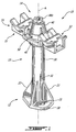
Fig. 1 is an isometric view of a standoff device with cable support in accordance with an embodiment of the present disclosure; -
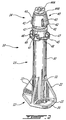
Fig. 2 is an isometric view of the standoff device ofFig. 1 ; -
Fig. 3 is an assembly view of the standoff device ofFig. 1 ; -
Fig. 4 is an isometric view of a component of the standoff device in accordance with an alternative embodiment of the present disclosure; -
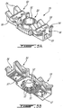
Fig. 5A is an isometric view of the cable support ofFig. 1 , from an upper standpoint; -
Fig. 5B is an isometric view of the cable support ofFig. 1 , from a lower standpoint; -
Fig. 6 is a partly sectioned view of the standoff device and cable support ofFig. 1 , as used to connect wire harnesses to a structure; -
Fig. 7 is an isometric view of the standoff device and cable support ofFig. 1 , with a removal tool; -
Fig. 8 is an assembly view of the standoff device ofFig. 1 with a single cable support, in accordance with another embodiment of the present disclosure; -
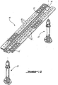
Fig. 9 is an isometric view of the standoff device ofFig. 1 with a hat support; and -
Fig. 10 is a flow chart illustrating a connection and disconnection of a wire harness to a structure with a standoff device, such as the standoff device ofFig. 1 . - Referring to the drawings, and more particularly to
Figs. 1-3 , a standoff device is generally shown at 10. The standoff device, occasionally referred to hereinafter as "device 10" for simplicity purposes, is also known as a standoff, harness connector, connection post, among other possible names. Thestandoff device 10 is used to connect a wire harness or wire harnesses to a structure, while physically spacing the wire harness or harnesses apart from the structure (i.e., standing off the wire harness from the structure). - The
device 10 has afixation portion 12, a spacingportion 13, and aconnector portion 14. Acable support 15 is releasably secured to theconnector portion 14 of thedevice 10. - The
fixation portion 12 is the interface between thedevice 10 and a structure. - The spacing
portion 13 projects from thefixation portion 12 and distances theconnector portion 14 from the structure, whereby the wire harness is held at a stand-off distance from the structure. - The
connector portion 14 is the interface of thedevice 10 with thecable support 15. - The
cable support 15 is the interface between the wire harness or harnesses and thedevice 10, and is also referred to in the industry as clip or plastic clip. It is pointed out that other wire harness connector components or other cable-support configurations may be used as alternatives to the double cable support, such as a hat support, tie-down strip, or single cable support. However, for simplicity purposes, reference will be made to acable support 15 in the next paragraphs, although other components can be used instead. - Referring to
Figs. 1-3 , thefixation portion 12 is shown as having abase plate 20. Thebase plate 20 has a generally flat undersurface. In the illustrated embodiment ofFigs. 1-3 , a longitudinal axis A of thedevice 10 is generally normal to the plane of the undersurface of thebase plate 20. However, any other arrangement and angles are considered as well. Moreover, the undersurface of thebase plate 20 may also be curved or may adopt any other appropriate geometries. Thefixation portion 12 may also have other configurations as alternatives to a base plate. -
Holes 21 are provided in thebase plate 20, with one of theholes 21 seen inFigs. 1 to 3 . Theholes 21 are used in conjunction with fasteners, as shown hereinafter, to secure thebase plate 20 to the structure. The fasteners may be bolts, rivets, screws, etc. It is also considered to glue, weld, or braze thebase plate 20 to the structure, provided the bond is of sufficient structural integrity. - Referring to
Fig. 4 , an alternative embodiment of thebase plate 20 is shown at 20', and is similar to that ofFigs. 1-3 . However, the undersurface of the base plate 20' is generally parallel to the longitudinal axis A of thedevice 10. Accordingly, the base plate 20' is selected to fix thedevice 10 to a structure surface parallel to the longitudinal axis A of thedevice 10, while thebase plate 20 is selected in the case of a structure surface in a normal relation with the longitudinal axis. - In
Figs. 1-4 ,reinforcement walls 22 project from thebase plate 20/20' toward the spacingportion 13 and merge withpost 30 of the spacingportion 13. Thereinforcement walls 22 may be present to reinforce the junction between thebase plate 20/20' and thepost 30.Clearances 31 may be defined in thepost 30 adjacent to theholes 21. Theclearances 31 provide additional space for a tool, such as a screwdriver, used to fasten/loosen the fastener received in theholes 21. - In an embodiment, the
fixation portion 12 and the spacingportion 13 are integrally formed in one piece, along with some components of theconnector portion 14. The integrally-formed piece may be molded in polymeric materials, cast in metallic materials, etc. The selection of material depends on the characteristics required for thestandoff device 10 Polymeric materials may be provided for their insulative properties and their low coefficients of thermal expansion. However, other materials may be used as a function of the requirements of wire harness connection. - Referring to
Figs. 1-3 , theconnector portion 14 is shown having a retainingclip 40, by which acable support 15 may be releasably secured to thedevice 10. The retainingclip 40 has a generally frustoconical body or skirt, and is concentrically secured to a free end of thedevice 10. The retainingclip 40 is oriented such that the flared geometry is oriented toward the spacingportion 13. The flared end of the retainingclip 40 is constituted ofresilient tabs 41, at the end of which are abutment edges 42. Theresilient tabs 41 are separated byslits 43. The retainingclip 40 has at least a pair of theresilient tabs 41, but the embodiment ofFigs. 1-3 shows four of theresilient tabs 41. Due to the resilient nature of thetabs 41 and the presence ofslits 43, a pressure applied on the outer surface of the retainingclip 40 will have theresilient tabs 41 move toward one another. - Accordingly, if a component is threaded onto it, the retaining
clip 40 will deform so as to allow the component to pass thereover. Once the component is beyond the abutment edges 42, the retainingclip 40 returns to its flared shape (i.e., reforms), thereby opposing the abutment edges 42 against the component, thus preventing the component from moving axially over the retainingclip 40. - Any other appropriate configuration of clip may be used as an alternative to the frusto-conical skirt shape of
Figs. 2-3 . For instance, it is considered to have a pair of resilient fingers projecting upwardly from the post, with wedge-shape abutments at ends thereof. Accordingly, retaining clip is intended to refer to a component allowing the latching of a cable support or like component to thedevice 10. - Still referring to
Figs. 1-3 , the retainingclip 40 is secured to a free end of thepost 30 by way of afastener 44A.Washers 44B may also be used to reinforce the attachment of the retainingclip 40 to thepost 30. In the event that thefastener 44A is used to secure the retainingclip 40 to thepost 30, thepost 30 is hollow and tapped. Other securing configurations are considered as well. As mentioned, a pair of fingers with wedge-shaped abutments may be used, in which case such fingers may be molded directly with theposts 30. - Still referring to
Figs. 1-3 , theconnector portion 13 has aflange 45. Theflange 45 is located between the abutment edges 42 of the retainingclip 40 and the spacingportion 13. In the embodiment illustrated inFigs. 1-3 , theflange 45 is integrally formed with thepost 30. Theflange 45 has anabutment surface 46 facing toward the abutment edges 42 of the retainingclip 40. The annular space between theabutment surface 46 and the abutment edges 42 defines the location in which thecable support 15 will be held captive. Hence, the distance between such abutments is slight greater to the height of thecable support 15. Theabutment surface 46 will prevent the axial displacement of thecable support 15 toward the structure to which thedevice 10 is connected, while theclip 40 prevents thecable support 15 from moving out of engagement with thedevice 10. Accordingly, by the presence of the abutment edges 42 andsurface 46, thecable support 15 is prevented from axially moving along thedevice 10, once the engagement position ofFig. 1 is reached. - Indexation blocks 47 are formed on the
flange 45 and project axially from theabutment surface 46. In the illustrated embodiment, the indexation blocks 47 are equidistantly spaced apart from one another. The indexation blocks 47 will cooperate with corresponding cavities in thecable support 15 to block thecable support 15 in rotation about the longitudinal axis A. However, the orientation of thecable support 15 may be selected when positioning thecable support 15 onto thedevice 10, as will be described in detail hereinafter. In the illustrated embodiment, the indexation blocks 47 each have a stair configuration. - Cut-
outs 48 may also be present in theflange 45. The cut-outs 48 have an arcuate or semicircular shape, and are in register with theholes 21 in thebase plate 20. Accordingly, an installation tool, such as a screwdriver, may be held substantially parallel to the longitudinal axis A of thedevice 10 when fastening thedevice 10 to a structure via theholes 21. - An
absorber 49 may be located in the space between the abutment edges 42 and theabutment surface 46 or at other locations. Theabsorber 49 projects radially outwardly from the surface of thepost 30. Accordingly, theabsorber 49 may slightly deform when thecable support 15 is in the engagement position ofFig. 1 on thedevice 10, thereby absorbing a portion of vibrations between thedevice 10 and thecable support 15. In the illustrated embodiment, theabsorber 49 is an O-ring, but may also be any other type of seal or like component. The material selected for theabsorber 49, for instance an elastomeric material, must be capable of sustaining the conditions to which thedevice 10 will be exposed. - Referring to
Figs. 5A and 5B , thecable support 15 is shown in greater detail, as separated from thedevice 10. Thecable support 15 is adouble cable support 15, as it may be used with a pair of wire harnesses. Thecable support 15 has aconnector portion 50 that will collaborate with theconnector portion 14 of the device 10 (Fig. 1 ) for the releasable interconnection between thedevice 10 and thecable support 15. Accordingly, theconnector 50 features a throughbore 51 having a diameter slightly greater than that of theconnector portion 14 of thedevice 10 between the abutment edges 42 and theabutment surface 46. The throughbore 51 may also slightly taper from top to bottom to facilitate the axial engagement of thecable support 15 onto thedevice 10 via the retainingclip 40. - In the underside of the
connector portion 50,indexation cavities 52 are defined. The indexation cavities 52 are radially spaced apart and may be equidistant from one another. The indexation cavities 52 are sized so as to accommodate the indexation blocks 47 (Figs. 2 and3 ) of theconnector portion 14. Accordingly, when the indexation blocks 47 are received in theindexation cavities 52, thecable support 15 is prevented from rotating about the longitudinal axis A of thedevice 10. Although eight of theindexation cavities 52 are illustrated, more or fewer ofsuch indexation cavities 52 may be provided in theconnector portion 50 of thecable support 15. It is pointed out that there must be some correspondence between the positioning and the spacing apart of the indexation blocks 47 of the connector portion 14 (Figs. 2 and3 ) and theindexation cavities 52 ofFig. 5B for their cooperative engagement. - The combination of indexation cavities and indexation blocks (i.e., the indexation formations) may be reversed, with the indexation cavities being present on the
device 10 while thecable support 15 would have appropriate indexation blocks. Other arrangements of indexation formations are possible as well for the indexing of thecable support 15 relative to thedevice 10. - Cable interfaces 53 project laterally from the
connector portion 50. Thecable support 15 features a pair of the cable interfaces 53 (i.e., "double" cable support 15), but may also have a single one or numerous of such cable interfaces 53. For instance, in an embodiment, thecable support 15 is aquadruple cable support 15, in that it comprises the equivalent of thedouble cable support 15 ofFig. 5A in a set of two positioned back to back. In such a case, thedevice 10 must be sized so as to accommodate such a quadruple cable support. - Each of the cable interfaces 53 have support surfaces 54. The support surfaces 54 are arranged in a trough shape, upon which will be seated a wire harness (or bundle of wires, or single wires, tubes, etc). Other shapes are considered as well. A
lug 55 is transversely positioned with respect to the support surfaces 54, with apassage 56 being defined thereunder. Therefore, a fastener strip, such as a tie wrap, cable or the like, may be passed into thepassage 56, as shown inFig. 6 , whereby thewire harness 60 may be tied to thecable interface 53 and abutted against the support surfaces 54. Anopening 57 may be provided to access the fastening strip, for instance, for cutting it off. Referring toFig. 6 , it is shown that tie wraps 60 is used to connect the wire harnesses 61 of the wire harness to thedevice 10. Thedevice 10 is secured to a structure B by fasteners C. In an embodiment, the structure B is part of an aircraft, whereby the wire harnesses 61 are part of the aircraft. - Referring to
Fig. 8 , asingle cable support 15 is shown at 80. Thesingle cable support 80 is similar in construction to thedouble cable support 15 ofFigs. 5A and 5B , but features only one of the cable interfaces 53. - Referring to
Fig. 9 , other components of wire harnesses may be used, such as tie-down strips orhat support 90. Thehat support 90 has a pair of throughbores 91 at opposed ends, so as to be connected by a pair of thestandoff devices 10 to a structure. A plurality of openings are provided in thesupport 90 so as to receive strips, cables, tie wraps or the like. Moreover, achannel 93 is also defined in thehat support 90, and is typically defined to enhance the interconnection between thehat support 90 and wire harnesses or the like strapped thereon. - Now that the
standoff device 10 and thecable support 15 have been described, the installation of thecable support 15 onto thedevice 10 is now detailed with reference toFig. 10 , asmethods 100. Prior to installation of thecable support 15 on thedevice 10, thedevice 10 is secured to the structure, and the wire harness/wire harnesses 61 may already be strapped onto thecable support 15 in the manner shown inFig. 6 . Alternatively, thecable support 15 may be connected to thedevice 10 prior to the strapping of the wire harnesses 61 thereon. - Referring concurrently to
Figs. 6 to 10 , thecable support 15 is manually aligned with thedevice 10, such that the throughbore 51 is generally concentric with the longitudinal axis A of thedevice 10. Moreover, theindexation cavities 52 are oriented toward the indexation blocks 47 of thedevice 10. As shown in 101, theconnector portion 14 is then threaded through the throughbore 51 of thecable support 15. By moving thecable support 15 along the longitudinal axis A, the retainingclip 40 slightly deforms when thecable support 15 passes over it. - Prior to the
cable support 15 reaching the engagement position ofFig. 1 , and thus prior to the engagement of the indexation blocks 47 into theindexation cavities 52, thecable support 15 may be rotated about the longitudinal axis A in accordance with 102, to adjust an orientation of thecable support 15 relative to thedevice 10. It is pointed out that the pressure applied by theresilient tabs 41 is sufficient to keep thecable support 15 blocked onto the retainingclip 40 while not preventing rotation of thecable support 15. - Once a desired orientation of the
cable support 15 is reached, thecable support 15 is moved further along the longitudinal axis A, at which point thecable support 15 will be beyond the abutment edges 42 of the retainingclip 40 in accordance with 103, and thus in the engagement position ofFig. 1 . When thecable support 15 is beyond the abutment edges 42, the retainingclip 40 regains its initial shape, thereby preventing axial displacement of thecable support 15 out of engagement with the device. In this engagement position, as illustrated inFig. 1 , the indexation blocks 47 are received in theindexation cavities 52. Thecable support 15 will therefore be latched onto the device 10 (i.e., automatically blocked as a result of the translation engagement movement), as thecable support 15 is releasably secured to thedevice 10. - In order to remove the
cable support 15 from thedevice 10, a tool is used as illustrated inFig. 7 . The tool has asocket 70 at an end of a shaft 71. A handle may be provided at the opposed end of the shaft 71 to facilitate manoeuvring by an operator. Thesocket 70 is a cylindrical tube having aninner diameter 72 essentially similar to that of the throughbore 51 of thecable support 15. Thesocket 70 is moved along longitudinal axis A of thedevice 10 until it engages with the retainingclip 40, in accordance with 104. As thesocket 70 is moved along the longitudinal axis A, it will compress the retainingclip 40 in such a way that theresilient tabs 41 adopt concurrently a generally cylindrical shape. In doing so, the diameter of the retainingclip 40 is smaller than that of the throughbore 51. Therefore, by applying an ejection pressure on thecable support 15 along longitudinal axis A in accordance with 105 (i.e., from thefixation portion 12 toward the connector portion 14), thecable support 15 will move out of engagement with thedevice 10, by passing over the retainingclip 40 in accordance with 106. - Modifications and improvements to the above-described embodiments of the present invention may become apparent to those skilled in the art. The foregoing description is intended to be exemplary rather than limiting. The scope of the present invention is therefore intended to be limited solely by the scope of the appended claims.
Claims (15)
- A standoff device (10) for connecting a wire harness (60) to a structure (B), comprising:a fixation portion (12) adapted to be secured to the structure;a spacing portion (13) connected at a first end to the fixation portion (12); anda connector portion (14) connected to a second end of the spacing portion (13) and spaced apart from the fixation portion (12), the connector portion (14) comprising a retaining clip (40) adapted to resiliently deform when a wire harness connector component moves axially thereon toward the fixation portion (12) and adapted to oppose at least one abutment edge (42) against a first portion of the connector component into an engagement position when the connector component is past the retaining clip (40) to prevent the connector component from moving back onto the retaining clip (40), and at least one abutment surface (46) adapted to contact a second portion of the connector component in the engagement position to prevent further axial movement of the connector component toward the fixation portion (12), whereby the connector component is held captive between the at least one edge and the at least one abutment surface (46)
characterized in that the retaining clip (40) is arranged to be deformed by a socket (70) so that a cable support (15) engaged with the retaining clip (40) can be disengaged. - The standoff device according to claim 1, further comprising an elastomeric absorber (49) on the connector portion (14) between the at least one abutment edge (42) and the at least one abutment surface (46), the elastomeric absorber (49) adapted to contact the wire harness connector component in the engagement position.
- The standoff device according to any one of claims 1 and 2, further comprising indexation formations (47) between the at least one abutment edge (42) and the at least one abutment surface (46), the indexation formations (47) adapted to be indexingly engaged with complementary indexation formations (52) on the wire harness connector component, whereby the wire harness connector component is blocked in orientation relative to the standoff device.
- The standoff device according to claim 3, wherein the indexation formations (47) are indexation blocks each having a stair geometry.
- The standoff device according to any one of claims 1 to 4, wherein the at least one abutment surface (46) is part of a flange (45) on the connector portion (14).
- The standoff device according to claim 5, further comprising at least one cut-out (48) in the flange (45), the at least one cut-out (48) being in alignment with a respective fastener (44A) of the fixation portion (12).
- The standoff device according to any one of claims 1 to 6, wherein the fixation portion (12) has a base plate (20) having an undersurface adapted to be laid onto the structure when the standoff device (10) is secured to the structure (B).
- The standoff device according to any one of claims 1 to 7, wherein the retaining clip (40) has a skirt geometry, with a flared portion of the retaining clip oriented toward the fixation portion (12).
- The standoff device according to claim 8, wherein the flared portion comprises at least two resilient tabs (41), with each of the resilient tabs (41) comprising one of the abutment edges (42).
- A cable support (15) for connecting a wire harness (60) to a standoff device (10) according to any one of the claims 1 to 9, comprising:at least one cable interface adapted to support a wire harness portion attached thereto; anda connector portion connected to the at least one cable interface, the connector portion (14) comprising a through bore (51) adapted to be threaded onto a standoff device (10) to resiliently deform a retaining clip (40) to be held captive to the standoff device (10) when passed the retaining clip (40), and indexation formations (47) adapted to be indexingly engaged with complementary indexation formations (52) on the standoff device (10), whereby the cable support (15) is blocked in orientation relative to the standoff device (10).
- The cable support (15) according to claim 10, wherein the indexation formations (47) are indexation cavities defined in the connector portion, the indexation cavities each having a stair geometry.
- The cable support according to any one of claims 10 to 11, wherein the through bore (51) has a tapering geometry.
- A method for connecting and disconnecting a wire harness (60) to a structure (B) with a standoff device (10), comprising:threading an opening of a wire harness connector component onto a retaining clip (40) of a standoff device (10) to resiliently deform the retaining clip (40);moving the connector component beyond the retaining clip (40) on the standoff device (10) and into captive engagement with the standoff device (10) by the retaining clip (40) reforming;characterized in that the method further comprises placing a socket (70) on the retaining clip (40) to resiliently deform the retaining clip (40);pushing the connector component onto the deformed retaining clip (40); andremoving the connector component from engagement with the standoff device (10).
- The method according to claim 13, further comprising rotating the connector component about a longitudinal axis of the standoff device (10) while on the retaining clip (40) until a desired orientation of the connector component is reached relative to the standoff device (10).
- An aircraft comprising:a structural element (B);at least one wire harness (60) with at least one wire harness connector component; anda standoff device (10) for connecting the wire harness (60) to the structural element (B) according to any one of claims 1 to 9.
Applications Claiming Priority (1)
| Application Number | Priority Date | Filing Date | Title |
|---|---|---|---|
| PCT/IB2011/000512 WO2012120321A1 (en) | 2011-03-10 | 2011-03-10 | Standoff device and method of installation of harness |
Publications (2)
| Publication Number | Publication Date |
|---|---|
| EP2684266A1 EP2684266A1 (en) | 2014-01-15 |
| EP2684266B1 true EP2684266B1 (en) | 2016-09-28 |
Family
ID=44626237
Family Applications (1)
| Application Number | Title | Priority Date | Filing Date |
|---|---|---|---|
| EP11718486.1A Active EP2684266B1 (en) | 2011-03-10 | 2011-03-10 | Standoff device and method of installation of harness |
Country Status (5)
| Country | Link |
|---|---|
| US (1) | US9508472B2 (en) |
| EP (1) | EP2684266B1 (en) |
| CN (1) | CN103503260B (en) |
| CA (2) | CA2829748C (en) |
| WO (1) | WO2012120321A1 (en) |
Families Citing this family (22)
| Publication number | Priority date | Publication date | Assignee | Title |
|---|---|---|---|---|
| NZ622790A (en) * | 2009-06-30 | 2015-03-27 | Schiavello Vic Pty Ltd | Reconfigurable workstation support |
| FI8766U1 (en) * | 2009-10-23 | 2010-06-21 | Pistora Oy | Cable Fasteners |
| EP2787586B1 (en) * | 2013-04-05 | 2016-08-10 | Airbus Operations GmbH | Installation assembly for bridging a cable harness or the like between two aircraft structure elements |
| ES2707730T3 (en) * | 2013-09-13 | 2019-04-04 | Te Connectivity Corp | Adjustable cable managers |
| DE102013227051B4 (en) * | 2013-12-20 | 2017-03-30 | Leoni Kabel Holding Gmbh | Measuring arrangement and method for temperature measurement and sensor cable for such a measuring arrangement |
| WO2015151269A1 (en) * | 2014-04-04 | 2015-10-08 | 三菱電機株式会社 | Insulative support for electric device |
| CN106099795A (en) * | 2016-06-23 | 2016-11-09 | 重庆星特龙实业有限公司 | Entrance line support |
| FR3055033B1 (en) * | 2016-08-12 | 2019-05-17 | Safran Electrical & Power | DEVICE FOR FIXING AT LEAST ONE CABLE IN AN AIRCRAFT OR AIRCRAFT ENGINE OR FOR SPATIAL APPLICATION |
| FR3055391B1 (en) * | 2016-09-01 | 2019-06-14 | Peugeot Citroen Automobiles Sa | DEVICE FOR HOLDING PIPES ASSOCIATED WITH A TANK FOR A MOTOR VEHICLE |
| EP3336989B1 (en) * | 2016-12-16 | 2020-07-22 | HellermannTyton GmbH | Cable fixation device |
| US10473240B2 (en) * | 2017-03-01 | 2019-11-12 | C&D Zodiac, Inc. | Hose mounting assembly |
| US10896774B2 (en) * | 2017-03-21 | 2021-01-19 | Hubbell Incorporated | Non-conductive support stands |
| CN106877251A (en) * | 2017-03-30 | 2017-06-20 | 中国航空工业集团公司西安飞机设计研究所 | A vertical and horizontal dual-purpose high support seat |
| US10598302B2 (en) * | 2017-12-27 | 2020-03-24 | TorcSill Foundations, LLC | Safety anchor device for high pressure pipe couplings |
| EP3737588B1 (en) | 2018-01-02 | 2022-01-12 | Volvo Truck Corporation | A holder arrangement comprising a bracket and a spacer, and a manufacturing method for manufacturing a spacer |
| FR3084434B1 (en) * | 2018-07-25 | 2020-11-27 | Avon Polymeres France | ADJUSTABLE FIXING SUPPORT FOR MOUNTING A TUBULAR ARTICLE ON AN EXTERNAL BODY |
| CN110817598B (en) * | 2019-11-23 | 2021-07-20 | 国网河南省电力公司南阳供电公司 | A wire storage device |
| EP4323653A4 (en) * | 2021-04-15 | 2025-01-29 | Outdoor Wireless Networks LLC | Adapter for mounting cable hangers |
| FR3130088B1 (en) * | 2021-12-02 | 2023-12-29 | Amphenol Air Lb | Device for fixing an object to a structure |
| US20230375108A1 (en) * | 2022-05-23 | 2023-11-23 | Ubicquia, Inc. | Stud-mountable cable retention apparatus and system |
| EP4583336A1 (en) * | 2024-01-05 | 2025-07-09 | B/E Aerospace, Inc. | Adjustable spacing device |
| KR102941819B1 (en) * | 2024-07-18 | 2026-03-19 | 이정영 | Piping stand for work |
Family Cites Families (22)
| Publication number | Priority date | Publication date | Assignee | Title |
|---|---|---|---|---|
| US4563131A (en) * | 1984-04-30 | 1986-01-07 | Mechanical Technology Incorporated | Variable displacement blower |
| FR2662866B1 (en) * | 1990-06-01 | 1992-11-27 | Dassault Avions | MODULAR ASSEMBLY FOR SUPPORTING ELECTRIC CABLES. |
| US5271588A (en) * | 1992-07-17 | 1993-12-21 | General Electric Company | Multi-piece tube clamp |
| JP2587328Y2 (en) * | 1992-11-13 | 1998-12-16 | ポップリベット・ファスナー株式会社 | Pipe holder |
| DE4305963C2 (en) * | 1993-02-26 | 1995-04-27 | Deutsche Aerospace Airbus | Spacers for cables, in particular for electrical cable bundles in aircraft |
| US6196751B1 (en) * | 1998-09-11 | 2001-03-06 | Thomas & Betts International, Inc. | Stud mounted fastener for routing wire |
| JP3976619B2 (en) | 2002-05-29 | 2007-09-19 | 矢崎総業株式会社 | Long member fixture |
| US7654492B2 (en) | 2004-05-03 | 2010-02-02 | The Boeing Company | Wire bundle support system |
| US6903275B1 (en) | 2004-10-22 | 2005-06-07 | Yazaki North America, Inc. | Mounting device for a wire harness shield |
| DE102005026471B4 (en) * | 2005-06-09 | 2008-05-08 | Itw Automotive Products Gmbh & Co. Kg | Holder for a wire in an automobile |
| US7484698B2 (en) | 2006-04-21 | 2009-02-03 | Michael Budagher | Stackable transmission line hanger |
| US7497718B2 (en) | 2006-11-08 | 2009-03-03 | International Truck Intellectual Property Company, Llc | Routing clip elements with a living hinge and interlocking closure |
| US7740209B2 (en) | 2007-07-27 | 2010-06-22 | Hewlett-Packard Development Company, L.P. | Cable routing device |
| US7549613B1 (en) | 2007-09-24 | 2009-06-23 | Sioux Chief Mfg. Co., Inc. | Tube clamp for an angle bracket |
| JP5066731B2 (en) | 2008-03-18 | 2012-11-07 | ポップリベット・ファスナー株式会社 | Multiple wire harness clamps |
| US8011621B2 (en) | 2008-05-29 | 2011-09-06 | Andrew Llc | Snap-in cable hanger clip |
| DE102008041230B4 (en) * | 2008-08-13 | 2019-01-17 | Airbus Operations Gmbh | Holder for fixing at least one line |
| US8042774B2 (en) | 2008-10-03 | 2011-10-25 | Panduit Corp. | Control panel mount having one or more strain relief features |
| DE102009017977A1 (en) * | 2009-04-21 | 2010-10-28 | Airbus Deutschland Gmbh | Holding device for mounted within a fuselage attachments |
| GB201009965D0 (en) * | 2010-06-15 | 2010-07-21 | Airbus Operations Ltd | Aircraft conduit harness retention system |
| WO2013114147A1 (en) * | 2012-02-02 | 2013-08-08 | Bombardier Inc. | Cable retainer device and method for retaining cable in an aircraft |
| DE202012007989U1 (en) * | 2012-08-20 | 2013-12-04 | S-Fasteners Gmbh | Cable holder assembly |
-
2011
- 2011-03-10 CA CA2829748A patent/CA2829748C/en active Active
- 2011-03-10 EP EP11718486.1A patent/EP2684266B1/en active Active
- 2011-03-10 CN CN201180070541.6A patent/CN103503260B/en active Active
- 2011-03-10 CA CA3049824A patent/CA3049824A1/en not_active Abandoned
- 2011-03-10 WO PCT/IB2011/000512 patent/WO2012120321A1/en not_active Ceased
- 2011-03-10 US US14/003,428 patent/US9508472B2/en active Active
Also Published As
| Publication number | Publication date |
|---|---|
| US20140060891A1 (en) | 2014-03-06 |
| CN103503260B (en) | 2017-08-29 |
| EP2684266A1 (en) | 2014-01-15 |
| CA2829748C (en) | 2019-09-10 |
| CN103503260A (en) | 2014-01-08 |
| US9508472B2 (en) | 2016-11-29 |
| WO2012120321A1 (en) | 2012-09-13 |
| CA3049824A1 (en) | 2012-09-13 |
| CA2829748A1 (en) | 2012-09-13 |
Similar Documents
| Publication | Publication Date | Title |
|---|---|---|
| US9508472B2 (en) | Standoff device and method of installation of harness | |
| US8757560B2 (en) | Cable retention device | |
| US7654492B2 (en) | Wire bundle support system | |
| US5423647A (en) | Stud bolt clip | |
| EP2815477B1 (en) | Cable retainer device and method for retaining cable in an aircraft | |
| US9254908B2 (en) | Fixing means | |
| US20160268965A1 (en) | Mounting bracket assmebly | |
| US20110039430A1 (en) | Fastening assembly and method | |
| US20130071179A1 (en) | Fastening Device for Attachment to a Mounting Rail | |
| WO2014160942A1 (en) | Mounting clips for panel installation | |
| US20050121560A1 (en) | Quick release support post and associated method | |
| US20120137494A1 (en) | Device for fastening an element of elongate shape to a turbine engine casing | |
| CN101443973A (en) | Isolation and/or reinforcement for cableways | |
| US10644491B2 (en) | Electrical box cable connector | |
| WO2014066317A1 (en) | Mounting feature for a cable tie | |
| EP1441428B1 (en) | Button fastening device | |
| EP4080701A1 (en) | Cable tray clips and methods for using the same | |
| EP0844715A1 (en) | Cable fastening device | |
| JP7661712B2 (en) | Harness fixing structure | |
| CA2717548A1 (en) | Fastening assembly and method |
Legal Events
| Date | Code | Title | Description |
|---|---|---|---|
| PUAI | Public reference made under article 153(3) epc to a published international application that has entered the european phase |
Free format text: ORIGINAL CODE: 0009012 |
|
| 17P | Request for examination filed |
Effective date: 20130905 |
|
| AK | Designated contracting states |
Kind code of ref document: A1 Designated state(s): AL AT BE BG CH CY CZ DE DK EE ES FI FR GB GR HR HU IE IS IT LI LT LU LV MC MK MT NL NO PL PT RO RS SE SI SK SM TR |
|
| DAX | Request for extension of the european patent (deleted) | ||
| REG | Reference to a national code |
Ref country code: DE Ref legal event code: R079 Ref document number: 602011030740 Country of ref document: DE Free format text: PREVIOUS MAIN CLASS: H02G0003300000 Ipc: H01B0017160000 |
|
| GRAP | Despatch of communication of intention to grant a patent |
Free format text: ORIGINAL CODE: EPIDOSNIGR1 |
|
| RIC1 | Information provided on ipc code assigned before grant |
Ipc: H02G 3/30 20060101ALI20160307BHEP Ipc: H01B 17/16 20060101AFI20160307BHEP |
|
| INTG | Intention to grant announced |
Effective date: 20160407 |
|
| GRAS | Grant fee paid |
Free format text: ORIGINAL CODE: EPIDOSNIGR3 |
|
| GRAA | (expected) grant |
Free format text: ORIGINAL CODE: 0009210 |
|
| AK | Designated contracting states |
Kind code of ref document: B1 Designated state(s): AL AT BE BG CH CY CZ DE DK EE ES FI FR GB GR HR HU IE IS IT LI LT LU LV MC MK MT NL NO PL PT RO RS SE SI SK SM TR |
|
| REG | Reference to a national code |
Ref country code: GB Ref legal event code: FG4D |
|
| REG | Reference to a national code |
Ref country code: CH Ref legal event code: EP |
|
| REG | Reference to a national code |
Ref country code: AT Ref legal event code: REF Ref document number: 833363 Country of ref document: AT Kind code of ref document: T Effective date: 20161015 |
|
| REG | Reference to a national code |
Ref country code: IE Ref legal event code: FG4D |
|
| REG | Reference to a national code |
Ref country code: DE Ref legal event code: R096 Ref document number: 602011030740 Country of ref document: DE |
|
| REG | Reference to a national code |
Ref country code: LT Ref legal event code: MG4D |
|
| PG25 | Lapsed in a contracting state [announced via postgrant information from national office to epo] |
Ref country code: NO Free format text: LAPSE BECAUSE OF FAILURE TO SUBMIT A TRANSLATION OF THE DESCRIPTION OR TO PAY THE FEE WITHIN THE PRESCRIBED TIME-LIMIT Effective date: 20161228 Ref country code: LT Free format text: LAPSE BECAUSE OF FAILURE TO SUBMIT A TRANSLATION OF THE DESCRIPTION OR TO PAY THE FEE WITHIN THE PRESCRIBED TIME-LIMIT Effective date: 20160928 Ref country code: HR Free format text: LAPSE BECAUSE OF FAILURE TO SUBMIT A TRANSLATION OF THE DESCRIPTION OR TO PAY THE FEE WITHIN THE PRESCRIBED TIME-LIMIT Effective date: 20160928 Ref country code: RS Free format text: LAPSE BECAUSE OF FAILURE TO SUBMIT A TRANSLATION OF THE DESCRIPTION OR TO PAY THE FEE WITHIN THE PRESCRIBED TIME-LIMIT Effective date: 20160928 Ref country code: FI Free format text: LAPSE BECAUSE OF FAILURE TO SUBMIT A TRANSLATION OF THE DESCRIPTION OR TO PAY THE FEE WITHIN THE PRESCRIBED TIME-LIMIT Effective date: 20160928 |
|
| REG | Reference to a national code |
Ref country code: NL Ref legal event code: MP Effective date: 20160928 |
|
| REG | Reference to a national code |
Ref country code: AT Ref legal event code: MK05 Ref document number: 833363 Country of ref document: AT Kind code of ref document: T Effective date: 20160928 |
|
| PG25 | Lapsed in a contracting state [announced via postgrant information from national office to epo] |
Ref country code: LV Free format text: LAPSE BECAUSE OF FAILURE TO SUBMIT A TRANSLATION OF THE DESCRIPTION OR TO PAY THE FEE WITHIN THE PRESCRIBED TIME-LIMIT Effective date: 20160928 Ref country code: SE Free format text: LAPSE BECAUSE OF FAILURE TO SUBMIT A TRANSLATION OF THE DESCRIPTION OR TO PAY THE FEE WITHIN THE PRESCRIBED TIME-LIMIT Effective date: 20160928 Ref country code: GR Free format text: LAPSE BECAUSE OF FAILURE TO SUBMIT A TRANSLATION OF THE DESCRIPTION OR TO PAY THE FEE WITHIN THE PRESCRIBED TIME-LIMIT Effective date: 20161229 Ref country code: NL Free format text: LAPSE BECAUSE OF FAILURE TO SUBMIT A TRANSLATION OF THE DESCRIPTION OR TO PAY THE FEE WITHIN THE PRESCRIBED TIME-LIMIT Effective date: 20160928 |
|
| REG | Reference to a national code |
Ref country code: FR Ref legal event code: PLFP Year of fee payment: 7 |
|
| PG25 | Lapsed in a contracting state [announced via postgrant information from national office to epo] |
Ref country code: RO Free format text: LAPSE BECAUSE OF FAILURE TO SUBMIT A TRANSLATION OF THE DESCRIPTION OR TO PAY THE FEE WITHIN THE PRESCRIBED TIME-LIMIT Effective date: 20160928 Ref country code: EE Free format text: LAPSE BECAUSE OF FAILURE TO SUBMIT A TRANSLATION OF THE DESCRIPTION OR TO PAY THE FEE WITHIN THE PRESCRIBED TIME-LIMIT Effective date: 20160928 |
|
| PG25 | Lapsed in a contracting state [announced via postgrant information from national office to epo] |
Ref country code: SM Free format text: LAPSE BECAUSE OF FAILURE TO SUBMIT A TRANSLATION OF THE DESCRIPTION OR TO PAY THE FEE WITHIN THE PRESCRIBED TIME-LIMIT Effective date: 20160928 Ref country code: CZ Free format text: LAPSE BECAUSE OF FAILURE TO SUBMIT A TRANSLATION OF THE DESCRIPTION OR TO PAY THE FEE WITHIN THE PRESCRIBED TIME-LIMIT Effective date: 20160928 Ref country code: PL Free format text: LAPSE BECAUSE OF FAILURE TO SUBMIT A TRANSLATION OF THE DESCRIPTION OR TO PAY THE FEE WITHIN THE PRESCRIBED TIME-LIMIT Effective date: 20160928 Ref country code: PT Free format text: LAPSE BECAUSE OF FAILURE TO SUBMIT A TRANSLATION OF THE DESCRIPTION OR TO PAY THE FEE WITHIN THE PRESCRIBED TIME-LIMIT Effective date: 20170130 Ref country code: BG Free format text: LAPSE BECAUSE OF FAILURE TO SUBMIT A TRANSLATION OF THE DESCRIPTION OR TO PAY THE FEE WITHIN THE PRESCRIBED TIME-LIMIT Effective date: 20161228 Ref country code: SK Free format text: LAPSE BECAUSE OF FAILURE TO SUBMIT A TRANSLATION OF THE DESCRIPTION OR TO PAY THE FEE WITHIN THE PRESCRIBED TIME-LIMIT Effective date: 20160928 Ref country code: IS Free format text: LAPSE BECAUSE OF FAILURE TO SUBMIT A TRANSLATION OF THE DESCRIPTION OR TO PAY THE FEE WITHIN THE PRESCRIBED TIME-LIMIT Effective date: 20170128 Ref country code: ES Free format text: LAPSE BECAUSE OF FAILURE TO SUBMIT A TRANSLATION OF THE DESCRIPTION OR TO PAY THE FEE WITHIN THE PRESCRIBED TIME-LIMIT Effective date: 20160928 Ref country code: AT Free format text: LAPSE BECAUSE OF FAILURE TO SUBMIT A TRANSLATION OF THE DESCRIPTION OR TO PAY THE FEE WITHIN THE PRESCRIBED TIME-LIMIT Effective date: 20160928 Ref country code: BE Free format text: LAPSE BECAUSE OF FAILURE TO SUBMIT A TRANSLATION OF THE DESCRIPTION OR TO PAY THE FEE WITHIN THE PRESCRIBED TIME-LIMIT Effective date: 20160928 |
|
| REG | Reference to a national code |
Ref country code: DE Ref legal event code: R097 Ref document number: 602011030740 Country of ref document: DE |
|
| PG25 | Lapsed in a contracting state [announced via postgrant information from national office to epo] |
Ref country code: IT Free format text: LAPSE BECAUSE OF FAILURE TO SUBMIT A TRANSLATION OF THE DESCRIPTION OR TO PAY THE FEE WITHIN THE PRESCRIBED TIME-LIMIT Effective date: 20160928 |
|
| PG25 | Lapsed in a contracting state [announced via postgrant information from national office to epo] |
Ref country code: DK Free format text: LAPSE BECAUSE OF FAILURE TO SUBMIT A TRANSLATION OF THE DESCRIPTION OR TO PAY THE FEE WITHIN THE PRESCRIBED TIME-LIMIT Effective date: 20160928 |
|
| PLBE | No opposition filed within time limit |
Free format text: ORIGINAL CODE: 0009261 |
|
| STAA | Information on the status of an ep patent application or granted ep patent |
Free format text: STATUS: NO OPPOSITION FILED WITHIN TIME LIMIT |
|
| 26N | No opposition filed |
Effective date: 20170629 |
|
| REG | Reference to a national code |
Ref country code: CH Ref legal event code: PL |
|
| PG25 | Lapsed in a contracting state [announced via postgrant information from national office to epo] |
Ref country code: SI Free format text: LAPSE BECAUSE OF FAILURE TO SUBMIT A TRANSLATION OF THE DESCRIPTION OR TO PAY THE FEE WITHIN THE PRESCRIBED TIME-LIMIT Effective date: 20160928 Ref country code: MC Free format text: LAPSE BECAUSE OF FAILURE TO SUBMIT A TRANSLATION OF THE DESCRIPTION OR TO PAY THE FEE WITHIN THE PRESCRIBED TIME-LIMIT Effective date: 20160928 |
|
| REG | Reference to a national code |
Ref country code: IE Ref legal event code: MM4A |
|
| PG25 | Lapsed in a contracting state [announced via postgrant information from national office to epo] |
Ref country code: LU Free format text: LAPSE BECAUSE OF NON-PAYMENT OF DUE FEES Effective date: 20170310 |
|
| PG25 | Lapsed in a contracting state [announced via postgrant information from national office to epo] |
Ref country code: CH Free format text: LAPSE BECAUSE OF NON-PAYMENT OF DUE FEES Effective date: 20170331 Ref country code: IE Free format text: LAPSE BECAUSE OF NON-PAYMENT OF DUE FEES Effective date: 20170310 Ref country code: LI Free format text: LAPSE BECAUSE OF NON-PAYMENT OF DUE FEES Effective date: 20170331 |
|
| REG | Reference to a national code |
Ref country code: FR Ref legal event code: PLFP Year of fee payment: 8 |
|
| PG25 | Lapsed in a contracting state [announced via postgrant information from national office to epo] |
Ref country code: MT Free format text: LAPSE BECAUSE OF NON-PAYMENT OF DUE FEES Effective date: 20170310 |
|
| PG25 | Lapsed in a contracting state [announced via postgrant information from national office to epo] |
Ref country code: AL Free format text: LAPSE BECAUSE OF FAILURE TO SUBMIT A TRANSLATION OF THE DESCRIPTION OR TO PAY THE FEE WITHIN THE PRESCRIBED TIME-LIMIT Effective date: 20160928 |
|
| PG25 | Lapsed in a contracting state [announced via postgrant information from national office to epo] |
Ref country code: HU Free format text: LAPSE BECAUSE OF FAILURE TO SUBMIT A TRANSLATION OF THE DESCRIPTION OR TO PAY THE FEE WITHIN THE PRESCRIBED TIME-LIMIT; INVALID AB INITIO Effective date: 20110310 |
|
| PG25 | Lapsed in a contracting state [announced via postgrant information from national office to epo] |
Ref country code: CY Free format text: LAPSE BECAUSE OF NON-PAYMENT OF DUE FEES Effective date: 20160928 |
|
| PG25 | Lapsed in a contracting state [announced via postgrant information from national office to epo] |
Ref country code: MK Free format text: LAPSE BECAUSE OF FAILURE TO SUBMIT A TRANSLATION OF THE DESCRIPTION OR TO PAY THE FEE WITHIN THE PRESCRIBED TIME-LIMIT Effective date: 20160928 |
|
| PG25 | Lapsed in a contracting state [announced via postgrant information from national office to epo] |
Ref country code: TR Free format text: LAPSE BECAUSE OF FAILURE TO SUBMIT A TRANSLATION OF THE DESCRIPTION OR TO PAY THE FEE WITHIN THE PRESCRIBED TIME-LIMIT Effective date: 20160928 |
|
| PGFP | Annual fee paid to national office [announced via postgrant information from national office to epo] |
Ref country code: GB Payment date: 20260324 Year of fee payment: 16 |
|
| PGFP | Annual fee paid to national office [announced via postgrant information from national office to epo] |
Ref country code: DE Payment date: 20260319 Year of fee payment: 16 |
|
| PGFP | Annual fee paid to national office [announced via postgrant information from national office to epo] |
Ref country code: FR Payment date: 20260320 Year of fee payment: 16 |