EP2683160A2 - Light source apparatus and image projection apparatus - Google Patents
Light source apparatus and image projection apparatus Download PDFInfo
- Publication number
- EP2683160A2 EP2683160A2 EP20130171539 EP13171539A EP2683160A2 EP 2683160 A2 EP2683160 A2 EP 2683160A2 EP 20130171539 EP20130171539 EP 20130171539 EP 13171539 A EP13171539 A EP 13171539A EP 2683160 A2 EP2683160 A2 EP 2683160A2
- Authority
- EP
- European Patent Office
- Prior art keywords
- light
- image
- color
- light source
- emitting device
- Prior art date
- Legal status (The legal status is an assumption and is not a legal conclusion. Google has not performed a legal analysis and makes no representation as to the accuracy of the status listed.)
- Granted
Links
- 239000004065 semiconductor Substances 0.000 claims description 18
- 230000003287 optical effect Effects 0.000 claims description 3
- QSHDDOUJBYECFT-UHFFFAOYSA-N mercury Chemical compound [Hg] QSHDDOUJBYECFT-UHFFFAOYSA-N 0.000 description 25
- 239000003086 colorant Substances 0.000 description 23
- 238000000295 emission spectrum Methods 0.000 description 18
- 238000010586 diagram Methods 0.000 description 10
- 239000011159 matrix material Substances 0.000 description 8
- 229910052724 xenon Inorganic materials 0.000 description 5
- FHNFHKCVQCLJFQ-UHFFFAOYSA-N xenon atom Chemical compound [Xe] FHNFHKCVQCLJFQ-UHFFFAOYSA-N 0.000 description 5
- 238000009877 rendering Methods 0.000 description 4
- 230000002194 synthesizing effect Effects 0.000 description 4
- 239000004973 liquid crystal related substance Substances 0.000 description 2
- 230000003595 spectral effect Effects 0.000 description 2
- 244000025254 Cannabis sativa Species 0.000 description 1
- 238000010276 construction Methods 0.000 description 1
- 238000000034 method Methods 0.000 description 1
- 238000012986 modification Methods 0.000 description 1
- 230000004048 modification Effects 0.000 description 1
Images



Classifications
-
- H—ELECTRICITY
- H04—ELECTRIC COMMUNICATION TECHNIQUE
- H04N—PICTORIAL COMMUNICATION, e.g. TELEVISION
- H04N5/00—Details of television systems
- H04N5/74—Projection arrangements for image reproduction, e.g. using eidophor
- H04N5/7416—Projection arrangements for image reproduction, e.g. using eidophor involving the use of a spatial light modulator, e.g. a light valve, controlled by a video signal
-
- G—PHYSICS
- G03—PHOTOGRAPHY; CINEMATOGRAPHY; ANALOGOUS TECHNIQUES USING WAVES OTHER THAN OPTICAL WAVES; ELECTROGRAPHY; HOLOGRAPHY
- G03B—APPARATUS OR ARRANGEMENTS FOR TAKING PHOTOGRAPHS OR FOR PROJECTING OR VIEWING THEM; APPARATUS OR ARRANGEMENTS EMPLOYING ANALOGOUS TECHNIQUES USING WAVES OTHER THAN OPTICAL WAVES; ACCESSORIES THEREFOR
- G03B21/00—Projectors or projection-type viewers; Accessories therefor
- G03B21/14—Details
- G03B21/20—Lamp housings
- G03B21/2006—Lamp housings characterised by the light source
- G03B21/2013—Plural light sources
-
- G—PHYSICS
- G03—PHOTOGRAPHY; CINEMATOGRAPHY; ANALOGOUS TECHNIQUES USING WAVES OTHER THAN OPTICAL WAVES; ELECTROGRAPHY; HOLOGRAPHY
- G03B—APPARATUS OR ARRANGEMENTS FOR TAKING PHOTOGRAPHS OR FOR PROJECTING OR VIEWING THEM; APPARATUS OR ARRANGEMENTS EMPLOYING ANALOGOUS TECHNIQUES USING WAVES OTHER THAN OPTICAL WAVES; ACCESSORIES THEREFOR
- G03B21/00—Projectors or projection-type viewers; Accessories therefor
- G03B21/14—Details
- G03B21/20—Lamp housings
- G03B21/2006—Lamp housings characterised by the light source
- G03B21/2033—LED or laser light sources
-
- G—PHYSICS
- G03—PHOTOGRAPHY; CINEMATOGRAPHY; ANALOGOUS TECHNIQUES USING WAVES OTHER THAN OPTICAL WAVES; ELECTROGRAPHY; HOLOGRAPHY
- G03B—APPARATUS OR ARRANGEMENTS FOR TAKING PHOTOGRAPHS OR FOR PROJECTING OR VIEWING THEM; APPARATUS OR ARRANGEMENTS EMPLOYING ANALOGOUS TECHNIQUES USING WAVES OTHER THAN OPTICAL WAVES; ACCESSORIES THEREFOR
- G03B33/00—Colour photography, other than mere exposure or projection of a colour film
- G03B33/06—Colour photography, other than mere exposure or projection of a colour film by additive-colour projection apparatus
-
- G—PHYSICS
- G03—PHOTOGRAPHY; CINEMATOGRAPHY; ANALOGOUS TECHNIQUES USING WAVES OTHER THAN OPTICAL WAVES; ELECTROGRAPHY; HOLOGRAPHY
- G03B—APPARATUS OR ARRANGEMENTS FOR TAKING PHOTOGRAPHS OR FOR PROJECTING OR VIEWING THEM; APPARATUS OR ARRANGEMENTS EMPLOYING ANALOGOUS TECHNIQUES USING WAVES OTHER THAN OPTICAL WAVES; ACCESSORIES THEREFOR
- G03B33/00—Colour photography, other than mere exposure or projection of a colour film
- G03B33/10—Simultaneous recording or projection
- G03B33/12—Simultaneous recording or projection using beam-splitting or beam-combining systems, e.g. dichroic mirrors
-
- H—ELECTRICITY
- H04—ELECTRIC COMMUNICATION TECHNIQUE
- H04N—PICTORIAL COMMUNICATION, e.g. TELEVISION
- H04N5/00—Details of television systems
- H04N5/74—Projection arrangements for image reproduction, e.g. using eidophor
-
- H—ELECTRICITY
- H04—ELECTRIC COMMUNICATION TECHNIQUE
- H04N—PICTORIAL COMMUNICATION, e.g. TELEVISION
- H04N9/00—Details of colour television systems
- H04N9/12—Picture reproducers
- H04N9/31—Projection devices for colour picture display, e.g. using electronic spatial light modulators [ESLM]
-
- H—ELECTRICITY
- H04—ELECTRIC COMMUNICATION TECHNIQUE
- H04N—PICTORIAL COMMUNICATION, e.g. TELEVISION
- H04N9/00—Details of colour television systems
- H04N9/12—Picture reproducers
- H04N9/31—Projection devices for colour picture display, e.g. using electronic spatial light modulators [ESLM]
- H04N9/3102—Projection devices for colour picture display, e.g. using electronic spatial light modulators [ESLM] using two-dimensional electronic spatial light modulators
- H04N9/3111—Projection devices for colour picture display, e.g. using electronic spatial light modulators [ESLM] using two-dimensional electronic spatial light modulators for displaying the colours sequentially, e.g. by using sequentially activated light sources
-
- H—ELECTRICITY
- H04—ELECTRIC COMMUNICATION TECHNIQUE
- H04N—PICTORIAL COMMUNICATION, e.g. TELEVISION
- H04N9/00—Details of colour television systems
- H04N9/12—Picture reproducers
- H04N9/31—Projection devices for colour picture display, e.g. using electronic spatial light modulators [ESLM]
- H04N9/3141—Constructional details thereof
- H04N9/315—Modulator illumination systems
- H04N9/3158—Modulator illumination systems for controlling the spectrum
-
- H—ELECTRICITY
- H04—ELECTRIC COMMUNICATION TECHNIQUE
- H04N—PICTORIAL COMMUNICATION, e.g. TELEVISION
- H04N9/00—Details of colour television systems
- H04N9/12—Picture reproducers
- H04N9/31—Projection devices for colour picture display, e.g. using electronic spatial light modulators [ESLM]
- H04N9/3141—Constructional details thereof
- H04N9/315—Modulator illumination systems
- H04N9/3164—Modulator illumination systems using multiple light sources
-
- H—ELECTRICITY
- H04—ELECTRIC COMMUNICATION TECHNIQUE
- H04N—PICTORIAL COMMUNICATION, e.g. TELEVISION
- H04N9/00—Details of colour television systems
- H04N9/12—Picture reproducers
- H04N9/31—Projection devices for colour picture display, e.g. using electronic spatial light modulators [ESLM]
- H04N9/3179—Video signal processing therefor
- H04N9/3182—Colour adjustment, e.g. white balance, shading or gamut
Definitions
- the present invention generally relates to a light source apparatus having separate light emitting devices for red light, green light, and blue light, and an image projection apparatus employing the light source apparatus.
- Image projection apparatuses include various types of projectors such as a digital light processing (DLP: registered trademark) projector, a liquid crystal display (LCD) projector, and so on.
- the projector may use a discharge lamp such as a high-pressure mercury vapor lamp as a light source, but a semiconductor light source or a solid-state light source such as a light emitting diode (LED) or a laser diode (LD) has been developed and can be used instead of the discharge lamp.
- a discharge lamp such as a high-pressure mercury vapor lamp
- a semiconductor light source or a solid-state light source such as a light emitting diode (LED) or a laser diode (LD) has been developed and can be used instead of the discharge lamp.
- JP-2012-008549-A discloses an image display apparatus employing an LED as the light source.
- the light intensity of the semiconductor light sources has been enhanced compared to the previous types of semiconductor light sources.
- the semiconductor light sources have environmentally preferable features such
- the high-pressure mercury vapor lamp has a specific emission spectrum characteristic such that the blue (B) component is strong while the green (G) and red (R) components are weak, by which the lamp emits light with a specific color reproduction performance.
- the Commission Internationale de l'Eclairage (CIE) defines an international color system such as CIE-XYZ color system, such that the color coordinates can be set in the xy chromaticity diagram, and sRGB (standard RGB) is used as the international Standard, in which a color triangle is defined by connecting the tops of R, G and B defined by sRGB.
- the green light of the high-pressure mercury vapor lamp is shifted toward yellowish green, and the red light of the high-pressure mercury vapor lamp is shifted toward vermilion, as shown in FIG. 6 . Therefore, to secure the intensity of green light and red light for the projector using the high-pressure mercury vapor lamp, a light having a wavelength deviated from the wavelength of the primary colors defined by sRGB standard is used as primary color light. As a consequence, however, the color reproduction performance of the projector using the high-pressure mercury vapor lamp deteriorates.
- projectors employing the semiconductor light sources can use separate red, green, and blue light sources, and each of the light sources can be configured to emit a light beam having a specific wavelength. Therefore, compared to projectors using a high-pressure mercury vapor lamp as the light source, the wavelengths of light beams emitted from each of the light source, used as the primary color, can be more closely matched to the wavelength of the primary color light as defined by sRGB standard. Therefore, a color triangle of the semiconductor light sources on the color coordinates of the xy chromaticity diagram can be set closer to the sRGB standard color triangle, thereby improving color reproduction performance and enlarging a color reproduction area.
- the light sources for projectors may be changed from the high-pressure mercury vapor lamp to the semiconductor light source in the future.
- primary colors mean colors that become the sources of all colors, wherein the primary colors of light are red (R), green (G), and blue (B) light, and almost any color can be reproduced using some combination of the three primary colors.
- the color triangle defined by the wavelength of each of the light sources used as the primary colors can be set close to the color triangle of sRGB standard on the color coordinates, thereby providing color reproduction performance superior to projectors using the above-mentioned discharge lamp such as the high-pressure mercury vapor lamp.
- the color reproduction performance of non-primary colors generated by a combination of light of each of the light sources may not always be satisfactory.
- two light sources are used for the blue light, in which one light source such as a semiconductor laser emits a first blue light, and another light source such as a blue light generator emits a second blue light.
- the first blue light of the semiconductor laser has a wavelength of 450 nm or less, which is a monochromatic light having a relatively violet tone.
- the second blue light generated by the blue light generator is combined with the first blue light to broaden a wavelength range of the blue light to a long wavelength side so that color rendering property of the blue light can be enhanced.
- the color rendering property means a property of light of the light source that affects the color appearance of an object when the light emitted from the light source apparatus irradiates the object. Specifically, if the color appearance of the object irradiated by a specific light is close to the object's natural appearance in sunlight (reference light), the color rendering is said to be good, and if the color appearance of the object using the specific light is not natural, the color rendering is said to be not good.
- the present invention is directed to a light source apparatus to generate non-primary color light effectively.
- the light source apparatus includes a red light emitting device such as a light emitting diode to emit red light; a green light emitting device such as a light emitting diode to emit green light; a blue light emitting device such as a light emitting diode to emit blue light, each of the red light emitting device, the green light emitting device, and the blue light emitting device disposed separately from any other.
- the red light emitting device the green light emitting device and the blue light emitting device
- at least each of two light emitting devices including a first light source such as a light emitting diode and a second light source such as a light emitting diode, the first light source emitting a light having a wavelength of a primary color, and the second light source emitting light having a wavelength deviated from the wavelength of the light of the primary color.
- first, second, etc. may be used herein to describe various elements, components, regions, layers and/or sections, it should be understood that such elements, components, regions, layers and/or sections are not limited thereby because such terms are relative, that is, used only to distinguish one element, component, region, layer or section from another region, layer or section.
- a first element, component, region, layer or section discussed below could be termed a second element, component, region, layer or section without departing from the teachings of the present invention.
- FIG. 1 is a schematic configuration of a light source apparatus and an image projection apparatus 1 using the light source apparatus according to an example embodiment of the present invention.
- the image projection apparatus 1 may be, for example, a digital light processing (DLP : registered trademark) projector.
- the image projection apparatus 1 includes, for example, a light source apparatus 10, a relay lens 20, a light modulation element 30, a projection lens 40, a main controller 50, a light source controller 60, and a light modulation element driver 70.
- DLP digital light processing
- the light modulation element 30 is, for example, a reflection type light modulation element including a large number of micro mirrors arranged on a plane.
- the projection lens 40 used as a projection optical system, projects images onto the screen 200.
- the main controller 50 controls the image projection apparatus 1 as a whole.
- the light source controller 60 controls each LED light source of the light source apparatus 10.
- the light modulation element driver 70 controls the micro mirrors of the light modulation element 30.
- the light modulation element 30 employs a semiconductor device known as a digital micro-mirror device (DMD : registered trademark) having a large number of micro mirrors arranged in a matrix to be radiated by the light coming from the light source, and an angle of the light reflection face of each of the micro mirrors can be controlled.
- the light modulation element 30 is not limited to the DMD, but other devices such as a pass-through or reflection type liquid crystal micro display can be used.
- the light source apparatus 10 includes, for example, a red light emitting device that emits red (R) light, a green light emitting device that emits green (G) light, and a blue light emitting device that emits blue (B) light, wherein the red light emitting device, the green light emitting device, and the blue light emitting device are independent light emitting device with each other.
- Each of the light emitting devices includes, for example, a first light source employing a semiconductor light source such as a light emitting diode (LED) that can respectively emit the light of three primary colors of R(red), G(green), and B(blue) having the substantially same wavelength of the corresponding three primary colors of sRGB standard.
- the red light emitting device includes a first red LED 100 as the first light source of the red light emitting device
- the green light emitting device includes a first green LED 110 as the first light source of the green light emitting device
- the blue light emitting device includes a first blue LED 120 as the first light source of the blue light emitting device.
- the red light emitting device includes a second light source using the semiconductor light source such as LED
- the green light emitting device further includes a second light source using the semiconductor light source such as LED.
- the red light emitting device includes a second red LED 130 as the second light source of the red light emitting device that emits a light having a wavelength deviated from the wavelength of the light of primary color emitted from the first red LED 100.
- the green light emitting device includes a second green LED 140 as the second light source of the green light emitting device that emits a light having a wavelength deviated from the wavelength of the light of the primary color emitted from the first green LED 110.
- the deviation of wavelength of light emittable from the second light source from the wavelength of the light emittable from the first light source is, for example, in a range of 1 nm to 20 nm, and preferably 10 nm to 15 nm.
- FIG. 1 shows a configuration that the blue light emitting device does not include the second light source, the blue light emitting device can include a second light source.
- the light source apparatus 10 further includes collimator lenses 101, 111, 121, 131, 141 and dichroic mirrors 151 to 154.
- Each of the collimator lenses 101, 111, 121, 131, 141 collimates the light emitted from each of the LEDs 100, 110, 120, 130, 140 as a parallel light beam.
- Each of the dichroic mirrors 151 to 154 reflects a light having a specific wavelength and passes through a light having other wavelength.
- the red light emitted from the first red LED 100 is collimated by the collimator lens 101, passes through the dichroic mirror 151, and is then reflected by the dichroic mirror 152.
- the green light emitted from the first green LED 110 is collimated by the collimator lens 111, passes through the dichroic mirror 153, and is then reflected by the dichroic mirror 154.
- the blue light emitted from the first blue LED 120 is collimated by the collimator lens 121, and passes through the dichroic mirrors 154 and 152.
- the second red LED 130 emits a red light (e.g., 624 nm) deviated from the wavelength of the first red LED 100 (e.g., 636 nm), which is shifted toward green color.
- the red light emitted from the second red LED 130 is collimated by the collimator lens 131, and reflected by the dichroic mirrors 151 and 152.
- the second green LED 140 emits a green light (e.g., 577 nm) deviated from the wavelength of the first green LED 110 (565 nm), which is shifted toward red color.
- the green light emitted from the second green LED 140 is collimated by the collimator lens 141, and reflected by the dichroic mirrors 153 and 154.
- the lights emitted from the LED light sources are synthesized as a synthesized light, and the synthesized light irradiates the light modulation element 30 through the relay lens 20.
- the light modulation element 30 has micro-mirror matrix such as several tens of ⁇ m-sized mirrors arranged in a matrix pattern of 480, 000 mirrors to 207 million mirrors.
- the light modulation element driver 70 drives each of the micro mirrors using drive signals to control the light reflection for each of display pixels to project a full color image.
- the full color image generated by the light modulation element 30 is enlarged and projected onto the screen 200 via the projection lens 40.
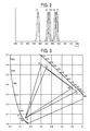
- FIG. 2 shows example emission spectrum of light emitted from each LED light source of the light source apparatus 10.
- FIG. 3 shows color coordinates of the emission spectrum shown in FIG. 2 plotted on the xy chromaticity diagram of CIE-XYZ color system defined as international color system by Commission Internationale de l'Eclairage (CIE).
- CIE Commission Internationale de l'Eclairage
- R1 is the main wavelength of the first red LED 100
- R2 is the main wavelength of the second red LED 130
- G1 is the main wavelength of the first green LED 110
- G2 is the main wavelength of the second green LED 140
- B is the main wavelength of the first blue LED 120.
- the spectral characteristics of R1, G1 and B in FIG. 2 can be expressed as a color triangle shown in FIG. 3 , in which coordinates corresponding to R1, G1 and B are plotted as the tops of the color triangle.
- the color triangle of R1, G1 and B is substantially matched to the color triangle of sRGB standard, which means the coordinates corresponding to R1, G1 and B are substantially matched to coordinates of the three primary colors of sRGB standard.
- the color reproduction performance of non-primary color may not be good enough using only the R1, G1 and B.
- Ye (yellow) which is a color between R1 and G1
- Ye (yellow) light component is not included in the light sources
- the Ye (yellow) light is generated by synthesizing the light of R1 and G1.
- the color reproduction performance of Ye (yellow) generated by synthesizing the light of R1 and G1 may not be good enough, which means the color reproduction performance of non-primary color may not be good enough.
- Ye light having a good level of reproduction performance can be generated by synthesizing the light of R2 and G2 having the wavelength relatively close to Ye in the emission spectrum compared to the wavelength of the light of R1 and G1.
- the wavelength of light of each R2 and G2 is also close to the wavelength of red (R) and green (G) emission spectrum of a high-pressure mercury vapor lamp used as a light source of a DLP projector.
- the spectral characteristics of R2, G2 and B shown in FIG. 2 can be expressed as a color triangle as shown in FIG. 3 using the coordinates corresponding to R2, G2 and B as the tops of the color triangle.
- non-primary color such as an image of Ye (yellow), which is a non-primary color between red (R) and green (G)
- the light having the wavelength for R2 and G2 respectively emitted from the second red LED 130 and the second green LED 140 can be preferably used.
- the ratio of light intensities of light emitted from each of the light sources which is defined R1/R2 and G1/G2, can be changed depending on image signals input to the image projection apparatus 1.
- FIG. 4 is a block diagram of a circuit for generating signals to control the ratio of light intensities of R1/R2 and G1/G2.
- a signal is input from a terminal a, and then processed towards a terminal b.
- the circuit shown in FIG. 4 can be included in the main controller 50 such as a processing circuit.
- the control signal may be generated using a route different from a route for image signal to be displayed by the image projection apparatus 1.
- the signals to control the ratio of light intensities of R1/R2 and G1/G2 can be generated as follows.
- An image signal is input from the terminal "a” and then separated into a luminance signal and a color component signal by a matrix 80 used as a signal separator.
- a motion detector 81 used as an image determiner, monitors a plurality of image frames to determine whether an image signal is a moving image or a still image.
- an average picture level (APL) detector 82 used as an average luminance level detector detects a luminance level of the image signal.
- a color component analyzer 83 used as a color profile analyzer analyzes color profile of image based on the color component signal. For example, the color component analyzer 83 analyzes colors from green (G) to red (R) for the image projection apparatus 1.
- a color saturation analyzer 84 used as a color saturation analyzer analyzes color saturation level or density level of color of image.
- an image contents determiner 85 used as an image contents determiner determines what image is displayed based on information of the moving image and/or still image and the APL level information extracted from the luminance signal, and color component information and saturation level information extracted from the color component signal. Then, the image contents determiner 85 determines the contents using a following determination matrix.
- the determination matrix can be set as follows. If the image is determined having conditions of still image, high APL , and high saturation, the image is determined as "presentation type image," which may be created as an image used for presentation purpose. If the image is determined having conditions of moving image (or still image), low APL, and low saturation, the image is determined as a "natural object image” such as photo, moving image, which may be an image of actual objects taken by a camera or the like.
- the light of each R1, R2, G1 and G2 is emitted with a substantially full power.
- the ratio of light intensities of R1/R2 and G1/G2 are variably controlled based on an analysis of color component.
- the light intensity of the light of G1 and G2 can be controlled by setting the intensity relationship of G1 > G2.
- the natural object image is tinted autumnal leaves of yellow green and yellow
- the light intensity of the light of G1 and G2 can be controlled by setting the intensity relationship of G1 ⁇ G2 and R1 ⁇ R2.
- an image signal is analyzed to determine components in signals.
- signal components close to R/G primary colors and signal components close to Ye color which can be generated by synthesizing the light of R and G, can be determined, and then the ratio of light intensities of R1/R2 and G1/G2 can be variably set.
- a control signal generator 86 generates the above-described control signal
- a light source drive circuit 87 converts the control signal to a signal that sets light ON of the light source, and controls the light source by transmitting the signal through the terminal b.
- FIG. 5 shows a profile of emission spectrum a high-pressure mercury vapor lamp (see profile K) of a comparison example 1 and the wavelengths of primary colors of RGB
- FIG. 6 shows color coordinates of light emitted from the high-pressure mercury vapor lamp having the emission spectrum of FIG. 5 on the xy chromaticity diagram of CIE-XYZ color system, wherein the high-pressure mercury vapor lamp is used as a light source of projectors.
- the emission spectrum of the high-pressure mercury vapor lamp is indicated by profile K in FIG. 5 .
- the light intensity at the wavelength of each of RGB primary color lights is not uniform.
- a wavelength used as the primary color of the high-pressure mercury vapor lamp may be shifted from the wavelength of primary color of the sRGB in view of the emission spectrum of the high-pressure mercury vapor lamp.
- an outer color triangle is a color triangle having the top coordinates of primary color of sRGB
- an inner color triangle is a color triangle for the high-pressure mercury vapor lamp used as the light source of projectors.
- the wavelength of green (G) light of the high-pressure mercury vapor lamp that contributes greatly for the brightness is set with a wavelength which is shifted to a short side compared to the wavelength of primary color of sRGB standard, and further, the wavelength of red (R) of the high-pressure mercury vapor lamp is set with a wavelength which is shifted to a long side from the wavelength of primary color of sRGB standard to maintain the reproduction performance of brightness and colors.
- the color coordinates of R and G primary colors set for the high-pressure mercury vapor lamp are deviated from the color coordinates of R and G primary colors of the color reproduction range of sRGB standard, and thereby when G and R of the high-pressure mercury vapor lamp are displayed as a single color, G light may become a color of dead grass, and R light may become vermilion color.
- FIG. 7 shows a profile of emission spectrum of a xenon lamp, which is a comparison example 2.
- the xenon lamp has an emission spectrum very close to the emission spectrum of the sunlight. Because the emission spectrum is relatively flat in the visible light range, the color reproduction performance is good at any colors having different wavelength, by which a good level of natural color reproduction performance can be obtained. However, because the xenon lamp is large and consumes high power, the xenon lamp may not be used as the light source of typical compact projectors.
- the light source apparatus 10 includes the red light emitting device such as the first red LED 100 to emit red light, the green light emitting device such as the first green LED 110 to emit green light, the blue light emitting device such as the first blue LED 120 to emit blue light, which are independent light emitting devices with each other.
- at least two light emitting devices of the red light emitting device, the green light emitting device, and the blue light emitting device include the first light source to emit the light of the primary color (e.g., first red LED 100, first green LED 110), and the second light source to emit the light having a wavelength deviated from the wavelength of the light of the primary color (e.g., second red LED 130, second green LED 140).
- At least the two light emitting devices of the red light emitting device, the green light emitting device, and the blue light emitting device can emit the primary color light and a light having a wavelength deviated from the primary color light, by which at least two types of light can be used for two lights selected from red, green, and blue lights.
- the wavelength range of light emitted from the two light emitting devices e.g., first red LED 100/second red LED 130, first green LED 110/second green LED 140
- the color reproduction performance of non-primary color between the red, green, and blue can be enhanced.
- each of the two light emitting devices includes the first light source (100, 110) and the second light source (130, 140), and when coordinates of wavelength of the red light emitting device (100, 130), the green light emitting device (110, 140) and the blue light emitting device (120) are plotted in a color coordinate system, two coordinates corresponding to two wavelength of the light emitted from the second light sources (130, 140) are between two coordinates corresponding to two wavelength of light emitted from the first light sources (100, 110), and the two coordinates corresponding to two wavelength of the light emitted from the second light sources (130, 140) are substantially on a line connecting the two coordinates of the light emitted from the first light sources (100, 110).
- each wavelength of the second light source of the two light emitting devices can be set close to a wavelength of non-primary color, by which the color reproduction performance of non-primary color can be enhanced.
- each of the first light sources (100, 110) of the at least two light emitting devices is a semiconductor light source that emits primary color light matched to sRGB standard of CIE-XYZ color system.
- the semiconductor light source can select a wavelength of emitting light, and thereby the semiconductor light source can emit a light having the wavelength of the primary color of sRGB standard.
- each of the second light sources (130, 140) of the at least two light emitting devices emits light having a wavelength deviated from the wavelength of primary color light emitted by the first light sources (100, 110) in a range from 1 nm to 20 nm.
- the wavelength range of the light source can be broaden within a range of 1 nm to 20 nm, by which the color reproduction performance of non-primary color can be enhanced.
- the above described light source apparatus 10 can be employed for the image projection apparatus 1.
- the image projection apparatus includes the light source apparatus 10, the light modulation element 30 to pass through or reflect light irradiated from the light source apparatus based on an image signal of a projection target image; and a projection optical system 40 to project an image passing through or reflecting the light modulation element on a screen.
- the image projection apparatus 1 includes a signal separator 80 to separate an image signal of the projection target image into a luminance signal and a color component signal; an image determiner 81 to determine whether the image is a moving image or a still image based on the luminance signal; an average luminance level detector 82 to detect an average luminance level of the image based on the luminance signal; a color profile analyzer 83 to analyze color profile based on the color component signal; a color saturation analyzer 84 to analyze color saturation based on the color component signal; an image contents determiner 85 to determine contents of the projection target image based on determination of the image determiner 81, determination of the average luminance level detector 82, analysis of the color profile analyzer 83, and analysis of the color saturation analyzer 84; an light intensity ratio determiner 86 to determine light intensity ratio of light emitted from the first light source and light emitted from the second light source based on the determination of the image contents determiner 85; and a light source controller (87) to control the first light sources and the second light sources
- the light source controller 87 controls a ratio of an emission time of light emitted from the first light source to an emission time of light emitted from the second light source, radiated to the light modulation element for one frame image, based on the light intensity ratio determined by the light intensity ratio determiner 86.
- the ratio of emission time of light emitted from the first light source to an emission time of light emitted from the second light source can be computed based the analysis of luminance of image signal and color components of the input image, and thereby colors can be generated efficiently, and the color reproduction performance can be enhanced.
- the image projection apparatus employing the light source apparatus, among the red light emitting device, the green light emitting device and the blue light emitting device, at least each of two light emitting devices including a first light source (100, 110) and a second light source (130, 140), in which the first light source (100, 110) emitting light of primary color having a wavelength, and the second light source (130, 140) emitting light having a wavelength deviated from the wavelength of the light of the primary color.
- two types of light can be secured for at least two of red, green, and blue light.
- the wavelength range of light emitted from the two light emitting devices e.g., first red LED 100/second red LED 130, first green LED 110/second green LED 140
- the color reproduction performance of non-primary color between the red, green, and blue can be enhanced, color reproduction performance of non-primary color between red, green, and blue can be enhanced.
Landscapes
- Engineering & Computer Science (AREA)
- Multimedia (AREA)
- Signal Processing (AREA)
- Physics & Mathematics (AREA)
- General Physics & Mathematics (AREA)
- Optics & Photonics (AREA)
- Projection Apparatus (AREA)
- Microelectronics & Electronic Packaging (AREA)
- General Engineering & Computer Science (AREA)
- Transforming Electric Information Into Light Information (AREA)
- Non-Portable Lighting Devices Or Systems Thereof (AREA)
Abstract
Description
- The present invention generally relates to a light source apparatus having separate light emitting devices for red light, green light, and blue light, and an image projection apparatus employing the light source apparatus.
- Image projection apparatuses include various types of projectors such as a digital light processing (DLP: registered trademark) projector, a liquid crystal display (LCD) projector, and so on. The projector may use a discharge lamp such as a high-pressure mercury vapor lamp as a light source, but a semiconductor light source or a solid-state light source such as a light emitting diode (LED) or a laser diode (LD) has been developed and can be used instead of the discharge lamp. For example,
JP-2012-008549-A - The high-pressure mercury vapor lamp has a specific emission spectrum characteristic such that the blue (B) component is strong while the green (G) and red (R) components are weak, by which the lamp emits light with a specific color reproduction performance. The Commission Internationale de l'Eclairage (CIE) defines an international color system such as CIE-XYZ color system, such that the color coordinates can be set in the xy chromaticity diagram, and sRGB (standard RGB) is used as the international Standard, in which a color triangle is defined by connecting the tops of R, G and B defined by sRGB.
- Compared to the color triangle of sRGB, the green light of the high-pressure mercury vapor lamp is shifted toward yellowish green, and the red light of the high-pressure mercury vapor lamp is shifted toward vermilion, as shown in
FIG. 6 . Therefore, to secure the intensity of green light and red light for the projector using the high-pressure mercury vapor lamp, a light having a wavelength deviated from the wavelength of the primary colors defined by sRGB standard is used as primary color light. As a consequence, however, the color reproduction performance of the projector using the high-pressure mercury vapor lamp deteriorates. - In contrast, projectors employing the semiconductor light sources can use separate red, green, and blue light sources, and each of the light sources can be configured to emit a light beam having a specific wavelength. Therefore, compared to projectors using a high-pressure mercury vapor lamp as the light source, the wavelengths of light beams emitted from each of the light source, used as the primary color, can be more closely matched to the wavelength of the primary color light as defined by sRGB standard. Therefore, a color triangle of the semiconductor light sources on the color coordinates of the xy chromaticity diagram can be set closer to the sRGB standard color triangle, thereby improving color reproduction performance and enlarging a color reproduction area. For this reason, the light sources for projectors may be changed from the high-pressure mercury vapor lamp to the semiconductor light source in the future. It should be noted that herein the term "primary colors" mean colors that become the sources of all colors, wherein the primary colors of light are red (R), green (G), and blue (B) light, and almost any color can be reproduced using some combination of the three primary colors.
- As for the projectors using the semiconductor light sources, the color triangle defined by the wavelength of each of the light sources used as the primary colors can be set close to the color triangle of sRGB standard on the color coordinates, thereby providing color reproduction performance superior to projectors using the above-mentioned discharge lamp such as the high-pressure mercury vapor lamp. However, the color reproduction performance of non-primary colors generated by a combination of light of each of the light sources may not always be satisfactory.
- In
JP-2012-008549-A - However, in the configuration of
JP-2012-008549-A - The present invention is directed to a light source apparatus to generate non-primary color light effectively. The light source apparatus includes a red light emitting device such as a light emitting diode to emit red light; a green light emitting device such as a light emitting diode to emit green light; a blue light emitting device such as a light emitting diode to emit blue light, each of the red light emitting device, the green light emitting device, and the blue light emitting device disposed separately from any other. Among the red light emitting device, the green light emitting device and the blue light emitting device, at least each of two light emitting devices including a first light source such as a light emitting diode and a second light source such as a light emitting diode, the first light source emitting a light having a wavelength of a primary color, and the second light source emitting light having a wavelength deviated from the wavelength of the light of the primary color.
- A more complete appreciation of the disclosure and many of the attendant advantages and features thereof can be readily obtained and understood from the following detailed description with reference to the accompanying drawings, wherein:
-
FIG. 1 is a schematic configuration of a light source apparatus and an image projection apparatus according to an example embodiment of the present invention -
FIG. 2 shows example profiles of emission spectrum of light emitted from each LED of the light source apparatus ofFIG. 1 ; -
FIG. 3 shows color coordinates of light having the emission spectrum shown inFIG. 2 plotted on the xy chromaticity diagram of CIE-XYZ color system; -
FIG. 4 is a block diagram of a circuit for generating signals for controlling a ratio of light intensities for R1/R2 and G1/G2; -
FIG. 5 shows an example emission spectrum of a high-pressure mercury vapor lamp of a comparison example and wavelength of primary colors of RGB; -
FIG. 6 shows color coordinates of primary color lights of the high-pressure mercury vapor lamp used as a light source of a projector having the emission spectrum ofFIG. 5 plotted on the xy chromaticity diagram of CIE-XYZ color system compared with the color coordinates of primary color lights of sRGB; and -
FIG. 7 shows a profile of emission spectrum of a xenon lamp of a comparison example. - The accompanying drawings are intended to depict exemplary embodiments of the present invention and should not be interpreted to limit the scope thereof. The accompanying drawings are not to be considered as drawn to scale unless explicitly noted, and identical or similar reference numerals designate identical or similar components throughout the several views.
- A description is now given of exemplary embodiments of the present invention. It should be noted that although such terms as first, second, etc. may be used herein to describe various elements, components, regions, layers and/or sections, it should be understood that such elements, components, regions, layers and/or sections are not limited thereby because such terms are relative, that is, used only to distinguish one element, component, region, layer or section from another region, layer or section. Thus, for example, a first element, component, region, layer or section discussed below could be termed a second element, component, region, layer or section without departing from the teachings of the present invention.
- In addition, it should be noted that the terminology used herein is for the purpose of describing particular embodiments only and is not intended to be limiting of the present invention. Thus, for example, as used herein, the singular forms "a", "an" and "the" are intended to include the plural forms as well, unless the context clearly indicates otherwise. Moreover, the terms "includes" and/or "including", when used in this specification, specify the presence of stated features, integers, steps, operations, elements, and/or components, but do not preclude the presence or addition of one or more other features, integers, steps, operations, elements, components, and/or groups thereof.
- Furthermore, although in describing views shown in the drawings, specific terminology is employed for the sake of clarity, the present disclosure is not limited to the specific terminology so selected and it is to be understood that each specific element includes all technical equivalents that, have a similar function, operate in a similar manner, and achieve a similar result. Referring now to the drawings, apparatuses or systems according to example embodiments of the present invention are described hereinafter.
- A description is given of a light source apparatus and an image projection apparatus including the light source apparatus according to an example embodiment of the present invention with reference to the drawings.
FIG. 1 is a schematic configuration of a light source apparatus and an image projection apparatus 1 using the light source apparatus according to an example embodiment of the present invention. The image projection apparatus 1 may be, for example, a digital light processing (DLP : registered trademark) projector. As illustrated inFIG. 1 , the image projection apparatus 1 includes, for example, alight source apparatus 10, arelay lens 20, alight modulation element 30, aprojection lens 40, amain controller 50, alight source controller 60, and a lightmodulation element driver 70. - The
light modulation element 30 is, for example, a reflection type light modulation element including a large number of micro mirrors arranged on a plane. Theprojection lens 40, used as a projection optical system, projects images onto thescreen 200. Themain controller 50 controls the image projection apparatus 1 as a whole. Thelight source controller 60 controls each LED light source of thelight source apparatus 10. The lightmodulation element driver 70 controls the micro mirrors of thelight modulation element 30. In this disclosure, thelight modulation element 30 employs a semiconductor device known as a digital micro-mirror device (DMD : registered trademark) having a large number of micro mirrors arranged in a matrix to be radiated by the light coming from the light source, and an angle of the light reflection face of each of the micro mirrors can be controlled. Thelight modulation element 30 is not limited to the DMD, but other devices such as a pass-through or reflection type liquid crystal micro display can be used. - The
light source apparatus 10 includes, for example, a red light emitting device that emits red (R) light, a green light emitting device that emits green (G) light, and a blue light emitting device that emits blue (B) light, wherein the red light emitting device, the green light emitting device, and the blue light emitting device are independent light emitting device with each other. Each of the light emitting devices includes, for example, a first light source employing a semiconductor light source such as a light emitting diode (LED) that can respectively emit the light of three primary colors of R(red), G(green), and B(blue) having the substantially same wavelength of the corresponding three primary colors of sRGB standard. - For example, the red light emitting device includes a first
red LED 100 as the first light source of the red light emitting device, the green light emitting device includes a firstgreen LED 110 as the first light source of the green light emitting device, and the blue light emitting device includes a firstblue LED 120 as the first light source of the blue light emitting device. Further, among the three light emitting devices, for example, the red light emitting device includes a second light source using the semiconductor light source such as LED, and the green light emitting device further includes a second light source using the semiconductor light source such as LED. For example, the red light emitting device includes a secondred LED 130 as the second light source of the red light emitting device that emits a light having a wavelength deviated from the wavelength of the light of primary color emitted from the firstred LED 100. Further, the green light emitting device includes a secondgreen LED 140 as the second light source of the green light emitting device that emits a light having a wavelength deviated from the wavelength of the light of the primary color emitted from the firstgreen LED 110. In this configuration, the deviation of wavelength of light emittable from the second light source from the wavelength of the light emittable from the first light source (i.e. primary color light) is, for example, in a range of 1 nm to 20 nm, and preferably 10 nm to 15 nm. AlthoughFIG. 1 shows a configuration that the blue light emitting device does not include the second light source, the blue light emitting device can include a second light source. - The
light source apparatus 10 further includescollimator lenses dichroic mirrors 151 to 154. Each of thecollimator lenses LEDs dichroic mirrors 151 to 154 reflects a light having a specific wavelength and passes through a light having other wavelength. - In the
light source apparatus 10, the red light emitted from the firstred LED 100 is collimated by thecollimator lens 101, passes through thedichroic mirror 151, and is then reflected by thedichroic mirror 152. Further, the green light emitted from the firstgreen LED 110 is collimated by thecollimator lens 111, passes through thedichroic mirror 153, and is then reflected by thedichroic mirror 154. Further, the blue light emitted from the firstblue LED 120 is collimated by thecollimator lens 121, and passes through thedichroic mirrors - The second
red LED 130 emits a red light (e.g., 624 nm) deviated from the wavelength of the first red LED 100 (e.g., 636 nm), which is shifted toward green color. The red light emitted from the secondred LED 130 is collimated by thecollimator lens 131, and reflected by thedichroic mirrors green LED 140 emits a green light (e.g., 577 nm) deviated from the wavelength of the first green LED 110 (565 nm), which is shifted toward red color. The green light emitted from the secondgreen LED 140 is collimated by thecollimator lens 141, and reflected by thedichroic mirrors - As for the
light source apparatus 10, the lights emitted from the LED light sources are synthesized as a synthesized light, and the synthesized light irradiates thelight modulation element 30 through therelay lens 20. For example, thelight modulation element 30 has micro-mirror matrix such as several tens of µm-sized mirrors arranged in a matrix pattern of 480, 000 mirrors to 207 million mirrors. The lightmodulation element driver 70 drives each of the micro mirrors using drive signals to control the light reflection for each of display pixels to project a full color image. The full color image generated by thelight modulation element 30 is enlarged and projected onto thescreen 200 via theprojection lens 40. -
FIG. 2 shows example emission spectrum of light emitted from each LED light source of thelight source apparatus 10.FIG. 3 shows color coordinates of the emission spectrum shown inFIG. 2 plotted on the xy chromaticity diagram of CIE-XYZ color system defined as international color system by Commission Internationale de l'Eclairage (CIE). For example, inFIGs. 2 and 3 , R1 is the main wavelength of the firstred LED 100, R2 is the main wavelength of the secondred LED 130, G1 is the main wavelength of the firstgreen LED 110, G2 is the main wavelength of the secondgreen LED 140, and B is the main wavelength of the firstblue LED 120. - The spectral characteristics of R1, G1 and B in
FIG. 2 can be expressed as a color triangle shown inFIG. 3 , in which coordinates corresponding to R1, G1 and B are plotted as the tops of the color triangle. The color triangle of R1, G1 and B is substantially matched to the color triangle of sRGB standard, which means the coordinates corresponding to R1, G1 and B are substantially matched to coordinates of the three primary colors of sRGB standard. However, the color reproduction performance of non-primary color may not be good enough using only the R1, G1 and B. For example, when Ye (yellow), which is a color between R1 and G1, is to be generated and displayed, because Ye (yellow) light component is not included in the light sources, the Ye (yellow) light is generated by synthesizing the light of R1 and G1. However, the color reproduction performance of Ye (yellow) generated by synthesizing the light of R1 and G1 may not be good enough, which means the color reproduction performance of non-primary color may not be good enough. - Based on the research of the inventor, it is found that Ye light having a good level of reproduction performance can be generated by synthesizing the light of R2 and G2 having the wavelength relatively close to Ye in the emission spectrum compared to the wavelength of the light of R1 and G1. The wavelength of light of each R2 and G2 is also close to the wavelength of red (R) and green (G) emission spectrum of a high-pressure mercury vapor lamp used as a light source of a DLP projector. The spectral characteristics of R2, G2 and B shown in
FIG. 2 can be expressed as a color triangle as shown inFIG. 3 using the coordinates corresponding to R2, G2 and B as the tops of the color triangle. Therefore, when generating non-primary color such as an image of Ye (yellow), which is a non-primary color between red (R) and green (G), the light having the wavelength for R2 and G2 respectively emitted from the secondred LED 130 and the secondgreen LED 140 can be preferably used. - Further, the ratio of light intensities of light emitted from each of the light sources, which is defined R1/R2 and G1/G2, can be changed depending on image signals input to the image projection apparatus 1.
-
FIG. 4 is a block diagram of a circuit for generating signals to control the ratio of light intensities of R1/R2 and G1/G2. In this block diagram, a signal is input from a terminal a, and then processed towards a terminal b. The circuit shown inFIG. 4 can be included in themain controller 50 such as a processing circuit. The control signal may be generated using a route different from a route for image signal to be displayed by the image projection apparatus 1. - The signals to control the ratio of light intensities of R1/R2 and G1/G2 can be generated as follows. An image signal is input from the terminal "a" and then separated into a luminance signal and a color component signal by a
matrix 80 used as a signal separator. - A
motion detector 81, used as an image determiner, monitors a plurality of image frames to determine whether an image signal is a moving image or a still image. Further, as for the luminance signal, an average picture level (APL)detector 82 used as an average luminance level detector detects a luminance level of the image signal. As for the color component signal, acolor component analyzer 83 used as a color profile analyzer analyzes color profile of image based on the color component signal. For example, thecolor component analyzer 83 analyzes colors from green (G) to red (R) for the image projection apparatus 1. Further, acolor saturation analyzer 84 used as a color saturation analyzer analyzes color saturation level or density level of color of image. Further, an image contents determiner 85 used as an image contents determiner determines what image is displayed based on information of the moving image and/or still image and the APL level information extracted from the luminance signal, and color component information and saturation level information extracted from the color component signal. Then, the image contents determiner 85 determines the contents using a following determination matrix. - For example, the determination matrix can be set as follows. If the image is determined having conditions of still image, high APL , and high saturation, the image is determined as "presentation type image," which may be created as an image used for presentation purpose. If the image is determined having conditions of moving image (or still image), low APL, and low saturation, the image is determined as a "natural object image" such as photo, moving image, which may be an image of actual objects taken by a camera or the like.
- If it is determined that an image is the presentation type image based on the above mentioned determination matrix, the light of each R1, R2, G1 and G2 is emitted with a substantially full power. In contrast, if it is determined that an image is a natural object image based on the determination matrix, the ratio of light intensities of R1/R2 and G1/G2 are variably controlled based on an analysis of color component.
- For example, if the natural object image is a green object on a mountain, the light intensity of the light of G1 and G2 can be controlled by setting the intensity relationship of G1 > G2. Further, for example, if the natural object image is tinted autumnal leaves of yellow green and yellow, the light intensity of the light of G1 and G2 can be controlled by setting the intensity relationship of G1 < G2 and R1 < R2. In this process, an image signal is analyzed to determine components in signals. Specifically, based on the analysis of the image signal, signal components close to R/G primary colors and signal components close to Ye color, which can be generated by synthesizing the light of R and G, can be determined, and then the ratio of light intensities of R1/R2 and G1/G2 can be variably set.
- Then, a
control signal generator 86 generates the above-described control signal, and a lightsource drive circuit 87 converts the control signal to a signal that sets light ON of the light source, and controls the light source by transmitting the signal through the terminal b. -
FIG. 5 shows a profile of emission spectrum a high-pressure mercury vapor lamp (see profile K) of a comparison example 1 and the wavelengths of primary colors of RGB, andFIG. 6 shows color coordinates of light emitted from the high-pressure mercury vapor lamp having the emission spectrum ofFIG. 5 on the xy chromaticity diagram of CIE-XYZ color system, wherein the high-pressure mercury vapor lamp is used as a light source of projectors. - As illustrated in a comparison example of
FIG. 5 , the emission spectrum of the high-pressure mercury vapor lamp is indicated by profile K inFIG. 5 . In the profile K, the light intensity at the wavelength of each of RGB primary color lights is not uniform. Because typical projectors demand a given level of brightness, a wavelength used as the primary color of the high-pressure mercury vapor lamp may be shifted from the wavelength of primary color of the sRGB in view of the emission spectrum of the high-pressure mercury vapor lamp. As shown in the chromaticity diagram ofFIG. 6 , an outer color triangle is a color triangle having the top coordinates of primary color of sRGB, and an inner color triangle is a color triangle for the high-pressure mercury vapor lamp used as the light source of projectors. - As for the projectors using the high-pressure mercury vapor lamp as the light source, the wavelength of green (G) light of the high-pressure mercury vapor lamp that contributes greatly for the brightness is set with a wavelength which is shifted to a short side compared to the wavelength of primary color of sRGB standard, and further, the wavelength of red (R) of the high-pressure mercury vapor lamp is set with a wavelength which is shifted to a long side from the wavelength of primary color of sRGB standard to maintain the reproduction performance of brightness and colors. However, the color coordinates of R and G primary colors set for the high-pressure mercury vapor lamp are deviated from the color coordinates of R and G primary colors of the color reproduction range of sRGB standard, and thereby when G and R of the high-pressure mercury vapor lamp are displayed as a single color, G light may become a color of dead grass, and R light may become vermilion color.
-
FIG. 7 shows a profile of emission spectrum of a xenon lamp, which is a comparison example 2. The xenon lamp has an emission spectrum very close to the emission spectrum of the sunlight. Because the emission spectrum is relatively flat in the visible light range, the color reproduction performance is good at any colors having different wavelength, by which a good level of natural color reproduction performance can be obtained. However, because the xenon lamp is large and consumes high power, the xenon lamp may not be used as the light source of typical compact projectors. - In the above described example embodiment, the
light source apparatus 10 includes the red light emitting device such as the firstred LED 100 to emit red light, the green light emitting device such as the firstgreen LED 110 to emit green light, the blue light emitting device such as the firstblue LED 120 to emit blue light, which are independent light emitting devices with each other. Further, at least two light emitting devices of the red light emitting device, the green light emitting device, and the blue light emitting device include the first light source to emit the light of the primary color (e.g., firstred LED 100, first green LED 110), and the second light source to emit the light having a wavelength deviated from the wavelength of the light of the primary color (e.g., secondred LED 130, second green LED 140). - With this configuration, as described above, at least the two light emitting devices of the red light emitting device, the green light emitting device, and the blue light emitting device can emit the primary color light and a light having a wavelength deviated from the primary color light, by which at least two types of light can be used for two lights selected from red, green, and blue lights. Further, because the wavelength range of light emitted from the two light emitting devices (e.g., first
red LED 100/secondred LED 130, firstgreen LED 110/second green LED 140) is broader compared to only emitting light of the primary color light, the color reproduction performance of non-primary color between the red, green, and blue can be enhanced. - In the above described
light source apparatus 10 when each of the two light emitting devices includes the first light source (100, 110) and the second light source (130, 140), and when coordinates of wavelength of the red light emitting device (100, 130), the green light emitting device (110, 140) and the blue light emitting device (120) are plotted in a color coordinate system, two coordinates corresponding to two wavelength of the light emitted from the second light sources (130, 140) are between two coordinates corresponding to two wavelength of light emitted from the first light sources (100, 110), and the two coordinates corresponding to two wavelength of the light emitted from the second light sources (130, 140) are substantially on a line connecting the two coordinates of the light emitted from the first light sources (100, 110). With this configuration, as described above, each wavelength of the second light source of the two light emitting devices can be set close to a wavelength of non-primary color, by which the color reproduction performance of non-primary color can be enhanced. - In the above described
light source apparatus 10 each of the first light sources (100, 110) of the at least two light emitting devices is a semiconductor light source that emits primary color light matched to sRGB standard of CIE-XYZ color system. With this configuration, as described above, in contrast to conventional high-pressure mercury vapor lamps which are difficult to emit a light having the wavelength of the primary color of sRGB standard, the semiconductor light source can select a wavelength of emitting light, and thereby the semiconductor light source can emit a light having the wavelength of the primary color of sRGB standard. - In the above described
light source apparatus 10, each of the second light sources (130, 140) of the at least two light emitting devices emits light having a wavelength deviated from the wavelength of primary color light emitted by the first light sources (100, 110) in a range from 1 nm to 20 nm. With this configuration, as described above, the wavelength range of the light source can be broaden within a range of 1 nm to 20 nm, by which the color reproduction performance of non-primary color can be enhanced. - The above described
light source apparatus 10 can be employed for the image projection apparatus 1. The image projection apparatus includes thelight source apparatus 10, thelight modulation element 30 to pass through or reflect light irradiated from the light source apparatus based on an image signal of a projection target image; and a projectionoptical system 40 to project an image passing through or reflecting the light modulation element on a screen. With this configuration, as described above, the color reproduction performance of non-primary color can be enhanced while maintaining luminance of projected image. - The image projection apparatus 1 includes a
signal separator 80 to separate an image signal of the projection target image into a luminance signal and a color component signal; animage determiner 81 to determine whether the image is a moving image or a still image based on the luminance signal; an averageluminance level detector 82 to detect an average luminance level of the image based on the luminance signal; acolor profile analyzer 83 to analyze color profile based on the color component signal; acolor saturation analyzer 84 to analyze color saturation based on the color component signal; an image contents determiner 85 to determine contents of the projection target image based on determination of theimage determiner 81, determination of the averageluminance level detector 82, analysis of thecolor profile analyzer 83, and analysis of thecolor saturation analyzer 84; an lightintensity ratio determiner 86 to determine light intensity ratio of light emitted from the first light source and light emitted from the second light source based on the determination of theimage contents determiner 85; and a light source controller (87) to control the first light sources and the second light sources based on the light intensity ratio determined by the lightintensity ratio determiner 86. With this configuration, as described above, based on signals of a projection target image, signal components close to primary colors and signal components close to non-primary colors can be analyzed, and then a ratio of light intensities between the light emitted from light the first light source and the light emitted from the second light source can be determined depending on the analysis of signal components of colors. Therefore, depending on types of projection target image, thelight source apparatus 10 can be controlled effectively. - In the image projection apparatus 1, the
light source controller 87 controls a ratio of an emission time of light emitted from the first light source to an emission time of light emitted from the second light source, radiated to the light modulation element for one frame image, based on the light intensity ratio determined by the lightintensity ratio determiner 86. - With this configuration, as described above, the ratio of emission time of light emitted from the first light source to an emission time of light emitted from the second light source can be computed based the analysis of luminance of image signal and color components of the input image, and thereby colors can be generated efficiently, and the color reproduction performance can be enhanced.
- In the above described light source apparatus and the image projection apparatus employing the light source apparatus, among the red light emitting device, the green light emitting device and the blue light emitting device, at least each of two light emitting devices including a first light source (100, 110) and a second light source (130, 140), in which the first light source (100, 110) emitting light of primary color having a wavelength, and the second light source (130, 140) emitting light having a wavelength deviated from the wavelength of the light of the primary color. With this configuration, two types of light can be secured for at least two of red, green, and blue light. Further, because the wavelength range of light emitted from the two light emitting devices (e.g., first
red LED 100/secondred LED 130, firstgreen LED 110/second green LED 140) is broader compared to only emitting light of the primary color light, the color reproduction performance of non-primary color between the red, green, and blue can be enhanced, color reproduction performance of non-primary color between red, green, and blue can be enhanced. - Numerous additional modifications and variations are possible in light of the above teachings. It is therefore to be understood that, within the scope of the appended claims, the disclosure of the present invention may be practiced otherwise than as specifically described herein. For example, elements and/or features of different examples and illustrative embodiments may be combined each other and/or substituted for each other within the scope of this disclosure and appended claims.
Claims (7)
- A light source apparatus (10) comprising:a red light emitting device (100, 130) to emit red light;a green light emitting device (110, 140) to emit green light; anda blue light emitting device (120) to emit blue light, each of the red light emitting device, the green light emitting device, and the blue light emitting device disposed separately from any other,at least two of the light emitting devices each including a first light source (100, 110) emitting light of having a wavelength of a light of primary color, and a second light source (130, 140) emitting light having a wavelength deviated from the wavelength of the light of the primary color emitted from the first light source.
- The light source apparatus (10) of claim 1, wherein, when each of the two light emitting devices includes the first light source (100, 110) and the second light source (130, 140), and when coordinates of wavelengths of light emitted by the red light emitting device (100, 130), the green light emitting device (110, 140) and the blue light emitting device (120) are plotted in a color coordinate system, two coordinates corresponding to two wavelengths of the light emitted from the second light sources (130, 140) are between two coordinates corresponding to two wavelength of light emitted from the first light sources (100, 110), and the two coordinates corresponding to two wavelength of the light emitted from the second light sources (130, 140) are on a line connecting the two coordinates of the light emitted from the first light sources (100, 110).
- The light source apparatus (10) of claims 1 or 2, wherein each of the first light sources (100, 110) of the at least two light emitting devices is a semiconductor light source that emits primary color light matched to sRGB standard of the CIE-XYZ color system.
- The light source apparatus (10) of any one of claims 1 to 3, wherein each of the second light sources (130, 140) of the at least two light emitting devices emits light having a wavelength deviated from the wavelength of primary color light emitted by the first light sources (100, 110) in a range of from 1 nm to 20 nm.
- An image projection apparatus comprising:the light source apparatus (10) of any one of claims 1 to 3;a light modulation element (30) to pass through or reflect light irradiated from the light source apparatus based on an image signal of a projection target image; anda projection optical system (40) to project an image passing through or reflected by the light modulation element on a screen.
- The image projection apparatus of claim 5 further comprising:a signal separator (80) to separate an image signal of the projection target image into a luminance signal and a color component signal;an image determiner (81) to determine whether the image is a moving image or a still image based on the luminance signal;an average luminance level detector (82) to detect an average luminance level of the image based on the luminance signal;a color profile analyzer (83) to analyze color profile based on the color component signal;a color saturation analyzer (84) to analyze color saturation based on the color component signal;an image contents determiner (85) to determine contents of the projection target image based on determination of the image determiner (81), determination of the average luminance level detector (82), analysis of the color profile analyzer (83), and analysis of the color saturation analyzer (84);a light intensity ratio determiner (86) to determine light intensity ratio of light emitted from the first light sources and light emitted from the second light sources based on the determination of the image contents determiner (85); anda light source controller (87) to control the first light sources and the second light sources based on the light intensity ratio determined by the light intensity ratio determiner (86).
- The image projection apparatus of claim 6, wherein the light source controller (87) controls a ratio of an emission time of light emitted from the first light sources to an emission time of light emitted from the second light sources radiated onto the light modulation element for one frame image, based on the light intensity ratio determined by the light intensity ratio determiner (86).
Applications Claiming Priority (1)
| Application Number | Priority Date | Filing Date | Title |
|---|---|---|---|
| JP2012151641A JP6086282B2 (en) | 2012-07-05 | 2012-07-05 | Image projection device |
Publications (3)
| Publication Number | Publication Date |
|---|---|
| EP2683160A2 true EP2683160A2 (en) | 2014-01-08 |
| EP2683160A3 EP2683160A3 (en) | 2014-09-17 |
| EP2683160B1 EP2683160B1 (en) | 2016-01-13 |
Family
ID=48745629
Family Applications (1)
| Application Number | Title | Priority Date | Filing Date |
|---|---|---|---|
| EP13171539.3A Not-in-force EP2683160B1 (en) | 2012-07-05 | 2013-06-11 | Light source apparatus and image projection apparatus |
Country Status (4)
| Country | Link |
|---|---|
| US (1) | US9010937B2 (en) |
| EP (1) | EP2683160B1 (en) |
| JP (1) | JP6086282B2 (en) |
| CN (1) | CN103529630B (en) |
Cited By (1)
| Publication number | Priority date | Publication date | Assignee | Title |
|---|---|---|---|---|
| US11404010B2 (en) | 2018-09-21 | 2022-08-02 | Appotronics Corporation Limited | Display apparatus, method for controlling same, and computer-readable storage medium |
Families Citing this family (15)
| Publication number | Priority date | Publication date | Assignee | Title |
|---|---|---|---|---|
| US9607821B2 (en) * | 2011-09-13 | 2017-03-28 | Osram Sylvania Inc. | Modified spectrum incandescent lamp |
| US9104038B2 (en) * | 2013-04-25 | 2015-08-11 | Microvision, Inc. | Multiple laser drive method, apparatus and system |
| CN105025279B (en) * | 2014-04-24 | 2017-03-01 | 深圳市绎立锐光科技开发有限公司 | A kind of light-source system and projection display equipment |
| CN105467732B (en) * | 2014-07-31 | 2018-12-04 | 欧司朗有限公司 | The light source module of optical projection apparatus and optical projection apparatus comprising light source module |
| CN104122742A (en) * | 2014-08-01 | 2014-10-29 | 杭州瑾丽光电科技有限公司 | Laser hybrid light source projector and light source device thereof |
| CN105739226B (en) * | 2014-12-08 | 2019-06-21 | 深圳光峰科技股份有限公司 | Projection system |
| US9810891B2 (en) * | 2015-04-15 | 2017-11-07 | Christie Digital Systems Usa, Inc. | Dual light source enhanced integration system |
| CN107703705A (en) * | 2016-08-09 | 2018-02-16 | 深圳市光峰光电技术有限公司 | Light-source system and projector equipment |
| JP6819135B2 (en) * | 2016-08-24 | 2021-01-27 | セイコーエプソン株式会社 | Lighting equipment and projector |
| CN108279548B (en) * | 2017-01-06 | 2021-02-02 | 深圳光峰科技股份有限公司 | Projection system |
| CN110007550B (en) | 2018-01-04 | 2021-11-05 | 深圳光峰科技股份有限公司 | Light source system and projection equipment |
| TWI809249B (en) * | 2020-02-11 | 2023-07-21 | 揚明光學股份有限公司 | Illumination system and fabrication method thereof and projector |
| EP4168708A4 (en) * | 2020-06-23 | 2025-05-21 | Luminus, Inc. | Light-emitting systems with double primary red LEDs |
| CN111624841B (en) * | 2020-06-24 | 2022-02-01 | 成都极米科技股份有限公司 | Mixed light source system and projection display equipment |
| CN112305845A (en) * | 2020-11-13 | 2021-02-02 | 歌尔光学科技有限公司 | Projection light path and projection equipment |
Citations (1)
| Publication number | Priority date | Publication date | Assignee | Title |
|---|---|---|---|---|
| JP2012008549A (en) | 2010-05-27 | 2012-01-12 | Panasonic Corp | Light source device and illuminating device using the same, and image display device |
Family Cites Families (17)
| Publication number | Priority date | Publication date | Assignee | Title |
|---|---|---|---|---|
| JP2001092014A (en) | 1999-09-22 | 2001-04-06 | Nec Corp | Projector device and method for obstacle recognition |
| JP4167100B2 (en) | 2003-03-20 | 2008-10-15 | 株式会社リコー | Image processing apparatus, image forming apparatus, image processing method, computer program, and recording medium |
| US7159987B2 (en) * | 2003-04-21 | 2007-01-09 | Seiko Epson Corporation | Display device, lighting device and projector |
| JP2004325630A (en) * | 2003-04-23 | 2004-11-18 | Seiko Epson Corp | Projection display device |
| JP4254672B2 (en) * | 2004-09-21 | 2009-04-15 | 株式会社ニコン | Portable information equipment |
| JP4158761B2 (en) | 2004-11-26 | 2008-10-01 | 株式会社ニコン | Projector device |
| US8454172B2 (en) | 2004-11-26 | 2013-06-04 | Nikon Corporation | Projector device |
| JP5376751B2 (en) * | 2005-12-15 | 2013-12-25 | シャープ株式会社 | projector |
| JP2008107653A (en) * | 2006-10-26 | 2008-05-08 | Optrex Corp | Drive unit having gamma correction function |
| US7905605B2 (en) * | 2006-12-13 | 2011-03-15 | Koninklijke Philips Electronics N.V. | Multi-primary LED projection system |
| JP4232826B2 (en) * | 2007-01-22 | 2009-03-04 | セイコーエプソン株式会社 | LASER LIGHT SOURCE DEVICE, MONITOR DEVICE USING SAME, AND IMAGE DISPLAY DEVICE |
| TWI330296B (en) * | 2007-05-25 | 2010-09-11 | Young Optics Inc | Light source module |
| US8083378B2 (en) | 2007-09-18 | 2011-12-27 | Seiko Epson Corporation | Single color LED clusters for image generation |
| JP5150183B2 (en) * | 2007-09-26 | 2013-02-20 | 三洋電機株式会社 | Projection display device |
| EP2463713B1 (en) * | 2009-09-02 | 2015-04-22 | NEC Display Solutions, Ltd. | Illuminating device and projection display device using same |
| JP2011237614A (en) * | 2010-05-11 | 2011-11-24 | Sanyo Electric Co Ltd | Projection type image display device |
| CN102520571B (en) | 2011-11-04 | 2014-08-06 | 深圳市光峰光电技术有限公司 | Light-emitting device and projection system |
-
2012
- 2012-07-05 JP JP2012151641A patent/JP6086282B2/en not_active Expired - Fee Related
-
2013
- 2013-05-29 US US13/904,521 patent/US9010937B2/en not_active Expired - Fee Related
- 2013-06-11 EP EP13171539.3A patent/EP2683160B1/en not_active Not-in-force
- 2013-06-26 CN CN201310261089.2A patent/CN103529630B/en not_active Expired - Fee Related
Patent Citations (1)
| Publication number | Priority date | Publication date | Assignee | Title |
|---|---|---|---|---|
| JP2012008549A (en) | 2010-05-27 | 2012-01-12 | Panasonic Corp | Light source device and illuminating device using the same, and image display device |
Cited By (1)
| Publication number | Priority date | Publication date | Assignee | Title |
|---|---|---|---|---|
| US11404010B2 (en) | 2018-09-21 | 2022-08-02 | Appotronics Corporation Limited | Display apparatus, method for controlling same, and computer-readable storage medium |
Also Published As
| Publication number | Publication date |
|---|---|
| CN103529630B (en) | 2015-09-02 |
| CN103529630A (en) | 2014-01-22 |
| JP2014016381A (en) | 2014-01-30 |
| EP2683160B1 (en) | 2016-01-13 |
| JP6086282B2 (en) | 2017-03-01 |
| EP2683160A3 (en) | 2014-09-17 |
| US9010937B2 (en) | 2015-04-21 |
| US20140009692A1 (en) | 2014-01-09 |
Similar Documents
| Publication | Publication Date | Title |
|---|---|---|
| US9010937B2 (en) | Light source apparatus and image projection apparatus | |
| KR101623004B1 (en) | Light source unit and projector | |
| US9081268B2 (en) | Lighting device and projection-type display apparatus including lighting device | |
| CN103018864B (en) | Fluorescent agent device, light source system and projection equipment suitable for fluorescent agent device | |
| JP3971717B2 (en) | Projector including a narrow-band spectral light source to supplement a broadband spectral light source | |
| CN106292142B (en) | A kind of light emitting device and its light-emitting control method, projection device | |
| CN105223761B (en) | Projection device and illumination system | |
| US20110292349A1 (en) | Light source device, lighting device and image display device using such light device | |
| KR101502679B1 (en) | Light source device and projector | |
| TWI584049B (en) | Light combining control system | |
| US9429761B2 (en) | Color synthesis optical element, projection-type display device using same, and method for controlling display thereof | |
| JP2016224304A (en) | Light source device, projection display device, and light generation method | |
| TW201137501A (en) | Light source unit and projector | |
| WO2016161934A1 (en) | Projection system and method for controlling color gamut thereof | |
| US20130083294A1 (en) | Illumination system and projection apparatus | |
| KR20030038083A (en) | Illumination system and projection system employing it | |
| JP2015166787A (en) | Light source device and projection device | |
| CN111812930B (en) | Projection device, projection control device, and recording medium | |
| CN111247795A (en) | Enhanced white light for projection lighting | |
| WO2016161933A1 (en) | Projection display system and control method therefor | |
| US9910347B2 (en) | Image display apparatus and image generation method | |
| JP6820703B2 (en) | Light source device and projection device | |
| EP3203732A1 (en) | Projection-type image display device | |
| KR20130021259A (en) | Light source controling apparatus for projector and method thereof | |
| JP2013037252A (en) | Projector device |
Legal Events
| Date | Code | Title | Description |
|---|---|---|---|
| PUAI | Public reference made under article 153(3) epc to a published international application that has entered the european phase |
Free format text: ORIGINAL CODE: 0009012 |
|
| 17P | Request for examination filed |
Effective date: 20130611 |
|
| AK | Designated contracting states |
Kind code of ref document: A2 Designated state(s): AL AT BE BG CH CY CZ DE DK EE ES FI FR GB GR HR HU IE IS IT LI LT LU LV MC MK MT NL NO PL PT RO RS SE SI SK SM TR |
|
| AX | Request for extension of the european patent |
Extension state: BA ME |
|
| PUAL | Search report despatched |
Free format text: ORIGINAL CODE: 0009013 |
|
| AK | Designated contracting states |
Kind code of ref document: A3 Designated state(s): AL AT BE BG CH CY CZ DE DK EE ES FI FR GB GR HR HU IE IS IT LI LT LU LV MC MK MT NL NO PL PT RO RS SE SI SK SM TR |
|
| AX | Request for extension of the european patent |
Extension state: BA ME |
|
| RIC1 | Information provided on ipc code assigned before grant |
Ipc: F21K 99/00 20100101ALI20140811BHEP Ipc: H04N 5/74 20060101AFI20140811BHEP Ipc: G03B 21/14 20060101ALI20140811BHEP Ipc: H04N 9/31 20060101ALI20140811BHEP |
|
| REG | Reference to a national code |
Ref country code: DE Ref legal event code: R079 Ref document number: 602013004579 Country of ref document: DE Free format text: PREVIOUS MAIN CLASS: H04N0005740000 Ipc: G03B0021200000 |
|
| RIC1 | Information provided on ipc code assigned before grant |
Ipc: G03B 33/12 20060101ALI20150527BHEP Ipc: G03B 33/06 20060101ALI20150527BHEP Ipc: G03B 21/20 20060101AFI20150527BHEP Ipc: H04N 9/31 20060101ALI20150527BHEP Ipc: H04N 5/74 20060101ALI20150527BHEP |
|
| GRAP | Despatch of communication of intention to grant a patent |
Free format text: ORIGINAL CODE: EPIDOSNIGR1 |
|
| INTG | Intention to grant announced |
Effective date: 20150715 |
|
| GRAS | Grant fee paid |
Free format text: ORIGINAL CODE: EPIDOSNIGR3 |
|
| GRAA | (expected) grant |
Free format text: ORIGINAL CODE: 0009210 |
|
| AK | Designated contracting states |
Kind code of ref document: B1 Designated state(s): AL AT BE BG CH CY CZ DE DK EE ES FI FR GB GR HR HU IE IS IT LI LT LU LV MC MK MT NL NO PL PT RO RS SE SI SK SM TR |
|
| REG | Reference to a national code |
Ref country code: GB Ref legal event code: FG4D |
|
| REG | Reference to a national code |
Ref country code: CH Ref legal event code: EP |
|
| REG | Reference to a national code |
Ref country code: IE Ref legal event code: FG4D |
|
| REG | Reference to a national code |
Ref country code: AT Ref legal event code: REF Ref document number: 770914 Country of ref document: AT Kind code of ref document: T Effective date: 20160215 |
|
| REG | Reference to a national code |
Ref country code: DE Ref legal event code: R096 Ref document number: 602013004579 Country of ref document: DE |
|
| REG | Reference to a national code |
Ref country code: LT Ref legal event code: MG4D |
|
| REG | Reference to a national code |
Ref country code: NL Ref legal event code: MP Effective date: 20160113 |
|
| REG | Reference to a national code |
Ref country code: AT Ref legal event code: MK05 Ref document number: 770914 Country of ref document: AT Kind code of ref document: T Effective date: 20160113 |
|
| REG | Reference to a national code |
Ref country code: FR Ref legal event code: PLFP Year of fee payment: 4 |
|
| PG25 | Lapsed in a contracting state [announced via postgrant information from national office to epo] |
Ref country code: NL Free format text: LAPSE BECAUSE OF FAILURE TO SUBMIT A TRANSLATION OF THE DESCRIPTION OR TO PAY THE FEE WITHIN THE PRESCRIBED TIME-LIMIT Effective date: 20160113 |
|
| PG25 | Lapsed in a contracting state [announced via postgrant information from national office to epo] |
Ref country code: NO Free format text: LAPSE BECAUSE OF FAILURE TO SUBMIT A TRANSLATION OF THE DESCRIPTION OR TO PAY THE FEE WITHIN THE PRESCRIBED TIME-LIMIT Effective date: 20160413 Ref country code: IT Free format text: LAPSE BECAUSE OF FAILURE TO SUBMIT A TRANSLATION OF THE DESCRIPTION OR TO PAY THE FEE WITHIN THE PRESCRIBED TIME-LIMIT Effective date: 20160113 Ref country code: ES Free format text: LAPSE BECAUSE OF FAILURE TO SUBMIT A TRANSLATION OF THE DESCRIPTION OR TO PAY THE FEE WITHIN THE PRESCRIBED TIME-LIMIT Effective date: 20160113 Ref country code: FI Free format text: LAPSE BECAUSE OF FAILURE TO SUBMIT A TRANSLATION OF THE DESCRIPTION OR TO PAY THE FEE WITHIN THE PRESCRIBED TIME-LIMIT Effective date: 20160113 Ref country code: GR Free format text: LAPSE BECAUSE OF FAILURE TO SUBMIT A TRANSLATION OF THE DESCRIPTION OR TO PAY THE FEE WITHIN THE PRESCRIBED TIME-LIMIT Effective date: 20160414 Ref country code: HR Free format text: LAPSE BECAUSE OF FAILURE TO SUBMIT A TRANSLATION OF THE DESCRIPTION OR TO PAY THE FEE WITHIN THE PRESCRIBED TIME-LIMIT Effective date: 20160113 |
|
| PG25 | Lapsed in a contracting state [announced via postgrant information from national office to epo] |
Ref country code: IS Free format text: LAPSE BECAUSE OF FAILURE TO SUBMIT A TRANSLATION OF THE DESCRIPTION OR TO PAY THE FEE WITHIN THE PRESCRIBED TIME-LIMIT Effective date: 20160513 Ref country code: PL Free format text: LAPSE BECAUSE OF FAILURE TO SUBMIT A TRANSLATION OF THE DESCRIPTION OR TO PAY THE FEE WITHIN THE PRESCRIBED TIME-LIMIT Effective date: 20160113 Ref country code: RS Free format text: LAPSE BECAUSE OF FAILURE TO SUBMIT A TRANSLATION OF THE DESCRIPTION OR TO PAY THE FEE WITHIN THE PRESCRIBED TIME-LIMIT Effective date: 20160113 Ref country code: LT Free format text: LAPSE BECAUSE OF FAILURE TO SUBMIT A TRANSLATION OF THE DESCRIPTION OR TO PAY THE FEE WITHIN THE PRESCRIBED TIME-LIMIT Effective date: 20160113 Ref country code: PT Free format text: LAPSE BECAUSE OF FAILURE TO SUBMIT A TRANSLATION OF THE DESCRIPTION OR TO PAY THE FEE WITHIN THE PRESCRIBED TIME-LIMIT Effective date: 20160513 Ref country code: LV Free format text: LAPSE BECAUSE OF FAILURE TO SUBMIT A TRANSLATION OF THE DESCRIPTION OR TO PAY THE FEE WITHIN THE PRESCRIBED TIME-LIMIT Effective date: 20160113 Ref country code: AT Free format text: LAPSE BECAUSE OF FAILURE TO SUBMIT A TRANSLATION OF THE DESCRIPTION OR TO PAY THE FEE WITHIN THE PRESCRIBED TIME-LIMIT Effective date: 20160113 Ref country code: SE Free format text: LAPSE BECAUSE OF FAILURE TO SUBMIT A TRANSLATION OF THE DESCRIPTION OR TO PAY THE FEE WITHIN THE PRESCRIBED TIME-LIMIT Effective date: 20160113 |
|
| REG | Reference to a national code |
Ref country code: DE Ref legal event code: R097 Ref document number: 602013004579 Country of ref document: DE |
|
| PG25 | Lapsed in a contracting state [announced via postgrant information from national office to epo] |
Ref country code: DK Free format text: LAPSE BECAUSE OF FAILURE TO SUBMIT A TRANSLATION OF THE DESCRIPTION OR TO PAY THE FEE WITHIN THE PRESCRIBED TIME-LIMIT Effective date: 20160113 Ref country code: EE Free format text: LAPSE BECAUSE OF FAILURE TO SUBMIT A TRANSLATION OF THE DESCRIPTION OR TO PAY THE FEE WITHIN THE PRESCRIBED TIME-LIMIT Effective date: 20160113 |
|
| PLBE | No opposition filed within time limit |
Free format text: ORIGINAL CODE: 0009261 |
|
| STAA | Information on the status of an ep patent application or granted ep patent |
Free format text: STATUS: NO OPPOSITION FILED WITHIN TIME LIMIT |
|
| PG25 | Lapsed in a contracting state [announced via postgrant information from national office to epo] |
Ref country code: SM Free format text: LAPSE BECAUSE OF FAILURE TO SUBMIT A TRANSLATION OF THE DESCRIPTION OR TO PAY THE FEE WITHIN THE PRESCRIBED TIME-LIMIT Effective date: 20160113 Ref country code: CZ Free format text: LAPSE BECAUSE OF FAILURE TO SUBMIT A TRANSLATION OF THE DESCRIPTION OR TO PAY THE FEE WITHIN THE PRESCRIBED TIME-LIMIT Effective date: 20160113 Ref country code: RO Free format text: LAPSE BECAUSE OF FAILURE TO SUBMIT A TRANSLATION OF THE DESCRIPTION OR TO PAY THE FEE WITHIN THE PRESCRIBED TIME-LIMIT Effective date: 20160113 Ref country code: SK Free format text: LAPSE BECAUSE OF FAILURE TO SUBMIT A TRANSLATION OF THE DESCRIPTION OR TO PAY THE FEE WITHIN THE PRESCRIBED TIME-LIMIT Effective date: 20160113 |
|
| 26N | No opposition filed |
Effective date: 20161014 |
|
| PG25 | Lapsed in a contracting state [announced via postgrant information from national office to epo] |
Ref country code: BE Free format text: LAPSE BECAUSE OF FAILURE TO SUBMIT A TRANSLATION OF THE DESCRIPTION OR TO PAY THE FEE WITHIN THE PRESCRIBED TIME-LIMIT Effective date: 20160113 |
|
| PG25 | Lapsed in a contracting state [announced via postgrant information from national office to epo] |
Ref country code: MC Free format text: LAPSE BECAUSE OF FAILURE TO SUBMIT A TRANSLATION OF THE DESCRIPTION OR TO PAY THE FEE WITHIN THE PRESCRIBED TIME-LIMIT Effective date: 20160113 |
|
| REG | Reference to a national code |
Ref country code: CH Ref legal event code: PL |
|
| PG25 | Lapsed in a contracting state [announced via postgrant information from national office to epo] |
Ref country code: SI Free format text: LAPSE BECAUSE OF FAILURE TO SUBMIT A TRANSLATION OF THE DESCRIPTION OR TO PAY THE FEE WITHIN THE PRESCRIBED TIME-LIMIT Effective date: 20160113 Ref country code: BG Free format text: LAPSE BECAUSE OF FAILURE TO SUBMIT A TRANSLATION OF THE DESCRIPTION OR TO PAY THE FEE WITHIN THE PRESCRIBED TIME-LIMIT Effective date: 20160413 |
|
| REG | Reference to a national code |
Ref country code: IE Ref legal event code: MM4A |
|
| PG25 | Lapsed in a contracting state [announced via postgrant information from national office to epo] |
Ref country code: LI Free format text: LAPSE BECAUSE OF NON-PAYMENT OF DUE FEES Effective date: 20160630 Ref country code: CH Free format text: LAPSE BECAUSE OF NON-PAYMENT OF DUE FEES Effective date: 20160630 |
|
| PG25 | Lapsed in a contracting state [announced via postgrant information from national office to epo] |
Ref country code: IE Free format text: LAPSE BECAUSE OF NON-PAYMENT OF DUE FEES Effective date: 20160611 |
|
| REG | Reference to a national code |
Ref country code: FR Ref legal event code: PLFP Year of fee payment: 5 |
|
| PG25 | Lapsed in a contracting state [announced via postgrant information from national office to epo] |
Ref country code: CY Free format text: LAPSE BECAUSE OF FAILURE TO SUBMIT A TRANSLATION OF THE DESCRIPTION OR TO PAY THE FEE WITHIN THE PRESCRIBED TIME-LIMIT Effective date: 20160113 Ref country code: HU Free format text: LAPSE BECAUSE OF FAILURE TO SUBMIT A TRANSLATION OF THE DESCRIPTION OR TO PAY THE FEE WITHIN THE PRESCRIBED TIME-LIMIT; INVALID AB INITIO Effective date: 20130611 |
|
| REG | Reference to a national code |
Ref country code: FR Ref legal event code: PLFP Year of fee payment: 6 |
|
| PG25 | Lapsed in a contracting state [announced via postgrant information from national office to epo] |
Ref country code: MT Free format text: LAPSE BECAUSE OF NON-PAYMENT OF DUE FEES Effective date: 20160630 Ref country code: TR Free format text: LAPSE BECAUSE OF FAILURE TO SUBMIT A TRANSLATION OF THE DESCRIPTION OR TO PAY THE FEE WITHIN THE PRESCRIBED TIME-LIMIT Effective date: 20160113 Ref country code: LU Free format text: LAPSE BECAUSE OF NON-PAYMENT OF DUE FEES Effective date: 20160611 Ref country code: MK Free format text: LAPSE BECAUSE OF FAILURE TO SUBMIT A TRANSLATION OF THE DESCRIPTION OR TO PAY THE FEE WITHIN THE PRESCRIBED TIME-LIMIT Effective date: 20160113 |
|
| PG25 | Lapsed in a contracting state [announced via postgrant information from national office to epo] |
Ref country code: AL Free format text: LAPSE BECAUSE OF FAILURE TO SUBMIT A TRANSLATION OF THE DESCRIPTION OR TO PAY THE FEE WITHIN THE PRESCRIBED TIME-LIMIT Effective date: 20160113 |
|
| PGFP | Annual fee paid to national office [announced via postgrant information from national office to epo] |
Ref country code: GB Payment date: 20220627 Year of fee payment: 10 Ref country code: DE Payment date: 20220620 Year of fee payment: 10 |
|
| PGFP | Annual fee paid to national office [announced via postgrant information from national office to epo] |
Ref country code: FR Payment date: 20220628 Year of fee payment: 10 |
|
| REG | Reference to a national code |
Ref country code: DE Ref legal event code: R119 Ref document number: 602013004579 Country of ref document: DE |
|
| GBPC | Gb: european patent ceased through non-payment of renewal fee |
Effective date: 20230611 |
|
| PG25 | Lapsed in a contracting state [announced via postgrant information from national office to epo] |
Ref country code: DE Free format text: LAPSE BECAUSE OF NON-PAYMENT OF DUE FEES Effective date: 20240103 Ref country code: GB Free format text: LAPSE BECAUSE OF NON-PAYMENT OF DUE FEES Effective date: 20230611 |
|
| PG25 | Lapsed in a contracting state [announced via postgrant information from national office to epo] |
Ref country code: FR Free format text: LAPSE BECAUSE OF NON-PAYMENT OF DUE FEES Effective date: 20230630 |