EP2683038A1 - Connector - Google Patents
Connector Download PDFInfo
- Publication number
- EP2683038A1 EP2683038A1 EP12754724.8A EP12754724A EP2683038A1 EP 2683038 A1 EP2683038 A1 EP 2683038A1 EP 12754724 A EP12754724 A EP 12754724A EP 2683038 A1 EP2683038 A1 EP 2683038A1
- Authority
- EP
- European Patent Office
- Prior art keywords
- terminal
- side connector
- connector
- connection portion
- battery
- Prior art date
- Legal status (The legal status is an assumption and is not a legal conclusion. Google has not performed a legal analysis and makes no representation as to the accuracy of the status listed.)
- Granted
Links
Images




Classifications
-
- H—ELECTRICITY
- H01—ELECTRIC ELEMENTS
- H01R—ELECTRICALLY-CONDUCTIVE CONNECTIONS; STRUCTURAL ASSOCIATIONS OF A PLURALITY OF MUTUALLY-INSULATED ELECTRICAL CONNECTING ELEMENTS; COUPLING DEVICES; CURRENT COLLECTORS
- H01R13/00—Details of coupling devices of the kinds covered by groups H01R12/70 or H01R24/00 - H01R33/00
- H01R13/62—Means for facilitating engagement or disengagement of coupling parts or for holding them in engagement
- H01R13/629—Additional means for facilitating engagement or disengagement of coupling parts, e.g. aligning or guiding means, levers, gas pressure electrical locking indicators, manufacturing tolerances
- H01R13/631—Additional means for facilitating engagement or disengagement of coupling parts, e.g. aligning or guiding means, levers, gas pressure electrical locking indicators, manufacturing tolerances for engagement only
- H01R13/6315—Additional means for facilitating engagement or disengagement of coupling parts, e.g. aligning or guiding means, levers, gas pressure electrical locking indicators, manufacturing tolerances for engagement only allowing relative movement between coupling parts, e.g. floating connection
-
- H—ELECTRICITY
- H01—ELECTRIC ELEMENTS
- H01M—PROCESSES OR MEANS, e.g. BATTERIES, FOR THE DIRECT CONVERSION OF CHEMICAL ENERGY INTO ELECTRICAL ENERGY
- H01M50/00—Constructional details or processes of manufacture of the non-active parts of electrochemical cells other than fuel cells, e.g. hybrid cells
- H01M50/20—Mountings; Secondary casings or frames; Racks, modules or packs; Suspension devices; Shock absorbers; Transport or carrying devices; Holders
- H01M50/296—Mountings; Secondary casings or frames; Racks, modules or packs; Suspension devices; Shock absorbers; Transport or carrying devices; Holders characterised by terminals of battery packs
-
- H—ELECTRICITY
- H01—ELECTRIC ELEMENTS
- H01R—ELECTRICALLY-CONDUCTIVE CONNECTIONS; STRUCTURAL ASSOCIATIONS OF A PLURALITY OF MUTUALLY-INSULATED ELECTRICAL CONNECTING ELEMENTS; COUPLING DEVICES; CURRENT COLLECTORS
- H01R13/00—Details of coupling devices of the kinds covered by groups H01R12/70 or H01R24/00 - H01R33/00
- H01R13/02—Contact members
- H01R13/10—Sockets for co-operation with pins or blades
- H01R13/14—Resiliently-mounted rigid sockets
-
- H—ELECTRICITY
- H01—ELECTRIC ELEMENTS
- H01R—ELECTRICALLY-CONDUCTIVE CONNECTIONS; STRUCTURAL ASSOCIATIONS OF A PLURALITY OF MUTUALLY-INSULATED ELECTRICAL CONNECTING ELEMENTS; COUPLING DEVICES; CURRENT COLLECTORS
- H01R13/00—Details of coupling devices of the kinds covered by groups H01R12/70 or H01R24/00 - H01R33/00
- H01R13/40—Securing contact members in or to a base or case; Insulating of contact members
- H01R13/42—Securing in a demountable manner
- H01R13/426—Securing by a separate resilient retaining piece supported by base or case, e.g. collar or metal contact-retention clip
-
- H—ELECTRICITY
- H01—ELECTRIC ELEMENTS
- H01R—ELECTRICALLY-CONDUCTIVE CONNECTIONS; STRUCTURAL ASSOCIATIONS OF A PLURALITY OF MUTUALLY-INSULATED ELECTRICAL CONNECTING ELEMENTS; COUPLING DEVICES; CURRENT COLLECTORS
- H01R13/00—Details of coupling devices of the kinds covered by groups H01R12/70 or H01R24/00 - H01R33/00
- H01R13/02—Contact members
- H01R13/22—Contacts for co-operating by abutting
- H01R13/24—Contacts for co-operating by abutting resilient; resiliently-mounted
- H01R13/2407—Contacts for co-operating by abutting resilient; resiliently-mounted characterized by the resilient means
- H01R13/2421—Contacts for co-operating by abutting resilient; resiliently-mounted characterized by the resilient means using coil springs
-
- H—ELECTRICITY
- H01—ELECTRIC ELEMENTS
- H01R—ELECTRICALLY-CONDUCTIVE CONNECTIONS; STRUCTURAL ASSOCIATIONS OF A PLURALITY OF MUTUALLY-INSULATED ELECTRICAL CONNECTING ELEMENTS; COUPLING DEVICES; CURRENT COLLECTORS
- H01R2103/00—Two poles
-
- H—ELECTRICITY
- H01—ELECTRIC ELEMENTS
- H01R—ELECTRICALLY-CONDUCTIVE CONNECTIONS; STRUCTURAL ASSOCIATIONS OF A PLURALITY OF MUTUALLY-INSULATED ELECTRICAL CONNECTING ELEMENTS; COUPLING DEVICES; CURRENT COLLECTORS
- H01R2201/00—Connectors or connections adapted for particular applications
- H01R2201/26—Connectors or connections adapted for particular applications for vehicles
-
- Y—GENERAL TAGGING OF NEW TECHNOLOGICAL DEVELOPMENTS; GENERAL TAGGING OF CROSS-SECTIONAL TECHNOLOGIES SPANNING OVER SEVERAL SECTIONS OF THE IPC; TECHNICAL SUBJECTS COVERED BY FORMER USPC CROSS-REFERENCE ART COLLECTIONS [XRACs] AND DIGESTS
- Y02—TECHNOLOGIES OR APPLICATIONS FOR MITIGATION OR ADAPTATION AGAINST CLIMATE CHANGE
- Y02E—REDUCTION OF GREENHOUSE GAS [GHG] EMISSIONS, RELATED TO ENERGY GENERATION, TRANSMISSION OR DISTRIBUTION
- Y02E60/00—Enabling technologies; Technologies with a potential or indirect contribution to GHG emissions mitigation
- Y02E60/10—Energy storage using batteries
Definitions
- the present invention relates to a connector which can be assembled to a vehicle and be connected to a battery for vehicle installation to supply electricity to an in-vehicle electrical device, and more particularly to a connector which enables a housing thereof to be used in common to a connector for charging.
- Figs. 9A and 9b are views explaining a battery exchange method in the related art.
- Fig. 9A is a conceptual view of the battery exchange method
- Fig. 9B is a cross-sectional view illustrating terminal shapes of connectors of respective devices.
- the battery exchange method as illustrated in Fig. 9A when a battery B1 for vehicle installation that is installed in a vehicle A comes to have been discharged, the battery B1 for vehicle installation that has been discharged is taken out from the vehicle A, and another battery B2 for vehicle installation which has already been charged is loaded on the vehicle A. Accordingly, since the charge time can be reduced, the stoppage time is with time only for connector connection, and thus the stoppage time can be greatly reduced.
- a battery side connector terminal 20T which is the male terminal of a connector 20 of the battery B1 that has been discharged is taken off from the female terminal 100T of a vehicle side connector 100 that feeds in-vehicle electric devices 50 that are various motors such as power windows in the vehicle through a wire (electric wire), and then is put into a hollow part 100V of the female terminal 100T of a charger side connector 100 (that is, a connector for feeding from a charger 60 which supplies DC current that is obtained by rectifying an AC power AC to the wire W) outside the vehicle.
- a connector housing 10 and the female terminal 100T of the vehicle side connector 100 have the same shapes as a connector housing 10 and the female terminal 100T of the charger side connector 100, respectively, and the battery side connector terminal 20T of the battery B1 or B2 for vehicle installation is taken off from the hollow part 100V of the female terminal 100T of one side connector 100, and then is put into the hollow part 100V of the female terminal 100T of the other side connector 100.
- plug-type connector is generally used to achieve the secure connection between the connector terminals.
- the connector terminal since the accommodation space that accommodates the spacer or the spring is provided between the flange and the rear holder, the connector terminal can be fixed to the inside of the connector housing by the spacer, and thus it is not necessary to lock and fix the connector terminal inside the connector housing. Further, since the combination of the connector terminal having the concave shape portion at the front end of the terminal connection portion and the spring can be applied to the charger side connector that forces the concave shape portion toward the battery for vehicle installation, and the combination of the connector terminal having the female terminal, into which the battery side connector terminal is inserted, at the front end of the terminal connection portion and the spacer can be applied to the vehicle side connector that is fitted with the battery for vehicle installation, the connectors can be commonized.
- Figs. 2A to 8C are views explaining this embodiment, in which Figs. 2A to 3B are conceptual views of the whole configuration of the present invention, Figs. 4A to 5C are views explaining a vehicle side connector according to this embodiment, and Figs. 6A to 8C are views explaining a charger side connector.
- 11 denotes a vehicle side connector
- 13 denotes a charger side connector
- 20 denotes a battery side connector.
- 11 denotes a vehicle side connector
- 13 denotes a charger side connector
- 20 denotes a battery side connector.
- the vehicle side connector 11 includes a connector housing 10 having two insertion holes, a vehicle side connector terminal 12 inserted into the two insertion holes of the connector housing 10, and a spacer S inserted into a wire connection portion 12C, which has a cylindrical part on which a head part of the vehicle side connector terminal 12 is formed, to be in contact with a flange portion 12F.
- the vehicle side connector 11 is covered by a rear holder H (see Fig. 4C ) and is fastened by a screw N (see Fig. 4C ).
- the vehicle side connector terminal 12 is in the form of a lengthwise metal cylinder as a whole, and the flange portion 12F is formed on a slightly upper portion of the center thereof.
- the wire connection portion 12C above the flange portion 12F is used as a wire crimping portion.
- the terminal connection portion 12S which has a cylindrical part that is a hollow portion 12V formed below the flange portion 12F, has a slit formed from the lower front end to the middle of the terminal connection portion 12S to form an elastic portion, and thus a battery side terminal 20T of the battery side connector 20 can be easily inserted into the insertion hole.
- a wire connection portion accommodation portion 10C which is formed in a cylindrical space that extends from the flange portion 12F to the outside with a diameter width of the flange portion 12F
- a terminal connection portion accommodation portion 10S which is formed in a cylindrical space that extends from the wire connection portion accommodation portion 10C to a counterpart terminal insertion hole with a diameter that is smaller than the diameter width of the wire connection portion accommodation portion 10C, are provided.
- the rear holder H blocks the wire connection portion accommodation portion 10C of the connector housing 10.
- a through-hole H1 into which the wire connection portion 12C of the vehicle side connector terminal 12 is penetratingly inserted, is formed, and by penetratingly inserting the connection portion 12C of the vehicle side connector terminal 12 into the through-hole H1, the leaning of the vehicle side connector terminal 12 is suppressed.
- the vehicle side connector 11 is incorporated in a cylindrical space (accommodation space) that extends from the flange portion 12F in which the wire crimping portion of the terminal is accommodated to the rear holder H in a state where the spacer S is assembled on the vehicle side connector terminal 12.
- a cylindrical space accommodation space
- the vehicle side connector terminal 12 is fixed by the spacer S, and thus the vehicle side connector terminal 12 can be fitted onto the battery side connector terminal 20T when it is inserted into the connector.
- the charger side connector 13 includes a connector housing 10 having two insertion holes, a charger side connector terminal 14 inserted into the two insertion holes of the connector housing 10, and a spring C inserted into a wire connection portion 14C of the charger side connector terminal 14 to be in contact with a flange portion 14F.
- the charger side connector 14 is covered by a rear holder H (see Fig. 5C ) and is fastened by a screw N (see Fig. 5C ).
- the charger side connector terminal 14 is in the form of a lengthwise metal cylinder as a whole, and the flange portion 14F is formed on a slightly upper portion of the center thereof.
- the wire connection portion 14C above the flange portion F is used as a wire crimping portion.
- the terminal connection portion 14S below the flange portion 14F has a slightly large diameter, and is solid.
- a concave portion 14K (see Fig. 6C ) is formed at the lower front end, and the front end of the battery side connector terminal 20T of the battery side connector 20 becomes in contact with the concave portion 14K.
- a wire connection portion accommodation portion 10C which is formed in a cylindrical space that extends from the flange portion F to the outside with a diameter width of the flange portion 14F
- a terminal connection portion accommodation portion 10S which is formed in a cylindrical space that extends from the wire connection portion accommodation portion 10C to a counterpart terminal insertion hole with a diameter that is smaller than the diameter width of the wire connection portion accommodation portion 10C, are provided.
- the common housing is incorporated in the charger side connector 13, in a state that the spring C is assembled on the charger side connector terminal 14 in a cylindrical space (accommodation space) of the housing where the wire connection portion 14C of the terminal is accommodated.
- the charger side connector terminal 14 is pressed in the direction of the battery side connector terminal 20T by the spring C, and thus the charger side connector terminal 14 can be fitted onto the battery side connector terminal 20T when it is inserted into the connector.
- the connector housing 10 of the charger side connector 13 has the same shape/dimensions/materials as the connector housing 10 of the vehicle side connector 11, and thus the communization of the components can be sought.
- the battery side connector 20 is the same as that in the related art as illustrated in Figs. 9A and 9B .
- Figs. 6A to 8C in the case of inserting the battery side connector 20 into the charger side connector 13, the charger side connector 13 is brought down from right above the battery side connector 20 toward the battery side connector 20, and the front end of the battery side connector terminal 20T of the battery side connector 20 becomes in contact with and is inserted into the concave portion 14K formed at the front end of the terminal connection portion 14S (see Fig. 3A ) of the charger side connector terminal 14 of the charger side connector 13 while pressing the concave portion 14K.
- the charger side connector terminal 14 of the charger side connector 13 is pushed upward, the flange portion 14F is pushed toward the battery side connector terminal 20T by the spring C, and the front end of the battery side connector terminal 20T of the battery side connector 20 is inserted into and becomes in contact with the concave portion 14K of the charger side connector terminal 14 of the charger side connector 13 to complete the insertion. Since the charger side is not affected by vibration and dust during traveling of the vehicle, it is not necessary to make the terminal a plug type, and it is sufficient if the front end of the battery side connector terminal 20T is inserted into and becomes in contact with the concave portion 14K of the charger side connector terminal 14.
- the vehicle side connector being carried adopts the plug type to secure the certain contact between the terminals, and the charger side connector that is put outside the vehicle adopts the contact type connector with a little rubbing.
- a battery B1 for vehicle installation that is installed in a vehicle A comes to have been discharged
- the battery B1 for vehicle installation that has been discharged is taken out from the vehicle A, and another battery B2 for vehicle installation which has already been charged is loaded on the vehicle A. Accordingly, the charge time can be reduced, and thus the stoppage time can be greatly reduced.
- the battery side connector terminal 20T of the connector 20 of the battery B1 for vehicle installation that has been discharged is taken off from the hollow part 12V of the vehicle side connector terminal 12 that is the female terminal of the vehicle side connector 11, and then is put "in contact with” the concave portion 14K of the charger side connector terminal 14 of the charger type connector 13 outside the vehicle.
- the vehicle side connector terminal 12 of the vehicle side connector 11 and the charger side connector terminal 14 of the charger side connector 13 are separated from each other. That is, the vehicle side connector terminal 12 of the vehicle side connector 11 is of a plug type same as the female terminal 100T of the connector 100 (see Fig. 9B ) in the related art, and has a terminal lock structure such as a typical lock structure so that the female terminal 100T does not retreat during the insertion operation thereof.
- a terminal lock structure such as a typical lock structure
- a stepped portion is provided on the boundary between the wire connection portion 12C of the vehicle side connector terminal 12 and the terminal connection portion 12S, and this stepped portion is locked with a stepped portion formed on the inner wall of the connector housing 10 to make the retreatment thereof impossible.
- the charger side connector terminal 14 of the charger side connector 13 applies a regular force to the counterpart terminal side since the spring C is inserted into the circumference of the wire connection portion 14C to be accommodated in the housing 10, and one end of the spring C becomes in contact with the inner wall of the housing.
- the lower part of the charger side connector terminal 14 forms the concave portion 14K at the front end of the terminal connection portion 14S formed on the cylindrical portion, and the concave portion 14K is shaped as if the front end portion of the battery side connector terminal 20T of the battery side connector 20 becomes in contact with the concave portion 14K. Further, if the concave portion 14K of the terminal connection portion 14S is pressed by the front portion of the battery side connector terminal 20T of the battery side connector 20 during the insertion operation thereof, the charger side connector terminal 14 comes to retreat.
- Fig. 1B if the battery side connector terminal 20T of the battery B1 for vehicle installation that has been discharged is taken off from the hollow part 12V of the vehicle side connector terminal 12 of the vehicle side connector 11 on the side of the in-vehicle electric devices 50 and then is pushed toward the concave portion 14K of the charger side connector terminal 14 of the charger side connector 13 outside the vehicle, the charge side connector terminal 14 is pushed by the battery side connector terminal 20T into the inside of the charger side connector 13 to be urged by the spring C, the battery side connector terminal 20T of the battery side connector 20 becomes in contact with the concave portion 14K of the charger side connector terminal 14 of the charger side connector 13 in a state where the both housings are completely fitted into each other to start the charging.
- the front end of the battery side connector terminal 20T of the battery side connector 20 is in a simple contact state with the concave portion 14K of the charger side connector terminal 14 through pressing thereof, but is not of the plug type in the related art that the terminals strongly rub each other, promotion of abrasion of the connector terminal and abrasion of the terminal surface treatment can be avoided, and the lifespan of the terminal is prolonged for double soon in comparison to that in the related art.
- the plug connector is used as the vehicle side connector in order to secure certain contact between the terminals, and the contact type connector with a little rubbing is used as the charger side connector.
- the vehicle side connector that is the plug type connector there is the need that the plug type terminal is locked in and fixed to the inside of the connector housing, and thus the vehicle side connector that is completed by locking and fixing the terminal is unable to be converted into the charger side connector in which the spring is provided to move the terminal. Accordingly, it is necessary to separately make a connector with a terminal locking structure.
- the use terms of the battery can be extended. Specifically, by dividedly using the charger side and vehicle side terminal shapes based on the user terms, the abrasion of the battery side terminal is suppressed, and the battery can be used for a long term to reduce the cost to hang to the battery.
- the connector housing in the connector that feeds the in-vehicle electric devices can be commonized through only the change of the inside design thereof, resulting in saving the cost.
Landscapes
- Chemical & Material Sciences (AREA)
- Chemical Kinetics & Catalysis (AREA)
- Electrochemistry (AREA)
- General Chemical & Material Sciences (AREA)
- Connector Housings Or Holding Contact Members (AREA)
- Details Of Connecting Devices For Male And Female Coupling (AREA)
- Electric Propulsion And Braking For Vehicles (AREA)
Abstract
Description
- The present invention relates to a connector which can be assembled to a vehicle and be connected to a battery for vehicle installation to supply electricity to an in-vehicle electrical device, and more particularly to a connector which enables a housing thereof to be used in common to a connector for charging.
- Recently, as electrical components of a vehicle have been abruptly increased in kind and number, energy consumption of a battery for vehicle installation becomes growing, and thus charge to such a battery comes to be frequently carried out. There are a contact type and a plug type as a method for charging a battery for vehicle installation in the related art.
- As a battery charging method in the related art in an electric vehicle (EV vehicle) such as a carrier that is used for the work in the yard, charging is performed by simply making front ends of a vehicle side terminal and a charger side terminal come into contact with each other (see Patent Document 1).
- In this case, in order to secure connection reliability, one terminal pushes the other terminal by the repulsion of a spring to make the terminals come into certain contact with each other. According to this battery charging method 1 in the related art, the battery has already been installed in the vehicle, and thus it is not necessary to make the battery disengaged from an in-vehicle electric device side connector. Therefore, as advantages, terminals rarely rub each other, and thus the lifespan of the battery terminal is not shortened. By contrast, as problems, the electric vehicle is stopping during charging and thus is not usable.
- In order to solve a problem called shortening of the charge time (=stoppage time), there is a battery exchange method to take out a battery which has been discharged from an undercarriage of a vehicle and to replace the discharged battery by a battery which has been charged.
-
Figs. 9A and 9b are views explaining a battery exchange method in the related art.Fig. 9A is a conceptual view of the battery exchange method, andFig. 9B is a cross-sectional view illustrating terminal shapes of connectors of respective devices. According to the battery exchange method as illustrated inFig. 9A , when a battery B1 for vehicle installation that is installed in a vehicle A comes to have been discharged, the battery B1 for vehicle installation that has been discharged is taken out from the vehicle A, and another battery B2 for vehicle installation which has already been charged is loaded on the vehicle A. Accordingly, since the charge time can be reduced, the stoppage time is with time only for connector connection, and thus the stoppage time can be greatly reduced. - According to the work of the meantime, a battery
side connector terminal 20T which is the male terminal of aconnector 20 of the battery B1 that has been discharged is taken off from thefemale terminal 100T of avehicle side connector 100 that feeds in-vehicleelectric devices 50 that are various motors such as power windows in the vehicle through a wire (electric wire), and then is put into ahollow part 100V of thefemale terminal 100T of a charger side connector 100 (that is, a connector for feeding from acharger 60 which supplies DC current that is obtained by rectifying an AC power AC to the wire W) outside the vehicle. On the other hand, another battery B2 for vehicle installation that has been charged is carried to the inside of the vehicle, and the batteryside connector terminal 20T of theconnector 20 of the battery B2 for vehicle installation is put into thehollow part 100V of thefemale terminal 100T of thevehicle side connector 100 that feeds the in-vehicleelectric devices 50. - In this case, a connector housing 10 and the
female terminal 100T of thevehicle side connector 100 have the same shapes as aconnector housing 10 and thefemale terminal 100T of thecharger side connector 100, respectively, and the batteryside connector terminal 20T of the battery B1 or B2 for vehicle installation is taken off from thehollow part 100V of thefemale terminal 100T of oneside connector 100, and then is put into thehollow part 100V of thefemale terminal 100T of theother side connector 100. - In the case of adopting such a battery exchange method, since the vehicle side connector is affected by vibration and dust during traveling of the vehicle, contacts may come off or dust may get in the contact type connector, and thus satisfactory reliability may not be achieved. Therefore, plug-type connector is generally used to achieve the secure connection between the connector terminals.
- [Patent Document 1]
JP-A-H5-15073 - As described above, in the related art, it is necessary to make a connector in which in order to secure certain contact between contacts of a vehicle side connector, a plug-type terminal is locked in and fixed to the inside of a connector housing, and a locking structure with the terminal is provided in the connector housing.
- In order to solve the above-described problems, according to the present invention, the following configuration may be provided.
- (1) A connector including a connector housing and a connector terminal accommodated in the connector housing to be connected to a battery for vehicle installation,
wherein the connector terminal has one end at which a terminal connection portion, which is connected to a battery side connector terminal that is installed in the connector housing of the battery for vehicle installation, is installed, and the other end at which a wire connection portion, which is connected to a wire that is drawn from the rear side of the connector housing, is installed, wherein a flange portion that extends outwardly of the connector terminal is installed between the terminal connection portion and the wire connection portion,
wherein the connector housing includes a wire connection portion accommodation portion which is successively formed in an opening into which the connector terminal is inserted from the rear side, has a diameter that is substantially equal to a diameter of the flange portion, and is adapted to accommodate the wire connection portion, and a terminal connection portion accommodation potion which is installed forward than the wire connection portion accommodation portion, has a diameter that is smaller than a diameter of the wire connection portion, and is adapted to accommodate the terminal connection portion, and
wherein a rear holder, in which a through-hole into which a part of the wire connection portion is adapted to be penetratingly inserted is formed, is installed to cover the opening of the connector housing, and the part of the wire connection portion is penetratingly inserted into the through-hole of the rear holder to form an accommodation space in which a pipe-shaped spacer or a spring, into which the wire connection portion is penetratingly inserted, is adapted to be disposed. - According to the connector having the above-described configuration, since the accommodation space that accommodates the spacer or the spring is provided between the flange and the rear holder, the connector terminal can be fixed to the inside of the connector housing by the spacer, and thus it is not necessary to lock and fix the connector terminal inside the connector housing. Further, since the combination of the connector terminal having the concave shape portion at the front end of the terminal connection portion and the spring can be applied to the charger side connector that forces the concave shape portion toward the battery for vehicle installation, and the combination of the connector terminal having the female terminal, into which the battery side connector terminal is inserted, at the front end of the terminal connection portion and the spacer can be applied to the vehicle side connector that is fitted with the battery for vehicle installation, the connectors can be commonized.
-
-
Figs. 1A and 1 B are views explaining a connector according to a related technique in a battery exchange method, in whichFig. 1A is a conceptual view of a battery exchange method, andFig. 1B is a cross-sectional view explaining the terminal shape of the connector according to the related technique. -
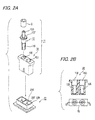
Fig. 2A is an exploded perspective view of avehicle side connector 11 according to an embodiment of the present invention, andFig. 2B illustrates a plan view of aconnector housing 10 illustrated inFig. 2A and a D-D cross-sectional view thereof. -
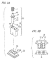
Fig. 3A is an exploded perspective view of acharger side connector 13 according to an embodiment of the present invention, andFig. 3B illustrates a plan view of aconnector housing 10 illustrated inFig. 3A and a D-D cross-sectional view thereof. -
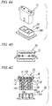
Figs. 4A to 4C are views illustrating the state of both connectors before an in-vehicle electric device side connector according to the present invention is inserted into a battery side connector, in whichFig. 4A is a perspective view of both connectors,Fig. 4B is a plan view thereof, andFig. 4C is an A-A arrow view ofFig. 4B . -
Figs. 5A to 5C are views illustrating the state of both connectors after an in-vehicle electric device side connector according to the present invention is inserted into a battery side connector, in whichFig. 5A is a perspective view of both connectors,Fig. 5B is a plan view thereof, andFig. 5C is an A-A arrow view ofFig. 5B . -
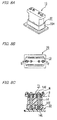
Figs. 6A to 6C are views illustrating the state of both connectors before a charger side connector according to the present invention is inserted into a battery side connector, in whichFig. 6A is a perspective view of both connectors,Fig. 6B is a plan view thereof, andFig. 6C is a B-B arrow view ofFig. 6B . -
Figs. 7A to 7C are views illustrating the state of both connectors which are in the middle of inserting a charger side connector according to the present invention into a battery side connector, in whichFig. 7A is a perspective view of both connectors,Fig. 7B is a plan view thereof, andFig. 7C is a B-B arrow view ofFig. 7B . -
Figs. 8A to 8C are views illustrating the state of both connectors after a charger side connector according to the present invention is inserted into a battery side connector, in whichFig. 8A is a perspective view of both connectors,Fig. 8B is a plan view thereof, andFig. 8C is a B-B arrow view ofFig. 8B . -
Figs. 9A and 9B are views explaining a battery exchange method in the related art, in whichFig. 9A is a conceptual view of the battery exchange method, andFig. 9B is a cross-sectional view illustrating terminal shapes of connectors of respective devices. - Hereinafter, a vehicle side connector that is convertible into a charger side connector according to an embodiment of the present invention will be described on the basis of the drawings.
-
Figs. 2A to 8C are views explaining this embodiment, in whichFigs. 2A to 3B are conceptual views of the whole configuration of the present invention,Figs. 4A to 5C are views explaining a vehicle side connector according to this embodiment, andFigs. 6A to 8C are views explaining a charger side connector. - In
Figs. 2A to 3B , 11 denotes a vehicle side connector, 13 denotes a charger side connector, and 20 denotes a battery side connector. Hereinafter, explanation will be made in the order of thevehicle side connector 11, thecharger side connector 13, and thebattery side connector 20. - In
Figs. 2A and 2B , thevehicle side connector 11 includes aconnector housing 10 having two insertion holes, a vehicleside connector terminal 12 inserted into the two insertion holes of theconnector housing 10, and a spacer S inserted into awire connection portion 12C, which has a cylindrical part on which a head part of the vehicleside connector terminal 12 is formed, to be in contact with aflange portion 12F. Thevehicle side connector 11 is covered by a rear holder H (seeFig. 4C ) and is fastened by a screw N (seeFig. 4C ). - The vehicle
side connector terminal 12 is in the form of a lengthwise metal cylinder as a whole, and theflange portion 12F is formed on a slightly upper portion of the center thereof. Thewire connection portion 12C above theflange portion 12F is used as a wire crimping portion. Theterminal connection portion 12S, which has a cylindrical part that is ahollow portion 12V formed below theflange portion 12F, has a slit formed from the lower front end to the middle of theterminal connection portion 12S to form an elastic portion, and thus abattery side terminal 20T of thebattery side connector 20 can be easily inserted into the insertion hole. - In the
connector housing 10, a wire connectionportion accommodation portion 10C, which is formed in a cylindrical space that extends from theflange portion 12F to the outside with a diameter width of theflange portion 12F, and a terminal connectionportion accommodation portion 10S, which is formed in a cylindrical space that extends from the wire connectionportion accommodation portion 10C to a counterpart terminal insertion hole with a diameter that is smaller than the diameter width of the wire connectionportion accommodation portion 10C, are provided. - The rear holder H blocks the wire connection
portion accommodation portion 10C of theconnector housing 10. On the rear holder H, a through-hole H1, into which thewire connection portion 12C of the vehicleside connector terminal 12 is penetratingly inserted, is formed, and by penetratingly inserting theconnection portion 12C of the vehicleside connector terminal 12 into the through-hole H1, the leaning of the vehicleside connector terminal 12 is suppressed. - In the case of using a commonly used connector housing (hereinafter referred to as a "common housing") on the vehicle side, the
vehicle side connector 11 is incorporated in a cylindrical space (accommodation space) that extends from theflange portion 12F in which the wire crimping portion of the terminal is accommodated to the rear holder H in a state where the spacer S is assembled on the vehicleside connector terminal 12. Through this, the vehicleside connector terminal 12 is fixed by the spacer S, and thus the vehicleside connector terminal 12 can be fitted onto the batteryside connector terminal 20T when it is inserted into the connector. - In
Figs. 3A and 3B , thecharger side connector 13 includes aconnector housing 10 having two insertion holes, a chargerside connector terminal 14 inserted into the two insertion holes of theconnector housing 10, and a spring C inserted into awire connection portion 14C of the chargerside connector terminal 14 to be in contact with aflange portion 14F. Thecharger side connector 14 is covered by a rear holder H (seeFig. 5C ) and is fastened by a screw N (seeFig. 5C ). - The charger
side connector terminal 14 is in the form of a lengthwise metal cylinder as a whole, and theflange portion 14F is formed on a slightly upper portion of the center thereof. Thewire connection portion 14C above the flange portion F is used as a wire crimping portion. Theterminal connection portion 14S below theflange portion 14F has a slightly large diameter, and is solid. Aconcave portion 14K (seeFig. 6C ) is formed at the lower front end, and the front end of the batteryside connector terminal 20T of thebattery side connector 20 becomes in contact with theconcave portion 14K. - In the
connector housing 10, a wire connectionportion accommodation portion 10C, which is formed in a cylindrical space that extends from the flange portion F to the outside with a diameter width of theflange portion 14F, and a terminal connectionportion accommodation portion 10S, which is formed in a cylindrical space that extends from the wire connectionportion accommodation portion 10C to a counterpart terminal insertion hole with a diameter that is smaller than the diameter width of the wire connectionportion accommodation portion 10C, are provided. - On the rear holder H, a through-hole H1, into which the
wire connection portion 14C of the chargerside connector terminal 14 is penetratingly inserted, is formed, and by penetratingly inserting theconnection portion 14C of the chargerside connector terminal 14 into the through-hole H1, the leaning of the chargerside connector terminal 14 is suppressed. - In the case of using a common housing on the charger side, the common housing is incorporated in the
charger side connector 13, in a state that the spring C is assembled on the chargerside connector terminal 14 in a cylindrical space (accommodation space) of the housing where thewire connection portion 14C of the terminal is accommodated. Through this, the chargerside connector terminal 14 is pressed in the direction of the batteryside connector terminal 20T by the spring C, and thus the chargerside connector terminal 14 can be fitted onto the batteryside connector terminal 20T when it is inserted into the connector. - As described, according to this embodiment, the
connector housing 10 of thecharger side connector 13 has the same shape/dimensions/materials as theconnector housing 10 of thevehicle side connector 11, and thus the communization of the components can be sought. - The
battery side connector 20 is the same as that in the related art as illustrated inFigs. 9A and 9B . Anopening 20K, into which the front end of theconnector housing 10 of the counterpart connector is inserted, is formed at two places of theconnector housing 20H, and the batteryside connector terminal 20T is provided in the center of theopenings 20K. - In
Figs. 4A to 5C , in the case of inserting thebattery side connector 20 into thevehicle side connector 11, thevehicle side connector 11 is brought down from right above thebattery side connector 20 toward thebattery side connector 20, and the batteryside connector terminal 20T of thebattery side connector 20 is inserted while rubbing theterminal connection portion 12S (seeFig. 2A ) that is the elastic part of the vehicleside connector terminal 12 of thevehicle side connector 11. At this time, although the vehicleside connector terminal 12 of thevehicle side connector 11 is pushed upward, theflange portion 12F (seeFig. 2A ) becomes in contact with the rear holder H through the spacer S, and thus the vehicleside connector terminal 12 does not move upward. Accordingly, the batteryside connector terminal 20T of thebattery side connector 20 is inserted and fitted into the vehicleside connector terminal 12 to complete the insertion. - In
Figs. 6A to 8C , in the case of inserting thebattery side connector 20 into thecharger side connector 13, thecharger side connector 13 is brought down from right above thebattery side connector 20 toward thebattery side connector 20, and the front end of the batteryside connector terminal 20T of thebattery side connector 20 becomes in contact with and is inserted into theconcave portion 14K formed at the front end of theterminal connection portion 14S (seeFig. 3A ) of the chargerside connector terminal 14 of thecharger side connector 13 while pressing theconcave portion 14K. At this time, although the chargerside connector terminal 14 of thecharger side connector 13 is pushed upward, theflange portion 14F is pushed toward the batteryside connector terminal 20T by the spring C, and the front end of the batteryside connector terminal 20T of thebattery side connector 20 is inserted into and becomes in contact with theconcave portion 14K of the chargerside connector terminal 14 of thecharger side connector 13 to complete the insertion.
Since the charger side is not affected by vibration and dust during traveling of the vehicle, it is not necessary to make the terminal a plug type, and it is sufficient if the front end of the batteryside connector terminal 20T is inserted into and becomes in contact with theconcave portion 14K of the chargerside connector terminal 14. Accordingly, since the opportunity when the terminals rub when the battery is installed in the vehicle or when the battery is removed from the vehicle is reduced to half, the state of the terminal surface is kept well for a long time that is double the time in the related art, and thus contacts may come off or dust may get in the contact type connector, and thus poor contact is hard to happen. - Here, as the related technique, it has been considered that the vehicle side connector being carried adopts the plug type to secure the certain contact between the terminals, and the charger side connector that is put outside the vehicle adopts the contact type connector with a little rubbing.
- According to the battery exchange method of the related technique, as illustrated in
Fig. 1 A , when a battery B1 for vehicle installation that is installed in a vehicle A comes to have been discharged, the battery B1 for vehicle installation that has been discharged is taken out from the vehicle A, and another battery B2 for vehicle installation which has already been charged is loaded on the vehicle A. Accordingly, the charge time can be reduced, and thus the stoppage time can be greatly reduced. According to the work of the meantime, the batteryside connector terminal 20T of theconnector 20 of the battery B1 for vehicle installation that has been discharged is taken off from thehollow part 12V of the vehicleside connector terminal 12 that is the female terminal of thevehicle side connector 11, and then is put "in contact with" theconcave portion 14K of the chargerside connector terminal 14 of thecharger type connector 13 outside the vehicle. - According to this related technique, unlike the related art of
Figs. 9A and 9B , it is assumed that the vehicleside connector terminal 12 of thevehicle side connector 11 and the chargerside connector terminal 14 of thecharger side connector 13 are separated from each other. That is, the vehicleside connector terminal 12 of thevehicle side connector 11 is of a plug type same as thefemale terminal 100T of the connector 100 (seeFig. 9B ) in the related art, and has a terminal lock structure such as a typical lock structure so that thefemale terminal 100T does not retreat during the insertion operation thereof. InFig. 1B , a stepped portion is provided on the boundary between thewire connection portion 12C of the vehicleside connector terminal 12 and theterminal connection portion 12S, and this stepped portion is locked with a stepped portion formed on the inner wall of theconnector housing 10 to make the retreatment thereof impossible. Through this, the chargerside connector terminal 14 of thecharger side connector 13 applies a regular force to the counterpart terminal side since the spring C is inserted into the circumference of thewire connection portion 14C to be accommodated in thehousing 10, and one end of the spring C becomes in contact with the inner wall of the housing. Further, the lower part of the chargerside connector terminal 14 forms theconcave portion 14K at the front end of theterminal connection portion 14S formed on the cylindrical portion, and theconcave portion 14K is shaped as if the front end portion of the batteryside connector terminal 20T of thebattery side connector 20 becomes in contact with theconcave portion 14K. Further, if theconcave portion 14K of theterminal connection portion 14S is pressed by the front portion of the batteryside connector terminal 20T of thebattery side connector 20 during the insertion operation thereof, the chargerside connector terminal 14 comes to retreat. - In
Fig. 1B , if the batteryside connector terminal 20T of the battery B1 for vehicle installation that has been discharged is taken off from thehollow part 12V of the vehicleside connector terminal 12 of thevehicle side connector 11 on the side of the in-vehicleelectric devices 50 and then is pushed toward theconcave portion 14K of the chargerside connector terminal 14 of thecharger side connector 13 outside the vehicle, the chargeside connector terminal 14 is pushed by the batteryside connector terminal 20T into the inside of thecharger side connector 13 to be urged by the spring C, the batteryside connector terminal 20T of thebattery side connector 20 becomes in contact with theconcave portion 14K of the chargerside connector terminal 14 of thecharger side connector 13 in a state where the both housings are completely fitted into each other to start the charging. - As described above, since the front end of the battery
side connector terminal 20T of thebattery side connector 20 is in a simple contact state with theconcave portion 14K of the chargerside connector terminal 14 through pressing thereof, but is not of the plug type in the related art that the terminals strongly rub each other, promotion of abrasion of the connector terminal and abrasion of the terminal surface treatment can be avoided, and the lifespan of the terminal is prolonged for double soon in comparison to that in the related art. - Further, since the battery is outside of the vehicle during charging by this contact type, no vibration occurs, and there is not the fear that dust invades the contact portion since the charge environment is regulated well.
- In the related technique as described above, the plug connector is used as the vehicle side connector in order to secure certain contact between the terminals, and the contact type connector with a little rubbing is used as the charger side connector. Here, according to the vehicle side connector that is the plug type connector, there is the need that the plug type terminal is locked in and fixed to the inside of the connector housing, and thus the vehicle side connector that is completed by locking and fixing the terminal is unable to be converted into the charger side connector in which the spring is provided to move the terminal. Accordingly, it is necessary to separately make a connector with a terminal locking structure.
- As described above, according to an embodiment of the present invention, by diverting the technique in the related art and securing reliability and by changing the combination to match the use terms, the use terms of the battery can be extended. Specifically, by dividedly using the charger side and vehicle side terminal shapes based on the user terms, the abrasion of the battery side terminal is suppressed, and the battery can be used for a long term to reduce the cost to hang to the battery.
- Priority is claimed on Japanese Patent Application No.
2011-048330 - According to the connector of the present invention, which can be assembled in the vehicle and be connected to the battery for vehicle installation, the connector housing in the connector that feeds the in-vehicle electric devices can be commonized through only the change of the inside design thereof, resulting in saving the cost.
-
- 10: connector housing (common)
- 10C: wire connection portion accommodation portion
- 10S: terminal connection portion accommodation portion
- 11: vehicle side connector (connector)
- 12: vehicle side connector terminal (connector terminal)
- 12C: wire connection portion
- 12F: flange portion
- 12S: terminal connection portion
- 12V: hollow portion
- 13: charger side connector (connector)
- 14: charger side connector terminal (connector terminal)
- 14C: wire connection portion
- 14F: flange portion
- 14K: concave portion
- 14S: terminal connection portion
- 20: battery side connector
- 20K: opening
- 20T: battery side connector terminal (male)
- AC: alternate current power supply
- 50: in-vehicle electric device
- B1: completely discharged battery for vehicle installation
- B2: fully charged battery for vehicle installation
- C: spring
- H: rear holder
- H1: through-hole
- N: screw
- S: spacer
Claims (1)
- A connector including a connector housing and a connector terminal accommodated in the connector housing to be connected to a battery for vehicle installation,
wherein the connector terminal has one end at which a terminal connection portion, which is connected to a battery side connector terminal that is installed in the connector housing of the battery for vehicle installation, is installed, and the other end at which a wire connection portion, which is connected to a wire that is drawn from the rear side of the connector housing, is installed, wherein a flange portion that extends outwardly of the connector terminal is installed between the terminal connection portion and the wire connection portion,
wherein the connector housing includes a wire connection portion accommodation portion which is successively formed in an opening into which the connector terminal is inserted from the rear side, has a diameter that is substantially equal to a diameter of the flange portion, and is adapted to accommodate the wire connection portion, and a terminal connection portion accommodation potion which is installed forward than the wire connection portion accommodation portion, has a diameter that is smaller than a diameter of the wire connection portion, and is adapted to accommodate the terminal connection portion, and
wherein a rear holder, in which a through-hole into which a part of the wire connection portion is adapted to be penetratingly inserted is formed, is installed to cover the opening of the connector housing, and the part of the wire connection portion is penetratingly inserted into the through-hole of the rear holder to form an accommodation space in which a pipe-shaped spacer or a spring, into which the wire connection portion is penetratingly inserted, is adapted to be disposed.
Applications Claiming Priority (2)
| Application Number | Priority Date | Filing Date | Title |
|---|---|---|---|
| JP2011048330A JP5711574B2 (en) | 2011-03-04 | 2011-03-04 | connector |
| PCT/JP2012/054945 WO2012121061A1 (en) | 2011-03-04 | 2012-02-28 | Connector |
Publications (3)
| Publication Number | Publication Date |
|---|---|
| EP2683038A1 true EP2683038A1 (en) | 2014-01-08 |
| EP2683038A4 EP2683038A4 (en) | 2014-07-30 |
| EP2683038B1 EP2683038B1 (en) | 2019-05-15 |
Family
ID=46798029
Family Applications (1)
| Application Number | Title | Priority Date | Filing Date |
|---|---|---|---|
| EP12754724.8A Active EP2683038B1 (en) | 2011-03-04 | 2012-02-28 | Connector |
Country Status (5)
| Country | Link |
|---|---|
| US (1) | US8851937B2 (en) |
| EP (1) | EP2683038B1 (en) |
| JP (1) | JP5711574B2 (en) |
| CN (1) | CN103329362B (en) |
| WO (1) | WO2012121061A1 (en) |
Cited By (1)
| Publication number | Priority date | Publication date | Assignee | Title |
|---|---|---|---|---|
| WO2015124245A1 (en) * | 2014-02-20 | 2015-08-27 | Rosenberger Hochfrequenztechnik Gmbh & Co. Kg | Plug connection |
Families Citing this family (18)
| Publication number | Priority date | Publication date | Assignee | Title |
|---|---|---|---|---|
| US9077098B2 (en) * | 2012-06-14 | 2015-07-07 | Magna Electronics Inc. | Electrical connector with sealed pins |
| JP5539454B2 (en) * | 2012-07-20 | 2014-07-02 | ファナック株式会社 | Striated structure for industrial robot with hollow member |
| JP6182432B2 (en) * | 2013-11-11 | 2017-08-16 | 矢崎総業株式会社 | Wire holder |
| JP6122094B1 (en) * | 2015-12-25 | 2017-04-26 | 株式会社フジクラ | Method for manufacturing charging connector assembly |
| CN105449414A (en) * | 2015-12-29 | 2016-03-30 | 中物功能材料研究院有限公司 | Scalable contact conductive connection device |
| US10106047B2 (en) * | 2016-02-12 | 2018-10-23 | Radio Flyer Inc. | Electronic controls for battery-powered ride-on vehicle |
| JP6551300B2 (en) * | 2016-05-19 | 2019-07-31 | 住友電装株式会社 | connector |
| JP6467383B2 (en) * | 2016-08-10 | 2019-02-13 | 矢崎総業株式会社 | connector |
| DE102017100538B3 (en) * | 2017-01-12 | 2018-05-09 | Knorr-Bremse Systeme für Nutzfahrzeuge GmbH | Electrical connector of a plug and a mating connector and electrical or electro-pneumatic braking device of a vehicle |
| CN107069283A (en) * | 2017-06-14 | 2017-08-18 | 四川普诺顿斯电子科技有限公司 | A kind of car body electric connector |
| CN107123879B (en) * | 2017-06-21 | 2023-04-28 | 小熊电器股份有限公司 | Switch joint with reliable connection and cooker |
| WO2019089438A1 (en) * | 2017-10-31 | 2019-05-09 | Molex, Llc | Connector |
| JP6960881B2 (en) * | 2017-10-31 | 2021-11-05 | モレックス エルエルシー | connector |
| US11465663B2 (en) * | 2019-05-20 | 2022-10-11 | Lg Electronics Inc. | Cart robot having charge function |
| US11289774B2 (en) * | 2019-06-25 | 2022-03-29 | Kokam Co., Ltd. | Connector and battery module including the same |
| DE102019213450B3 (en) * | 2019-09-04 | 2021-01-14 | Volkswagen Aktiengesellschaft | Battery module and electrically powered motor vehicle |
| KR102307654B1 (en) * | 2020-05-28 | 2021-10-05 | 한국전력공사 | Connector terminal for electric vehicle |
| CN114944577A (en) * | 2022-06-21 | 2022-08-26 | 大连日牵电机有限公司 | Locking type power connector adaptive to electric wheel lead-out cable |
Family Cites Families (12)
| Publication number | Priority date | Publication date | Assignee | Title |
|---|---|---|---|---|
| US3718881A (en) * | 1972-03-27 | 1973-02-27 | Gen Motors Corp | Detachable fastening clip |
| ZA785334B (en) * | 1977-09-22 | 1979-09-26 | J Wishart | Improved split cycle internal combustion engines |
| JPH0515073A (en) | 1991-06-28 | 1993-01-22 | Shinko Electric Co Ltd | Power supply device for automatic charging of an automated guided vehicle battery |
| DE4229687A1 (en) * | 1992-09-05 | 1994-03-10 | Dieter Kitto Werkzeug Und Masc | Battery exchange station for electrically driven road vehicle - enables discharged batteries to be replaced without waiting by charged batteries and functions automatically |
| ATE233964T1 (en) | 1994-06-29 | 2003-03-15 | Vorwerk Co Interholding | ELECTRICAL CONNECTION |
| JP3750907B2 (en) | 1999-11-16 | 2006-03-01 | 矢崎総業株式会社 | Connector waterproof structure |
| DE10332325A1 (en) * | 2003-07-16 | 2005-02-03 | Schaltbau Gmbh | Loaded contact connector |
| JP5044508B2 (en) * | 2008-08-26 | 2012-10-10 | 矢崎総業株式会社 | connector |
| JP5310248B2 (en) * | 2009-05-13 | 2013-10-09 | 住友電装株式会社 | connector |
| ES2565479T3 (en) * | 2009-10-26 | 2016-04-05 | Heyco, Inc. | Electrical connectors for photovoltaic installations |
| US8545276B2 (en) * | 2011-11-03 | 2013-10-01 | Fereidoun A. Farahani | Multi-pin breakaway connector with fixed and retractable pins |
| US8708745B2 (en) * | 2011-11-07 | 2014-04-29 | Apple Inc. | Dual orientation electronic connector |
-
2011
- 2011-03-04 JP JP2011048330A patent/JP5711574B2/en not_active Expired - Fee Related
-
2012
- 2012-02-28 US US13/817,846 patent/US8851937B2/en active Active
- 2012-02-28 WO PCT/JP2012/054945 patent/WO2012121061A1/en not_active Ceased
- 2012-02-28 EP EP12754724.8A patent/EP2683038B1/en active Active
- 2012-02-28 CN CN201280006452.XA patent/CN103329362B/en not_active Expired - Fee Related
Cited By (2)
| Publication number | Priority date | Publication date | Assignee | Title |
|---|---|---|---|---|
| WO2015124245A1 (en) * | 2014-02-20 | 2015-08-27 | Rosenberger Hochfrequenztechnik Gmbh & Co. Kg | Plug connection |
| US9865954B2 (en) | 2014-02-20 | 2018-01-09 | Rosenberger Hochfrequenztechnik Gmbh & Co. Kg | Plug connection |
Also Published As
| Publication number | Publication date |
|---|---|
| US20130149918A1 (en) | 2013-06-13 |
| EP2683038A4 (en) | 2014-07-30 |
| CN103329362B (en) | 2015-12-09 |
| WO2012121061A1 (en) | 2012-09-13 |
| JP2012186017A (en) | 2012-09-27 |
| CN103329362A (en) | 2013-09-25 |
| US8851937B2 (en) | 2014-10-07 |
| JP5711574B2 (en) | 2015-05-07 |
| EP2683038B1 (en) | 2019-05-15 |
Similar Documents
| Publication | Publication Date | Title |
|---|---|---|
| EP2683038B1 (en) | Connector | |
| US9761983B2 (en) | Connector assembly and terminal retainer | |
| CN108631090B (en) | car charging plug-in connector | |
| US9484682B2 (en) | USB socket | |
| CN103718387B (en) | Adapter | |
| US8858264B2 (en) | Electrical terminal retainer and receptacle assembly | |
| US9028272B2 (en) | Foreign material removing structure for charger | |
| US20190267758A1 (en) | Electricity charging plug device, electricity charging connection device, electricity charging device and electric vehicle | |
| JP2019515428A (en) | Output contact with exchangeable contact area | |
| US20220324342A1 (en) | Electro mechanical or electrical connector for use in electric vehicle | |
| KR20130019200A (en) | Interface apparatus for charged up battery of electromobile | |
| CN102856689A (en) | Connector | |
| CN109565127B (en) | An electric plug-in device and electric vehicle | |
| KR102647877B1 (en) | Plug device for charging electricity | |
| CN101409407B (en) | Device for electric connection between a portable receiver and a power source | |
| CN203850894U (en) | Vehicular charger | |
| CN107571766B (en) | A new energy vehicle charging auxiliary fixing device | |
| US11588275B2 (en) | Electrical interface assembly | |
| KR102481777B1 (en) | Charge Inlet Cap | |
| KR200142569Y1 (en) | Battery terminals and connectors | |
| CN207038774U (en) | A kind of electrical plug-in connection and electric automobile | |
| KR19990052096A (en) | Charging Connector Fastening Structure for Electric Vehicle | |
| JP2001326014A (en) | Hybrid connector structure | |
| WO2006104378A1 (en) | Holder assembly for an apparatus that can be electrically charged via a socket | |
| KR20100112714A (en) | Wiring harness connector |
Legal Events
| Date | Code | Title | Description |
|---|---|---|---|
| PUAI | Public reference made under article 153(3) epc to a published international application that has entered the european phase |
Free format text: ORIGINAL CODE: 0009012 |
|
| 17P | Request for examination filed |
Effective date: 20130215 |
|
| AK | Designated contracting states |
Kind code of ref document: A1 Designated state(s): AL AT BE BG CH CY CZ DE DK EE ES FI FR GB GR HR HU IE IS IT LI LT LU LV MC MK MT NL NO PL PT RO RS SE SI SK SM TR |
|
| DAX | Request for extension of the european patent (deleted) | ||
| A4 | Supplementary search report drawn up and despatched |
Effective date: 20140702 |
|
| RIC1 | Information provided on ipc code assigned before grant |
Ipc: H01R 13/11 20060101ALN20140626BHEP Ipc: H01R 13/24 20060101ALI20140626BHEP Ipc: H01R 13/42 20060101AFI20140626BHEP Ipc: H01R 13/52 20060101ALI20140626BHEP |
|
| STAA | Information on the status of an ep patent application or granted ep patent |
Free format text: STATUS: EXAMINATION IS IN PROGRESS |
|
| 17Q | First examination report despatched |
Effective date: 20170215 |
|
| REG | Reference to a national code |
Ref country code: DE Ref legal event code: R079 Ref document number: 602012060150 Country of ref document: DE Free format text: PREVIOUS MAIN CLASS: H01R0013420000 Ipc: H01R0013426000 |
|
| RIC1 | Information provided on ipc code assigned before grant |
Ipc: H01R 13/52 20060101ALI20181217BHEP Ipc: H01R 13/42 20060101AFI20181217BHEP Ipc: H01R 13/11 20060101ALN20181217BHEP Ipc: H01R 13/24 20060101ALI20181217BHEP |
|
| GRAP | Despatch of communication of intention to grant a patent |
Free format text: ORIGINAL CODE: EPIDOSNIGR1 |
|
| STAA | Information on the status of an ep patent application or granted ep patent |
Free format text: STATUS: GRANT OF PATENT IS INTENDED |
|
| RIC1 | Information provided on ipc code assigned before grant |
Ipc: H01R 13/426 20060101AFI20190107BHEP Ipc: H01R 13/14 20060101ALI20190107BHEP Ipc: H01R 13/24 20060101ALN20190107BHEP |
|
| INTG | Intention to grant announced |
Effective date: 20190128 |
|
| GRAS | Grant fee paid |
Free format text: ORIGINAL CODE: EPIDOSNIGR3 |
|
| GRAA | (expected) grant |
Free format text: ORIGINAL CODE: 0009210 |
|
| STAA | Information on the status of an ep patent application or granted ep patent |
Free format text: STATUS: THE PATENT HAS BEEN GRANTED |
|
| AK | Designated contracting states |
Kind code of ref document: B1 Designated state(s): AL AT BE BG CH CY CZ DE DK EE ES FI FR GB GR HR HU IE IS IT LI LT LU LV MC MK MT NL NO PL PT RO RS SE SI SK SM TR |
|
| REG | Reference to a national code |
Ref country code: CH Ref legal event code: EP Ref country code: GB Ref legal event code: FG4D |
|
| REG | Reference to a national code |
Ref country code: DE Ref legal event code: R096 Ref document number: 602012060150 Country of ref document: DE |
|
| REG | Reference to a national code |
Ref country code: IE Ref legal event code: FG4D |
|
| REG | Reference to a national code |
Ref country code: NL Ref legal event code: MP Effective date: 20190515 |
|
| REG | Reference to a national code |
Ref country code: LT Ref legal event code: MG4D |
|
| PG25 | Lapsed in a contracting state [announced via postgrant information from national office to epo] |
Ref country code: PT Free format text: LAPSE BECAUSE OF FAILURE TO SUBMIT A TRANSLATION OF THE DESCRIPTION OR TO PAY THE FEE WITHIN THE PRESCRIBED TIME-LIMIT Effective date: 20190915 Ref country code: AL Free format text: LAPSE BECAUSE OF FAILURE TO SUBMIT A TRANSLATION OF THE DESCRIPTION OR TO PAY THE FEE WITHIN THE PRESCRIBED TIME-LIMIT Effective date: 20190515 Ref country code: FI Free format text: LAPSE BECAUSE OF FAILURE TO SUBMIT A TRANSLATION OF THE DESCRIPTION OR TO PAY THE FEE WITHIN THE PRESCRIBED TIME-LIMIT Effective date: 20190515 Ref country code: HR Free format text: LAPSE BECAUSE OF FAILURE TO SUBMIT A TRANSLATION OF THE DESCRIPTION OR TO PAY THE FEE WITHIN THE PRESCRIBED TIME-LIMIT Effective date: 20190515 Ref country code: LT Free format text: LAPSE BECAUSE OF FAILURE TO SUBMIT A TRANSLATION OF THE DESCRIPTION OR TO PAY THE FEE WITHIN THE PRESCRIBED TIME-LIMIT Effective date: 20190515 Ref country code: SE Free format text: LAPSE BECAUSE OF FAILURE TO SUBMIT A TRANSLATION OF THE DESCRIPTION OR TO PAY THE FEE WITHIN THE PRESCRIBED TIME-LIMIT Effective date: 20190515 Ref country code: NL Free format text: LAPSE BECAUSE OF FAILURE TO SUBMIT A TRANSLATION OF THE DESCRIPTION OR TO PAY THE FEE WITHIN THE PRESCRIBED TIME-LIMIT Effective date: 20190515 Ref country code: NO Free format text: LAPSE BECAUSE OF FAILURE TO SUBMIT A TRANSLATION OF THE DESCRIPTION OR TO PAY THE FEE WITHIN THE PRESCRIBED TIME-LIMIT Effective date: 20190815 Ref country code: ES Free format text: LAPSE BECAUSE OF FAILURE TO SUBMIT A TRANSLATION OF THE DESCRIPTION OR TO PAY THE FEE WITHIN THE PRESCRIBED TIME-LIMIT Effective date: 20190515 |
|
| PG25 | Lapsed in a contracting state [announced via postgrant information from national office to epo] |
Ref country code: LV Free format text: LAPSE BECAUSE OF FAILURE TO SUBMIT A TRANSLATION OF THE DESCRIPTION OR TO PAY THE FEE WITHIN THE PRESCRIBED TIME-LIMIT Effective date: 20190515 Ref country code: BG Free format text: LAPSE BECAUSE OF FAILURE TO SUBMIT A TRANSLATION OF THE DESCRIPTION OR TO PAY THE FEE WITHIN THE PRESCRIBED TIME-LIMIT Effective date: 20190815 Ref country code: GR Free format text: LAPSE BECAUSE OF FAILURE TO SUBMIT A TRANSLATION OF THE DESCRIPTION OR TO PAY THE FEE WITHIN THE PRESCRIBED TIME-LIMIT Effective date: 20190816 Ref country code: RS Free format text: LAPSE BECAUSE OF FAILURE TO SUBMIT A TRANSLATION OF THE DESCRIPTION OR TO PAY THE FEE WITHIN THE PRESCRIBED TIME-LIMIT Effective date: 20190515 |
|
| REG | Reference to a national code |
Ref country code: AT Ref legal event code: MK05 Ref document number: 1134520 Country of ref document: AT Kind code of ref document: T Effective date: 20190515 |
|
| PG25 | Lapsed in a contracting state [announced via postgrant information from national office to epo] |
Ref country code: RO Free format text: LAPSE BECAUSE OF FAILURE TO SUBMIT A TRANSLATION OF THE DESCRIPTION OR TO PAY THE FEE WITHIN THE PRESCRIBED TIME-LIMIT Effective date: 20190515 Ref country code: AT Free format text: LAPSE BECAUSE OF FAILURE TO SUBMIT A TRANSLATION OF THE DESCRIPTION OR TO PAY THE FEE WITHIN THE PRESCRIBED TIME-LIMIT Effective date: 20190515 Ref country code: CZ Free format text: LAPSE BECAUSE OF FAILURE TO SUBMIT A TRANSLATION OF THE DESCRIPTION OR TO PAY THE FEE WITHIN THE PRESCRIBED TIME-LIMIT Effective date: 20190515 Ref country code: EE Free format text: LAPSE BECAUSE OF FAILURE TO SUBMIT A TRANSLATION OF THE DESCRIPTION OR TO PAY THE FEE WITHIN THE PRESCRIBED TIME-LIMIT Effective date: 20190515 Ref country code: DK Free format text: LAPSE BECAUSE OF FAILURE TO SUBMIT A TRANSLATION OF THE DESCRIPTION OR TO PAY THE FEE WITHIN THE PRESCRIBED TIME-LIMIT Effective date: 20190515 Ref country code: SK Free format text: LAPSE BECAUSE OF FAILURE TO SUBMIT A TRANSLATION OF THE DESCRIPTION OR TO PAY THE FEE WITHIN THE PRESCRIBED TIME-LIMIT Effective date: 20190515 |
|
| REG | Reference to a national code |
Ref country code: DE Ref legal event code: R097 Ref document number: 602012060150 Country of ref document: DE |
|
| PG25 | Lapsed in a contracting state [announced via postgrant information from national office to epo] |
Ref country code: SM Free format text: LAPSE BECAUSE OF FAILURE TO SUBMIT A TRANSLATION OF THE DESCRIPTION OR TO PAY THE FEE WITHIN THE PRESCRIBED TIME-LIMIT Effective date: 20190515 Ref country code: IT Free format text: LAPSE BECAUSE OF FAILURE TO SUBMIT A TRANSLATION OF THE DESCRIPTION OR TO PAY THE FEE WITHIN THE PRESCRIBED TIME-LIMIT Effective date: 20190515 |
|
| PLBE | No opposition filed within time limit |
Free format text: ORIGINAL CODE: 0009261 |
|
| STAA | Information on the status of an ep patent application or granted ep patent |
Free format text: STATUS: NO OPPOSITION FILED WITHIN TIME LIMIT |
|
| PG25 | Lapsed in a contracting state [announced via postgrant information from national office to epo] |
Ref country code: TR Free format text: LAPSE BECAUSE OF FAILURE TO SUBMIT A TRANSLATION OF THE DESCRIPTION OR TO PAY THE FEE WITHIN THE PRESCRIBED TIME-LIMIT Effective date: 20190515 |
|
| 26N | No opposition filed |
Effective date: 20200218 |
|
| PG25 | Lapsed in a contracting state [announced via postgrant information from national office to epo] |
Ref country code: PL Free format text: LAPSE BECAUSE OF FAILURE TO SUBMIT A TRANSLATION OF THE DESCRIPTION OR TO PAY THE FEE WITHIN THE PRESCRIBED TIME-LIMIT Effective date: 20190515 |
|
| PG25 | Lapsed in a contracting state [announced via postgrant information from national office to epo] |
Ref country code: SI Free format text: LAPSE BECAUSE OF FAILURE TO SUBMIT A TRANSLATION OF THE DESCRIPTION OR TO PAY THE FEE WITHIN THE PRESCRIBED TIME-LIMIT Effective date: 20190515 |
|
| REG | Reference to a national code |
Ref country code: CH Ref legal event code: PL |
|
| GBPC | Gb: european patent ceased through non-payment of renewal fee |
Effective date: 20200228 |
|
| REG | Reference to a national code |
Ref country code: BE Ref legal event code: MM Effective date: 20200229 |
|
| PG25 | Lapsed in a contracting state [announced via postgrant information from national office to epo] |
Ref country code: LU Free format text: LAPSE BECAUSE OF NON-PAYMENT OF DUE FEES Effective date: 20200228 Ref country code: MC Free format text: LAPSE BECAUSE OF FAILURE TO SUBMIT A TRANSLATION OF THE DESCRIPTION OR TO PAY THE FEE WITHIN THE PRESCRIBED TIME-LIMIT Effective date: 20190515 |
|
| PG25 | Lapsed in a contracting state [announced via postgrant information from national office to epo] |
Ref country code: CH Free format text: LAPSE BECAUSE OF NON-PAYMENT OF DUE FEES Effective date: 20200229 Ref country code: LI Free format text: LAPSE BECAUSE OF NON-PAYMENT OF DUE FEES Effective date: 20200229 |
|
| PG25 | Lapsed in a contracting state [announced via postgrant information from national office to epo] |
Ref country code: GB Free format text: LAPSE BECAUSE OF NON-PAYMENT OF DUE FEES Effective date: 20200228 Ref country code: IE Free format text: LAPSE BECAUSE OF NON-PAYMENT OF DUE FEES Effective date: 20200228 Ref country code: FR Free format text: LAPSE BECAUSE OF NON-PAYMENT OF DUE FEES Effective date: 20200229 |
|
| PG25 | Lapsed in a contracting state [announced via postgrant information from national office to epo] |
Ref country code: BE Free format text: LAPSE BECAUSE OF NON-PAYMENT OF DUE FEES Effective date: 20200229 |
|
| PGFP | Annual fee paid to national office [announced via postgrant information from national office to epo] |
Ref country code: DE Payment date: 20220105 Year of fee payment: 11 |
|
| PG25 | Lapsed in a contracting state [announced via postgrant information from national office to epo] |
Ref country code: MT Free format text: LAPSE BECAUSE OF FAILURE TO SUBMIT A TRANSLATION OF THE DESCRIPTION OR TO PAY THE FEE WITHIN THE PRESCRIBED TIME-LIMIT Effective date: 20190515 Ref country code: CY Free format text: LAPSE BECAUSE OF FAILURE TO SUBMIT A TRANSLATION OF THE DESCRIPTION OR TO PAY THE FEE WITHIN THE PRESCRIBED TIME-LIMIT Effective date: 20190515 |
|
| PG25 | Lapsed in a contracting state [announced via postgrant information from national office to epo] |
Ref country code: MK Free format text: LAPSE BECAUSE OF FAILURE TO SUBMIT A TRANSLATION OF THE DESCRIPTION OR TO PAY THE FEE WITHIN THE PRESCRIBED TIME-LIMIT Effective date: 20190515 Ref country code: IS Free format text: LAPSE BECAUSE OF FAILURE TO SUBMIT A TRANSLATION OF THE DESCRIPTION OR TO PAY THE FEE WITHIN THE PRESCRIBED TIME-LIMIT Effective date: 20190915 |
|
| REG | Reference to a national code |
Ref country code: DE Ref legal event code: R119 Ref document number: 602012060150 Country of ref document: DE |
|
| PG25 | Lapsed in a contracting state [announced via postgrant information from national office to epo] |
Ref country code: DE Free format text: LAPSE BECAUSE OF NON-PAYMENT OF DUE FEES Effective date: 20230901 |