EP2682915A1 - Illumination optical system for imaging device - Google Patents
Illumination optical system for imaging device Download PDFInfo
- Publication number
- EP2682915A1 EP2682915A1 EP11860040.2A EP11860040A EP2682915A1 EP 2682915 A1 EP2682915 A1 EP 2682915A1 EP 11860040 A EP11860040 A EP 11860040A EP 2682915 A1 EP2682915 A1 EP 2682915A1
- Authority
- EP
- European Patent Office
- Prior art keywords
- prism
- optical system
- prism plate
- light
- illumination optical
- Prior art date
- Legal status (The legal status is an assumption and is not a legal conclusion. Google has not performed a legal analysis and makes no representation as to the accuracy of the status listed.)
- Withdrawn
Links
Images





















Classifications
-
- F—MECHANICAL ENGINEERING; LIGHTING; HEATING; WEAPONS; BLASTING
- F21—LIGHTING
- F21V—FUNCTIONAL FEATURES OR DETAILS OF LIGHTING DEVICES OR SYSTEMS THEREOF; STRUCTURAL COMBINATIONS OF LIGHTING DEVICES WITH OTHER ARTICLES, NOT OTHERWISE PROVIDED FOR
- F21V13/00—Producing particular characteristics or distribution of the light emitted by means of a combination of elements specified in two or more of main groups F21V1/00 - F21V11/00
- F21V13/02—Combinations of only two kinds of elements
-
- G—PHYSICS
- G03—PHOTOGRAPHY; CINEMATOGRAPHY; ANALOGOUS TECHNIQUES USING WAVES OTHER THAN OPTICAL WAVES; ELECTROGRAPHY; HOLOGRAPHY
- G03B—APPARATUS OR ARRANGEMENTS FOR TAKING PHOTOGRAPHS OR FOR PROJECTING OR VIEWING THEM; APPARATUS OR ARRANGEMENTS EMPLOYING ANALOGOUS TECHNIQUES USING WAVES OTHER THAN OPTICAL WAVES; ACCESSORIES THEREFOR
- G03B15/00—Special procedures for taking photographs; Apparatus therefor
- G03B15/02—Illuminating scene
- G03B15/03—Combinations of cameras with lighting apparatus; Flash units
-
- G—PHYSICS
- G06—COMPUTING OR CALCULATING; COUNTING
- G06T—IMAGE DATA PROCESSING OR GENERATION, IN GENERAL
- G06T1/00—General purpose image data processing
-
- H—ELECTRICITY
- H04—ELECTRIC COMMUNICATION TECHNIQUE
- H04N—PICTORIAL COMMUNICATION, e.g. TELEVISION
- H04N23/00—Cameras or camera modules comprising electronic image sensors; Control thereof
- H04N23/56—Cameras or camera modules comprising electronic image sensors; Control thereof provided with illuminating means
Definitions
- the inventions discussed herein are related to an illumination optical system for an image pickup apparatus.
- Image pickup apparatuses designed to read information from a subject such as palm-vein authentication apparatuses and barcode readers (hereinafter simply referred to as "image pickup apparatuses), are known kinds of image pickup apparatuses.
- An image pickup apparatus includes, for example, an illumination optical system 101 and an image pickup optical system 103, as illustrated in FIG. 1 .
- a light source 102 such as an LED, irradiates a subject 106 with irradiation light, and an image sensor 105 provided on the image side of an image pickup lens 104 detects regular reflection light and scattered light which are both incident via the subject 106 (e.g., a palm or a sheet on which a barcode is printed).
- an image pickup apparatus 100 illustrated in FIG. 1 reads information of the subject 106.
- both regular reflection light (solid lines in FIG. 1 ) and scattered light (dashed lines in FIG. 1 ) having a lower light intensity than the regular reflection light are generated from each point on the surface of the subject 106 irradiated with irradiation light, but not all of the regular reflection light rays generated from the points in the field of view of the image pickup optical system 103 enter the image sensor 105.
- point B in FIG. 1 point from which regular reflection light to be detected by the image sensor 105 is emitted
- points A and C in FIG. 1 are illuminated at the same illuminance
- the directivity of illumination light needs to be controlled to appropriately guide light generated from a subject to the image-pickup optical system.
- a technology for controlling the directivity of light a technology is known wherein the direction in which light is emitted is controlled using a prism plate, and such a technology is disclosed by, for example, patent document 1.
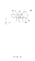
- FIG. 2 , FIG. 3 , FIG. 4 , and FIG. 5 illustrate controlling the direction in which light is emitted by a prism plate in accordance with a prior art.
- FIG. 2 illustrates a relationship between incident light and outgoing light on an XZ cross-section of a prism plate.
- FIG. 3 illustrates a relationship on an XZ cross-section of the prism plate between outgoing light and the light perpendicularly incident onto the prism plate.
- FIG. 4 illustrates a relationship on a YZ cross-section taken on line AA' in FIG. 3 between outgoing light and the light perpendicularly incident onto the prism plate.
- FIG. 5 illustrates a relationship between incident light and outgoing light with the prism plate illustrated in FIG. 2 being viewed from above.
- the XYZ coordinate systems of FIG. 2 to FIG. 5 are right-handed orthogonal coordinate systems provided for the convenience of reference to directions.
- a prism plate 200 illustrated in FIG. 2 includes: a prism surface 201 as an incidence surface on which a plurality of parallel prism columns each having a ridge line 202 are arranged in the X direction; and a plane surface 203 as an outgoing surface.
- the prism plate 200 allows incident light that enters from the prism-surface-201 side to be deflected by refraction at the prism surface 201 and the plane surface 203 so as to control the outgoing direction, with the result that the directivity of the outgoing light can be controlled.
- Patent document 1 Japanese Laid-open Patent Publication No. 2004-171192
- the prism plate 200 illustrated in FIG. 2 cannot emit outgoing light in a Y direction that is parallel to the ridge line 202 (hereinafter referred to as a "ridge-line direction") .
- a ridge-line direction a Y direction that is parallel to the ridge line 202
- the light perpendicularly incident on the prism plate 200 (to be exact, incident light that does not have a Y-direction component; see the solid lines in FIG. 2 ) is deflected only in an X direction that is orthogonal to the ridge line 202.
- the outgoing light is not emitted in the ridge-line direction that is parallel to the ridge line 202.
- incident light that is not incident on the prism plate 200 (to be exact, incident light that has a Y-direction component; see the dashed lines in FIG. 2 ) is deflected by the prism surface 201 in an X direction.
- outgoing light has a Y-direction component in accordance with the Y-direction component of incident light but is not emitted in the ridge-line direction that is parallel to the ridge line 202.
- FIG. 6 illustrates a prism plate that includes an outgoing surface formed as a blasted surface.
- FIG. 7 , FIG. 8 , and FIG. 9 illustrate controlling the direction in which outgoing light is emitted by the prism plate illustrated in FIG. 6 .
- FIG. 7 illustrates a relationship between outgoing light and incident light that enters the prism plate perpendicularly on an XZ cross-section of the prism plate illustrated in FIG. 6 .
- FIG. 8 illustrates a relationship on a YZ cross-section taken on line BB' in FIG.
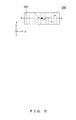
- FIG. 9 illustrates the directivity of outgoing light with the prism plate illustrated in FIG. 6 being viewed from above.
- the XYZ coordinate systems of FIG. 6 to FIG. 9 are right-handed orthogonal coordinate systems provided for the convenience of reference to directions.
- a prism plate 300 illustrated in FIG. 6 includes: a prism surface 301 as an incidence surface on which a plurality of parallel prism columns having a ridge line 302 are arranged in the X direction; and a blasted surface 303 as an outgoing surface.
- incident light deflected in the X direction by the prism surface 301 is diffused by the blasted surface 303, so outgoing light is also emitted in the ridge-line direction that is parallel to the ridge line 302.
- the light incident on the blasted surface 303 has a strong X-direction directivity due to deflection by the prism surface 301.
- the distribution of the amount of outgoing light emitted from the blasted surface 303 in various directions (hereinafter referred to as a "directivity distribution") is shaped like an ellipse having a short axis extending in the ridge-line direction (the Y direction), thereby disadvantageously maintaining a strong X-direction directivity even after diffusion by the blasted surface 303.
- the prism plate 300 having the blasted surface 303 as an outgoing surface can control light directivities only in a limited way, so the light directivities cannot be arbitrarily controlled.
- the application to an illumination optical system of an image pickup apparatus does not allow the directivity of illumination light to be controlled arbitrarily in conformity with the image pickup apparatus.
- an object of the present invention is to provide an illumination optical system for an image pickup apparatus, the illumination optical system being capable of arbitrarily controlling the directivity of illumination light.
- An aspect of the present invention provides an illumination optical system for an image pickup apparatus, the illumination optical system including: a plurality of light sources arranged in a circular loop pattern; and a prism plate shaped like a circular loop, wherein the prism plate includes: a prism surface at which illumination light from the light sources enters and on which a plurality of prism columns arranged in a circular loop pattern in a circumference direction of the prism plate are formed; and an outgoing surface from which the illumination light is emitted, wherein the prism surface includes a flat portion on at least one of a peak formed by each of the plurality of prism columns and a trough formed between the plurality of prism columns, the flat portion being substantially parallel to a tangential direction of the prism plate.
- an illumination optical system for an image pickup apparatus may be provided that is capable of arbitrarily controlling the directivity of illumination light.
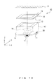
- FIG. 10 illustrates a configuration of an image pickup apparatus in accordance with the present embodiment.
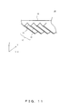
- FIG. 11 is a perspective view of a prism plate included in an illumination optical system illustrated in FIG. 10 in accordance with the present embodiment.
- FIG. 12 is a plan view of the prism plate included in the illumination optical system illustrated in FIG. 10 in accordance with the present embodiment.
- An image pickup apparatus 10 illustrated in FIG. 10 is an image pickup apparatus designed to read information from an object 21, e.g., a palm-vein authentication apparatus or a barcode reader.
- the image pickup apparatus 10 includes: an image-pickup optical system that includes an image-pickup lens 19 and an image sensor 20; and an illumination optical system surrounding the image-pickup optical system.
- the illumination optical system includes: a plurality of LEDs 11 surrounding the image sensor 20 and arranged in a rectangular loop pattern; a prism plate 14 shaped like a rectangular loop; and a light guide 12 located between the plurality of LEDs 11 and the prism plate 14 and shaped like a rectangular tube surrounding the image-pickup lens 19.
- the prism plate 14 includes a prism surface 17 on a side facing the light guide 12, and, on a side facing the object 21, an outgoing surface 18 that is a plane parallel to an XY plane.
- a plurality of prism columns are formed on the prism surface 17 and are arranged in a side direction of the rectangular-loop-shaped prism plate 14.
- the direction in which the prism columns of the rectangular-loop-shaped prism plate 14 are arranged (corresponding to an X direction in FIG. 11 ) will hereinafter be referred to as a "line-up direction"; the direction in which the prism columns extend will hereinafter be referred to as a "ridge-line direction" (corresponding to a Y direction in FIG. 11 ).
- the prism surface 17 includes: inclined portions 15 that correspond to the slopes of a peak formed by each of the plurality of prism columns and that are inclined with respect to the line-up direction; flat portions 16 that correspond to the flat top of the peaks and that are parallel to the line-up direction. That is, when viewed from a cross section orthogonal to the ridge-line direction of the prism columns, each prism column assumes a trapezoidal shape, and the flat portion 16 is provided on each prism column.
- illumination light that is emitted from the LEDs 11 and that enters the light guide 12 advances within the light guide 12 while repeating total reflection, thereby equalizing the directivities of the illumination light, and the illumination light is then emitted from an outgoing surface 13 toward the prism surface 17 of the prism plate 14.
- the prism plate 14 controls the directivity of the illumination light that enters the prism plate 14 from the prism surface 17, and the illumination light is then emitted from the outgoing surface 18 of the prism plate 14. Accordingly, the object 21 is irradiated with illumination light for which a directivity has been controlled.
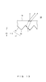
- FIG. 13 illustrates a relationship on a cross section taken on line CC' in FIG. 12 between outgoing light and the light incident onto the prism plate illustrated in FIG. 10 .
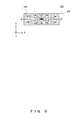
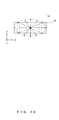
- FIG. 14 illustrates the directivity of outgoing light with the prism plate illustrated in FIG. 10 being viewed from above.
- illumination light that enters at the inclined portion 15 of the prism surface 17 is deflected in the line-up direction (the X direction) due to refraction by the prism surface 17, while illumination light that enters at the flat portion 16 of the prism surface 17 passes through the prism plate 14 without being deflected in the line-up direction due to refraction by the prism surface 17.
- the ratio between a line-up-direction (X-direction) component and a ridge-line-direction (Y-direction) component of the illumination light that enters at the flat portion 16 is maintained since the flat portion 16 and the outgoing surface 18 are parallel to each other.
- the illumination optical system in accordance with the present embodiment allows the directivity of illumination light to be arbitrarily controlled.
- the illumination optical system in accordance with the present embodiment also allows illumination light to be emitted in the ridge-line direction.
- the prism plate 14 may limit the amount of illumination light deflected in the line-up direction. Accordingly, in comparison with illumination optical systems in accordance with the prior art, the illumination optical system in accordance with the present embodiment may limit deflection of the directivity of illumination light in the line-up direction.
- the prism plate 14 allows the amount of illumination light deflected in the line-up direction to be arbitrarily adjusted in accordance with the proportion of an area occupied on the prism surface 17 by the flat portion 16.
- the illumination optical system in accordance with the present embodiment allows the proportion of the amount of illumination light emitted in the line-up direction to the amount of illumination light emitted in the ridge-line direction to be arbitrarily controlled.
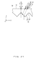
- FIG. 15 illustrates a relationship between outgoing light and the light incident on a prism plate including a flat portion that occupies a higher proportion of a prism surface than the flat portion of the prism plate illustrated in FIG. 10 does.
- FIG. 16 illustrates the directivity of outgoing light with the prism plate illustrated in FIG. 15 being viewed from above.
- the amount of illumination light deflected in the line-up direction may be decreased by increasing the proportion of the area occupied by a flat portion 16a within a prism surface 17a of a prism plate 14a so as to decrease the amount of illumination light incident on an inclined portion 15a.
- a directivity distribution that is closer to a circle is achievable.
- the flat portion 16 of the prism plate 14 is basically parallel to the line-up direction but does not necessarily need to be parallel to the ridge-line direction. Inclining the flat portion 16 with respect to the ridge-line direction allows a balance to be adjusted between the amount of light emitted in a positive ridge-line direction (Y+) and the amount of light emitted in a negative ridge-line direction (Y-). Accordingly, the illumination optical system in accordance with the present embodiment also allows a balance to be arbitrarily controlled between the amount of illumination light emitted in the positive ridge-line direction (Y+) and the amount of illumination light emitted in the negative ridge-line direction (Y-).
- Such an adjustment may be made in accordance with, for example, the distance from the outgoing surface 18 to the object 21.
- the outgoing surface 18 is basically parallel to the line-up direction but does not necessarily need to be parallel to the ridge-line direction. Inclining the outgoing surface 18 with respect to the ridge-line direction may also achieve an advantageous effect similar to the advantageous effect achieved by inclining the flat portion 16 with respect to the ridge-line direction.
- the descriptions above have been given with reference to an exemplary situation in which the directivities of illumination light emitted from the light guide 12 are equalized, but the directivities of illumination light emitted from the light guide 12 do not necessarily need to be equalized.
- the prism plate 14 may arbitrarily control the directivity of emitted light relative to the directivity of incident light. Accordingly, designing the prism plate 14 in accordance with the directivity of illumination light emitted from the light guide 12 allows the illumination optical system in accordance with the present embodiment to arbitrarily control the directivity of illumination light.
- the flat portion 16 and the outgoing surface 18 are desirably parallel to the line-up direction but do not necessarily need to be completely parallel to the line-up direction.
- the flat portion 16 and the outgoing surface 18 may be inclined with respect to the line-up direction, as long as they form a smaller angle of inclination than the inclined portion 15 does and as long as the angle of inclination is within a range such that a function is obtained to distribute a light amount in the ridge-line direction.
- the illumination optical system in accordance with the present embodiment allows a desired directivity to be easily achieved at a low cost.
- a method for determining a designed value of a blast intensity a method may possibly be adopted that uses a trial-manufacture experiment wherein blasting is applied at different blast intensities to materials similar to the material for an actual prism plate, e.g., plastic materials, and then these materials are compared with each other.
- blasting is applied at different blast intensities to materials similar to the material for an actual prism plate, e.g., plastic materials, and then these materials are compared with each other.
- applying blasting to a prism-plate mold at a blast intensity determined using such a method does not lead to an expectation that a prism plate formed by the mold will have a performance similar to the performance of the material used in the trial-manufacture experiment.
- the prism plate 14 does not include a blasted surface. Accordingly, the illumination optical system in accordance with the present embodiment that includes the prism plate 14 allows a desired directivity to be easily achieved at a low cost.
- the prism plate may be designed by designating the shape of the prism plate 14 in accordance with, for example, the width and the angle of the inclined portion 15 and the flat portion 16.
- the design may be represented on a drawing, and, as a result, designed performances may be achieved with a high reproducibility.
- the illumination optical system in accordance with the present embodiment may downsize the entirety of the image pickup apparatus.
- the illumination optical system in accordance with the prior art cannot emit illumination light in the ridge-line direction, so making the illumination optical system loop-shaped to surround an image pickup optical system disables illumination light emitted from a light source from being effectively utilized.
- the illumination optical system in accordance with the present embodiment may emit illumination light in the ridge-line direction so that the directivity of illumination light can be arbitrarily controlled.
- the illumination optical system may be shaped like a rectangular loop in such a manner that the image pickup optical system is located inside the rectangular loop, and hence the illumination optical system in accordance with the present embodiment may downsize the entirety of the image pickup apparatus while maintaining the efficiency for utilization of illumination light.
- FIG. 17 is a perspective view of a variation of the prism plate included in the illumination optical system illustrated in FIG. 10 .
- FIG. 18 illustrates a relationship between outgoing light and the light incident on the prism plate illustrated in FIG. 17 .
- FIG. 19 illustrates a relationship between outgoing light and the light incident on a prism plate including a flat portion that occupies a higher proportion of a prism surface than the flat portion of the prism plate illustrated in FIG. 17 does.
- FIG. 20 illustrates a relationship between outgoing light and the light incident on another variation of the prism plate included in the illumination optical system illustrated in FIG. 10 .
- FIG. 21 illustrates a relationship between outgoing light and the light incident on still another variation of the prism plate included in the illumination optical system illustrated in FIG. 10 .
- a prism plate 22 illustrated in FIG. 17 is different from the prism plate 14 in the sense that a prism surface 25 on a side facing a light guide includes: inclined portions 23 that correspond to the slopes of a peak formed by each of the plurality of prism columns and that are inclined with respect to the line-up direction; and flat portions 24 that correspond to troughs formed between the plurality of prism columns and that are parallel to the line-up direction. That is, when the prism plate 22 is viewed from a cross section orthogonal to the ridge-line direction of the prism columns, each prism column assumes a triangular shape, and the flat portions 24 are provided between the plurality of prism columns.
- the prism plate 22 includes, on a side facing an object, an outgoing surface (an outgoing surface 26) that is a plane parallel to the XY plane.
- illumination light that enters at the inclined portion 23 is deflected in the line-up direction (the X direction) due to refraction by the prism surface 25, while illumination light that enters at the flat portion 24 passes through the prism plate 22 without being deflected in the line-up direction due to refraction by the prism surface 25.
- the prism plate 22 may achieve an advantageous effect similar to the advantageous effect achieved by the prism plate 14.
- the prism plate 22 allows the amount of illumination light deflected in the line-up direction to be arbitrarily adjusted in accordance with the proportion of an area occupied on the prism surface 25 by the flat portion 24.
- the amount of illumination light deflected in the line-up direction may be decreased by increasing the proportion of the area occupied by a flat portion 24a within a prism surface 25a of a prism plate 22a so as to decrease the amount of illumination light incident on an inclined portion 23a.
- a prism plate 27 illustrated in FIG. 20 is different from the prism plate 14 in the sense that the prism plate 27 includes, on a side facing an object, an outgoing surface 31 that is a blasted surface (a diffusing surface) including minute asperities.
- a prism surface (a prism surface 30) formed on a side facing a light guide includes: an inclined portion (an inclined portion 28) inclined with respect to the line-up direction; and a flat portion (a flat portion 29) that is parallel to the line-up direction.
- the prism plate 27 may weaken directivities more greatly than the prism plate 14 does. That is, a directivity distribution is achievable that is closer to a circle than a directivity distribution achieved by the prism plate 14 is. Prism plates such as the prism plate 27 are more advantageous when, for example, the directivity of illumination light emitted from the light guide 12 illustrated in FIG. 10 is deflected significantly.
- a prism plate such as a prism plate 32 illustrated in FIG. 21 , i.e., a prism plate including, on a side facing a light guide, a prism surface 35 including: an inclined portion 33 inclined with respect to the line-up direction; and a flat portion 34 that corresponds to a trough and that is parallel to the line-up direction
- an advantageous effect similar to the advantageous effect achieved by the prism plate 27 is achievable as long as a blasted surface on which minute asperities are formed is provided on the side facing an object.
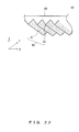
- FIG. 22 is a perspective view of a prism plate included in an illumination optical system in accordance with the present embodiment.
- FIG. 23 illustrates a relationship between outgoing light and the light incident on the prism plate illustrated in FIG. 22 .
- FIG. 24 illustrates a relationship on a cross section taken on line DD' in FIG. 23 between outgoing light and the light incident onto the prism plate illustrated in FIG. 22 .
- FIG. 25 illustrates the directivity of outgoing light with the prism plate illustrated in FIG. 22 being viewed from above. Note that, except for the fact that a prism plate 40 illustrated in FIG. 22 is provided in place of the prism plate 14, the illumination optical system in accordance with the present embodiment is similar to the illumination optical system in accordance with embodiment 1 illustrated in FIG. 10 .
- the prism plate 40 illustrated in FIG. 22 includes: a prism surface 43 which is provided on a side facing a light guide and on which a plurality of prism columns are formed; and an outgoing surface 44 which is provided on a side facing an object and which is a plane parallel to the XY plane.
- the prism surface 43 includes: inclined portions 41 that correspond to the slopes of a peak formed by each of the plurality of prism columns; and ridge lines 42 of the peaks, and each prism column assumes a triangular shape when viewed from a cross section orthogonal to the ridge-line direction of the prism columns.
- the inclined portions 41 are formed as a blasted surface (a diffusing surface) on which minute asperities are formed.
- the prism plate 40 of the illumination optical system causes illumination light that has passed through the inclined portion 41 to be emitted in various directions, including the ridge-line direction, and deflects the center of the distribution of the amount of light (hereinafter referred to as an "optical axis") in the line-up direction.
- the directivity distribution of illumination light emitted from the outgoing surface 44 is shaped like an ellipse, and illumination light is also emitted in the ridge-line direction.
- the blast intensity that is used to form the inclined portion 41 of the prism plate 40 as a blasted surface may be adjusted to adjust the amount of illumination light emitted in the ridge-line direction.
- the illumination optical system in accordance with the present embodiment may arbitrarily control the directivity of illumination light.
- diffusion does not occur after deflection but occurs simultaneously with deflection so that diffusion caused by the blasted surface can be more efficient than in the case of the prism plate 300 illustrated in FIG. 5 .
- the illumination optical system in accordance with the present embodiment may broaden the range of directivity control, thereby achieving a directivity distribution that is closer to a circle.
- FIG. 26 illustrates a relationship between outgoing light and the light incident on a variation of the prism plate included in the illumination optical system in accordance with the present embodiment.
- FIG. 27 illustrates a relationship on a cross section taken on line EE' in FIG. 26 between outgoing light and the light incident onto the prism plate illustrated in FIG. 26 .
- FIG. 28 illustrates the directivity of outgoing light with the prism plate illustrated in FIG. 26 being viewed from above.
- a prism plate 45 illustrated in FIG. 26 and FIG. 27 is different from the prism plate 40 in the sense that the prism plate 45 includes, on a side facing an object, an outgoing surface 46 that is a blasted surface (a diffusing surface) including minute asperities.
- the prism surface 43 includes, on the side facing the light guide, an inclined portion 41 formed as a blasted surface.
- the illumination optical system that includes the prism plate 45 may significantly broaden the range of directivity control, thereby achieving a directivity distribution that is closer to a circle as illustrated in FIG. 28 .
- FIG. 29 illustrates a configuration of an image pickup apparatus in accordance with the present embodiment.
- FIG. 30 is a perspective view of a prism plate included in an illumination optical system illustrated in FIG. 29 .
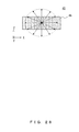
- FIG. 31 is a plan view of the prism plate illustrated in FIG. 30 .
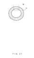
- FIG. 32 is an enlarged plan view of the portion of the prism plate illustrated in FIG. 31 that is indicated by the dashed line.
- An image pickup apparatus 50 illustrated in FIG. 29 is an image pickup apparatus designed to read information from an object 61, e.g., a palm-vein authentication apparatus or a barcode reader.
- the image pickup apparatus 50 includes: an image-pickup optical system that includes an image-pickup lens 59 and an image sensor 60; and an illumination optical system designed for the image pickup apparatus and surrounding the image-pickup optical system.
- the illumination optical system includes: a plurality of LEDs 51 surrounding the image sensor 60 and arranged in a circular loop pattern; a prism plate 54 shaped like a circular loop; and a light guide 52 located between the plurality of LEDs 51 and the prism plate 54 and shaped like a circular tube surrounding the image-pickup lens 59.
- the prism plate 54 includes a prism surface 57 on a side facing the light guide 52, and, on a side facing the object 61, an outgoing surface 58 that is a plane orthogonal to an optical axis of the image pickup optical system. It is noted that the prism plate 54 is the same as the prism plate 14 of embodiment 1 except that it is shaped like a circular loop.
- a plurality of prism columns are formed on the prism surface 57.
- the plurality of prism columns are arranged in a circular loop pattern in the circumference direction of the circular-loop-shaped prism plate 54, and the prism columns are each extended in the radial direction of the circular-loop-shaped prism plate 54.
- the prism surface 57 includes: inclined portions 55 that correspond to the slopes of a peak formed by each of the plurality of prism columns and that are inclined with respect to the tangential direction of the prism plate 54; and flat portions 56 that correspond to the flat top of the peaks and that are parallel to the tangential direction of the prism plate 54. That is, when viewed from a cross section orthogonal to the radial direction of the prism plate 54, each prism column assumes a trapezoidal shape, and the flat portion 56 is provided on each prism column.
- the height of the peaks of the prism columns arranged in a circular loop pattern in the circumference direction is constant over the prism plate 54 (i.e., constant from the outer circumference to the internal circumference); in particular, the height of the peaks is H1 over the entirety of the prism plate 54.
- the intervals between the peaks are also constant; in particular, the intervals are interval W.
- the outer circumference of the circular-loop-shaped prism plate 54 is understandably longer than the internal circumference, and hence, although the width of the inside of each prism column is width P, the width of each prism column becomes longer from the internal circumference of the prism plate 54 to the outer circumference.
- the increment between width P and the width of the prism columns that becomes longer from the internal circumference to the outer circumference is the width of the flat portion 56.
- illumination light that is emitted from the LEDs 51 and enters the light guide 52 advances within the light guide 52 while repeating total reflection, thereby equalizing the directivities of the illumination light, and the illumination light is then emitted from an outgoing surface 53 toward the prism surface 57 of the prism plate 54.
- the prism plate 54 controls the directivity of the illumination light that enters the prism plate 54 from the prism surface 57, and the illumination light is then emitted from the outgoing surface 58 of the prism plate 54. Accordingly, the object 61 is irradiated with illumination light for which a directivity has been controlled.
- illumination light that enters at the inclined portion 55 of the prism surface 57 is deflected in the tangential direction due to refraction by the prism surface 57, while illumination light that enters at the flat portion 56 of the prism surface 57 passes through the prism plate 54 without being deflected in the tangential direction due to refraction by the prism surface 57.
- the ratio between a tangential-direction component and a radial-direction component of the illumination light is maintained since the flat portion 56 and the outgoing surface 58 are parallel to each other.
- the illumination optical system in accordance with the present embodiment allows the directivity of illumination light to be arbitrarily controlled. More particularly, the illumination optical system in accordance with the present embodiment also allows illumination light to be emitted in the radial direction, thereby limiting deflection of the directivity of illumination light in the tangential direction.
- the illumination optical system in accordance with the present embodiment allows the amount of illumination light deflected in the tangential direction to be arbitrarily adjusted in accordance with the proportion of an area occupied on the prism surface 57 by the flat portion 56.
- the illumination optical system in accordance with the present embodiment allows the proportion of the amount of illumination light emitted in the tangential direction to the amount of illumination light emitted in the radial direction to be arbitrarily controlled.
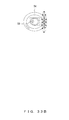
- FIG. 33A illustrates the directivity of emitted light in the absence of a flat portion of the prism surface of the prism plate illustrated in FIG. 30 .
- FIG. 33B illustrates the directivity of emitted light under a condition in which a flat portion occupies a low proportion of a prism surface of the prism plate illustrated in FIG. 30 .
- FIG. 33C illustrates the directivity of emitted light under a condition in which a flat portion occupies an intermediate proportion of the prism surface of the prism plate illustrated in FIG. 30 .
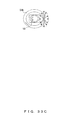
- FIG. 33D illustrates the directivity of emitted light under a condition in which a flat portion occupies a high proportion of the prism surface of the prism plate illustrated in FIG. 30 .
- illumination light is not emitted in the radial direction even when incident light from various directions enters the prism plate 54a, and hence illumination light emitted from the illumination optical system is distributed in a figure eight pattern, with a portion narrowed in the radial direction, as illustrated in FIG. 33A .
- illumination light emitted from the illumination optical system has an ellipse-shaped directivity distribution that indicates a strong tangential-direction directivity in comparison with a radial-direction directivity.
- illumination light emitted from the illumination optical system has a directivity distribution that indicates a strong tangential-direction directivity relative to a radial-direction directivity but has an ellipsoid shape that is relatively close to a circle.
- illumination light emitted from the illumination optical system has a directivity distribution substantially shaped like a cycle.
- FIG. 34 illustrates a relationship between an illuminance evaluation plane and an outgoing surface of an illumination optical system.
- FIG. 35A illustrates an illuminance distribution on an evaluation plane under a condition in which illumination light emitted from an illumination optical system indicates the directivity illustrated in FIG. 33A .
- FIG. 35B illustrates an illuminance distribution on an evaluation plane under a condition in which illumination light emitted from an illumination optical system indicates the directivity illustrated in FIG. 33B .
- FIG. 35C illustrates an illuminance distribution on an evaluation plane under a condition in which illumination light emitted from an illumination optical system indicates the directivity illustrated in FIG. 33C .
- FIG. 35A illustrates an illuminance distribution on an evaluation plane under a condition in which illumination light emitted from an illumination optical system indicates the directivity illustrated in FIG. 33A .
- FIG. 35B illustrates an illuminance distribution on an evaluation plane under a condition in which illumination light emitted from an illumination optical system indicates the directivity illustrated in FIG. 33
- FIG. 35D illustrates an illuminance distribution on an evaluation plane under a condition in which illumination light emitted from an illumination optical system indicates the directivity illustrated in FIG. 33D .
- FIG. 36 illustrates a change in an illuminance distribution that is made on an evaluation plane by a change in the directivity of illumination light emitted from an illumination optical system.
- an optical-axis direction of the image pickup optical system is defined as a z-axis direction
- z coordinates of the outgoing surface 58 of the illumination optical system are defined as 0
- z coordinates of the evaluation plane that correspond to the surface of the object 61 are defined as z1.
- a radial direction that is orthogonal to the optical-axis direction of the image pickup optical system is defined as an r direction
- r coordinates of the optical axis of the image pickup optical system are defined as 0.
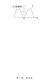
- an illuminance distribution D does not become flat and a central portion of the evaluation plane indicates a high illuminance, as illustrated in FIG. 35D .
- the illumination optical system is shaped like a circular loop.
- illumination light illustrated in FIG. 33C having a directivity distribution shaped like an ellipse that is relatively close to a circle and that has a short axis extending in the radial direction enters the evaluation plane, a substantially planar illumination distribution C is generated on the evaluation plane, as illustrated in FIG. 35C .
- the illumination optical system in accordance with the present embodiment allows the proportion of the area occupied on the prism surface by the flat portion to be changed so as to change the amount of illumination light emitted in the radial direction, so that the directivity distribution of the illumination light can be controlled, with the result that the illumination distribution on the evaluation plane (the object) can be arbitrarily controlled as illustrated in FIG. 36 .
- the flat portion 56 of the prism plate 54 is basically parallel to the tangential direction but does not necessarily need to be parallel to the radial direction. Inclining the flat portion 56 with respect to the radial direction allows a balance to be adjusted between the amount of light emitted in a positive radial direction (a direction from the internal circumference to the outer circumference of the prism plate 54) and the amount of light emitted in a negative radial direction (a direction from the outer circumference to the internal circumference of the prism plate 54). Accordingly, the illumination optical system in accordance with the present embodiment also allows a balance to be arbitrarily controlled between the amount of illumination light emitted in the positive radial direction and the amount of illumination light emitted in the negative radial direction.
- the outgoing surface 58 is basically parallel to the tangential direction but does not necessarily need to be parallel to the radial direction. Inclining the outgoing surface 58 with respect to the radial direction may also achieve an advantageous effect similar to the advantageous effect achieved by inclining the flat portion 56 with respect to the tangential direction.
- the present embodiment has been described with reference to an exemplary situation in which the directivities of illumination light emitted from the outgoing surface 58 are equalized, but the directivities of illumination light emitted from the light guide 52 do not necessarily need to be equalized.
- the prism plate 54 may arbitrarily control the directivity of emitted light relative to the directivity of incident light. Accordingly, designing the prism plate 54 in accordance with the directivity of illumination light emitted from the light guide 52 allows the illumination optical system in accordance with the present embodiment to arbitrarily control the directivity of illumination light.
- the flat portion 56 and the outgoing surface 58 are desirably parallel to the tangential direction but do not necessarily need to be completely parallel to the tangential direction.
- the flat portion 56 and the outgoing surface 58 may be inclined with respect to the tangential direction, as long as they form a smaller angle of inclination than the inclined portion 55 does and as long as the angle of inclination is within a range such that a function is obtained to distribute a light amount in the radial direction.
- the illumination optical system in accordance with the present embodiment does not include a blasted surface, so, for a reason similar to the reason described with reference to embodiment 1, the illumination optical system in accordance with the present embodiment allows a desired directivity to be easily achieved at a low cost.
- the design may be represented on a drawing, and, as a result, designed performances may be achieved with high reproducibility.
- the illumination optical system in accordance with the present embodiment may downsize the entirety of the image pickup apparatus.
- the illumination optical system in accordance with the prior art cannot emit illumination light in the ridge-line direction (corresponding to the radius direction for the illumination optical system in accordance with the present embodiment), so making the illumination optical system loop-shaped to surround an image pickup optical system disables illumination light emitted from a light source from being effectively utilized.
- the illumination optical system in accordance with the present embodiment may emit illumination light in the radius direction so that the directivity of illumination light can be arbitrarily controlled.
- the illumination optical system may be shaped like a circular loop in such a manner that the image pickup optical system is located inside the circular loop, and hence the illumination optical system in accordance with the present embodiment may downsize the entirety of the image pickup apparatus while maintaining the efficiency of utilization of illumination light.
- the distance from a central portion of each side of the rectangle to the image-pickup lens 59 is different from the distance from an end of each side of the rectangle to the image-pickup lens 59, and the relationship between the image-pickup lens 59 and the optical axis of illumination light emitted from the central portion of each side is different from the relationship between the image-pickup lens 59 and the optical axis of illumination light emitted from the end of each side, so the illumination light emitted from the central portion of each side and the illumination light emitted from the end of each side have different influences on picking up an image.
- the illumination optical system in accordance with the present embodiment is more suitable as an illumination optical system of an image pickup optical system.
- FIG. 37 is a perspective view of a variation of the prism plate included in the illumination optical system illustrated in FIG. 29 .
- FIG. 38 is a plan view of the prism plate illustrated in FIG. 37 .
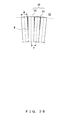
- FIG. 39 is a perspective view of another variation of the prism plate included in the illumination optical system illustrated in FIG. 29 .
- FIG. 40 is a plan view of the prism plate illustrated in FIG. 39 .
- a prism plate 62 illustrated in FIG. 37 and FIG. 38 is different from the prism plate 54 illustrated in FIG. 30 in the sense that the prism plate 62 includes a prism surface 65 in place of the prism surface 57.
- the prism surface 65 includes: inclined portions 63 that correspond to the slopes of a peak formed by each of the plurality of prism columns and that are inclined with respect to the tangential direction of the prism plate 62; and flat portions 64 that correspond to the flat top of the peaks and that are parallel to the tangential direction of the prism plate 62.
- the height of the peaks of the prism columns is H2 from the outer-circumference surface to a midpoint M, i.e., is constant from the outer-circumference surface to the midpoint M, but the height decreases from the midpoint M to the internal-circumference surface; the height of the peaks is H3 ( ⁇ H2) at the internal-circumference surface.
- the prism plate 62 satisfies W>P, where W is an interval between the peaks and P is the width of the prism column.
- a prism plate 66 illustrated in FIG. 39 and FIG. 40 is different from the prism plate 54 illustrated in FIG. 30 in the sense that the prism plate 66 includes a prism surface 69 in place of the prism surface 57.
- the prism surface 69 is different from the prism surface 57 illustrated in FIG. 30 in the sense that the prism surface 69 includes: inclined portions 67 that correspond to the slopes of a peak formed by each of the plurality of prism columns and that are inclined with respect to the tangential direction of the prism plate 66; and flat portions 68 that correspond to troughs formed between the plurality of prism columns and that are parallel to the tangential direction of the prism plate 66. That is, when the prism plate 66 is viewed from a cross section orthogonal to the radius direction of the prism columns, each prism column assumes a triangular shape, and the flat portions 68 are provided between the plurality of prism columns.
- the height of the peaks (the depth of the troughs) is H4 from the outer-circumference surface to a midpoint M, i.e., is constant from the outer-circumference surface to the midpoint M, but the height decreases (becomes shallower) from the midpoint M to the internal-circumference surface; the height of the peaks is H5 ( ⁇ H4) at the internal-circumference surface.
- all of the peaks of the prism column of the prism plate 66 include a top portion at the same position.
- the prism plate 62 satisfies W>P, where W is an interval between the peaks and P is the width of the prism column.
- the prism plate 66 With reference to the prism plate 66, illumination light that enters at the inclined portion 67 is deflected in the tangential direction due to refraction by the prism surface 69, while illumination light that enters at the flat portion 68 passes through the prism plate 66 without being deflected in the tangential direction due to refraction by the prism surface 69.
- the prism plate 66 also allows the directivity of illumination light to be arbitrarily controlled.
- the proportion of the area of the flat portions decreases, but variations are not particularly limited to these.
- the area of the flat portions may be increased by forming a prism surface that satisfies W ⁇ P, where W is an interval between the peaks and P is the width of the prism column.
- W is an interval between the peaks
- P is the width of the prism column.
- the proportion of the area of the flat portions may be arbitrarily changed by variously changing the parameters of the prism surface, such as W, which indicates the interval between the peaks; P, which indicates the width of the prism columns; and H, which indicates the height of the peaks. Accordingly, the directivity of illumination light may be arbitrarily controlled.
- the outgoing surface of the prism plate of the illumination optical system in accordance with the present embodiment may be formed as a blasted surface (a diffusing surface) on which minute asperities are formed. This may weaken the directivity so that the directivity distribution can become closer to a circle.
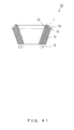
- FIG. 41 illustrates a configuration of a variation of the illumination optical system included in the image pickup apparatus illustrated in FIG. 29 .
- FIG. 42 is a perspective view of a prism plate included in the illumination optical system illustrated in FIG. 41 .
- An illumination optical system 70 illustrated in FIG. 41 includes: a plurality of LEDs 71 surrounding an image sensor (not illustrated) and arranged in a circular loop pattern; a prism plate 73 shaped like a circular loop; and a light guide 72 shaped like a circular tube between the plurality of LEDs 72 and the prism plate 73.
- the prism plate 73 includes a prism surface 74 on a side facing the light guide 72 and an outgoing surface 75 on a side facing an object.
- the illumination optical system 70 is different from the illumination optical system illustrated in FIG. 29 in the sense that the outgoing surface of the light guide 72 is inclined in the radial direction and that the prism surface 74 and the outgoing surface 75 of the prism plate 73 are inclined in the radial direction, as illustrated in FIG. 41 .
- the prism plate 73 is shaped like a truncated cone as illustrated in FIG. 42 .
- the illumination optical system 70 in accordance with the present variation may arbitrarily control the directivity of illumination light.
- the illumination optical system 70 includes the truncated-cone-shaped prism plate 73 that may arbitrarily adjust the balance between the amount of illumination light emitted in the positive radial direction and the amount of illumination light emitted in the negative radial direction. Such an adjustment may be made in accordance with the distance from the outgoing surface 75 to an object.
Landscapes
- Engineering & Computer Science (AREA)
- General Engineering & Computer Science (AREA)
- Multimedia (AREA)
- Signal Processing (AREA)
- Physics & Mathematics (AREA)
- General Physics & Mathematics (AREA)
- Theoretical Computer Science (AREA)
- Optical Elements Other Than Lenses (AREA)
- Stroboscope Apparatuses (AREA)
- Planar Illumination Modules (AREA)
- Image Input (AREA)
- Studio Devices (AREA)
Abstract
Description
- The inventions discussed herein are related to an illumination optical system for an image pickup apparatus.
- Image pickup apparatuses designed to read information from a subject, such as palm-vein authentication apparatuses and barcode readers (hereinafter simply referred to as "image pickup apparatuses), are known kinds of image pickup apparatuses. An image pickup apparatus includes, for example, an illumination
optical system 101 and an image pickupoptical system 103, as illustrated inFIG. 1 . Alight source 102, such as an LED, irradiates asubject 106 with irradiation light, and animage sensor 105 provided on the image side of animage pickup lens 104 detects regular reflection light and scattered light which are both incident via the subject 106 (e.g., a palm or a sheet on which a barcode is printed). Thereby, animage pickup apparatus 100 illustrated inFIG. 1 reads information of thesubject 106. - In the meantime, as illustrated in
FIG. 1 , both regular reflection light (solid lines inFIG. 1 ) and scattered light (dashed lines inFIG. 1 ) having a lower light intensity than the regular reflection light are generated from each point on the surface of thesubject 106 irradiated with irradiation light, but not all of the regular reflection light rays generated from the points in the field of view of the image pickupoptical system 103 enter theimage sensor 105. Thus, even when a point from which regular reflection light to be detected by theimage sensor 105 is emitted (point B inFIG. 1 ) and a point from which regular reflection light not to be detected by theimage sensor 105 is emitted (points A and C inFIG. 1 ) are illuminated at the same illuminance, the amount of detected light becomes different between these two points. - Such a difference in the amount of light caused by regular reflection light (hereinafter referred to as "regular-reflection noise") is one factor that deteriorates the reading precision of the image pickup apparatus. Thus, in the field of image pickup apparatuses, a technology has been pursued for limiting regular-reflection noise so as to improve the reading precision of the image pickup apparatuses.
- In order to improve the reading precision of the image pickup apparatus by limiting regular-reflection noise, it is necessary to prevent high-luminance regions from being locally generated on a subject, but simply equalizing illuminance is insufficient. The directivity of illumination light needs to be controlled to appropriately guide light generated from a subject to the image-pickup optical system. As a technology for controlling the directivity of light, a technology is known wherein the direction in which light is emitted is controlled using a prism plate, and such a technology is disclosed by, for example,
patent document 1. -
FIG. 2 ,FIG. 3 ,FIG. 4 , andFIG. 5 illustrate controlling the direction in which light is emitted by a prism plate in accordance with a prior art.FIG. 2 illustrates a relationship between incident light and outgoing light on an XZ cross-section of a prism plate.FIG. 3 illustrates a relationship on an XZ cross-section of the prism plate between outgoing light and the light perpendicularly incident onto the prism plate.FIG. 4 illustrates a relationship on a YZ cross-section taken on line AA' inFIG. 3 between outgoing light and the light perpendicularly incident onto the prism plate.FIG. 5 illustrates a relationship between incident light and outgoing light with the prism plate illustrated inFIG. 2 being viewed from above. The XYZ coordinate systems ofFIG. 2 to FIG. 5 are right-handed orthogonal coordinate systems provided for the convenience of reference to directions. - A
prism plate 200 illustrated inFIG. 2 includes: aprism surface 201 as an incidence surface on which a plurality of parallel prism columns each having aridge line 202 are arranged in the X direction; and aplane surface 203 as an outgoing surface. Theprism plate 200 allows incident light that enters from the prism-surface-201 side to be deflected by refraction at theprism surface 201 and theplane surface 203 so as to control the outgoing direction, with the result that the directivity of the outgoing light can be controlled. - Patent document 1: Japanese Laid-open Patent Publication No.
2004-171192 - The
prism plate 200 illustrated inFIG. 2 cannot emit outgoing light in a Y direction that is parallel to the ridge line 202 (hereinafter referred to as a "ridge-line direction") . In particular, as illustrated inFIG. 3 andFIG. 4 , the light perpendicularly incident on the prism plate 200 (to be exact, incident light that does not have a Y-direction component; see the solid lines inFIG. 2 ) is deflected only in an X direction that is orthogonal to theridge line 202. Thus, the outgoing light is not emitted in the ridge-line direction that is parallel to theridge line 202. Similarly, incident light that is not incident on the prism plate 200 (to be exact, incident light that has a Y-direction component; see the dashed lines inFIG. 2 ) is deflected by theprism surface 201 in an X direction. Thus, as illustrated inFIG. 5 , outgoing light has a Y-direction component in accordance with the Y-direction component of incident light but is not emitted in the ridge-line direction that is parallel to theridge line 202. - As described above, technologies that use a conventional prism plate such as those disclosed by cited
document 1 do not allow light to be emitted in the ridge-line direction, so the directivity of light cannot be arbitrarily controlled. - To improve the control, a method may possibly be used wherein blasting is applied to the outgoing surface of a prism plate so as to diffuse outgoing light.
FIG. 6 illustrates a prism plate that includes an outgoing surface formed as a blasted surface.FIG. 7 ,FIG. 8 , andFIG. 9 illustrate controlling the direction in which outgoing light is emitted by the prism plate illustrated inFIG. 6 .FIG. 7 illustrates a relationship between outgoing light and incident light that enters the prism plate perpendicularly on an XZ cross-section of the prism plate illustrated inFIG. 6 .FIG. 8 illustrates a relationship on a YZ cross-section taken on line BB' inFIG. 7 between outgoing light and the light incident perpendicularly onto the prism plate.FIG. 9 illustrates the directivity of outgoing light with the prism plate illustrated inFIG. 6 being viewed from above. The XYZ coordinate systems ofFIG. 6 to FIG. 9 are right-handed orthogonal coordinate systems provided for the convenience of reference to directions. - A
prism plate 300 illustrated inFIG. 6 includes: aprism surface 301 as an incidence surface on which a plurality of parallel prism columns having aridge line 302 are arranged in the X direction; and ablasted surface 303 as an outgoing surface. With reference to theprism plate 300, as illustrated inFIG. 7 andFIG. 8 , incident light deflected in the X direction by theprism surface 301 is diffused by theblasted surface 303, so outgoing light is also emitted in the ridge-line direction that is parallel to theridge line 302. - However, the light incident on the
blasted surface 303 has a strong X-direction directivity due to deflection by theprism surface 301. Thus, as illustrated inFIG. 9 , the distribution of the amount of outgoing light emitted from theblasted surface 303 in various directions (hereinafter referred to as a "directivity distribution") is shaped like an ellipse having a short axis extending in the ridge-line direction (the Y direction), thereby disadvantageously maintaining a strong X-direction directivity even after diffusion by theblasted surface 303. - Accordingly, the
prism plate 300 having theblasted surface 303 as an outgoing surface can control light directivities only in a limited way, so the light directivities cannot be arbitrarily controlled. Thus, the application to an illumination optical system of an image pickup apparatus does not allow the directivity of illumination light to be controlled arbitrarily in conformity with the image pickup apparatus. - In view of such a fact, an object of the present invention is to provide an illumination optical system for an image pickup apparatus, the illumination optical system being capable of arbitrarily controlling the directivity of illumination light.
- An aspect of the present invention provides an illumination optical system for an image pickup apparatus, the illumination optical system including: a plurality of light sources arranged in a circular loop pattern; and a prism plate shaped like a circular loop, wherein the prism plate includes: a prism surface at which illumination light from the light sources enters and on which a plurality of prism columns arranged in a circular loop pattern in a circumference direction of the prism plate are formed; and an outgoing surface from which the illumination light is emitted, wherein the prism surface includes a flat portion on at least one of a peak formed by each of the plurality of prism columns and a trough formed between the plurality of prism columns, the flat portion being substantially parallel to a tangential direction of the prism plate.
- In accordance with the present invention, an illumination optical system for an image pickup apparatus may be provided that is capable of arbitrarily controlling the directivity of illumination light.
-
-
FIG. 1 illustrates an exemplary configuration of an image pickup apparatus in accordance with a prior art designed to read information from a subject. -
FIG. 2 illustrates a relationship on an XZ cross-section of a prism plate in accordance with a prior art between incident light and outgoing light. -
FIG. 3 illustrates a relationship on an XZ cross-section of the prism plate illustrated inFIG. 2 between outgoing light and the light incident perpendicularly onto the prism plate. -
FIG. 4 illustrates a relationship on a YZ cross-section taken on line AA' inFIG. 3 between outgoing light and the light incident perpendicularly onto the prism plate illustrated inFIG. 2 . -
FIG. 5 illustrates a relationship between incident light and outgoing light with the prism plate illustrated inFIG. 2 being viewed from above. -
FIG. 6 illustrates a prism plate in accordance with a prior art that includes an outgoing surface formed as a blasted surface. -
FIG. 7 illustrates a relationship on an XZ cross-section of the prism plate illustrated inFIG. 6 between outgoing light and the light incident perpendicularly onto the prism plate. -
FIG. 8 illustrates a relationship on an XY cross-section taken on line BB' inFIG. 7 between outgoing light and the light incident perpendicularly onto the prism plate illustrated inFIG. 6 . -
FIG. 9 illustrates the directivity of outgoing light with the prism plate illustrated inFIG. 6 being viewed from above. -
FIG. 10 illustrates a configuration of an image pickup apparatus in accordance withembodiment 1. -
FIG. 11 is a perspective view of a prism plate included in an illumination optical system illustrated inFIG. 10 . -
FIG. 12 is a plan view of the prism plate included in the illumination optical system illustrated inFIG. 10 . -
FIG. 13 illustrates a relationship on a cross section taken on line CC' inFIG. 11 between outgoing light and the light incident onto the prism plate illustrated inFIG. 10 . -
FIG. 14 illustrates the directivity of outgoing light with the prism plate illustrated inFIG. 10 being viewed from above. -
FIG. 15 illustrates a relationship between outgoing light and the light incident on a prism plate including a flat portion that occupies a higher proportion of a prism surface than the flat portion of the prism plate illustrated inFIG. 10 does. -
FIG. 16 illustrates the directivity of outgoing light with the prism plate illustrated inFIG. 15 being viewed from above. -
FIG. 17 is a perspective view of a variation of the prism plate included in the illumination optical system illustrated inFIG. 10 . -
FIG. 18 illustrates a relationship between outgoing light and the light incident on the prism plate illustrated inFIG. 17 . -
FIG. 19 illustrates a relationship between outgoing light and the light incident on a prism plate including a flat portion that occupies a higher proportion of a prism surface than the flat portion of the prism plate illustrated inFIG. 17 does. -
FIG. 20 illustrates a relationship between outgoing light and the light incident on another variation of the prism plate included in the illumination optical system illustrated inFIG. 10 . -
FIG. 21 illustrates a relationship between outgoing light and the light incident on a still another variation of the prism plate included in the illumination optical system illustrated inFIG. 10 . -
FIG. 22 is a perspective view of a prism plate included in an illumination optical system in accordance withembodiment 2. -
FIG. 23 illustrates a relationship between outgoing light and the light incident on the prism plate illustrated inFIG. 22 . -
FIG. 24 illustrates a relationship on a cross section taken on line DD' inFIG. 23 between outgoing light and the light incident onto the prism plate illustrated inFIG. 22 . -
FIG. 25 illustrates the directivity of outgoing light with the prism plate illustrated inFIG. 22 being viewed from above. -
FIG. 26 illustrates a relationship between outgoing light and the light incident on a variation of the prism plate included in the illumination optical system in accordance withembodiment 2. -
FIG. 27 illustrates a relationship on a cross section taken on line EE' inFIG. 26 between outgoing light and the light incident onto the prism plate illustrated inFIG. 26 . -
FIG. 28 illustrates the directivity of outgoing light with the prism plate illustrated inFIG. 26 being viewed from above. -
FIG. 29 illustrates a configuration of an image pickup apparatus in accordance withembodiment 3. -
FIG. 30 is a perspective view of a prism plate included in an illumination optical system illustrated inFIG. 29 . -
FIG. 31 is a plan view of the prism plate illustrated inFIG. 30 . -
FIG. 32 is an enlarged plan view of the portion of the prism plate illustrated inFIG. 31 that is indicated by the dashed line. -
FIG. 33A illustrates the directivity of emitted light in the absence of a flat portion of the prism surface of the prism plate illustrated inFIG. 30 . -
FIG. 33B illustrates the directivity of emitted light under a condition in which a flat portion occupies a low proportion of a prism surface of the prism plate illustrated inFIG. 30 . -
FIG. 33C illustrates the directivity of emitted light under a condition in which a flat portion occupies an intermediate proportion of the prism surface of the prism plate illustrated inFIG. 30 . -
FIG. 33D illustrates the directivity of emitted light under a condition in which a flat portion occupies a high proportion of the prism surface of the prism plate illustrated inFIG. 30 . -
FIG. 34 illustrates a relationship between an illuminance evaluation plane and an outgoing surface of an illumination optical system. -
FIG. 35A illustrates an illuminance distribution on an evaluation plane under a condition in which illumination light emitted from an illumination optical system indicates the directivity illustrated inFIG. 33A . -
FIG. 35B illustrates an illuminance distribution on an evaluation plane under a condition in which illumination light emitted from an illumination optical system indicates the directivity illustrated inFIG. 33B . -
FIG. 35C illustrates an illuminance distribution on an evaluation plane under a condition in which illumination light emitted from an illumination optical system indicates the directivity illustrated inFIG. 33C . -
FIG. 35D illustrates an illuminance distribution on an evaluation plane under a condition in which illumination light emitted from an illumination optical system indicates the directivity illustrated inFIG. 33D . -
FIG. 36 illustrates a change in an illuminance distribution that is made on an evaluation plane by a change in the directivity of illumination light emitted from an illumination optical system. -
FIG. 37 is a perspective view of a variation of the prism plate included in the illumination optical system illustrated inFIG. 29 . -
FIG. 38 is a plan view of the prism plate illustrated inFIG. 37 . -
FIG. 39 is a perspective view of another variation of the prism plate included in the illumination optical system illustrated inFIG. 29 . -
FIG. 40 is a plan view of the prism plate illustrated inFIG. 39 . -
FIG. 41 illustrates a configuration of a variation of the illumination optical system included in the image pickup apparatus illustrated inFIG. 29 . -
FIG. 42 is a perspective view of a prism plate included in the illumination optical system illustrated inFIG. 41 . -
FIG. 10 illustrates a configuration of an image pickup apparatus in accordance with the present embodiment.FIG. 11 is a perspective view of a prism plate included in an illumination optical system illustrated inFIG. 10 in accordance with the present embodiment.FIG. 12 is a plan view of the prism plate included in the illumination optical system illustrated inFIG. 10 in accordance with the present embodiment. - An
image pickup apparatus 10 illustrated inFIG. 10 is an image pickup apparatus designed to read information from anobject 21, e.g., a palm-vein authentication apparatus or a barcode reader. Theimage pickup apparatus 10 includes: an image-pickup optical system that includes an image-pickup lens 19 and animage sensor 20; and an illumination optical system surrounding the image-pickup optical system. - The illumination optical system includes: a plurality of
LEDs 11 surrounding theimage sensor 20 and arranged in a rectangular loop pattern; aprism plate 14 shaped like a rectangular loop; and alight guide 12 located between the plurality ofLEDs 11 and theprism plate 14 and shaped like a rectangular tube surrounding the image-pickup lens 19. Theprism plate 14 includes aprism surface 17 on a side facing thelight guide 12, and, on a side facing theobject 21, anoutgoing surface 18 that is a plane parallel to an XY plane. - As illustrated in
FIG. 11 andFIG. 12 , a plurality of prism columns are formed on theprism surface 17 and are arranged in a side direction of the rectangular-loop-shapedprism plate 14. The direction in which the prism columns of the rectangular-loop-shapedprism plate 14 are arranged (corresponding to an X direction inFIG. 11 ) will hereinafter be referred to as a "line-up direction"; the direction in which the prism columns extend will hereinafter be referred to as a "ridge-line direction" (corresponding to a Y direction inFIG. 11 ). - As illustrated in
FIG. 11 , theprism surface 17 includes:inclined portions 15 that correspond to the slopes of a peak formed by each of the plurality of prism columns and that are inclined with respect to the line-up direction;flat portions 16 that correspond to the flat top of the peaks and that are parallel to the line-up direction. That is, when viewed from a cross section orthogonal to the ridge-line direction of the prism columns, each prism column assumes a trapezoidal shape, and theflat portion 16 is provided on each prism column. - In the illumination optical system illustrated in
FIG. 10 , illumination light that is emitted from theLEDs 11 and that enters thelight guide 12 advances within thelight guide 12 while repeating total reflection, thereby equalizing the directivities of the illumination light, and the illumination light is then emitted from anoutgoing surface 13 toward theprism surface 17 of theprism plate 14. Subsequently, theprism plate 14 controls the directivity of the illumination light that enters theprism plate 14 from theprism surface 17, and the illumination light is then emitted from theoutgoing surface 18 of theprism plate 14. Accordingly, theobject 21 is irradiated with illumination light for which a directivity has been controlled. - Next, descriptions will be given of the fact that the illumination optical system in accordance with the present embodiment allows the directivity of illumination light to be arbitrarily controlled.
FIG. 13 illustrates a relationship on a cross section taken on line CC' inFIG. 12 between outgoing light and the light incident onto the prism plate illustrated inFIG. 10 .FIG. 14 illustrates the directivity of outgoing light with the prism plate illustrated inFIG. 10 being viewed from above. - As illustrated in
FIG. 13 , with reference to theprism plate 14 of the illumination optical system in accordance with the present embodiment, illumination light that enters at theinclined portion 15 of theprism surface 17 is deflected in the line-up direction (the X direction) due to refraction by theprism surface 17, while illumination light that enters at theflat portion 16 of theprism surface 17 passes through theprism plate 14 without being deflected in the line-up direction due to refraction by theprism surface 17. In addition, even when illumination light that enters at theflat portion 16 passes through theflat portion 16 and theoutgoing surface 18, the ratio between a line-up-direction (X-direction) component and a ridge-line-direction (Y-direction) component of the illumination light that enters at theflat portion 16 is maintained since theflat portion 16 and theoutgoing surface 18 are parallel to each other. - Accordingly, the illumination optical system in accordance with the present embodiment allows the directivity of illumination light to be arbitrarily controlled.
- More particularly, as illustrated by the directivity distribution illustrated in
FIG. 14 , the illumination optical system in accordance with the present embodiment also allows illumination light to be emitted in the ridge-line direction. Moreover, in comparison with theprism plate 200 inFIG. 2 that deflects all pieces of incident illumination light in the line-up direction, theprism plate 14 may limit the amount of illumination light deflected in the line-up direction. Accordingly, in comparison with illumination optical systems in accordance with the prior art, the illumination optical system in accordance with the present embodiment may limit deflection of the directivity of illumination light in the line-up direction. - In addition, the
prism plate 14 allows the amount of illumination light deflected in the line-up direction to be arbitrarily adjusted in accordance with the proportion of an area occupied on theprism surface 17 by theflat portion 16. Thus, the illumination optical system in accordance with the present embodiment allows the proportion of the amount of illumination light emitted in the line-up direction to the amount of illumination light emitted in the ridge-line direction to be arbitrarily controlled.FIG. 15 illustrates a relationship between outgoing light and the light incident on a prism plate including a flat portion that occupies a higher proportion of a prism surface than the flat portion of the prism plate illustrated inFIG. 10 does.FIG. 16 illustrates the directivity of outgoing light with the prism plate illustrated inFIG. 15 being viewed from above. As illustrated inFIG. 15 , the amount of illumination light deflected in the line-up direction may be decreased by increasing the proportion of the area occupied by aflat portion 16a within aprism surface 17a of aprism plate 14a so as to decrease the amount of illumination light incident on aninclined portion 15a. Thus, as illustrated inFIG. 16 , a directivity distribution that is closer to a circle is achievable. - The
flat portion 16 of theprism plate 14 is basically parallel to the line-up direction but does not necessarily need to be parallel to the ridge-line direction. Inclining theflat portion 16 with respect to the ridge-line direction allows a balance to be adjusted between the amount of light emitted in a positive ridge-line direction (Y+) and the amount of light emitted in a negative ridge-line direction (Y-). Accordingly, the illumination optical system in accordance with the present embodiment also allows a balance to be arbitrarily controlled between the amount of illumination light emitted in the positive ridge-line direction (Y+) and the amount of illumination light emitted in the negative ridge-line direction (Y-). Such an adjustment may be made in accordance with, for example, the distance from theoutgoing surface 18 to theobject 21. As with theflat portion 16, theoutgoing surface 18 is basically parallel to the line-up direction but does not necessarily need to be parallel to the ridge-line direction. Inclining theoutgoing surface 18 with respect to the ridge-line direction may also achieve an advantageous effect similar to the advantageous effect achieved by inclining theflat portion 16 with respect to the ridge-line direction. - The descriptions above have been given with reference to an exemplary situation in which the directivities of illumination light emitted from the
light guide 12 are equalized, but the directivities of illumination light emitted from thelight guide 12 do not necessarily need to be equalized. Theprism plate 14 may arbitrarily control the directivity of emitted light relative to the directivity of incident light. Accordingly, designing theprism plate 14 in accordance with the directivity of illumination light emitted from thelight guide 12 allows the illumination optical system in accordance with the present embodiment to arbitrarily control the directivity of illumination light. - The
flat portion 16 and theoutgoing surface 18 are desirably parallel to the line-up direction but do not necessarily need to be completely parallel to the line-up direction. Theflat portion 16 and theoutgoing surface 18 may be inclined with respect to the line-up direction, as long as they form a smaller angle of inclination than theinclined portion 15 does and as long as the angle of inclination is within a range such that a function is obtained to distribute a light amount in the ridge-line direction. - In addition, the illumination optical system in accordance with the present embodiment allows a desired directivity to be easily achieved at a low cost.
- It is typically difficult to quantify the performance of a blasted surface, and, in general, designing of a blasted surface inevitably depends on designating of a blast intensity. As a method for determining a designed value of a blast intensity, a method may possibly be adopted that uses a trial-manufacture experiment wherein blasting is applied at different blast intensities to materials similar to the material for an actual prism plate, e.g., plastic materials, and then these materials are compared with each other. However, applying blasting to a prism-plate mold at a blast intensity determined using such a method does not lead to an expectation that a prism plate formed by the mold will have a performance similar to the performance of the material used in the trial-manufacture experiment. This is because conditions such as hardness are completely different between the material used in the trial-manufacture experiment and the material for the mold. Thus, in order to determine a blast intensity that achieves a desired performance, it is necessary to apply blasting to molds themselves at different blast intensities and to compare these molds with each other, thereby causing a great burden in terms of both time and cost. By contrast, unlike the
prism plate 300 in accordance with the prior art illustrated inFIG.5 , theprism plate 14 does not include a blasted surface. Accordingly, the illumination optical system in accordance with the present embodiment that includes theprism plate 14 allows a desired directivity to be easily achieved at a low cost. Moreover, without relying on an indirect index such as a blast intensity, the prism plate may be designed by designating the shape of theprism plate 14 in accordance with, for example, the width and the angle of theinclined portion 15 and theflat portion 16. Thus, the design may be represented on a drawing, and, as a result, designed performances may be achieved with a high reproducibility. - In addition, the illumination optical system in accordance with the present embodiment may downsize the entirety of the image pickup apparatus.
- The illumination optical system in accordance with the prior art cannot emit illumination light in the ridge-line direction, so making the illumination optical system loop-shaped to surround an image pickup optical system disables illumination light emitted from a light source from being effectively utilized. By contrast, the illumination optical system in accordance with the present embodiment may emit illumination light in the ridge-line direction so that the directivity of illumination light can be arbitrarily controlled. Thus, as illustrated in
FIG. 10 , the illumination optical system may be shaped like a rectangular loop in such a manner that the image pickup optical system is located inside the rectangular loop, and hence the illumination optical system in accordance with the present embodiment may downsize the entirety of the image pickup apparatus while maintaining the efficiency for utilization of illumination light. - In the following, descriptions will be given of various variations of the prism plate included in the illumination optical system in accordance with the present embodiment.
FIG. 17 is a perspective view of a variation of the prism plate included in the illumination optical system illustrated inFIG. 10 .FIG. 18 illustrates a relationship between outgoing light and the light incident on the prism plate illustrated inFIG. 17 .FIG. 19 illustrates a relationship between outgoing light and the light incident on a prism plate including a flat portion that occupies a higher proportion of a prism surface than the flat portion of the prism plate illustrated inFIG. 17 does.FIG. 20 illustrates a relationship between outgoing light and the light incident on another variation of the prism plate included in the illumination optical system illustrated inFIG. 10 .FIG. 21 illustrates a relationship between outgoing light and the light incident on still another variation of the prism plate included in the illumination optical system illustrated inFIG. 10 . - A
prism plate 22 illustrated inFIG. 17 is different from theprism plate 14 in the sense that aprism surface 25 on a side facing a light guide includes:inclined portions 23 that correspond to the slopes of a peak formed by each of the plurality of prism columns and that are inclined with respect to the line-up direction; andflat portions 24 that correspond to troughs formed between the plurality of prism columns and that are parallel to the line-up direction. That is, when theprism plate 22 is viewed from a cross section orthogonal to the ridge-line direction of the prism columns, each prism column assumes a triangular shape, and theflat portions 24 are provided between the plurality of prism columns. As with theprism plate 14, theprism plate 22 includes, on a side facing an object, an outgoing surface (an outgoing surface 26) that is a plane parallel to the XY plane. - As illustrated in
FIG. 18 , with reference to theprism plate 22, illumination light that enters at theinclined portion 23 is deflected in the line-up direction (the X direction) due to refraction by theprism surface 25, while illumination light that enters at theflat portion 24 passes through theprism plate 22 without being deflected in the line-up direction due to refraction by theprism surface 25. Thus, theprism plate 22 may achieve an advantageous effect similar to the advantageous effect achieved by theprism plate 14. - In addition, as with the
prism plate 14, theprism plate 22 allows the amount of illumination light deflected in the line-up direction to be arbitrarily adjusted in accordance with the proportion of an area occupied on theprism surface 25 by theflat portion 24. For example, as indicated by aprism plate 22a illustrated inFIG. 19 , the amount of illumination light deflected in the line-up direction may be decreased by increasing the proportion of the area occupied by aflat portion 24a within aprism surface 25a of aprism plate 22a so as to decrease the amount of illumination light incident on aninclined portion 23a. - A
prism plate 27 illustrated inFIG. 20 is different from theprism plate 14 in the sense that theprism plate 27 includes, on a side facing an object, anoutgoing surface 31 that is a blasted surface (a diffusing surface) including minute asperities. As with theprism plate 14, a prism surface (a prism surface 30) formed on a side facing a light guide includes: an inclined portion (an inclined portion 28) inclined with respect to the line-up direction; and a flat portion (a flat portion 29) that is parallel to the line-up direction. - As illustrated in
FIG. 20 , with reference to theprism plate 27, illumination light for which a directivity has been adjusted by theprism surface 30 is diffused by theoutgoing surface 31. Thus, theprism plate 27 may weaken directivities more greatly than theprism plate 14 does. That is, a directivity distribution is achievable that is closer to a circle than a directivity distribution achieved by theprism plate 14 is. Prism plates such as theprism plate 27 are more advantageous when, for example, the directivity of illumination light emitted from thelight guide 12 illustrated inFIG. 10 is deflected significantly. - Even in the case of a prism plate such as a
prism plate 32 illustrated inFIG. 21 , i.e., a prism plate including, on a side facing a light guide, aprism surface 35 including: aninclined portion 33 inclined with respect to the line-up direction; and aflat portion 34 that corresponds to a trough and that is parallel to the line-up direction, an advantageous effect similar to the advantageous effect achieved by theprism plate 27 is achievable as long as a blasted surface on which minute asperities are formed is provided on the side facing an object. -
FIG. 22 is a perspective view of a prism plate included in an illumination optical system in accordance with the present embodiment.FIG. 23 illustrates a relationship between outgoing light and the light incident on the prism plate illustrated inFIG. 22 .FIG. 24 illustrates a relationship on a cross section taken on line DD' inFIG. 23 between outgoing light and the light incident onto the prism plate illustrated inFIG. 22 .FIG. 25 illustrates the directivity of outgoing light with the prism plate illustrated inFIG. 22 being viewed from above. Note that, except for the fact that aprism plate 40 illustrated inFIG. 22 is provided in place of theprism plate 14, the illumination optical system in accordance with the present embodiment is similar to the illumination optical system in accordance withembodiment 1 illustrated inFIG. 10 . - The
prism plate 40 illustrated inFIG. 22 includes: aprism surface 43 which is provided on a side facing a light guide and on which a plurality of prism columns are formed; and anoutgoing surface 44 which is provided on a side facing an object and which is a plane parallel to the XY plane. Theprism surface 43 includes:inclined portions 41 that correspond to the slopes of a peak formed by each of the plurality of prism columns; andridge lines 42 of the peaks, and each prism column assumes a triangular shape when viewed from a cross section orthogonal to the ridge-line direction of the prism columns. Theinclined portions 41 are formed as a blasted surface (a diffusing surface) on which minute asperities are formed. - As illustrated in
FIG. 23 andFIG. 24 , with reference to theprism plate 40 of the illumination optical system in accordance with the present embodiment, refraction and diffusion simultaneously occur when illumination light enters at theinclined portion 41 inclined with respect to the line-up direction. That is, theprism plate 40 causes illumination light that has passed through theinclined portion 41 to be emitted in various directions, including the ridge-line direction, and deflects the center of the distribution of the amount of light (hereinafter referred to as an "optical axis") in the line-up direction. Thus, as illustrated inFIG. 25 , the directivity distribution of illumination light emitted from theoutgoing surface 44 is shaped like an ellipse, and illumination light is also emitted in the ridge-line direction. The blast intensity that is used to form theinclined portion 41 of theprism plate 40 as a blasted surface may be adjusted to adjust the amount of illumination light emitted in the ridge-line direction. - Accordingly, the illumination optical system in accordance with the present embodiment may arbitrarily control the directivity of illumination light. With reference to the
prism plate 40, diffusion does not occur after deflection but occurs simultaneously with deflection so that diffusion caused by the blasted surface can be more efficient than in the case of theprism plate 300 illustrated inFIG. 5 . Accordingly, in comparison with the illumination optical system that includes theprism plate 300, the illumination optical system in accordance with the present embodiment may broaden the range of directivity control, thereby achieving a directivity distribution that is closer to a circle. - In the following, descriptions will be given of a variation of the prism plate included in the illumination optical system in accordance with the present embodiment.
FIG. 26 illustrates a relationship between outgoing light and the light incident on a variation of the prism plate included in the illumination optical system in accordance with the present embodiment.FIG. 27 illustrates a relationship on a cross section taken on line EE' inFIG. 26 between outgoing light and the light incident onto the prism plate illustrated inFIG. 26 .FIG. 28 illustrates the directivity of outgoing light with the prism plate illustrated inFIG. 26 being viewed from above. - A
prism plate 45 illustrated inFIG. 26 andFIG. 27 is different from theprism plate 40 in the sense that theprism plate 45 includes, on a side facing an object, anoutgoing surface 46 that is a blasted surface (a diffusing surface) including minute asperities. As with theprism plate 40, theprism surface 43 includes, on the side facing the light guide, aninclined portion 41 formed as a blasted surface. - As illustrated in
FIG. 26 andFIG. 27 , with reference to theprism plate 45, not only theinclined portion 41 of theprism surface 43, i.e., an incidence surface, but also theoutgoing surface 46 is formed as a blasted surface, so refraction and diffusion occur on both theinclined portion 41 and theoutgoing surface 46. Accordingly, in comparison with the illumination optical system that includes theprism plate 40, the illumination optical system that includes theprism plate 45 may significantly broaden the range of directivity control, thereby achieving a directivity distribution that is closer to a circle as illustrated inFIG. 28 . -
FIG. 29 illustrates a configuration of an image pickup apparatus in accordance with the present embodiment.FIG. 30 is a perspective view of a prism plate included in an illumination optical system illustrated inFIG. 29 .FIG. 31 is a plan view of the prism plate illustrated inFIG. 30 .FIG. 32 is an enlarged plan view of the portion of the prism plate illustrated inFIG. 31 that is indicated by the dashed line. - An
image pickup apparatus 50 illustrated inFIG. 29 is an image pickup apparatus designed to read information from anobject 61, e.g., a palm-vein authentication apparatus or a barcode reader. Theimage pickup apparatus 50 includes: an image-pickup optical system that includes an image-pickup lens 59 and animage sensor 60; and an illumination optical system designed for the image pickup apparatus and surrounding the image-pickup optical system. - The illumination optical system includes: a plurality of
LEDs 51 surrounding theimage sensor 60 and arranged in a circular loop pattern; aprism plate 54 shaped like a circular loop; and alight guide 52 located between the plurality ofLEDs 51 and theprism plate 54 and shaped like a circular tube surrounding the image-pickup lens 59. Theprism plate 54 includes aprism surface 57 on a side facing thelight guide 52, and, on a side facing theobject 61, anoutgoing surface 58 that is a plane orthogonal to an optical axis of the image pickup optical system. It is noted that theprism plate 54 is the same as theprism plate 14 ofembodiment 1 except that it is shaped like a circular loop. - As illustrated in
FIG. 30 andFIG. 31 , a plurality of prism columns are formed on theprism surface 57. The plurality of prism columns are arranged in a circular loop pattern in the circumference direction of the circular-loop-shapedprism plate 54, and the prism columns are each extended in the radial direction of the circular-loop-shapedprism plate 54. - The
prism surface 57 includes:inclined portions 55 that correspond to the slopes of a peak formed by each of the plurality of prism columns and that are inclined with respect to the tangential direction of theprism plate 54; andflat portions 56 that correspond to the flat top of the peaks and that are parallel to the tangential direction of theprism plate 54. That is, when viewed from a cross section orthogonal to the radial direction of theprism plate 54, each prism column assumes a trapezoidal shape, and theflat portion 56 is provided on each prism column. - As illustrated in
FIG. 30 , the height of the peaks of the prism columns arranged in a circular loop pattern in the circumference direction is constant over the prism plate 54 (i.e., constant from the outer circumference to the internal circumference); in particular, the height of the peaks is H1 over the entirety of theprism plate 54. The intervals between the peaks are also constant; in particular, the intervals are interval W. As illustrated inFIG. 32 , the outer circumference of the circular-loop-shapedprism plate 54 is understandably longer than the internal circumference, and hence, although the width of the inside of each prism column is width P, the width of each prism column becomes longer from the internal circumference of theprism plate 54 to the outer circumference. With reference to theprism plate 54, the increment between width P and the width of the prism columns that becomes longer from the internal circumference to the outer circumference is the width of theflat portion 56. Intervals between peaks W and width P of the prism column satisfy W=P. - In an illumination optical system configured as described above, illumination light that is emitted from the
LEDs 51 and enters thelight guide 52 advances within thelight guide 52 while repeating total reflection, thereby equalizing the directivities of the illumination light, and the illumination light is then emitted from anoutgoing surface 53 toward theprism surface 57 of theprism plate 54. Subsequently, theprism plate 54 controls the directivity of the illumination light that enters theprism plate 54 from theprism surface 57, and the illumination light is then emitted from theoutgoing surface 58 of theprism plate 54. Accordingly, theobject 61 is irradiated with illumination light for which a directivity has been controlled. - With reference to the
prism plate 54, illumination light that enters at theinclined portion 55 of theprism surface 57 is deflected in the tangential direction due to refraction by theprism surface 57, while illumination light that enters at theflat portion 56 of theprism surface 57 passes through theprism plate 54 without being deflected in the tangential direction due to refraction by theprism surface 57. In addition, even when illumination light that enters at theflat portion 56 passes through theflat portion 56 and theoutgoing surface 58, the ratio between a tangential-direction component and a radial-direction component of the illumination light is maintained since theflat portion 56 and theoutgoing surface 58 are parallel to each other. - Accordingly, as with the illumination optical system in accordance with
embodiment 1, the illumination optical system in accordance with the present embodiment allows the directivity of illumination light to be arbitrarily controlled. More particularly, the illumination optical system in accordance with the present embodiment also allows illumination light to be emitted in the radial direction, thereby limiting deflection of the directivity of illumination light in the tangential direction. - In addition, the illumination optical system in accordance with the present embodiment allows the amount of illumination light deflected in the tangential direction to be arbitrarily adjusted in accordance with the proportion of an area occupied on the
prism surface 57 by theflat portion 56. Thus, as with the illumination optical system in accordance withembodiment 1, the illumination optical system in accordance with the present embodiment allows the proportion of the amount of illumination light emitted in the tangential direction to the amount of illumination light emitted in the radial direction to be arbitrarily controlled. -
FIG. 33A illustrates the directivity of emitted light in the absence of a flat portion of the prism surface of the prism plate illustrated inFIG. 30 .FIG. 33B illustrates the directivity of emitted light under a condition in which a flat portion occupies a low proportion of a prism surface of the prism plate illustrated inFIG. 30 .FIG. 33C illustrates the directivity of emitted light under a condition in which a flat portion occupies an intermediate proportion of the prism surface of the prism plate illustrated inFIG. 30 .FIG. 33D illustrates the directivity of emitted light under a condition in which a flat portion occupies a high proportion of the prism surface of the prism plate illustrated inFIG. 30 . - In the case of an illumination optical system that employs, in place of the
prism plate 54, aprism plate 54a that does not include a flat portion on the prism surface, illumination light is not emitted in the radial direction even when incident light from various directions enters theprism plate 54a, and hence illumination light emitted from the illumination optical system is distributed in a figure eight pattern, with a portion narrowed in the radial direction, as illustrated inFIG. 33A . - In the case of an illumination optical system that employs a
prism plate 54 wherein a flat portion occupies a low proportion of a prism surface, a relatively small amount of illumination light is emitted in the radial direction. Thus, as illustrated inFIG. 33B , illumination light emitted from the illumination optical system has an ellipse-shaped directivity distribution that indicates a strong tangential-direction directivity in comparison with a radial-direction directivity. - In the case of an illumination optical system that employs, in place of the
prism plate 54, aprism plate 54b wherein a flat portion occupies an intermediate proportion of a prism surface, a certain amount of illumination light is also emitted in the radial direction. Thus, as illustrated inFIG. 33C , illumination light emitted from the illumination optical system has a directivity distribution that indicates a strong tangential-direction directivity relative to a radial-direction directivity but has an ellipsoid shape that is relatively close to a circle. - In the case of an illumination optical system that employs, in place of the
prism plate 54, aprism plate 54c wherein a flat portion occupies a high proportion of a prism surface, a sufficient amount of illumination light is also emitted in the radial direction. Thus, as illustrated inFIG. 33D , illumination light emitted from the illumination optical system has a directivity distribution substantially shaped like a cycle. - Next, descriptions will be given of an illuminance distribution on the
object 61 under a condition in which theobject 61 is irradiated with illumination light having the directivity distributions illustrated inFIG. 33A to FIG. 33D . -
FIG. 34 illustrates a relationship between an illuminance evaluation plane and an outgoing surface of an illumination optical system.FIG. 35A illustrates an illuminance distribution on an evaluation plane under a condition in which illumination light emitted from an illumination optical system indicates the directivity illustrated inFIG. 33A .FIG. 35B illustrates an illuminance distribution on an evaluation plane under a condition in which illumination light emitted from an illumination optical system indicates the directivity illustrated inFIG. 33B .FIG. 35C illustrates an illuminance distribution on an evaluation plane under a condition in which illumination light emitted from an illumination optical system indicates the directivity illustrated inFIG. 33C .FIG. 35D illustrates an illuminance distribution on an evaluation plane under a condition in which illumination light emitted from an illumination optical system indicates the directivity illustrated inFIG. 33D .FIG. 36 illustrates a change in an illuminance distribution that is made on an evaluation plane by a change in the directivity of illumination light emitted from an illumination optical system. - As illustrated in
FIG. 34 , an optical-axis direction of the image pickup optical system is defined as a z-axis direction, z coordinates of theoutgoing surface 58 of the illumination optical system are defined as 0, and z coordinates of the evaluation plane that correspond to the surface of theobject 61 are defined as z1. In addition, a radial direction that is orthogonal to the optical-axis direction of the image pickup optical system is defined as an r direction, and r coordinates of the optical axis of the image pickup optical system are defined as 0. - When illumination light that has the directivity distribution illustrated in
FIG. 33A enters the evaluation plane, the illuminance of a central portion of the evaluation plane is 0, as illustrated inFIG. 35A . Thus, for the directivity distribution illustrated inFIG. 33A , a central portion of theobject 61 is not illuminated at all. - Meanwhile, when illumination light that is also distributed in the radial direction as illustrated in
FIG. 33B to FIG. 33D enters the evaluation plane, illuminance is also generated in a central portion of the evaluation plane as illustrated inFIG. 35B to FIG. 35D so that the entirety of theobject 61 can be illuminated. - When illumination light that has a directivity distribution substantially shaped like a cycle illustrated in
FIG. 33D enters the evaluation plane, an illuminance distribution D does not become flat and a central portion of the evaluation plane indicates a high illuminance, as illustrated inFIG. 35D . This is because the illumination optical system is shaped like a circular loop. When illumination light illustrated inFIG. 33C having a directivity distribution shaped like an ellipse that is relatively close to a circle and that has a short axis extending in the radial direction enters the evaluation plane, a substantially planar illumination distribution C is generated on the evaluation plane, as illustrated inFIG. 35C . - As described above, the illumination optical system in accordance with the present embodiment allows the proportion of the area occupied on the prism surface by the flat portion to be changed so as to change the amount of illumination light emitted in the radial direction, so that the directivity distribution of the illumination light can be controlled, with the result that the illumination distribution on the evaluation plane (the object) can be arbitrarily controlled as illustrated in
FIG. 36 . - The
flat portion 56 of theprism plate 54 is basically parallel to the tangential direction but does not necessarily need to be parallel to the radial direction. Inclining theflat portion 56 with respect to the radial direction allows a balance to be adjusted between the amount of light emitted in a positive radial direction (a direction from the internal circumference to the outer circumference of the prism plate 54) and the amount of light emitted in a negative radial direction (a direction from the outer circumference to the internal circumference of the prism plate 54). Accordingly, the illumination optical system in accordance with the present embodiment also allows a balance to be arbitrarily controlled between the amount of illumination light emitted in the positive radial direction and the amount of illumination light emitted in the negative radial direction. Such an adjustment may be made in accordance with, for example, the distance from theoutgoing surface 58 to theobject 61. As with theflat portion 56, theoutgoing surface 58 is basically parallel to the tangential direction but does not necessarily need to be parallel to the radial direction. Inclining theoutgoing surface 58 with respect to the radial direction may also achieve an advantageous effect similar to the advantageous effect achieved by inclining theflat portion 56 with respect to the tangential direction. - The present embodiment has been described with reference to an exemplary situation in which the directivities of illumination light emitted from the
outgoing surface 58 are equalized, but the directivities of illumination light emitted from thelight guide 52 do not necessarily need to be equalized. Theprism plate 54 may arbitrarily control the directivity of emitted light relative to the directivity of incident light. Accordingly, designing theprism plate 54 in accordance with the directivity of illumination light emitted from thelight guide 52 allows the illumination optical system in accordance with the present embodiment to arbitrarily control the directivity of illumination light. - The
flat portion 56 and theoutgoing surface 58 are desirably parallel to the tangential direction but do not necessarily need to be completely parallel to the tangential direction. Theflat portion 56 and theoutgoing surface 58 may be inclined with respect to the tangential direction, as long as they form a smaller angle of inclination than theinclined portion 55 does and as long as the angle of inclination is within a range such that a function is obtained to distribute a light amount in the radial direction. - In addition, the illumination optical system in accordance with the present embodiment does not include a blasted surface, so, for a reason similar to the reason described with reference to
embodiment 1, the illumination optical system in accordance with the present embodiment allows a desired directivity to be easily achieved at a low cost. Moreover, the design may be represented on a drawing, and, as a result, designed performances may be achieved with high reproducibility. - In addition, the illumination optical system in accordance with the present embodiment may downsize the entirety of the image pickup apparatus. The illumination optical system in accordance with the prior art cannot emit illumination light in the ridge-line direction (corresponding to the radius direction for the illumination optical system in accordance with the present embodiment), so making the illumination optical system loop-shaped to surround an image pickup optical system disables illumination light emitted from a light source from being effectively utilized. By contrast, the illumination optical system in accordance with the present embodiment may emit illumination light in the radius direction so that the directivity of illumination light can be arbitrarily controlled. Thus, as illustrated in
FIG. 29 , the illumination optical systemmay be shaped like a circular loop in such a manner that the image pickup optical system is located inside the circular loop, and hence the illumination optical system in accordance with the present embodiment may downsize the entirety of the image pickup apparatus while maintaining the efficiency of utilization of illumination light. - In the case of an illumination optical system shaped like a rectangular loop, for example, the distance from a central portion of each side of the rectangle to the image-
pickup lens 59 is different from the distance from an end of each side of the rectangle to the image-pickup lens 59, and the relationship between the image-pickup lens 59 and the optical axis of illumination light emitted from the central portion of each side is different from the relationship between the image-pickup lens 59 and the optical axis of illumination light emitted from the end of each side, so the illumination light emitted from the central portion of each side and the illumination light emitted from the end of each side have different influences on picking up an image. By contrast, in the case of an illumination optical system shaped like a circular loop, even pieces of illumination light emitted from different positions arranged in the circumference direction do not affect the picking up of an image differently, so the illumination optical system may easily achieve an optimum condition for picking up an image by controlling the directivity of illumination light. Accordingly, the illumination optical system in accordance with the present embodiment is more suitable as an illumination optical system of an image pickup optical system. - In the following, descriptions will be given of various variations of the prism plate included in the illumination optical system in accordance with the present embodiment.
-
FIG. 37 is a perspective view of a variation of the prism plate included in the illumination optical system illustrated inFIG. 29 .FIG. 38 is a plan view of the prism plate illustrated inFIG. 37 .FIG. 39 is a perspective view of another variation of the prism plate included in the illumination optical system illustrated inFIG. 29 .FIG. 40 is a plan view of the prism plate illustrated inFIG. 39 . - A
prism plate 62 illustrated inFIG. 37 andFIG. 38 is different from theprism plate 54 illustrated inFIG. 30 in the sense that theprism plate 62 includes aprism surface 65 in place of theprism surface 57. As with theprism surface 57 illustrated inFIG. 30 , theprism surface 65 includes:inclined portions 63 that correspond to the slopes of a peak formed by each of the plurality of prism columns and that are inclined with respect to the tangential direction of theprism plate 62; andflat portions 64 that correspond to the flat top of the peaks and that are parallel to the tangential direction of theprism plate 62. - With reference to the
prism plate 62, as illustrated inFIG. 37 , the height of the peaks of the prism columns is H2 from the outer-circumference surface to a midpoint M, i.e., is constant from the outer-circumference surface to the midpoint M, but the height decreases from the midpoint M to the internal-circumference surface; the height of the peaks is H3 (<H2) at the internal-circumference surface. Theprism plate 62 satisfies W>P, where W is an interval between the peaks and P is the width of the prism column. - A
prism plate 66 illustrated inFIG. 39 andFIG. 40 is different from theprism plate 54 illustrated inFIG. 30 in the sense that theprism plate 66 includes aprism surface 69 in place of theprism surface 57. Theprism surface 69 is different from theprism surface 57 illustrated inFIG. 30 in the sense that theprism surface 69 includes:inclined portions 67 that correspond to the slopes of a peak formed by each of the plurality of prism columns and that are inclined with respect to the tangential direction of theprism plate 66; andflat portions 68 that correspond to troughs formed between the plurality of prism columns and that are parallel to the tangential direction of theprism plate 66. That is, when theprism plate 66 is viewed from a cross section orthogonal to the radius direction of the prism columns, each prism column assumes a triangular shape, and theflat portions 68 are provided between the plurality of prism columns. - With reference to the
prism plate 66, the height of the peaks (the depth of the troughs) is H4 from the outer-circumference surface to a midpoint M, i.e., is constant from the outer-circumference surface to the midpoint M, but the height decreases (becomes shallower) from the midpoint M to the internal-circumference surface; the height of the peaks is H5 (<H4) at the internal-circumference surface. Note that all of the peaks of the prism column of theprism plate 66 include a top portion at the same position. Theprism plate 62 satisfies W>P, where W is an interval between the peaks and P is the width of the prism column. - With reference to the
prism plate 66, illumination light that enters at theinclined portion 67 is deflected in the tangential direction due to refraction by theprism surface 69, while illumination light that enters at theflat portion 68 passes through theprism plate 66 without being deflected in the tangential direction due to refraction by theprism surface 69. Thus, as with theprism plate 54, theprism plate 66 also allows the directivity of illumination light to be arbitrarily controlled. - With reference to the
prism plate 62 illustrated inFIG. 37 andFIG. 38 and theprism plate 66 illustrated inFIG. 39 andFIG. 40 , as in the case of theprism plate 54, flat portions are formed on portions of the peaks that are constant in height, i.e., on portions of the peaks that are sandwiched between the outer-circumference surface and the midpoint, but flat portions are not formed on portions of the peaks that are sandwiched between the midpoint M and the internal-circumference surface. Thus, the area of the flat portions decreases in comparison with theprism plate 54, so theprism plate 62 and theprism plate 66 may limit the amount of illumination light emitted in the radial direction. - Descriptions have been given of examples in which the proportion of the area of the flat portions decreases, but variations are not particularly limited to these. As an example, the area of the flat portions may be increased by forming a prism surface that satisfies W<P, where W is an interval between the peaks and P is the width of the prism column. Thus, the proportion of the area of the flat portions may be arbitrarily changed by variously changing the parameters of the prism surface, such as W, which indicates the interval between the peaks; P, which indicates the width of the prism columns; and H, which indicates the height of the peaks. Accordingly, the directivity of illumination light may be arbitrarily controlled.
- Moreover, as in the case of
embodiment 1, the outgoing surface of the prism plate of the illumination optical system in accordance with the present embodiment may be formed as a blasted surface (a diffusing surface) on which minute asperities are formed. This may weaken the directivity so that the directivity distribution can become closer to a circle. -
FIG. 41 illustrates a configuration of a variation of the illumination optical system included in the image pickup apparatus illustrated inFIG. 29 .FIG. 42 is a perspective view of a prism plate included in the illumination optical system illustrated inFIG. 41 . - An illumination
optical system 70 illustrated inFIG. 41 includes: a plurality ofLEDs 71 surrounding an image sensor (not illustrated) and arranged in a circular loop pattern; aprism plate 73 shaped like a circular loop; and alight guide 72 shaped like a circular tube between the plurality ofLEDs 72 and theprism plate 73. Theprism plate 73 includes aprism surface 74 on a side facing thelight guide 72 and anoutgoing surface 75 on a side facing an object. - The illumination
optical system 70 is different from the illumination optical system illustrated inFIG. 29 in the sense that the outgoing surface of thelight guide 72 is inclined in the radial direction and that theprism surface 74 and theoutgoing surface 75 of theprism plate 73 are inclined in the radial direction, as illustrated inFIG. 41 . Thus, theprism plate 73 is shaped like a truncated cone as illustrated inFIG. 42 . - As with the illumination optical system illustrated in
FIG. 29 , the illuminationoptical system 70 in accordance with the present variation may arbitrarily control the directivity of illumination light. As an example, the illuminationoptical system 70 includes the truncated-cone-shapedprism plate 73 that may arbitrarily adjust the balance between the amount of illumination light emitted in the positive radial direction and the amount of illumination light emitted in the negative radial direction. Such an adjustment may be made in accordance with the distance from theoutgoing surface 75 to an object. -
- 10, 50, 100
- Image pickup apparatus
- 11, 51, 71
- LED
- 12, 52, 72
- Light guide
- 13, 18, 26, 31, 44, 46, 53, 58, 75
- Outgoing surface
- 14, 14a, 22, 22a, 27, 32, 40,
- 45, 54, 54a, 54b, 54c, 62, 66, 200, 300
- Prism plate
- 15, 15a, 23, 23a, 28, 33, 41, 55, 63, 67
- Inclined portion
- 16, 16a, 24, 24a, 29, 34, 56, 64, 68
- Flat portion
- 17, 17a, 25, 25a, 30, 35, 43, 57,
- 65, 69, 74, 201, 301
- Prism surface
- 19, 59, 104
- Image pickup lens
- 20, 60, 105
- Image sensor
- 21, 61
- Object
- 42, 202, 302
- Ridge line
- 70, 101
- Illumination optical system
- 102
- Light source
- 103
- Image pickup optical system
- 106
- Subject
- 203
- Plane surface
- 303
- Blasted surface
Claims (10)
- An illumination optical system for an image pickup apparatus, the illumination optical system comprising:a plurality of light sources arranged in a circular loop pattern; anda prism plate shaped like a circular loop, whereinthe prism plate includesa prism surface at which illumination light from the light sources enters and on which a plurality of prism columns arranged in a circular loop pattern in a circumference direction of the prism plate are formed, andan outgoing surface from which the illumination light is emitted, whereinthe prism surface includesa flat portion on at least one of a peak formed by each of the plurality of prism columns and a trough formed between the plurality of prism columns, the flat portion being substantially parallel to a tangential direction of the prism plate.
- The illumination optical system for an image pickup apparatus according to claim 1, wherein
the prism surface includesthe flat portion, andan inclined portion inclined with respect to the tangential direction. - The illumination optical system for an image pickup apparatus according to claim 2, the illumination optical system further comprising:a light guide located between the plurality of light sources and the prism plate and configured to guide illumination light emitted from the plurality of light sources to the prism surface of the prism plate.
- The illumination optical system for an image pickup apparatus according to claim 3, wherein
the outgoing surface is a diffusing surface on which minute asperities are formed. - The illumination optical system for an image pickup apparatus according to claim 3, wherein
the flat portion is inclined with respect to the radial direction. - The illumination optical system for an image pickup apparatus according to claim 3, wherein
the outgoing surface is inclined with respect to the radial direction. - The illumination optical system for an image pickup apparatus according to claim 3, wherein
the prism plate is shaped like a truncated cone,
the flat portion is inclined with respect to the radial direction, and
the outgoing surface is inclined with respect to the radial direction. - The illumination optical system for an image pickup apparatus according to claim 3, wherein
the prism columns assume a trapezoidal shape when viewed from a cross section orthogonal to a radial direction of the prism plate, and
the flat portion is provided for each of the prism columns. - The illumination optical system for an image pickup apparatus according to claim 3, wherein
the prism columns assume a triangular shape when viewed from a cross section orthogonal to a radial direction of the prism plate, and
the flat portion is provided between the plurality of prism columns. - The illumination optical system for an image pickup apparatus according to claim 3, wherein
a directivity of illumination light emitted from the outgoing surface changes with a proportion of an area occupied on the prism surface by the flat portion.
Applications Claiming Priority (1)
| Application Number | Priority Date | Filing Date | Title |
|---|---|---|---|
| PCT/JP2011/054554 WO2012117510A1 (en) | 2011-02-28 | 2011-02-28 | Illumination optical system for imaging device |
Publications (2)
| Publication Number | Publication Date |
|---|---|
| EP2682915A1 true EP2682915A1 (en) | 2014-01-08 |
| EP2682915A4 EP2682915A4 (en) | 2014-09-24 |
Family
ID=46757472
Family Applications (1)
| Application Number | Title | Priority Date | Filing Date |
|---|---|---|---|
| EP11860040.2A Withdrawn EP2682915A4 (en) | 2011-02-28 | 2011-02-28 | OPTICAL ILLUMINATION SYSTEM FOR IMAGE FORMING DEVICE |
Country Status (7)
| Country | Link |
|---|---|
| US (1) | US9068721B2 (en) |
| EP (1) | EP2682915A4 (en) |
| JP (1) | JP5749791B2 (en) |
| KR (1) | KR20130111633A (en) |
| CN (1) | CN103380440B (en) |
| BR (1) | BR112013021651A2 (en) |
| WO (1) | WO2012117510A1 (en) |
Cited By (1)
| Publication number | Priority date | Publication date | Assignee | Title |
|---|---|---|---|---|
| EP3101471B1 (en) * | 2014-01-28 | 2021-06-30 | LG Innotek Co., Ltd. | Camera module |
Families Citing this family (3)
| Publication number | Priority date | Publication date | Assignee | Title |
|---|---|---|---|---|
| KR101799527B1 (en) * | 2017-03-22 | 2017-11-20 | (주)성원티피에스 | Laser source apparatus and lamp system for parking guide including the same |
| CN111656761A (en) * | 2018-01-31 | 2020-09-11 | 索尼公司 | Imaging apparatus and imaging method |
| WO2019163003A1 (en) | 2018-02-20 | 2019-08-29 | 富士通フロンテック株式会社 | Illumination optical system for imaging device |
Family Cites Families (10)
| Publication number | Priority date | Publication date | Assignee | Title |
|---|---|---|---|---|
| JP3129245B2 (en) * | 1996-10-31 | 2001-01-29 | オムロン株式会社 | Imaging device |
| US6022124A (en) * | 1997-08-19 | 2000-02-08 | Ppt Vision, Inc. | Machine-vision ring-reflector illumination system and method |
| JP2004094051A (en) * | 2002-09-02 | 2004-03-25 | Keiwa Inc | Optical sheet and backlight unit using the same |
| JP4058474B2 (en) | 2002-11-19 | 2008-03-12 | 株式会社デンソーウェーブ | Optical information reader |
| AU2003220951A1 (en) * | 2003-03-28 | 2004-10-25 | Fujitsu Limited | Camera, light source control method, and computer program |
| JP2005201880A (en) * | 2004-01-15 | 2005-07-28 | Gmb Corp | Surface defect inspection equipment |
| JP4615397B2 (en) * | 2005-08-25 | 2011-01-19 | ローレル精機株式会社 | Coin image detector |
| JP4799216B2 (en) * | 2006-03-03 | 2011-10-26 | 富士通株式会社 | Imaging device having distance measuring function |
| KR100864321B1 (en) * | 2007-06-19 | 2008-10-20 | 제일모직주식회사 | Diffuser prism sheet including light diffuser having amorphous protrusions on the prism valleys and liquid crystal display device using the same |
| CN101963326B (en) * | 2009-07-23 | 2012-03-14 | 富士迈半导体精密工业(上海)有限公司 | Reflector and lighting device |
-
2011
- 2011-02-28 WO PCT/JP2011/054554 patent/WO2012117510A1/en not_active Ceased
- 2011-02-28 JP JP2013502082A patent/JP5749791B2/en active Active
- 2011-02-28 EP EP11860040.2A patent/EP2682915A4/en not_active Withdrawn
- 2011-02-28 CN CN201180068015.6A patent/CN103380440B/en active Active
- 2011-02-28 BR BR112013021651A patent/BR112013021651A2/en not_active IP Right Cessation
- 2011-02-28 KR KR1020137021885A patent/KR20130111633A/en not_active Abandoned
-
2013
- 2013-08-15 US US13/967,910 patent/US9068721B2/en active Active
Cited By (1)
| Publication number | Priority date | Publication date | Assignee | Title |
|---|---|---|---|---|
| EP3101471B1 (en) * | 2014-01-28 | 2021-06-30 | LG Innotek Co., Ltd. | Camera module |
Also Published As
| Publication number | Publication date |
|---|---|
| WO2012117510A1 (en) | 2012-09-07 |
| KR20130111633A (en) | 2013-10-10 |
| CN103380440B (en) | 2016-06-01 |
| CN103380440A (en) | 2013-10-30 |
| JPWO2012117510A1 (en) | 2014-07-07 |
| US9068721B2 (en) | 2015-06-30 |
| EP2682915A4 (en) | 2014-09-24 |
| US20130329437A1 (en) | 2013-12-12 |
| JP5749791B2 (en) | 2015-07-15 |
| BR112013021651A2 (en) | 2016-11-22 |
Similar Documents
| Publication | Publication Date | Title |
|---|---|---|
| US20090097274A1 (en) | Diffuser plate and surface light source apparatus | |
| US7465084B2 (en) | Light guiding plate and backlight apparatus | |
| JP3372785B2 (en) | Illumination device and photographing device using the same | |
| US10248877B2 (en) | Illumination device and biometric authentication apparatus | |
| US9068721B2 (en) | Illumination optical system for image pickup apparatus | |
| KR101297897B1 (en) | Illumination optical system of image capturing device | |
| EP3018401B1 (en) | Vehicle lighting unit | |
| KR20170086570A (en) | Multiple pattern illumination optics for time of flight system | |
| WO2004051223A2 (en) | Method and apparatus for prescribed intensity profile | |
| KR20110086139A (en) | Particle Beam Therapy | |
| JP6586729B2 (en) | Illumination device and biometric authentication device | |
| JP2011249020A (en) | Lighting device | |
| CN114616484B (en) | Light source, sensor and method for illuminating a scene | |
| EP2495588A1 (en) | Prism plate, illumination optical system of imaging device, and mold for prism plate | |
| JP6833098B2 (en) | Illumination optics for image pickup equipment | |
| JP2009225414A (en) | Illuminator and image reader | |
| JP2000138796A (en) | Document illumination device | |
| JP5893916B2 (en) | LIGHTING DEVICE AND METHOD FOR PRODUCING LIGHT DISTRIBUTION CONTROL MEMBER EQUIPPED IN THE LIGHTING DEVICE | |
| US10859237B1 (en) | Asymmetric diffusion lens for LED backlight unit | |
| JP2012195709A (en) | Light irradiation device and image reading apparatus | |
| US8797611B2 (en) | Illumination assembly | |
| KR102950603B1 (en) | Wide-Angle Line-Beam Emission Optical System for LiDAR | |
| JP6128811B2 (en) | Illumination apparatus and image reading apparatus including the same | |
| WO2013042348A1 (en) | Reading device | |
| JP2013089565A (en) | Flat lighting device unit |
Legal Events
| Date | Code | Title | Description |
|---|---|---|---|
| PUAI | Public reference made under article 153(3) epc to a published international application that has entered the european phase |
Free format text: ORIGINAL CODE: 0009012 |
|
| 17P | Request for examination filed |
Effective date: 20130923 |
|
| AK | Designated contracting states |
Kind code of ref document: A1 Designated state(s): AL AT BE BG CH CY CZ DE DK EE ES FI FR GB GR HR HU IE IS IT LI LT LU LV MC MK MT NL NO PL PT RO RS SE SI SK SM TR |
|
| DAX | Request for extension of the european patent (deleted) | ||
| RIC1 | Information provided on ipc code assigned before grant |
Ipc: F21V 13/02 20060101ALI20140813BHEP Ipc: G06T 1/00 20060101AFI20140813BHEP Ipc: H04N 5/225 20060101ALI20140813BHEP |
|
| A4 | Supplementary search report drawn up and despatched |
Effective date: 20140822 |
|
| RIC1 | Information provided on ipc code assigned before grant |
Ipc: F21V 13/02 20060101ALI20170505BHEP Ipc: H04N 5/225 20060101ALI20170505BHEP Ipc: G06T 1/00 20060101AFI20170505BHEP |
|
| GRAP | Despatch of communication of intention to grant a patent |
Free format text: ORIGINAL CODE: EPIDOSNIGR1 |
|
| STAA | Information on the status of an ep patent application or granted ep patent |
Free format text: STATUS: GRANT OF PATENT IS INTENDED |
|
| INTG | Intention to grant announced |
Effective date: 20170620 |
|
| GRAJ | Information related to disapproval of communication of intention to grant by the applicant or resumption of examination proceedings by the epo deleted |
Free format text: ORIGINAL CODE: EPIDOSDIGR1 |
|
| STAA | Information on the status of an ep patent application or granted ep patent |
Free format text: STATUS: REQUEST FOR EXAMINATION WAS MADE |
|
| STAA | Information on the status of an ep patent application or granted ep patent |
Free format text: STATUS: EXAMINATION IS IN PROGRESS |
|
| 17Q | First examination report despatched |
Effective date: 20171017 |
|
| INTC | Intention to grant announced (deleted) | ||
| STAA | Information on the status of an ep patent application or granted ep patent |
Free format text: STATUS: THE APPLICATION IS DEEMED TO BE WITHDRAWN |
|
| 18D | Application deemed to be withdrawn |
Effective date: 20180228 |