EP2682793A1 - Multicore fiber - Google Patents
Multicore fiber Download PDFInfo
- Publication number
- EP2682793A1 EP2682793A1 EP12752845.3A EP12752845A EP2682793A1 EP 2682793 A1 EP2682793 A1 EP 2682793A1 EP 12752845 A EP12752845 A EP 12752845A EP 2682793 A1 EP2682793 A1 EP 2682793A1
- Authority
- EP
- European Patent Office
- Prior art keywords
- refractive index
- core
- low
- core element
- multicore fiber
- Prior art date
- Legal status (The legal status is an assumption and is not a legal conclusion. Google has not performed a legal analysis and makes no representation as to the accuracy of the status listed.)
- Granted
Links
- 239000000835 fiber Substances 0.000 title claims abstract description 325
- 238000005253 cladding Methods 0.000 claims abstract description 328
- 239000000463 material Substances 0.000 claims description 54
- 239000010410 layer Substances 0.000 description 509
- 239000011521 glass Substances 0.000 description 88
- 238000010586 diagram Methods 0.000 description 82
- 238000004519 manufacturing process Methods 0.000 description 32
- 230000000694 effects Effects 0.000 description 26
- 239000011241 protective layer Substances 0.000 description 25
- 239000000470 constituent Substances 0.000 description 20
- 238000009826 distribution Methods 0.000 description 18
- 230000003247 decreasing effect Effects 0.000 description 14
- 238000012986 modification Methods 0.000 description 14
- 230000004048 modification Effects 0.000 description 14
- 238000004891 communication Methods 0.000 description 13
- 230000007423 decrease Effects 0.000 description 11
- 239000010453 quartz Substances 0.000 description 11
- VYPSYNLAJGMNEJ-UHFFFAOYSA-N silicon dioxide Inorganic materials O=[Si]=O VYPSYNLAJGMNEJ-UHFFFAOYSA-N 0.000 description 11
- 239000013307 optical fiber Substances 0.000 description 10
- 239000012535 impurity Substances 0.000 description 9
- 230000003287 optical effect Effects 0.000 description 9
- PXGOKWXKJXAPGV-UHFFFAOYSA-N Fluorine Chemical compound FF PXGOKWXKJXAPGV-UHFFFAOYSA-N 0.000 description 7
- 229910052731 fluorine Inorganic materials 0.000 description 7
- 239000011737 fluorine Substances 0.000 description 7
- 238000005553 drilling Methods 0.000 description 6
- 230000035515 penetration Effects 0.000 description 6
- 230000001902 propagating effect Effects 0.000 description 5
- 238000005452 bending Methods 0.000 description 4
- 238000009987 spinning Methods 0.000 description 4
- 229920002994 synthetic fiber Polymers 0.000 description 4
- KRHYYFGTRYWZRS-UHFFFAOYSA-M Fluoride anion Chemical compound [F-] KRHYYFGTRYWZRS-UHFFFAOYSA-M 0.000 description 2
- 230000004888 barrier function Effects 0.000 description 2
- 239000006185 dispersion Substances 0.000 description 1
- 229910052732 germanium Inorganic materials 0.000 description 1
- GNPVGFCGXDBREM-UHFFFAOYSA-N germanium atom Chemical compound [Ge] GNPVGFCGXDBREM-UHFFFAOYSA-N 0.000 description 1
- 238000000034 method Methods 0.000 description 1
- 229920005989 resin Polymers 0.000 description 1
- 239000011347 resin Substances 0.000 description 1
Images


Classifications
-
- G—PHYSICS
- G02—OPTICS
- G02B—OPTICAL ELEMENTS, SYSTEMS OR APPARATUS
- G02B6/00—Light guides; Structural details of arrangements comprising light guides and other optical elements, e.g. couplings
- G02B6/02—Optical fibres with cladding with or without a coating
- G02B6/02042—Multicore optical fibres
-
- G—PHYSICS
- G02—OPTICS
- G02B—OPTICAL ELEMENTS, SYSTEMS OR APPARATUS
- G02B6/00—Light guides; Structural details of arrangements comprising light guides and other optical elements, e.g. couplings
- G02B6/02—Optical fibres with cladding with or without a coating
- G02B6/02295—Microstructured optical fibre
- G02B6/02314—Plurality of longitudinal structures extending along optical fibre axis, e.g. holes
- G02B6/02342—Plurality of longitudinal structures extending along optical fibre axis, e.g. holes characterised by cladding features, i.e. light confining region
- G02B6/02366—Single ring of structures, e.g. "air clad"
-
- G—PHYSICS
- G02—OPTICS
- G02B—OPTICAL ELEMENTS, SYSTEMS OR APPARATUS
- G02B6/00—Light guides; Structural details of arrangements comprising light guides and other optical elements, e.g. couplings
- G02B6/02—Optical fibres with cladding with or without a coating
- G02B6/036—Optical fibres with cladding with or without a coating core or cladding comprising multiple layers
- G02B6/03616—Optical fibres characterised both by the number of different refractive index layers around the central core segment, i.e. around the innermost high index core layer, and their relative refractive index difference
- G02B6/03638—Optical fibres characterised both by the number of different refractive index layers around the central core segment, i.e. around the innermost high index core layer, and their relative refractive index difference having 3 layers only
- G02B6/0365—Optical fibres characterised both by the number of different refractive index layers around the central core segment, i.e. around the innermost high index core layer, and their relative refractive index difference having 3 layers only arranged - - +
Definitions
- the present invention relates to a multicore fiber capable of suppressing the cutoff wavelength of a specific core from increasing while reducing crosstalk.
- an optical fiber used in an optical fiber communication system that is widely used has such a structure that the circumference of one core is surrounded by a cladding, and an optical signal propagates through the core, whereby information is transmitted.
- the amount of transmitted information is increasing dramatically.
- a large number of optical fibers ranging from several tens to several hundreds are used in the optical fiber communication system, to thereby enable large-volume and long-distance optical communication.
- Patent Document 1 described below discloses an example of a multicore fiber that can reduce such inter-core crosstalk.
- a plurality of cores are disposed in the cladding, and a leakage reducing portion (low-refractive index layer) having a lower refractive index than the cladding is formed so as to surround the circumferential surface of each of the cores.
- the circumferential surface of each of the cores is surrounded by an inner cladding layer having the same refractive index as the cladding, and the circumferential surface of each of the inner cladding layers is surrounded by the leakage reducing portion that has a lower refractive index than the cladding.
- Patent Document 1 With the configuration of Patent Document 1 described above, the inter-core crosstalk can be reduced. However, as a result of studies, the present inventors have found that, in the multicore fiber disclosed in Patent Document 1, the cutoff wavelength of a specific core may increase due to the arrangement of cores, and it is not possible to perform single-mode communication in the specific core under the same conditions as the other cores.
- an object of the present invention is to provide a multicore fiber capable of suppressing the cutoff wavelength of a specific core from increasing while reducing inter-core crosstalk.
- the present inventors have intensively studied the causes of an increase in the cutoff wavelength of a specific core due to the arrangement of cores in a multicore fiber in which each core is surrounded by a low-refractive index layer. As a result, it was found that the phenomenon in which the cutoff wavelength increases occurs in a core that is located at a position where the core is surrounded by three or more cores. Thus, the present inventors have made a further progress in the studies and have reached the present invention.
- a multicore fiber of the present invention includes: a cladding; and a plurality of core elements provided in the cladding, including a core, an inner cladding layer that surrounds the core, and a low-refractive index layer that surrounds the inner cladding layer and has a lower average refractive index than the cladding and the inner cladding layer, wherein the plurality of core elements is arranged so as to surround a specific core element by three or more core elements, and a low-refractive index layer of a partial core element of the plurality of core elements has larger light confinement loss in the core than low-refractive index layers of the other partial core elements.
- each core is surrounded by a low-refractive index layer with an inner cladding layer interposed therebetween, the light confinement effect in each core is large, and light is unlikely to leak from the core. Thus, it is possible to reduce the inter-core crosstalk.
- the present inventors have discovered such a tendency that, in a specific core element surrounded by three or more core elements, the cutoff wavelength thereof is longer than the other core elements (that is, the three or more core elements).
- the present inventors have thought that this results from the fact that, when the respective core elements have the same conditions, since light is confined by the own low-refractive index layer of the specific core element, and light is confined by the low-refractive index layers of a plurality of core elements that surround the specific core element, the own low-refractive index layer and the low-refractive index layers of the plurality of core elements that surround the specific core make light in high-order modes difficult to escape.
- the own low-refractive index layer of a partial core element has larger light confinement loss than the other partial core elements. That is, in the partial core element, the effect of the low-refractive index layer confining light in the own core is weaker than that in the other partial core elements, and light can easily escape from the core element. Thus, in the partial core element, light in high-order modes can easily escape. This is because the intensity on the outer side in the radial direction of a core element is stronger in the fundamental mode than in the high-order modes.
- the partial core element is the specific core element
- the specific core element in the specific core element, it is possible to take a balance between the easiness of the light in high-order modes to escape due to the large light confinement loss in the own core and the difficulty of the light in high-order modes to escape due to the low-refractive index layers of the other partial core elements that surround the specific core element.
- the cutoff wavelength of the specific core element from increasing.
- the light confinement loss is increased by the own low-refractive index layer, the light confining force near the low-refractive index layer weakens.
- the partial core element is at least one of the three or more core elements that surround the specific core element
- the light confinement loss in the specific core element increases near the core element having the large light confinement loss, and the light in high-order modes propagating from the specific core element can easily escape. Therefore, it is possible to suppress the cutoff wavelength of the specific core element from increasing.
- the present invention by increasing the light confinement loss in the core by the low-refractive index layer of the partial core element among the plurality of core elements, it is possible to suppress the cutoff wavelength of the specific core element from increasing.
- the low-refractive index layer may be formed of a material having a lower refractive index than the cladding and the inner cladding layer.
- the refractive index of the low-refractive index layer is called a trench structure. With such a structure, it is possible to suppress bending loss of the fiber. Moreover, since a mass production method is well established, it is possible to easily manufacture the fiber at a low cost.
- the low-refractive index layer of the partial core element may have a higher refractive index than the low-refractive index layers of the other partial core elements.
- the low-refractive index layer of the partial core element has larger light confinement loss in the core than the low-refractive index layers of the other partial core elements.
- Such a configuration can be realized just by changing the material of the low-refractive index layer of the partial core element with the material of the low-refractive index layers of the other partial core elements, and the respective core elements can have the same size. Thus, the degree of freedom in design is improved.
- the low-refractive index layer of the partial core element may be thinner than the low-refractive index layers of the other partial core elements.
- the low-refractive index layer of the partial core element has larger light confinement loss in the core than the low-refractive index layers of the other partial core elements, and the low-refractive index layer of the partial core element can be formed of the same material as that of the low-refractive index layers of the other partial core elements.
- the degree of freedom in selecting the material of the low-refractive index layer is improved.
- the low-refractive index layer may include a plurality of low refractive index portions which have a lower refractive index than the cladding and the inner cladding layer and surround the inner cladding layer.
- the low refractive index portion of the low-refractive index layer is not formed continuously in a circular form so as to surround the core, it is possible to increase the high-order mode light confinement loss in the respective cores and to suppress the cutoff wavelengths of the respective cores from increasing.
- the number of low refractive index portions of the partial core element may be smaller than the number of low refractive index portions of the other partial core elements.
- the low-refractive index layer of the partial core element has larger light confinement loss in the core than the low-refractive index layers of the other partial core elements. Further, by decreasing the number of low refractive index portions of the partial core element, it is possible to decrease man-hours forming the low refractive index portion and to form the low-refractive index layer of the specific core element more easily.
- the low refractive index portion is a glass in which impurities such as fluorine that reduce the refractive index are contained, since the number of expensive glass can be reduced, it is possible to manufacture the multicore fiber at a low cost.
- the low refractive index portion is a hole
- the fiber base member of the multicore fiber by drilling it is possible to reduce the drilling cost.
- a hole is formed in the fiber base member using a glass tube, it is possible to decrease the number of glass tubes and to reduce the cost.
- the low refractive index portion of the partial core element may have a smaller cross-sectional area than the low refractive index portions of the other partial core elements.
- the low-refractive index layer of the partial core element has larger light confinement loss in the core than the low-refractive index layers of the other partial core elements.
- the low refractive index portion is formed of quartz in which impurities such as fluorine that decreases the refractive index are added, since the amount of fluorine-contained quartz used for the low refractive index portion can be reduced, it is possible to manufacture the multicore fiber at a low cost.
- the low refractive index portions may be holes.
- the refractive index of the low-refractive index layer can be further decreased, and the crosstalk can be further reduced.
- the low refractive index portion of the partial core element may have a higher refractive index than the low refractive index portions of the other partial core elements.
- the respective core elements can have the same size just by changing the material of the low refractive index portion of the partial core element with the material of the low refractive index portions of the other partial core elements.
- the degree of freedom in design is improved.
- the low refractive index portions of the other partial core elements may be holes.
- At least one of the low refractive index portions may be disposed on a straight line that connects the core of the own core element and the cores of the other core elements.
- the low refractive index portion is interposed between cores, and the inter-core crosstalk can be further suppressed.
- the multicore fiber according to the present invention includes a cladding and a plurality of core elements provided in the cladding.
- the plurality of core elements include a partial core element and the other partial core elements and is arranged such that a specific core element is surrounded by three or more core elements, the other partial core elements include a core, an inner cladding layer that surrounds the core, and a low-refractive index layer that surrounds the inner cladding layer and has a lower average refractive index than the cladding and the inner cladding layer.
- the partial core element has a core and does not have the low-refractive index layer.
- each of the plurality of core elements has a low-refractive index layer
- a structure in which the partial core element does not have a low-refractive index layer is realized.
- the partial core element has large light confinement loss in the core.
- such a multicore fiber has the same technical feature as the multicore fiber in which each of the plurality of core elements has the low-refractive index layer.
- the partial core element does not have a low-refractive index layer
- the partial core element does not have the light confining effect provided by the low-refractive index layer, and light is confined in the core by the light confining effect provided by the core.
- at least the cladding and the low-refractive index layer of the core element that surrounds the specific core are present between the partial core element and the other partial core elements.
- the partial core element is the specific core element
- the cutoff wavelength of the specific core element from increasing.
- the partial core element is at least one of the three or more core elements that surround the specific core element, the light in high-order modes can easily escape from the vicinity of the core element.
- the partial core element does not have the low-refractive index layer and has a simple configuration, it is possible to easily form the partial core element.
- the low-refractive index layer may be formed of a material having a lower refractive index than the cladding and the inner cladding layer.
- the low-refractive index layer may include a plurality of low refractive index portions that have a lower refractive index than the cladding and the inner cladding layer and surround the inner cladding layer.
- the low refractive index portion having a low refractive index is not formed continuously in a circular form so as to surround the core, it is possible to increase the high-order mode light confinement loss in the other partial core elements and to suppress the cutoff wavelengths of the cores of the other partial core elements from increasing.
- the low refractive index portions may be holes.
- the refractive index of the low-refractive index layer can be further decreased, and the crosstalk can be further reduced.
- At least one of the low refractive index portions may be disposed on a straight line that connects the core of the own core element and the cores of the other core elements.
- the low refractive index portion interposed between cores further suppresses the inter-core crosstalk.
- the partial core element may be the specific core element.
- the own low-refractive index layer of the specific core element has larger light confinement loss than the three or more core elements that surround the specific core element. That is, in the specific core element, the effect of confining light in the own core is weaker than that in the three or more core elements that surround the specific core element, and light can easily escape from the core element. Thus, in the specific core element, the light in high-order modes of which the intensity on the outer side in the radial direction is stronger than that of the fundamental mode can easily escape.
- the partial core element may be at least one of the three or more core elements that surround the specific core element.
- the light confinement loss between the partial core elements and between the partial core element and the other partial core elements is larger than that between the other partial core elements, and light can easily escape from such positions.
- the partial core element is at least one of the three or more core elements that surround the specific core element, the light in high-order modes of the specific core element can escape from between the partial core elements and between the partial core element and the other partial core elements.
- the cutoff wavelength of the specific core element it is possible to prevent the cutoff wavelength of the specific core element from increasing.
- the partial core element may include all of the three or more core elements that surround the specific core element.
- the partial core element and the other partial core element may be alternately arranged in the three or more core elements that surround the specific core element.
- the locations where light can easily escape in regions between the three or more core elements that surround the specific core element can be arranged so as to be symmetrical about the specific core element while suppressing the crosstalk between three or more core elements.
- the light in the specific core element can be suppressed from being unevenly distributed in the radial direction of the core.
- the three or more core elements that surround the specific core element may be arranged such that the centers of the core elements are arranged at equal intervals.
- the three or more core elements that surround the specific core element may be arranged such that the centers of four or more core elements form a rectangle.
- a multicore fiber capable of suppressing the cutoff wavelength of a specific core from increasing while reducing inter-core crosstalk is provided.
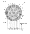
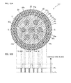
- FIG. 1A and 1B are a diagram illustrating a configuration of a multicore fiber 100 according to a first embodiment of the present invention. Specifically, FIG. 1A is a diagram illustrating a cross-sectional structure vertical to a longitudinal direction of the multicore fiber 100, and FIG. 1B is a diagram illustrating a refractive index distribution along a line B-B of the multicore fiber 100 illustrated in FIG. 1A .
- the multicore fiber 100 includes a cladding 40, a specific core element 10b disposed at the center in the radial direction of the cladding 40, three or more core elements 20a disposed in the cladding 40 so as to surround the core element 10b, an inner protective layer 41 that covers the circumferential surface of the cladding 40, and an outer protective layer 42 that covers the circumferential surface of the inner protective layer 41.
- FIG. 1A illustrates a case where one core element 10b is surrounded by six core elements 20a.
- the core element 10b includes a core 11, an inner cladding layer 12 that surrounds the circumferential surface of the core 11, and a low-refractive index layer 13b which surrounds the circumferential surface of the inner cladding layer 12 and of which the circumferential surface is surrounded by the cladding 40.
- the respective core elements 20a are disposed in the cladding 40 so that the centers thereof are arranged at equal intervals.
- the respective core elements 20a have the same structure as the core element 10b, and each include the same core 21 as the core 11, an inner cladding layer 22 that surrounds the circumferential surface of the core 21 and has the same structure as the inner cladding layer 12, and a low-refractive index layer 23a which surrounds the circumferential surface of the inner cladding layer 22 and of which the circumferential surface is surrounded by the cladding 40.
- the diameters of the respective cores 11 and 21 of the core elements 10b and 20a are the same
- the outer diameters of the respective inner cladding layers 12 and 22 are the same
- the outer diameters of the respective low-refractive index layers 13b and 23a are the same.
- the thicknesses of the respective inner cladding layers 12 and 22 are the same, and the thicknesses of the respective low-refractive index layers 13b and 23a are the same.
- the sizes of the respective members that constitute the multicore fiber 100 are not particularly limited, for example, the cores 11 and 21 have a diameter of 8.2 ⁇ m, the inner cladding layers 12 and 22 have an outer diameter of 19 ⁇ m, the low-refractive index layers 13b and 23a have an outer diameter of 27 ⁇ m, the cladding 40 has a diameter of 150 ⁇ m, the inner protective layer 41 has an outer diameter of 220 ⁇ m, and the outer protective layer 42 has an outer diameter of 270 ⁇ m.
- the respective cores 11 and 21 of the core elements 10b and 20a have the same refractive index (n 1 ), and the respective inner cladding layers 12 and 22 have the same refractive index (n 2 ).
- n 1 refractive index
- n 2 refractive index
- n 3a refractive index n 3b of the low-refractive index layer 13b of the core element 10b is higher than the refractive index n 3a of the low-refractive index layer 23a of the core element 20a.
- the plurality of core elements 10b and 20a can be classified into a partial core element 10b and the other partial core elements 20a.
- the refractive index n 2 of the inner cladding layers 12 and 22 and the refractive index n 4 of the cladding 40 are lower than the refractive index n 1 of the core 11, and the refractive indices n 3b and n 3a of the respective low-refractive index layers 13b and 23a are further lower than the refractive index n 2 of the inner cladding layers 12 and 22 and the refractive index n 4 of the cladding 40. That is, the respective refractive indices n 1 to n 4 satisfy the following relation: and
- the respective core elements 10b and 20a when the respective core elements 10b and 20a are seen from the perspective of the refractive index, since the low-refractive index layers 13b and 23a of the core elements 10b and 20a have a groove shape, the respective core elements 10b and 20a have a trench structure. With such a trench structure, it is possible to suppress bending loss of the multicore fiber 100. Moreover, since a mass production method for the optical fiber having a trench structure is well established, it is possible to easily manufacture the multicore fiber 100 at a low cost.
- the refractive indices of the respective low-refractive index layers 13b and 23a are uniform in the low-refractive index layers 13b and 23a, the refractive indices n 3b and n 3a of the low-refractive index layers 13b and 23a have the same meaning as an average refractive index.
- the cores 11 and 21 are formed, for example, of quartz in which impurities such as germanium that increases the refractive index are added, and the inner cladding layers 12 and 22 and the cladding 40 are formed of pure quartz in which no impurities are added.
- the low-refractive index layers 13b and 23a are formed of a material that has a lower refractive index than the cladding 40 and the inner cladding layers 12 and 22, for example, quartz in which impurities such as fluorine that decreases the refractive index are added, and the amounts of impurities added to the low-refractive index layer 13b and the low-refractive index layer 23a are different.
- the inner protective layer 41 and the outer protective layer 42 are formed of different types of ultraviolet-curable resins, for example.
- Propagation characteristics of an optical fiber are defined by a relative refractive index difference ⁇ to the refractive index of the cladding 40 based on the above refractive index.
- ⁇ i 1, 2, 3a, and 3b
- the refractive indices n 3b and n 3a of the low-refractive index layers 13b and 23a of the respective core elements 10b and 20a are lower than the refractive index n 2 of the inner cladding layer 12 and the refractive index n 4 of the cladding 40, the light confining effect in the core 11 increases, and light may not easily leak from the core 11. Thus, the light propagating through the core 11 can be prevented from leaking from the core elements 10b and 20a.
- the low-refractive index layers 13b and 23a having a low refractive index and the cladding 40 become barriers, and the crosstalk between the cores 11 and 21 of the adjacent core elements 10b and 20a or between the cores 21 of the adjacent core elements 20a can be suppressed.
- the relative refractive index difference of the cores 11 and 21 is defined by a mode field diameter MFD that a core should have as characteristics. Although in many cases, the relative refractive index difference of the inner cladding layers 12 and 22 to the cladding 40 is approximately zero as in the present embodiment, the relative refractive index difference is appropriately set to a positive or negative value for adjustment of wavelength dispersion characteristics.
- the refractive index n 2 of the inner cladding layers 12 and 22 is set to be between the refractive index n 1 of the cores 11 and 21 and the refractive index n 4 of the cladding 40, or is set to be between the refractive indices n 3a and n 3b of the low-refractive index layers 13b and 23a and the refractive index n 4 of the cladding 40.
- the refractive index n 3b of the low-refractive index layer 13b of the core element 10b is higher than the refractive index n 3a of the low-refractive index layer 23a of the core element 20a and satisfies a relation of n 3a ⁇ n 3b .
- the low-refractive index layer 13b of the specific core element 10b has larger light confinement loss in the core 11 than the low-refractive index layers 23a of the three or more core elements 20a that surround the specific core element 10b.
- the effect of the low-refractive index layer confining light in the own core is weaker than that in the core elements 20a that surround the specific core element 10b, and light can easily escape from the core element 10b.
- the specific core element 10b which is the partial core element light in high-order modes can easily escape than the core elements 20a which are the other partial core elements.
- Such a multicore fiber 100 is manufactured in the following manner. First, a specific core element glass member that becomes the core 11, the inner cladding layer 12, and the low-refractive index layer 13b and a plurality of core element glass members that become the core 21, the inner cladding layer 22, and the low-refractive index layer 23a are prepared. Further, these core element glass members are disposed in a cladding glass member that becomes the cladding 40 or a portion of the cladding 40 to allow the glass members to collapse, whereby a fiber base member of which the cross-sectional arrangement is similar to that of the multicore fiber 100 illustrated in FIG. 1A excluding the inner protective layer 41 and the outer protective layer 42 is manufactured.
- the manufactured fiber base member is heated, melted, and spun into a multicore fiber, and the multicore fiber is covered with the inner protective layer 41 and the outer protective layer 42 to obtain the multicore fiber 100.
- the core element glass member may be disposed in the cladding glass member that becomes the cladding 40 or a portion of the cladding 40 and spinning may be performed while allowing the glass members to collapse.
- the multicore fiber 100 includes the cladding 40 and the plurality of core elements 10b and 20a that are provided in the cladding 40 and include the cores 11 and 21, the inner cladding layers 12 and 22 that surround the cores 11 and 21, and the low-refractive index layers 13b and 23a that surround the inner cladding layers 12 and 22 and have a lower average refractive index than the cladding 40 and the inner cladding layers 12 and 22.
- the plurality of core elements are disposed so that the specific core element 10b is surrounded by three or more core elements 20a.
- the low-refractive index layer of a partial core element of the plurality of core elements has larger light confinement loss in the core than the low-refractive index layers of the other partial core elements.
- the partial core element is the specific core element 10b, and the other partial core elements are the three or more core elements 20a that surround the specific core element 10b.
- the multicore fiber includes a plurality of core elements in which the core is surrounded by a low-refractive index layer as in the core elements 10b and 20a of the present embodiment, and the specific core element is surrounded by three or more core elements, the cutoff wavelength of the specific core element tends to increase.
- the own low-refractive index layer 13b of the specific core element 10b has larger light confinement loss than the three or more core elements 20a that surround the specific core element 10b.
- the effect of the low-refractive index layer confining light in the own core is weaker than that in the three or more core elements 20a that surround the specific core element 10b, and light can easily escape from the core element 10b.
- the low-refractive index layers 23a of the core elements 20a that surround the core element 10b make the light in high-order modes difficult to escape from the specific core element 10b.
- the cutoff wavelength of the specific core element 10b can be suppressed from increasing as compared to that of the core elements 20a that surround the core element 10b. In this manner, it is possible to suppress the cutoff wavelength of the respective core elements 10b and 20a from changing and to suppress the conditions for performing single-mode communication in the respective core elements 10b and 20a from changing.
- the refractive index n 3b of the low-refractive index layer 13b of the specific core element 10b is higher than the refractive index n 3a of the three or more core elements 20a that surround the core element 10b, and the low-refractive index layer 13b of the core element 10b has higher light confinement loss in the core 11 than the low-refractive index layer 23a of the core element 20a.
- the respective core elements 10b and 20a can have the same size.
- the degree of freedom in design is improved.
- FIG. 2A and 2B The same or equivalent constituent elements as those of the first embodiment will be denoted by the same reference numerals unless otherwise particularly stated, and redundant description thereof will not be provided.
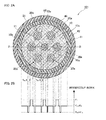
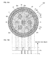
- FIG. 2A and 2B are a diagram illustrating a configuration of a multicore fiber 101 according to the second embodiment of the present invention. Specifically, FIG. 2A is a diagram illustrating a cross-sectional structure vertical to a longitudinal direction of the multicore fiber 101, and FIG. 2B is a diagram illustrating a refractive index distribution along a line B-B of the multicore fiber 101 illustrated in FIG. 2A .
- the multicore fiber 101 according to the present embodiment is different from the multicore fiber 100 according to the first embodiment, in that the multicore fiber 101 includes a specific core element 10c that is disposed at the same position as the core element 10b instead of the specific core element 10b according to the first embodiment.
- the specific core element 10c includes the same core 11 as the core 11 of the first embodiment, the same inner cladding layer 12 as the inner cladding layer 12 of the first embodiment, surrounding the circumferential surface of the core 11, and a low-refractive index layer 13c that surrounds the circumferential surface of the inner cladding layer 12.
- the refractive index n 3c of the low-refractive index layer 13c is the same as the refractive index n 3a of the respective low-refractive index layers 23a of the three or more core elements 20a that surround the specific core element 10c.
- the thickness t 3c of the low-refractive index layer 13c is smaller than the thickness t 3a of the low-refractive index layer 23a.
- the low-refractive index layer 13c of the specific core element 10c has larger light confinement loss in the core 11 than the low-refractive index layers 23a of the respective core elements 20a.
- the outer diameter of the core element 10c is smaller than the outer diameter of the core element 20a by an amount corresponding to the difference between the thickness of the low-refractive index layer 13c and the thickness of the low-refractive index layer 23a.
- the core elements 10c and 20a can be classified into the partial core element 10c and the other partial core elements 20a.
- Such a multicore fiber 101 may use the specific core element glass member that becomes the core 11, the inner cladding layer 12, and the low-refractive index layer 13c instead of the specific core element glass member that becomes the core 11, the inner cladding layer 12, and the low-refractive index layer 13b used in manufacturing of the multicore fiber 100.
- the low-refractive index layer 13c of the specific core element 10c since the low-refractive index layer 13c of the specific core element 10c is thinner than the low-refractive index layers 23a of the respective core elements 20a, the low-refractive index layer 13c of the core element 10c has larger light confinement loss in the core 11 than the low-refractive index layers 23a of the respective core elements 20a.
- the low-refractive index layer 13c makes the light in high-order modes easy to escape from the core 11, and the low-refractive index layers 23a of the respective core element 20a make the light in high-order modes difficult to escape.
- the cutoff wavelength of the core element 10c can be suppressed from increasing as compared to the core element 20a.
- the low-refractive index layer 13c of the specific core element 10c can be formed of the same material as the low-refractive index layers 23a of the respective core elements 20a.
- the degree of freedom in selecting the material of the low-refractive index layer is improved.
- FIG. 3A and 3B The same or equivalent constituent elements as those of the first embodiment will be denoted by the same reference numerals unless otherwise particularly stated, and redundant description thereof will not be provided.
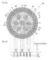
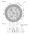
- FIG. 3A and 3B are a diagram illustrating a configuration of a multicore fiber 102 according to the third embodiment of the present invention. Specifically, FIG. 3A is a diagram illustrating a cross-sectional structure vertical to a longitudinal direction of the multicore fiber 102, and FIG. 3B is a diagram illustrating a refractive index distribution along a line B-B of the multicore fiber 102 illustrated in FIG. 3A .
- the multicore fiber 102 according to the present embodiment is different from the multicore fiber 100 according to the first embodiment, in that the multicore fiber 102 includes a specific core element 10e disposed at the same position as the core element 10b instead of the specific core element 10b of the first embodiment and includes three or more core elements 20d disposed at the same positions as the respective core elements 20a instead of the three or more core elements 20a of the first embodiment.
- the core elements 10e and 20d include the same cores 11 and 21 as the core 11 of the first embodiment and the same inner cladding layers 12 and 22 as the inner cladding layers 12 and 22 of the first embodiment, surrounding the circumferential surfaces of the cores 11 and 21.
- the core element 10e includes a low-refractive index layer 13e which surrounds the circumferential surface of the inner cladding layer 12 and of which the circumferential surface is surrounded by the cladding 40
- the core element 20d includes a low-refractive index layer 23d which surrounds the circumferential surface of the inner cladding layer 12 and of which the circumferential surface is surrounded by the cladding 40.
- Each of the low-refractive index layers 13e and 23d includes a plurality of low refractive index portions 5 that has a lower refractive index than the cladding 40 and the inner cladding layers 12 and 22 and surrounds the inner cladding layers 12 and 22.
- a plurality of circular holes are formed in the low-refractive index layers 13e and 23d, and the holes are the low refractive index portions 5.
- the low refractive index portion 5 has a circular cross-sectional shape.
- At least one of the plurality of low refractive index portions 5 of the respective core elements 10e and 20d is disposed on a straight line that connects the cores 11 and 21 of the own core elements and the cores 11 and 21 of the other core elements.
- a partial low refractive index portion 5 of the plurality of low refractive index portions 5 of the core element 10e is disposed on a straight line that connects the core 11 of the own core element 10e and the core 21 of the core element 20d.
- one low refractive index portion 5 of the plurality of low refractive index portions 5 is disposed on a straight line that connects the core 21 of the own core element 20d and the core 11 of the core element 10e, and at least another low refractive index portion 5 of the plurality of low refractive index portions 5 is disposed on a straight line that connects the core 21 of the own core element 20d and the core 21 of the other core element 20d.
- the low refractive index portion 5 is interposed between the own core and the other cores, it is possible to further suppress the inter-core crosstalk.
- the number of low refractive index portions 5 of the low-refractive index layer 13e of the specific core element 10e is smaller than the number of low refractive index portions 5 of the low-refractive index layer 23d of the core element 20d.
- the regions of the respective low-refractive index layers 13e and 23d other than the low refractive index portion 5 are formed of the same material as the cladding 40 and the inner cladding layer 12. Moreover, as illustrated in FIG.
- the refractive index n 5 of the low refractive index portion 5 is 1 and is lower than the refractive indices n 2 and n 4 of the inner cladding layers 12 and 22 and the cladding 40, the average refractive indices n 3e and n 3d of the low-refractive index layers 13e and 23d are lower than the inner cladding layer 12 and the cladding 40.
- the average refractive index n 3e of the low-refractive index layer 13e is higher than the average refractive index n 3d of the low-refractive index layer 23d.
- the low-refractive index layer 13e of the specific core element 10e has larger light confinement loss in the core 11 than the low-refractive index layers 23d of the respective core elements 20d.
- the core elements 10e and 20d when the respective core elements 10e and 20d are classified according to the cross-sectional structure of the core element and the average refractive index of the low-refractive index layer, the core elements 10e and 20d can be classified into the partial core element 10e and the other partial core elements 20d.
- Such a multicore fiber 102 is manufactured in the following manner.
- a specific core element glass member that becomes the core 11, the inner cladding layer 12, and the low-refractive index layer 13e, and a plurality of core element glass members that become the core 11, the inner cladding layer 12, and the low-refractive index layer 23d are prepared.
- the member that becomes the low-refractive index layers 13e and 23d is a glass tube that is disposed at the positions corresponding to the respective low refractive index portions so that the respective low refractive index portions (holes) are formed.
- These core element glass members are disposed in the cladding glass member that becomes the cladding 40 or a portion of the cladding 40 and are allowed to collapse with predetermined pressure applied to the penetration holes of the glass tubes, whereby a fiber base member of which the cross-sectional arrangement is similar to that of the multicore fiber 102 illustrated in FIG. 3A excluding the inner protective layer 41 and the outer protective layer 42 is manufactured.
- the manufactured fiber base member is heated, melted, and spun into a multicore fiber with predetermined pressure applied to the penetration holes, and the multicore fiber is covered with the inner protective layer 41 and the outer protective layer 42 to obtain the multicore fiber 102.
- the core element glass member may be disposed in the cladding glass member that becomes the cladding 40 or a portion of the cladding 40 and spinning may be performed with predetermined pressure applied to the penetration holes while allowing the glass members to collapse.
- the low refractive index portion 5 having a low refractive index is not formed continuously in a circular form so as to surround the respective cores 11 and 21, the light in high-order modes can appropriately escape from the respective cores 11 and 21. Thus, it is possible to suppress the cutoff wavelengths of the respective cores 11 from increasing.
- the low refractive index portion 5 is a hole
- the hole portion is manufactured using a glass tube
- the low refractive index portion 5 is not particular limited to a hole as long as the material of the low refractive index portion 5 has a lower refractive index than the inner cladding layer 12 and the cladding 40.
- the low refractive index portion 5 can be formed of quartz in which impurities such as fluorine that decreases the refractive index are added. Even in this case, according to the multicore fiber 102 of the present embodiment, since the amount of quartz in which expensive fluorine is added can be decreased, it is possible to manufacture the multicore fiber 102 at a low cost.
- FIG. 4A and 4B a fourth embodiment of the present invention will be described with reference to FIG. 4A and 4B .
- the same or equivalent constituent elements as those of the third embodiment will be denoted by the same reference numerals unless otherwise particularly stated, and redundant description thereof will not be provided.
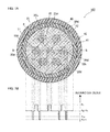
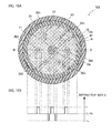
- FIG. 4A and 4B are a diagram illustrating a configuration of a multicore fiber 103 according to the fourth embodiment of the present invention. Specifically, FIG. 4A is a diagram illustrating a cross-sectional structure vertical to a longitudinal direction of the multicore fiber 103, and FIG. 4B is a diagram illustrating a refractive index distribution along a line B-B of the multicore fiber 103 illustrated in FIG. 4A .
- the multicore fiber 103 according to the present embodiment is different from the multicore fiber 102 according to the third embodiment, in that the multicore fiber 103 includes a specific core element 10f that is disposed at the same position as the core element 10e instead of the specific core element 10e according to the second embodiment.
- the core element 10f includes the same core 11 as the core 11 of the third embodiment and the same inner cladding layer 12 as the inner cladding layer 12 of the third embodiment, surrounding the circumferential surface of the core 11.
- the core element 10f includes a low-refractive index layer 13f which surrounds the circumferential surface of the inner cladding layer 12 and of which the circumferential surface is surrounded by the cladding 40.
- the low-refractive index layer 13f includes a plurality of low refractive index portions 5f which are formed as a hole having a circular cross-sectional shape. As described above, since the low refractive index portion 5 of the low-refractive index layer 23d is also formed as a hole, the refractive index n 5f of the low refractive index portion 5f of the low-refractive index layer 13f and the refractive index n 5 of the low refractive index portion 5 of the low-refractive index layer 23d of the core element 20d are the same and are 1.
- the number of low refractive index portions 5f of the low-refractive index layer 13f is the same as the number of low refractive index portions 5 of the low-refractive index layer 23d of the core element 20d, the area (the cross-sectional area vertical to the longitudinal direction) of each of the low refractive index portions 5f of the low-refractive index layer 13f is smaller than the area (the cross-sectional area vertical to the longitudinal direction) of each of the low refractive index portions 5 of the low-refractive index layer 23d.
- the regions of the low-refractive index layer 13f other than the low refractive index portion 5f are formed of the same material as the cladding 40 and the inner cladding layer 12.
- the average refractive index n 3f of the low-refractive index layer 13f of the core element 10f is higher than the average refractive index n 3d of the low-refractive index layer 23d of the core element 20d, and the thickness t 3f of the low-refractive index layer 13f of the core element 10f is smaller than the thickness t 3d of the low-refractive index layer 23d of the core element 20d.
- the low-refractive index layer 13f of the specific core element 10f has larger light confinement loss in the core 11 than the low-refractive index layers 23d of the respective core element 20d.
- the core elements 10f and 20d when the respective core elements 10f and 20d are classified according to the cross-sectional structure of the core element and the average refractive index of the low-refractive index layer, the core elements 10f and 20d can be classified into the partial core element 10f and the other partial core elements 20d.
- Such a multicore fiber 103 may use the specific core element glass member that becomes the core 11, the inner cladding layer 12, and the low-refractive index layer 13f instead of the specific core element glass member that becomes the core 11, the inner cladding layer 12, and the low-refractive index layer 13e used in manufacturing of the multicore fiber 102.
- the low refractive index portions 5 and 5f are not particular limited to a hole as long as the material of the low refractive index portions 5 and 5f has a lower refractive index than the inner cladding layer 12 and the cladding 40.
- the low refractive index portions 5 and 5f can be formed of quartz in which impurities such as fluorine that decreases the refractive index are added. In this case, according to the multicore fiber 103 of the present embodiment, since the amount of quartz in which fluorine used for the low refractive index 5f is added can be decreased, it is possible to manufacture the multicore fiber 103 at a low cost.
- FIG. 5A and 5B The same or equivalent constituent elements as those of the third embodiment will be denoted by the same reference numerals unless otherwise particularly stated, and redundant description thereof will not be provided.
- FIG. 5A and 5B are a diagram illustrating a configuration of a multicore fiber 104 according to the fifth embodiment of the present invention. Specifically, FIG. 5A is a diagram illustrating a cross-sectional structure vertical to a longitudinal direction of the multicore fiber 104, and FIG. 5B is a diagram illustrating a refractive index distribution along a line B-B of the multicore fiber 104 illustrated in FIG. 5A .
- the multicore fiber 104 according to the present embodiment is different from the multicore fiber 102 according to the third embodiment, in that the multicore fiber 104 includes a specific core element 10g that is disposed at the same position as the core element 10e instead of the specific core element 10e according to the second embodiment.
- the core element 10g includes the same core 11 as the core 11 of the third embodiment and the same inner cladding layer 12 as the inner cladding layer 12 of the third embodiment, surrounding the circumferential surface of the core 11. Moreover, the core element 10g includes a low-refractive index layer 13g which surrounds the circumferential surface of the inner cladding layer 12 and of which the circumferential surface is surrounded by the cladding 40.
- the low-refractive index layer 13g includes a plurality of low refractive index portions 5g.
- the respective low refractive index portions 5g are not holes but are formed of a material such as glass that has a lower refractive index n 5g than the refractive index n 4 of the cladding 40 and the refractive index n 2 of the inner cladding layer 12.
- Examples of the material of the low refractive index portion 5g having such a refractive index n 5g include the same material as the material of the low-refractive index layers 13b and 23a of the first embodiment.
- the number of low refractive index portions 5g of the low-refractive index layer 13g is the same as the number of low refractive index portions 5 of the low-refractive index layer 23d of the core element 20d, and the area (the cross-sectional area vertical to the longitudinal direction) of each of the low refractive index portions 5g is the same as the area (the cross-sectional area vertical to the longitudinal direction) of each of the low refractive index portions 5 of the low-refractive index layer 23d.
- the regions of the low-refractive index layer 13g other than the low refractive index portion 5g are formed of the same material as the cladding 40 and the inner cladding layer 12.
- the average refractive index n 3g of the low-refractive index layer 13g of the core element 10g is higher than the average refractive index n 3d of the low-refractive index layer 23d of the core element 20d.
- the low-refractive index layer 13g of the specific core element 10g has larger light confinement loss in the core 11 than the low-refractive index layer 23d of the core element 20d.
- the core elements 10g and 20d when the respective core elements 10g and 20d are classified according to the cross-sectional structure of the core element and the average refractive index of the low-refractive index layer, the core elements 10g and 20d can be classified into the partial core element 10g and the other partial core elements 20d.
- Such a multicore fiber 104 may use the specific core element glass member that becomes the core 11, the inner cladding layer 12, and the low-refractive index layer 13g instead of the specific core element glass member that becomes the core 11, the inner cladding layer 12, and the low-refractive index layer 13e used in manufacturing of the multicore fiber 102.
- the member that becomes the low-refractive index layer 13g may be a glass rod having a low refractive index that is disposed at the position corresponding to the low refractive index portion 5g.
- the respective core elements 10g and 20d can have the same size.
- the degree of freedom in design is improved.
- the low refractive index portion 5 is formed as a hole similarly to the third embodiment, the refractive index of the low refractive index portion 5 can be further decreased, the low refractive index portion 5 is not particular limited to a hole as long as the material of the low refractive index portion 5 has a lower refractive index than the inner cladding layer 12, the cladding 40, and the low refractive index portion 5g.
- FIG. 6A and 6B The same or equivalent constituent elements as those of the first embodiment will be denoted by the same reference numerals unless otherwise particularly stated, and redundant description thereof will not be provided.
- FIG. 6A and 6B are a diagram illustrating a configuration of a multicore fiber 105 according to the sixth embodiment of the present invention. Specifically, FIG. 6A is a diagram illustrating a cross-sectional structure vertical to a longitudinal direction of the multicore fiber 105, and FIG. 6B is a diagram illustrating a refractive index distribution along a line B-B of the multicore fiber 105 illustrated in FIG. 6A .
- the multicore fiber 105 according to the present embodiment is different from the multicore fiber 100 according to the first embodiment, in that the multicore fiber 105 includes a specific core element 10h that is disposed at the same position as the core element 10b instead of the specific core element 10b according to the first embodiment.
- the core element 10h includes the same core 11 as the core 11 of the first embodiment and the same inner cladding layer 12 as the inner cladding layer 12 of the first embodiment, surrounding the circumferential surface of the core 11 but does not include the low-refractive index layer of the core element 10b.
- the specific core element 10h does not have the light confining effect of the low-refractive index layer, and light is confined in the core 11 by the light confining effect of the core 11.
- the inner cladding layer 12 and the cladding 40 are formed of the same material, although there is no boundary between the inner cladding layer 12 and the cladding 40, an imaginary line that indicates the inner cladding layer 12 is depicted in FIG. 6A for better understanding.
- the core element 10h does not include the inner cladding layer 12 and the core 11 is directly disposed in the cladding 40.
- the refractive index of the low-refractive index layer 13b of the specific core element 10b which is the partial core element is increased up to the same refractive index as the cladding 40, whereby the specific core element 10b does not include the low-refractive index layer 13b, which is the same configuration as the core element 10h of the multicore fiber 105 according to the present embodiment.
- the multicore fiber 105 of the present embodiment has the same technical features as the multicore fiber 100 according to the first embodiment.
- the core elements 10h and 20a when the respective core elements 10h and 20a are classified according to the cross-sectional structure of the core element, the core elements 10h and 20a can be classified into the partial core element 10h and the other partial core elements 20a.
- Such a multicore fiber 105 includes the cladding 40 and the plurality of core elements 10h and 20a provided in the cladding 40.
- the plurality of core elements 10h and 20a are disposed so that the specific core element 10h is surrounded by three or more core elements 20a.
- the plurality of core elements 10h and 20a include the partial core element and the other partial core elements.
- the other partial core elements include the core 21, the inner cladding layer 22 that surrounds the core 21, and the low-refractive index layer 23a that surrounds the inner cladding layer 22 and has a lower average refractive index than the cladding 40 and the inner cladding layer 22.
- the partial core element includes the core 11 and does not include the low-refractive index layer, the partial core element is the specific core element 10h, and the other partial core elements are the three or more core elements 20a that surround the specific core element 10h.
- Such a multicore fiber 105 may use the specific core element glass member that becomes the core 11 and the inner cladding layer 12 instead of the specific core element glass member that becomes the core 11, the inner cladding layer 12, and the low-refractive index layer 13b used in manufacturing of the multicore fiber 100.
- the inner cladding layer 12 and the cladding 40 have the same refractive index, the inner cladding layer 12 and the cladding 40 can be formed of the same material.
- the portion that becomes the core element 10h may be the glass rod that becomes the core 11 and is inserted in a glass member that becomes the cladding.
- the multicore fiber 105 of the present embodiment since the cladding 40 and the low-refractive index layer 23a of the core element 20a are present between the core 11 of the specific core element 10h and the core 21 of each of the core elements 20a that surround the specific core element 10h, it is possible to reduce crosstalk. Moreover, since the specific core element 10h does not have the effect of confining light in the core due to the low-refractive index layer, the light in high-order modes can easily escape.
- the core element 10h it is possible to take a balance between the easiness of the light in high-order modes to escape due to the absence of the low-refractive index layer and the difficulty of the light in high-order modes to escape due to the low-refractive index layer 23a of each of the core elements 20a that surround the specific core element 10h. Thus, it is possible to prevent the cutoff wavelength of the specific core element 10h from increasing.
- the specific core element 10h does not have a low-refractive index layer and has a simple configuration, it is possible to provide the specific core element 10h easily.
- FIG. 7A and 7B The same or equivalent constituent elements as those of the third embodiment will be denoted by the same reference numerals unless otherwise particularly stated, and redundant description thereof will not be provided.
- FIG. 7A and 7B are a diagram illustrating a configuration of a multicore fiber 106 according to the seventh embodiment of the present invention. Specifically, FIG. 7A is a diagram illustrating a cross-sectional structure vertical to a longitudinal direction of the multicore fiber 106, and FIG. 7B is a diagram illustrating a refractive index distribution along a line B-B of the multicore fiber 106 illustrated in FIG. 7A .
- the multicore fiber 106 according to the present embodiment is different from the multicore fiber 102 according to the third embodiment, in that the multicore fiber 106 includes the specific core element 10h according to the sixth embodiment instead of the specific core element 10e according to the third embodiment.
- the core elements 10h and 20d when the respective core elements 10h and 20d are classified according to the cross-sectional structure of the core element and the average refractive index of the low-refractive index layer, the core elements 10h and 20d can be classified into the partial core element 10h and the other partial core elements 20d.
- At least one of the plurality of low refractive index portions 5 of the respective core elements 20d is disposed on a straight line that connects the core 21 of the own core element 20d and the cores 11 and 21 of the other core elements. That is, one low refractive index portion 5 of the plurality of low refractive index portions 5 in the respective core elements 20d is disposed on a straight line that connects the core 21 of the own core element 20d and the core 11 of the core element 10h, and at least another low refractive index portion 5 among the plurality of low refractive index portions 5 is disposed on a straight line that connects the core 21 of the own core element 20d and the core 21 of the other core element 20d. In this manner, since the low refractive index portion 5 is interposed between the own core 21 and the other cores 11 and 21, it is possible to further suppress the inter-core crosstalk.
- Such a multicore fiber 106 may use the specific core element glass member that becomes the core 11 and the inner cladding layer 12 according to the sixth embodiment instead of the specific core element glass member that becomes the core 11, the inner cladding layer 12, and the low-refractive index layer 13e used in manufacturing of the multicore fiber 102.
- the multicore fiber 106 similarly to the multicore fiber 105 according to the sixth embodiment, since the cladding 40 and the low-refractive index layer 23d of the core element 20d are present between the core 11 of the specific core element 10h and the cores 11 of the respective core elements 20d that surround the specific core element 10h, it is possible to reduce the crosstalk. Moreover, since the specific core element 10h does not have the effect of confining light in the core due to low-refractive index layer, the light in high-order modes can easily escape.
- the core element 10h it is possible to take a balance between the easiness of the light in high-order modes to escape due to the absence of the low-refractive index layer and the difficulty of the light in high-order modes to escape due to the low-refractive index layer 23d of each of the core elements 20d that surround the specific core element 10h. Thus, it is possible to prevent the cutoff wavelength of the specific core element 10h from increasing.
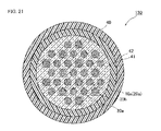
- FIG. 8 An eighth embodiment of the present invention will be described with reference to FIG. 8 .
- the same or equivalent constituent elements as those of the first embodiment will be denoted by the same reference numerals unless otherwise particularly stated, and redundant description thereof will not be provided.
- FIG. 8 is a diagram illustrating a cross-sectional structure vertical to a longitudinal direction of a multicore fiber 107 according to the eighth embodiment of the present invention.
- the multicore fiber 107 according to the present embodiment is different from the multicore fiber 100 according to the first embodiment, in that the number of three or more core elements 20a of the first embodiment is four or more, and the four or more core elements 20a are disposed so that the centers thereof form a rectangle.
- the arrangement of the plurality of core element glass members that become the core 21, the inner cladding layer 22, and the low-refractive index layer 23a used in manufacturing of the multicore fiber 100 may be the same as the arrangement of the respective core elements 20a of the multicore fiber 107 illustrated in FIG. 8 .
- the cores are disposed in a rectangular form, it is possible to easily take a matching with an optical device such as a planar waveguide and to easily input and output light to and from such an optical device.
- FIG. 9A and 9B The same or equivalent constituent elements as those of the first embodiment will be denoted by the same reference numerals unless otherwise particularly stated, and redundant description thereof will not be provided.
- FIG. 9A and 9B are a diagram illustrating a configuration of a multicore fiber 110 according to the ninth embodiment of the present invention. Specifically, FIG. 9A is a diagram illustrating a cross-sectional structure vertical to a longitudinal direction of the multicore fiber 110, and FIG. 9B is a diagram illustrating a refractive index distribution along a line B-B of the multicore fiber 110 illustrated in FIG. 9A .
- the multicore fiber 100 according to the present embodiment is different from the multicore fiber 100 according to the first embodiment, in that a plurality of core elements 10a, 20a, and 20b is disposed in the cladding.
- the specific core element 10a is disposed at the center of the cladding 40, and the three or more core elements that include the core element 20a and the core element 20b are disposed so as to surround the specific core element 10a.
- the number of three or more core elements that include the core elements 20a and 20b is an even number, the core elements 20a and the core elements 20b are alternately arranged, and the core elements 20a and the core elements 20b are arranged at equal intervals, respectively.
- FIG. 9A illustrates a case where one core element 10a is surrounded by six core elements that include the core elements 20a and 20b.
- the core element 10a includes the same core 11 as the core 11 of the core element 10b of the first embodiment, the same inner cladding layer 12 as the inner cladding layer 12 of the first embodiment, surrounding the circumferential surface of the core 11, and the low-refractive index layer 13a that surrounds the circumferential surface of the inner cladding layer 12. As illustrated in FIG.
- the low-refractive index layer 13a is different from the low-refractive index layer 13b of the first embodiment, in that the refractive index n 3a of the low-refractive index layer 13a is lower than the refractive index n 3b of the low-refractive index layer 13b of the core element 10b of the first embodiment and is the same as the low-refractive index layer 23a of the core element 20a.
- the other configuration thereof is the same as that of the low-refractive index layer 13b of the first embodiment.
- the core element 20b includes the same core 21 as the core 21 of the core element 20a, the same inner cladding layer 22 as the inner cladding layer 22 of the core element 20a, surrounding the circumferential surface of the core 21, and the low-refractive index layer 23b that surrounds the circumferential surface of the inner cladding layer 22.
- the low-refractive index layer 23b is different from the low-refractive index layer 23a of the core element 20a, in that the refractive index n 3b of the low-refractive index layer 23b is higher than the refractive index n 3a of the low-refractive index layer 23a of the core element 20a.
- the other configuration thereof is the same as that of the low-refractive index layer 23a of the core element 20a.
- the low-refractive index layer 23b of the core element 20b has larger light confinement loss in the core 21 than the low-refractive index layers 13a and 23a of the core elements 10a and 20a.
- the refractive index n 3a of the low-refractive index layer 13a of the core element 10a is the same as the refractive index of the low-refractive index layer 23a of the core element 20a. That is, although the core element 10a and the respective core elements 20a have the same structure, size, and refractive index, the core element 20b of the plurality of core elements has the same structure and size as (but a different refractive index from) the core elements 10a and 20a.
- the respective core elements 10a, 20a, and 20b are classified according to the refractive index, the plurality of core elements 10a, 20a, and 20b can be classified into the partial core element 20b and the other partial core elements 10a and 20a.
- such a multicore fiber 110 when the respective core elements 10a, 20a, and 20b are seen from the perspective of the refractive index, since the low-refractive index layers 13a, 23a, and 23b of the core elements 10a, 20a, and 20b have a rectangular shape, and the respective core elements 10a, 20a, and 20b have a trench structure, the effect of confining light in the core 11 increases, and light becomes difficult to leak from the core 11. Further, since the low-refractive index layers 13a, 23a, and 23b, and the cladding 40 having the low refractive index become barriers, it is possible to suppress the crosstalk between the cores 11 and 21 of the core elements 10a, 20a, and 20b.
- the bending loss of the multicore fiber 110 decreases. Further, since a mass production method for the optical fiber having the trench structure is well established, it is possible to easily manufacture the multicore fiber 110 at a low cost.
- the refractive indices of the respective low-refractive index layers 13a, 23a, and 23b are uniform in the low-refractive index layers 13a, 23a, and 23b, the refractive indices n 3a and n 3b of the low-refractive index layers 13a, 23a, and 23b have the same meaning as the average refractive index.
- the low-refractive index layer 13a of the core element 10a and the low-refractive index layer 23a of each of the core elements 20a have the same refractive index n 3a
- the refractive index n 3b of the low-refractive index layer 23b of the core element 20b is higher than the refractive index n 3a of the low-refractive index layers 13a and 23a of the core elements 10a and 20a and satisfies a relation of n 3a ⁇ n 3b .
- the low-refractive index layer 23b of the partial core element 20b classified in the above described manner has larger light confinement loss in the core 11 than the low-refractive index layers 13a and 23a of the other partial core elements 10a and 20a. That is, in the partial core element 20b, the effect of the low-refractive index layer confining light in the own core is weaker than the other partial core elements 10a and 20a, and light can easily escape from the core element 20b.
- the light confinement loss increases in the inside (a region including the regions between the core element 10a and the core elements 20a and 20b) of the entire core elements 20a and 20b that surround the specific core element 10a, and the light in high-order modes can easily escape from the vicinity of the partial core element 20b.
- Such a multicore fiber 110 is manufactured in the following manner. First, a specific core element glass member that becomes the core 11, the inner cladding layer 12, and the low-refractive index layer 13a, a plurality of core element glass members that becomes the core 21, the inner cladding layer 22, and the low-refractive index layer 23a, and a plurality of core element glass members that becomes the core 21, the inner cladding layer 22, and the low-refractive index layer 23b are prepared. Further, such a core element glass member is disposed in a cladding glass member that becomes the cladding 40 or a portion of the cladding 40 and is allowed to collapse, whereby a fiber base member of which the cross-sectional arrangement is similar to that of the multicore fiber 110 illustrated in FIG.
- the manufactured fiber base member is heated, melted, and spun into a multicore fiber, and the multicore fiber is covered with the inner protective layer 41 and the outer protective layer 42 to obtain the multicore fiber 110.
- the core element glass member may be disposed in the cladding glass member that becomes the cladding 40 or a portion of the cladding 40 and spinning may be performed while allowing the glass members to collapse.
- the multicore fiber 110 of the present embodiment in the vicinity of the partial core element 20b as described above, the light in high-order modes in the specific core element 10a can escape from the vicinity of the partial core element 20b.
- the cutoff wavelength of the specific core element 10a from increasing. In this manner, it is possible to suppress the cutoff wavelengths of the respective core elements 10a, 20a, and 20b from becoming different and to suppress the conditions for performing single-mode communication from becoming different in the respective core elements 10a, 20a, and 20b.
- the partial core element 20b and the other partial core elements 20a are alternately arranged as described above.
- locations where light can easily escape in regions surrounding the specific core element 10a can be arranged so as to be symmetrical about the specific core element 10a.
- the light in the specific core element 10a can be suppressed from being unevenly distributed in the radial direction of the core 11.
- partial core element 20b and the other partial core elements 20a are arranged alternately as described above, the partial core elements 20b may be arranged alternately.
- the low-refractive index layer 13b of the partial core element 20b has larger light confinement loss in the core 21 than the low-refractive index layer 13a and 23a of the other partial core elements 10a and 20a.
- the respective core elements 10a, 20a, and 20b can have the same size. Therefore, the degree of freedom in design is improved.
- FIG. 10A and 10B are a diagram illustrating a configuration of a multicore fiber 111 according to the tenth embodiment of the present invention. Specifically, FIG. 10A is a diagram illustrating a cross-sectional structure vertical to a longitudinal direction of the multicore fiber 111, and FIG. 10B is a diagram illustrating a refractive index distribution taken along a line B-B of the multicore fiber 111 illustrated in FIG. 10A .
- the multicore fiber 111 according to the present embodiment is different from the multicore fiber 110 according to the ninth embodiment, in that the multicore fiber 111 includes a core element 20c that is disposed at the same position as the core element 20b instead of the partial core element 20b of the ninth embodiment.
- the core element 20c includes the same core 21 as the core 21 of the ninth embodiment, the same inner cladding layer 22 as the inner cladding layer 22 of the ninth embodiment, surrounding the circumferential surface of the core 21, and a low-refractive index layer 23c that surrounds the circumferential surface of the inner cladding layer 22.
- the refractive index n 3c of the low-refractive index layer 23c is the same as the refractive index n 3a of the respective low-refractive index layers 13a and 23a of the specific core element 10a or the core elements 20a that surround the specific core element 10a.
- the thickness t 3c of the low-refractive index layer 23c is smaller than the thickness t 3a of the low-refractive index layers 13a and 23a.
- the low-refractive index layer 23c of the core element 20c has larger light confinement loss in the core 21 than the low-refractive index layers 13a and 23a of the core elements 10a and 20a.
- the outer diameter of the core element 20c is smaller than the outer diameter of the core elements 10a and 20a by an amount corresponding to the thickness t 3a of the low-refractive index layers 13a and 23a and the thickness t 3c of the low-refractive index layer 23c.
- Such a multicore fiber 111 may use the core element glass member that becomes the core 21, the inner cladding layer 22, and the low-refractive index layer 23c instead of the core element glass member that becomes the core 21, the inner cladding layer 22, and the low-refractive index layer 23b used in manufacturing of the multicore fiber 110.
- the low-refractive index layer 23c of the partial core element 20c is thinner than the low-refractive index layers 13a and 23a of the other partial core elements 10a and 20a, the low-refractive index layer 23c of the core element 20c has larger light confinement loss than the low-refractive index layers 13a and 23a of the core elements 10a and 20a.
- the light confinement loss of the specific core element 10a increases near the core element 20c having large light confinement loss, and the light in high-order modes propagating from the specific core element 10a can easily escape.
- the material of the low-refractive index layer 23c of the partial core element 20c can be formed of the same material as the low-refractive index layers 13a and 23a of the other partial core elements 10a and 20a.
- the degree of freedom in selecting the material of the low-refractive index layer is improved.
- FIG. 11A and 11B The same or equivalent constituent elements as those of the ninth embodiment will be denoted by the same reference numerals unless otherwise particularly stated, and redundant description thereof will not be provided.
- FIG. 11A and 11B are a diagram illustrating a configuration of a multicore fiber 112 according to the eleventh embodiment of the present invention. Specifically, FIG. 11A is a diagram illustrating a cross-sectional structure vertical to a longitudinal direction of the multicore fiber 112, and FIG. 11B is a diagram illustrating a refractive index distribution along a line B-B of the multicore fiber 112 illustrated in FIG. 11A .
- the multicore fiber 112 according to the present embodiment is different from the multicore fiber 110 according to the ninth embodiment, in that the multicore fiber 112 includes a specific core element 10d disposed at the same position as the core element 10a instead of the specific core element 10a of the ninth embodiment, core elements 20d disposed at the same positions as the respective core elements 20a instead of the core elements 20a of the ninth embodiment, and core elements 20e disposed at the same positions as the respective core elements 20b instead of the core elements 20b of the ninth embodiment.
- the specific core element 10d has the same structure as the respective core elements 20d.
- the respective core elements 10d and 20d have the same cores 11 and 21 as the cores 11 and 21 of the ninth embodiment and the same inner cladding layers 12 and 22 as the inner cladding layers 12 and 22 of the ninth embodiment, surrounding the circumferential surfaces of the cores 11 and 21.
- the core elements 10d and 20d include low-refractive index layers 13d and 23d which surround the circumferential surfaces of the inner cladding layers 12 and 22 and of which the circumferential surfaces are surrounded by the cladding 40.
- each of the core elements 20e includes the same core 21 as the core 21 of the ninth embodiment and the same inner cladding layer 22 as the inner cladding layer 22 of the ninth embodiment, surrounding the circumferential surface of the core 21.
- the core element 20e includes a low-refractive index layer 13e which surrounds the circumferential surface of the inner cladding layer 12 and of which the circumferential surface is surrounded by the cladding 40.
- Each of the low-refractive index layers 13d, 23d, and 23e includes a plurality of low refractive index portions 5 which has a lower refractive index than the cladding 40 and the inner cladding layer 12 and surrounds the inner cladding layer 12.
- a plurality of circular holes is formed in the low-refractive index layers 13d, 23d, and 23e, and the holes are the low refractive index portions 5.
- the low refractive index portion 5 has a circular cross-sectional shape.
- the number and the size of the low refractive index portions 5 provided in the low-refractive index layer 13d are the same as the number and the size of the low refractive index portions 5 provided in the low-refractive index layer 23d.
- the number of low refractive index portions 5 provided in the low-refractive index layer 23e of the core element 20e is smaller than the number of low refractive index portions 5 provided in each of the low-refractive index layers 13d and 23d, but the low refractive index portions 5 have the same size.
- At least one of the plurality of low refractive index portions 5 of each of the core elements 10d, 20d, and 20e is disposed on a straight line that connects the cores 11 and 21 of the own core element and the cores 11 and 21 of the other core elements.
- the low refractive index portion 5 of the core element 10d is disposed on a straight line that connects the core 11 of the own core element 10d and the cores 21 of the core elements 20d and 20e.
- one of the low refractive index portions 5 is disposed on a straight line that connects the core 21 of the own core element 20d and the core 11 of the core element 10d, and at least another one of the low refractive index portions 5 is disposed on a straight line that connects the core 21 of the own core element 20d and the core 21 of the other core element 20e. Further, in the core element 20e, one of the low refractive index portions 5 is disposed on a straight line that connects the core 21 of the own core element 20e and the core 11 of the core element 10d. In this manner, since the low refractive index portion 5 is interposed between the core of the own core element and the core of the other core element, it is possible to further suppress the inter-core crosstalk.
- the regions of the low-refractive index layers 13d, 23d, and 23e other than the low refractive index portion 5 are formed of the same material as the cladding 40 and the inner cladding layer 12. As illustrated in FIG. 11B , since the low refractive index portion 5 is a hole, and the refractive index n 5 of the low refractive index portion 5 is 1 and is lower than the refractive indices n 2 and n 4 of the inner cladding layer 12 and the cladding 40, the average refractive index n 3d of the low-refractive index layers 13d and 23d and the average refractive index n 3e of the low-refractive index layer 23e are lower than the inner cladding layer 12 and the cladding 40.
- the average refractive index n 3e of the low-refractive index layer 23e is higher than the average refractive index n 3d of the low-refractive index layers 13d and 23d.
- the core elements 10d, 20d, and 20e When the respective core elements 10d, 20d, and 20e are classified according to the cross-sectional structure of the core element and the average refractive index of the low-refractive index layer, the core elements 10d, 20d, and 20e can be classified into the partial core element 20e and the other partial core elements 10d and 20d.
- the average refractive index n 3e of the low-refractive index layer 23e is higher than the average refractive index n 3d of the low-refractive index layers 13d and 23d
- the low-refractive index layer 23e of the partial core element 20e has larger light confinement loss in the core 21 than the low-refractive index layers 13d and 23d of the other partial core elements 10d and 20d.
- Such a multicore fiber 112 is manufactured in the following manner.
- a specific core element glass member that becomes the core 11, the inner cladding layer 12, and the low-refractive index layer 13d, a plurality of core element glass members that becomes the core 21, the inner cladding layer 22, and the low-refractive index layer 23d, and a plurality of core element glass members that becomes the core 21, the inner cladding layer 22, and the low-refractive index layer 23e are prepared.
- the member that becomes the low-refractive index layers 13d, 23d, and 23e is a glass tube that is disposed at the positions corresponding to the respective low refractive index portions so that the respective low refractive index portions (holes) are formed.
- These core element glass members are disposed in the cladding glass member that becomes the cladding 40 or a portion of the cladding 40 and are allowed to collapse with predetermined pressure applied to the penetration holes of the glass tubes, whereby a fiber base member of which the cross-sectional arrangement is similar to that of the multicore fiber 112 illustrated in FIG. 11A excluding the inner protective layer 41 and the outer protective layer 42 is manufactured.
- the manufactured fiber base member is heated, melted, and spun into a multicore fiber with predetermined pressure applied to the penetration holes, and the multicore fiber is covered with the inner protective layer 41 and the outer protective layer 42 to obtain the multicore fiber 112.
- the core element glass member may be disposed in the cladding glass member that becomes the cladding 40 and a portion of the cladding 40 and spinning may be performed with predetermined pressure applied to the penetration holes while allowing the glass members to collapse.
- the low-refractive index layer 23e of the partial core element 20e has larger light confinement loss in the core 21 than the low-refractive index layers 13d and 23d of the other partial core elements 10d and 20d, it is possible to prevent the cutoff wavelength of the core 11 of the specific core element 10d from increasing.
- the low refractive index portion 5 having a low refractive index is not formed continuously in a circular form so as to surround the respective cores 11 and 21, the light in high-order modes can appropriately escape from the respective cores 11 and 21. Thus, it is possible to suppress the cutoff wavelengths of the respective cores 11 and 21 from increasing.
- the low refractive index portion 5 is a hole
- the hole portion is manufactured using a glass tube
- the low refractive index portion 5 is not particularly limited to a hole as long as the material of the low refractive index portion 5 has a lower refractive index than the inner cladding layer 12 and the cladding 40.
- the low refractive index portion 5 can be formed of quartz in which impurities such as fluoride that decreases the refractive index are added. In this case, according to the multicore fiber 112 of the present embodiment, since the amount of quartz in which expensive fluoride is added can be decreased, it is possible to manufacture the multicore fiber 112 at a low cost.
- FIG. 12A and 12B are a diagram illustrating a configuration of a multicore fiber 113 according to the twelfth embodiment of the present invention. Specifically, FIG. 12A is a diagram illustrating a cross-sectional structure vertical to a longitudinal direction of the multicore fiber 113, and FIG. 12B is a diagram illustrating a refractive index distribution taken along a line B-B of the multicore fiber 113 illustrated in FIG. 12A .
- the multicore fiber 113 according to the present embodiment is different from the multicore fiber 112 according to the eleventh embodiment, in that the multicore fiber 113 includes a core element 20f that is disposed at the same position as the core element 20e instead of the partial core element 20e according to the eleventh embodiment.
- the core element 20f includes the same core 21 as the core 21 of the partial core element 20e of the eleventh embodiment and the same inner cladding layer 22 as the inner cladding layer 22 of the core element 20e of the eleventh embodiment, surrounding the circumferential surface of the core 21.
- the core element 20f includes a low-refractive index layer 23f which surrounds the circumferential surface of the inner cladding layer 22 and of which the circumferential surface is surrounded by the cladding 40.
- the low-refractive index layer 23f includes a plurality of low refractive index portions 5f which is formed as a hole having a circular cross-sectional shape. As described above, since the low refractive index portions 5 of the low-refractive index layers 13d and 23d of the core elements 10d and 20d are also formed as a hole, the refractive index n 5f of the low refractive index portion 5f of the low-refractive index layer 23f and the refractive index n 5 of the low refractive index portions 5 of the low-refractive index layers 13d and 23d of the core elements 10d and 20d are the same and are 1.
- the number of low refractive index portions 5f of the low-refractive index layer 23f is the same as the number of low refractive index portions 5 of the low-refractive index layers 13d and 23d of the core elements 10d and 20d, the area (the cross-sectional area vertical to the longitudinal direction) of each of the low refractive index portions 5f of the low-refractive index layer 23f is smaller than the area (the cross-sectional area vertical to the longitudinal direction) of each of the low refractive index portions 5 of the low-refractive index layers 13d and 23d.
- the regions of the low-refractive index layer 23f other than the low refractive index portion 5f are formed of the same material as the cladding 40 and the inner cladding layer 12.
- the average refractive index n 3f of the low-refractive index layer 23f of the core element 20f is higher than the average refractive index n 3d of the low-refractive index layers 13d and 23d of the core elements 10d and 20d
- the thickness t 3f of the low-refractive index layer 23f of the core element 20f is smaller than the thickness t 3d of each of the low-refractive index layers 13d and 23d of the core elements 10d and 20d.
- the core elements 10d, 20d, and 20f are classified according to the cross-sectional structure of the core element and the refractive index, the core elements 10d, 20d, and 20f can be classified into the partial core element 20f and the other partial core elements 10d and 20d.
- the low-refractive index layer 23f of the partial core element 20f has larger light confinement loss in the core 21 than the low-refractive index layers 13d and 23d of the core elements 10d and 20d.
- Such a multicore fiber 113 may use the plurality of core element glass members that becomes the core 21, the inner cladding layer 22, and the low-refractive index layer 23f instead of the plurality of core element glass members that becomes the core 21, the inner cladding layer 22, and the low-refractive index layer 23e used in manufacturing of the multicore fiber 112 according to the tenth embodiment.
- the low refractive index portions 5 and 5f are formed as a hole similarly to the eleventh embodiment, the refractive index of the low refractive index portions 5 and 5f can be further decreased, the low refractive index portions 5 and 5f are not particularly limited to a hole as long as the material of the low refractive index portions 5 and 5f has a lower refractive index than the inner cladding layers 12 and 22 and the cladding 40.
- FIG. 13A and 13B The same or equivalent constituent elements as those of the eleventh embodiment will be denoted by the same reference numerals unless otherwise particularly stated, and redundant description thereof will not be provided.
- FIG. 13A and 13B are a diagram illustrating a configuration of a multicore fiber 114 according to the thirteenth embodiment of the present invention. Specifically, FIG. 13A is a diagram illustrating a cross-sectional structure vertical to a longitudinal direction of the multicore fiber 114, and FIG. 13B is a diagram illustrating a refractive index distribution taken along a line B-B of the multicore fiber 114 illustrated in FIG. 13A .
- the multicore fiber 114 according to the present embodiment is different from the multicore fiber 112 according to the eleventh embodiment, in that the multicore fiber 114 includes a core element 20g that is disposed at the same position as the core element 20e instead of the partial core element 20e according to the eleventh embodiment.
- the core element 20g includes the same core 21 as the core 21 of the core element 20e of the eleventh embodiment and the same inner cladding layer 22 as the inner cladding layer 22 of the eleventh embodiment, surrounding the circumferential surface of the core 21. Moreover, the core element 20g includes a low-refractive index layer 23g which surrounds the circumferential surface of the inner cladding layer 22 and of which the circumferential surface is surrounded by the cladding 40.
- the low-refractive index layer 23g includes a plurality of low refractive index portions 5g.
- the respective low refractive index portions 5g are not holes, but are formed of a material such as glass that has a lower refractive index n 5g than the refractive index n 4 of the cladding 40 and the refractive index n 2 of the inner cladding layer 12.
- Examples of the material of the low refractive index portion 5g having such a refractive index n 5g include the same material as the material of the low-refractive index layer 13a of the ninth embodiment.
- the number of low refractive index portions 5g of the low-refractive index layer 23g is the same as the number of low refractive index portions 5 of the low-refractive index layers 13d and 23d of the core elements 10d and 20d, and the area (the cross-sectional area vertical to the longitudinal direction) of each of the low refractive index portions 5g is the same as the area (the cross-sectional area vertical to the longitudinal direction) of each of the low refractive index portions 5 of the low-refractive index layers 13d and 23d.
- the regions of the low-refractive index layer 23g other than the low refractive index portion 5g are formed of the same material as the cladding 40 and the inner cladding layer 12.
- the low refractive index portion 5g is formed of a material such as glass, the low refractive index portion 5g has a higher refractive index than the low refractive index portion 5 formed as a hole.
- the average refractive index n 3g of the low-refractive index layer 23g of the core element 20g is higher than the average refractive index n 3d of the low-refractive index layers 13d and 23d of the core elements 10d and 20d.
- the core elements 10d, 20d, and 20g are classified according to the cross-sectional structure of the core element and the refractive index, the core elements 10d, 20d, and 20g can be classified into the partial core element 20g and the other partial core elements 10d and 20d.
- the low-refractive index layer 23g of the partial core element 20g has larger light confinement loss in the core 21 than the low-refractive index layers 13d and 23d of the other partial core elements 10d and 20d.
- Such a multicore fiber 113 may use a plurality of core element glass members that becomes the core 11, the inner cladding layer 12, and the low-refractive index layer 13g instead of the plurality of core element glass members that becomes the core 21, the inner cladding layer 22, and the low-refractive index layer 23e used in manufacturing of the multicore fiber 112 according to the tenth embodiment.
- the member that becomes the low-refractive index layer 13g may be a glass rod having a low refractive index that is disposed at the position corresponding to the low refractive index portion 5g.
- the respective core elements 10g and 10f can have the same size.
- the degree of freedom in design is improved.
- the low refractive index portion 5 is formed as a hole similarly to the eleventh embodiment, the refractive index of the low refractive index portion 5 can be further decreased, the low refractive index portion 5 is not particularly limited to a hole as long as the material of the low refractive index portion 5 has a lower refractive index than the inner cladding layer 12, the cladding 40, and the low refractive index portion 5g.
- FIG. 14A and 14B The same or equivalent constituent elements as those of the ninth embodiment will be denoted by the same reference numerals unless otherwise particularly stated, and redundant description thereof will not be provided.
- FIG. 14A and 14B are a diagram illustrating a configuration of a multicore fiber 115 according to the fourteenth embodiment of the present invention. Specifically, FIG. 14A is a diagram illustrating a cross-sectional structure vertical to a longitudinal direction of the multicore fiber 115, and FIG. 14B is a diagram illustrating a refractive index distribution taken along a line B-B of the multicore fiber 115 illustrated in FIG. 14A .
- the multicore fiber 115 according to the present embodiment is different from the multicore fiber 110 according to the ninth embodiment, in that all of the three or more core elements that surround the specific core element 10a are the core elements 20b.
- all of the core elements 20b that surround the specific core element 10a can be classified as the partial core element and the specific core element 10a can be classified as the other partial core element.
- Such a multicore fiber 115 may use a core element glass member that becomes the core 21, the inner cladding layer 22, and the low-refractive index layer 23b instead of the core element glass member that becomes the core 21, the inner cladding layer 22, and the low-refractive index layer 23a used in manufacturing of the multicore fiber 110 according to the ninth embodiment.
- the light in the high-order modes of the specific core element 10a can more easily escape from the vicinity of the respective core elements 20b of the three or more core elements 20b that surround the specific core element 10a.
- FIG. 15A and 15B The same or equivalent constituent elements as those of the eleventh embodiment will be denoted by the same reference numerals unless otherwise particularly stated, and redundant description thereof will not be provided.
- FIG. 15A and 15B are a diagram illustrating a configuration of a multicore fiber 116 according to the fifteenth embodiment of the present invention. Specifically, FIG. 15A is a diagram illustrating a cross-sectional structure vertical to a longitudinal direction of the multicore fiber 116, and FIG. 15B is a diagram illustrating a refractive index distribution along a line B-B of the multicore fiber 116 illustrated in FIG. 15A .
- the multicore fiber 116 according to the present embodiment is different from the multicore fiber 112 according to the eleventh embodiment, in that all of the three or more core elements that surround the specific core element 10d are the core elements 20e.
- all of the core elements 20e that surround the specific core element 10d can be classified as the partial core element and the specific core element 10d can be classified as the other partial core element.
- Such a multicore fiber 116 may use a core element glass member that becomes the core 21, the inner cladding layer 22, and the low-refractive index layer 23e instead of the core element glass member that becomes the core 21, the inner cladding layer 22, and the low-refractive index layer 23d used in manufacturing of the multicore fiber 112 according to the eleventh embodiment.
- the light in the high-order modes of the specific core element 10d can more easily escape from the vicinity of the respective core elements 20e of the three or more core elements 20e that surround the specific core element 10d.
- FIG. 16A and 16B The same or equivalent constituent elements as those of the ninth embodiment will be denoted by the same reference numerals unless otherwise particularly stated, and redundant description thereof will not be provided.
- FIG. 16A and 16B are a diagram illustrating a configuration of a multicore fiber 120 according to the sixteenth embodiment of the present invention. Specifically, FIG. 16A is a diagram illustrating a cross-sectional structure vertical to a longitudinal direction of the multicore fiber 120, and FIG. 16B is a diagram illustrating a refractive index distribution along a line B-B of the multicore fiber 120 illustrated in FIG. 16A .
- the multicore fiber 120 according to the present embodiment is different from the multicore fiber 110 according to the ninth embodiment, in that the multicore fiber 120 includes a core element 20h that is disposed at the same position as the core element 20b instead of the partial core element 20b according to the ninth embodiment.
- the core element 20h includes the same core 21 as the core 21 of the core element 20a and the same inner cladding layer 22 as the inner cladding layer 22 of the core element 20a, surrounding the circumferential surface of the core 21 but does not include the low-refractive index layer of the core element 20a.
- the core element 20h does not have the light confining effect of the low-refractive index layer, and light is confined in the core 21 by the light confining effect of the core 21 in the core element 20h.
- the inner cladding layer 22 and the cladding 40 are formed of the same material, although there is no boundary between the inner cladding layer 22 and the cladding 40, an imaginary line that indicates the inner cladding layer 22 is depicted in FIG. 16A for better understanding.
- the core element 20h does not include the inner cladding layer 22 and the core 21 is directly disposed in the cladding 40.
- the refractive index of the low-refractive index layer 23b of the core element 20b which is the partial core element is increased up to the same refractive index as the cladding 40, whereby the core element 20b does not include the low-refractive index layer 23b, which is the same configuration as the core element 20h of the multicore fiber 120 according to the present embodiment.
- the multicore fiber 120 of the present embodiment has the same technical features as the multicore fiber 110 according to the ninth embodiment.
- the core elements since the structure of the core element 20h is different from that of the other core elements 10a and 20a, when the respective core elements 10a, 20a, and 20h are classified according to the cross-sectional structure of the core element, the core elements can be classified into the partial core element 20h and the other partial core elements 10a and 20a.
- Such a multicore fiber 120 may use a core element glass member that becomes the core 21 and the inner cladding layer 22 instead of the core element glass member that becomes the core 21, the inner cladding layer 22, and the low-refractive index layer 23b used in manufacturing of the multicore fiber 110.
- the inner cladding layer 22 and the cladding 40 have the same refractive index as described above, the inner cladding layer 22 and the cladding 40 can be formed of the same material.
- the glass rod that becomes the core 21 is inserted in a glass member that becomes the cladding.
- the multicore fiber 120 of the present embodiment since the cladding 40 and the low-refractive index layers 13a and 23a of the core elements 10a and 20a are present between the core 21 of the partial core element 20h and the cores 11 and 21 of the other partial core elements 10a and 20a, it is possible to reduce crosstalk. Moreover, since the partial core element 20h does not have the effect of confining light in the core due to the low-refractive index layer, the light in high-order modes of the core element 10a can escape from the vicinity of the partial core element 20h. Thus, it is possible to prevent the cutoff wavelength of the specific core element 10a from increasing.
- the partial core element 20h does not have the low-refractive index layer and has a simple configuration, it is possible to provide the partial core element 20h easily.
- FIG. 17A and 17B The same or equivalent constituent elements as those of the eleventh embodiment will be denoted by the same reference numerals unless otherwise particularly stated, and redundant description thereof will not be provided.
- FIG. 17A and 17B are a diagram illustrating a configuration of a multicore fiber 121 according to the seventeenth embodiment of the present invention. Specifically, FIG. 17A is a diagram illustrating a cross-sectional structure vertical to a longitudinal direction of the multicore fiber 121, and FIG. 17B is a diagram illustrating a refractive index distribution along a line B-B of the multicore fiber 121 illustrated in FIG. 17A .
- the multicore fiber 121 according to the present embodiment is different from the multicore fiber 110 according to the eleventh embodiment, in that the same core element 20h as the core element 20h according to the sixteenth embodiment is disposed at the same position as the core element 20e instead of the partial core element 20e according to the eleventh embodiment.
- the core elements can be classified into the partial core element 20h and the other partial core elements 10d and 20d.
- Such a multicore fiber 121 may use a core element glass member that becomes the core 21 and the inner cladding layer 22 instead of the core element glass member that becomes the core 21, the inner cladding layer 22, and the low-refractive index layer 23e used in manufacturing of the multicore fiber 112.
- the inner cladding layer 22 and the cladding 40 can be formed of the same material similarly to the sixteenth embodiment. Thus, in the part that becomes the core element 20h, only the glass rod that becomes the core 21 is inserted in a glass member that becomes the cladding.
- the multicore fiber 121 of the present embodiment since the cladding 40 and the low-refractive index layers 13d and 23d of the core elements 10d and 20d are present between the core 21 of the partial core element 20h and the cores 11 and 21 of the other partial core elements 10d and 20d, it is possible to reduce crosstalk. Moreover, since the partial core element 20h does not have the effect of confining light in the core due to the low-refractive index layer, the light in high-order modes of the core element 10a can escape from the vicinity of the partial core element 20h. Thus, it is possible to prevent the cutoff wavelength of the specific core element 10d from increasing.
- the partial core element 20h does not have the low-refractive index layer and has a simple configuration, it is possible to provide the partial core element 20h easily.
- FIG. 18A and 18B The same or equivalent constituent elements as those of the sixteenth embodiment will be denoted by the same reference numerals unless otherwise particularly stated, and redundant description thereof will not be provided.
- FIG. 18A and 18B are a diagram illustrating a configuration of a multicore fiber 122 according to the eighteenth embodiment of the present invention. Specifically, FIG. 18A is a diagram illustrating a cross-sectional structure vertical to a longitudinal direction of the multicore fiber 122, and FIG. 18B is a diagram illustrating a refractive index distribution along a line B-B of the multicore fiber 122 illustrated in FIG. 18A .
- the multicore fiber 122 according to the present embodiment is different from the multicore fiber 110 according to the sixteenth embodiment, in that all of the three or more core elements that surround the specific core element 10a are the same core elements 20h as the core elements 20h of the sixteenth embodiment.
- all of the core elements 20h that surround the specific core element 10a do not have the effect of confining light due to the low-refractive index layer, and the core element 20h confines light in the core 21 just by the light confining effect of the core 21.
- all of the core elements 20h that surround the specific core element 10a can be classified as the partial core element, and the specific core element 10a can be classified as the other partial core element.
- Such a multicore fiber 122 may use a core element glass member that becomes the core 21 and the inner cladding layer 22 instead of the core element glass member that becomes the core 21, the inner cladding layer 22, and the low-refractive index layer 23a used in manufacturing of the multicore fiber 120.
- the inner cladding layer 22 and the cladding 40 can be formed of the same material similarly to the sixteenth embodiment. Thus, in the part that becomes the core element 20h, only the glass rod that becomes the core 21 is inserted in a glass member that becomes the cladding.
- the multicore fiber 122 of the present embodiment since the cladding 40 and the low-refractive index layer 13a of the core element 10a are present at least between the specific core element 10a and the core elements 20h that surround the core element 10a, it is possible to reduce crosstalk at least between the core element 10a and the core element 20h. Moreover, since the partial core element 20h does not have the effect of confining light in the core due to the low-refractive index layer, the light in high-order modes of the core element 10a can escape from the vicinity of the partial core element 20h. That is, according to the present embodiment, the light in high-order mode of the specific core element 10a can escape from the entire periphery of the specific core element 10a. Thus, it is possible to prevent the cutoff wavelength of the specific core element 10a from increasing.
- FIG. 19A and 19B The same or equivalent constituent elements as those of the seventeenth embodiment will be denoted by the same reference numerals unless otherwise particularly stated, and redundant description thereof will not be provided.
- FIG. 19 A and 19B are a diagram illustrating a configuration of a multicore fiber 123 according to the nineteenth embodiment of the present invention.
- FIG. 19A is a diagram illustrating a cross-sectional structure vertical to a longitudinal direction of the multicore fiber 123
- FIG. 19B is a diagram illustrating a refractive index distribution along a line B-B of the multicore fiber 123 illustrated in FIG. 19A .
- the multicore fiber 123 according to the present embodiment is different from the multicore fiber 110 according to the seventeenth embodiment, in that all of the three or more core elements that surround the specific core element 10d are the same core elements 20h as the core elements 20h of the seventeenth embodiment.
- all of the core elements 20h that surround the specific core element 10d do not have the effect of confining light due to the low-refractive index layer similarly to the multicore fiber 122 of the eighteenth embodiment, and the core element 20h confines light in the core 21 just by the light confining effect of the core 21.
- the core elements 20h that surround the specific core element 10d can be classified as the partial core element, and the specific core element 10d can be classified as the other partial core element.
- Such a multicore fiber 123 may use a core element glass member that becomes the partial core element 20h instead of the other partial core element 20d of the seventeenth embodiment.
- the inner cladding layer 22 and the cladding 40 can be formed of the same material similarly to the eighteenth embodiment. Thus, in the part that becomes the core element 20h, only the glass rod that becomes the core 21 is inserted in a glass member that becomes the cladding.
- the multicore fiber 122 of the present embodiment since the cladding 40 and the low-refractive index layer 13d of the core element 10d are present at least between the specific core element 10d and the core elements 20h that surround the core element 10d, it is possible to reduce crosstalk at least between the core element 10d and the core element 20h. Moreover, since the partial core element 20h does not have the effect of confining light in the core due to the low-refractive index layer, the light in high-order modes of the core element 10d can escape from the vicinity of the partial core element 20h. That is, according to the present embodiment, the light in high-order mode of the specific core element 10d can escape from the entire periphery of the specific core element 10d. Thus, it is possible to prevent the cutoff wavelength of the specific core element 10d from increasing.
- FIG. 20 a twentieth embodiment of the present invention will be specifically described with reference to FIG. 20 .
- the same or equivalent constituent elements as those of the ninth embodiment will be denoted by the same reference numerals unless otherwise particularly stated, and redundant description thereof will not be provided.
- FIG. 20 is a diagram illustrating a cross-sectional structure vertical to a longitudinal direction of a multicore fiber 117 according to the twentieth embodiment of the present invention.
- the multicore fiber 117 according to the present embodiment is different from the multicore fiber 100 according to the ninth embodiment, in that the number of three or more core elements that surround the specific core element 10a in the ninth embodiment is four or more, and the four or more core elements are disposed so that the centers thereof form a rectangle. Moreover, in the present embodiment, the core elements 20a are disposed at the apexes of the rectangle, and the core element 20b is disposed at each of the midpoints between the core elements 20a.
- the arrangement of the plurality of core element glass members that becomes the core 21, the inner cladding layer 22, and the low-refractive index layer 23a used in manufacturing of the multicore fiber 110 and the arrangement of the plurality of core element glass members that becomes the core 21, the inner cladding layer 22, and the low-refractive index layer 23b may be the same as the arrangement of the respective core elements 20a and 20b of the multicore fiber 117 illustrated in FIG 16A and 16B .
- the core elements 20a are disposed at the apexes of a rectangle, and the core element 20b is disposed at each of the midpoints between the core elements 20a, the core elements 20b may be disposed at the apexes of the rectangle, and the core element 20a may be disposed at each of the midpoints between the core elements 20b.
- the cores are disposed in a rectangular form, it is possible to easily take a matching with an optical device such as a planar waveguide and to easily input and output light to and from such an optical device.
- the arrangement and the number of core elements may be changed appropriately as long as the specific core element is surrounded by three or more core elements.
- FIG. 21 is a diagram illustrating a cross-sectional structure vertical to a longitudinal direction of a multicore fiber 130 according to a first modification of the present invention
- FIG. 22 is a diagram illustrating a cross-sectional structure vertical to a longitudinal direction of a multicore fiber 131 according to a second modification of the present invention
- FIG. 23 is a diagram illustrating a cross-sectional structure vertical to a longitudinal direction of a multicore fiber 132 according to a third modification of the present invention.
- the core elements 20b are surrounded by squares depicted by broken lines for better understanding.
- the core elements 20b surrounded by the broken-line squares have the same configuration as the core elements 20b of the ninth embodiment, and the other core elements are the same as the core elements 10a and 20a of the ninth embodiment.
- the core element 10 and the core element 20a have the same structure and refractive index.
- the plurality of core elements illustrated in FIGS. 21 to 23 is classified according to the refractive index, the plurality of core elements 10a, 20a, and 20b can be classified into the partial core element 20b and the other partial core elements 10a and 20a.
- the core element 10a of the ninth embodiment even when any one of the core elements surrounded by six core elements other than the core element 20b is the core element 10a of the ninth embodiment, at least one of the six core elements surrounding the core element 10a is the core element 20b.
- at least one of the three or more core elements that surround the core element 10a which is the specific core element is a core element that has large light confinement loss in the core of the low-refractive index layer. Therefore, high-order components of light can easily escape from the specific core element 10a.
- each of the plurality of core elements 10a is surrounded by six core elements 20b.
- each of the plurality of core elements 20b is surrounded by six core elements 20a, and it can be also understood that the plurality of core elements 10a is surrounded by three core elements 20a and three core elements 20b.
- the core elements 20b are the core elements 10b of the first embodiment, and each of the core elements 10b is surrounded by the core elements 20a.
- each of the plurality of specific core elements is surrounded by three or more core elements, and in the specific core element and the plurality of core elements that surround the specific core element, the low-refractive index layer of the partial core element has larger light confinement loss in the core than the low-refractive index layer of the other partial core elements.
- each of the plurality of specific core elements is the partial core element and has larger light confinement loss in the core than the other partial core elements that surround each of the specific core elements.
- the core element 10b of the eighth embodiment may be the core element 10c of the second embodiment
- the core element 10b of the eighth embodiment may be the core elements 10e, 10f, and 10g of the third to fifth embodiments
- the core element 20a of the eighth embodiment may be the core element 20d of the third embodiment
- the respective core elements 20a of the twentieth embodiment may be the core element 20d of the eleventh embodiment
- the respective core elements 20b of the twentieth embodiment may be the core element 20e of the eleventh embodiment
- the core element 10a may be the core element 10d of the eleventh embodiment.
- the core element 10a of the ninth embodiment may be the core element 10d of the eleventh embodiment, and alternatively, the core element 10d of the eleventh embodiment may be the core element 10a of the ninth embodiment. In this manner, the core elements of the respective embodiments may be appropriately combined with each other.
- the respective cores 11 and 21 have the same diameter, and the respective inner cladding layers 12 and 22 have the same outer diameter. Moreover, in the above embodiments, the respective low-refractive index layers have the same outer diameter.
- the present invention is not limited to this, and the diameters of the cores 11 and 21, the outer diameters of the inner cladding layers 12 and 22, and the outer diameters of the low-refractive index layers may be different in the respective core elements, and in particular, it is preferable that the cores 11 and 21 of the adjacent core elements have different diameters.
- the diameter of the core 21 of the three or more core elements that surround the specific core element disposed at the center may be different by approximately 1% from that of the core 11 of the central core element, and the diameter of the core 21 of the core elements on the outer circumference may be different by 1% to 2% from the diameter of the core 21 of the adjacent core elements.
- the diameters of the cores 11 and 21 of the respective core elements are physically slightly different from each other, the diameters of the respective cores 11 and 21 almost do not change, so that the light propagating through the cores 11 and 21 has approximately the same optical characteristics.
- the respective cores 11 and 21 of the respective core elements have the same refractive index n 1
- the inner cladding layers 12 and 22 have the same refractive index n 2
- the respective cores 11 and 21 of the respective core elements may have different refractive indices n 1
- the respective inner cladding layers 12 and 22 may have different refractive indices n 2
- the refractive index of the core 21 of the three or more core elements that surround the specific core element located at the center may be different by approximately 0.01% from that of the core 11 of the specific core element, and the refractive index of the core 21 of the three or more core elements that surround the specific core element may be different by 0.01% to 0.02% from the refractive index of the core 21 of the adjacent core elements.
- the refractive indices of the cores 11 and 21 of the respective core elements are physically slightly different from each other, the optical characteristic of the core 11 hardly have any difference from the optical characteristic of the core 21 in terms of the light propagating through the cores 11 and 21.
- a multicore fiber capable of suppressing the cutoff wavelength of a specific core from increasing while reducing inter-core crosstalk is provided. According to the multicore fiber of the present invention, it is possible to easily perform single-mode communication in a state where crosstalk is reduced.
Abstract
Description
- The present invention relates to a multicore fiber capable of suppressing the cutoff wavelength of a specific core from increasing while reducing crosstalk.
- Currently, an optical fiber used in an optical fiber communication system that is widely used has such a structure that the circumference of one core is surrounded by a cladding, and an optical signal propagates through the core, whereby information is transmitted. With the spread of the optical fiber communication system in recent years, the amount of transmitted information is increasing dramatically. With an increase in the amount of transmitted information, a large number of optical fibers ranging from several tens to several hundreds are used in the optical fiber communication system, to thereby enable large-volume and long-distance optical communication.
- In order to decrease the number of optical fibers used in such an optical fiber communication system, a technique of transmitting a plurality of signals via light that propagates through cores of a multicore fiber in which the circumferences of a plurality of cores are surrounded by one cladding is known.
- However, in the multicore fiber, inter-core crosstalk may occur. Thus, when the diameter of the multicore fiber decreases, since the inter-core distance decreases, the crosstalk occurs more easily. Thus, there is a demand for a multicore fiber that can reduce inter-core crosstalk.
-
Patent Document 1 described below discloses an example of a multicore fiber that can reduce such inter-core crosstalk. In this multicore fiber, a plurality of cores are disposed in the cladding, and a leakage reducing portion (low-refractive index layer) having a lower refractive index than the cladding is formed so as to surround the circumferential surface of each of the cores. Specifically, the circumferential surface of each of the cores is surrounded by an inner cladding layer having the same refractive index as the cladding, and the circumferential surface of each of the inner cladding layers is surrounded by the leakage reducing portion that has a lower refractive index than the cladding. -
- [Patent Document 1]
WO 2010/082656 A - With the configuration of
Patent Document 1 described above, the inter-core crosstalk can be reduced. However, as a result of studies, the present inventors have found that, in the multicore fiber disclosed inPatent Document 1, the cutoff wavelength of a specific core may increase due to the arrangement of cores, and it is not possible to perform single-mode communication in the specific core under the same conditions as the other cores. - Therefore, an object of the present invention is to provide a multicore fiber capable of suppressing the cutoff wavelength of a specific core from increasing while reducing inter-core crosstalk.
- The present inventors have intensively studied the causes of an increase in the cutoff wavelength of a specific core due to the arrangement of cores in a multicore fiber in which each core is surrounded by a low-refractive index layer. As a result, it was found that the phenomenon in which the cutoff wavelength increases occurs in a core that is located at a position where the core is surrounded by three or more cores. Thus, the present inventors have made a further progress in the studies and have reached the present invention.
- Namely, a multicore fiber of the present invention includes: a cladding; and a plurality of core elements provided in the cladding, including a core, an inner cladding layer that surrounds the core, and a low-refractive index layer that surrounds the inner cladding layer and has a lower average refractive index than the cladding and the inner cladding layer, wherein the plurality of core elements is arranged so as to surround a specific core element by three or more core elements, and a low-refractive index layer of a partial core element of the plurality of core elements has larger light confinement loss in the core than low-refractive index layers of the other partial core elements.
- According to such a multicore fiber, since each core is surrounded by a low-refractive index layer with an inner cladding layer interposed therebetween, the light confinement effect in each core is large, and light is unlikely to leak from the core. Thus, it is possible to reduce the inter-core crosstalk.
- As described above, the present inventors have discovered such a tendency that, in a specific core element surrounded by three or more core elements, the cutoff wavelength thereof is longer than the other core elements (that is, the three or more core elements). The present inventors have thought that this results from the fact that, when the respective core elements have the same conditions, since light is confined by the own low-refractive index layer of the specific core element, and light is confined by the low-refractive index layers of a plurality of core elements that surround the specific core element, the own low-refractive index layer and the low-refractive index layers of the plurality of core elements that surround the specific core make light in high-order modes difficult to escape. However, according to a multicore fiber of the present invention, the own low-refractive index layer of a partial core element has larger light confinement loss than the other partial core elements. That is, in the partial core element, the effect of the low-refractive index layer confining light in the own core is weaker than that in the other partial core elements, and light can easily escape from the core element. Thus, in the partial core element, light in high-order modes can easily escape. This is because the intensity on the outer side in the radial direction of a core element is stronger in the fundamental mode than in the high-order modes. Thus, when the partial core element is the specific core element, in the specific core element, it is possible to take a balance between the easiness of the light in high-order modes to escape due to the large light confinement loss in the own core and the difficulty of the light in high-order modes to escape due to the low-refractive index layers of the other partial core elements that surround the specific core element. Thus, it is possible to suppress the cutoff wavelength of the specific core element from increasing. Further, when the light confinement loss is increased by the own low-refractive index layer, the light confining force near the low-refractive index layer weakens. Thus, when the partial core element is at least one of the three or more core elements that surround the specific core element, the light confinement loss in the specific core element increases near the core element having the large light confinement loss, and the light in high-order modes propagating from the specific core element can easily escape. Therefore, it is possible to suppress the cutoff wavelength of the specific core element from increasing. In this manner, according to the present invention, by increasing the light confinement loss in the core by the low-refractive index layer of the partial core element among the plurality of core elements, it is possible to suppress the cutoff wavelength of the specific core element from increasing. Thus, it is possible to suppress the cutoff wavelengths of the respective core elements from becoming different and to suppress the conditions for performing single-mode communication from becoming different in the respective core elements.
- The low-refractive index layer may be formed of a material having a lower refractive index than the cladding and the inner cladding layer.
- When the respective core elements are seen from the perspective of the refractive indices, since the low-refractive index layer has a groove shape, the refractive index of the low-refractive index layer is called a trench structure. With such a structure, it is possible to suppress bending loss of the fiber. Moreover, since a mass production method is well established, it is possible to easily manufacture the fiber at a low cost.
- In this case, the low-refractive index layer of the partial core element may have a higher refractive index than the low-refractive index layers of the other partial core elements.
- With such a configuration, the low-refractive index layer of the partial core element has larger light confinement loss in the core than the low-refractive index layers of the other partial core elements. Such a configuration can be realized just by changing the material of the low-refractive index layer of the partial core element with the material of the low-refractive index layers of the other partial core elements, and the respective core elements can have the same size. Thus, the degree of freedom in design is improved.
- The low-refractive index layer of the partial core element may be thinner than the low-refractive index layers of the other partial core elements.
- With such a configuration, the low-refractive index layer of the partial core element has larger light confinement loss in the core than the low-refractive index layers of the other partial core elements, and the low-refractive index layer of the partial core element can be formed of the same material as that of the low-refractive index layers of the other partial core elements. Thus, the degree of freedom in selecting the material of the low-refractive index layer is improved.
- The low-refractive index layer may include a plurality of low refractive index portions which have a lower refractive index than the cladding and the inner cladding layer and surround the inner cladding layer.
- Since the low refractive index portion of the low-refractive index layer is not formed continuously in a circular form so as to surround the core, it is possible to increase the high-order mode light confinement loss in the respective cores and to suppress the cutoff wavelengths of the respective cores from increasing.
- In this case, the number of low refractive index portions of the partial core element may be smaller than the number of low refractive index portions of the other partial core elements.
- With this configuration, the low-refractive index layer of the partial core element has larger light confinement loss in the core than the low-refractive index layers of the other partial core elements. Further, by decreasing the number of low refractive index portions of the partial core element, it is possible to decrease man-hours forming the low refractive index portion and to form the low-refractive index layer of the specific core element more easily. With such a structure, when the low refractive index portion is a glass in which impurities such as fluorine that reduce the refractive index are contained, since the number of expensive glass can be reduced, it is possible to manufacture the multicore fiber at a low cost. Further, if the low refractive index portion is a hole, when a hole is formed in the fiber base member of the multicore fiber by drilling, it is possible to reduce the drilling cost. When a hole is formed in the fiber base member using a glass tube, it is possible to decrease the number of glass tubes and to reduce the cost.
- The low refractive index portion of the partial core element may have a smaller cross-sectional area than the low refractive index portions of the other partial core elements.
- With such a configuration, the low-refractive index layer of the partial core element has larger light confinement loss in the core than the low-refractive index layers of the other partial core elements. For example, when the low refractive index portion is formed of quartz in which impurities such as fluorine that decreases the refractive index are added, since the amount of fluorine-contained quartz used for the low refractive index portion can be reduced, it is possible to manufacture the multicore fiber at a low cost.
- The low refractive index portions may be holes. In this case, the refractive index of the low-refractive index layer can be further decreased, and the crosstalk can be further reduced.
- The low refractive index portion of the partial core element may have a higher refractive index than the low refractive index portions of the other partial core elements.
- With such a configuration, the respective core elements can have the same size just by changing the material of the low refractive index portion of the partial core element with the material of the low refractive index portions of the other partial core elements. Thus, the degree of freedom in design is improved.
- In this case, the low refractive index portions of the other partial core elements may be holes.
- Further, at least one of the low refractive index portions may be disposed on a straight line that connects the core of the own core element and the cores of the other core elements.
- With such a configuration, the low refractive index portion is interposed between cores, and the inter-core crosstalk can be further suppressed.
- Alternatively, the multicore fiber according to the present invention includes a cladding and a plurality of core elements provided in the cladding. The plurality of core elements include a partial core element and the other partial core elements and is arranged such that a specific core element is surrounded by three or more core elements, the other partial core elements include a core, an inner cladding layer that surrounds the core, and a low-refractive index layer that surrounds the inner cladding layer and has a lower average refractive index than the cladding and the inner cladding layer. The partial core element has a core and does not have the low-refractive index layer.
- In the multicore fiber in which each of the plurality of core elements has a low-refractive index layer, by increasing the refractive index of the low-refractive index layer of the partial core element up to the same refractive index as the cladding, a structure in which the partial core element does not have a low-refractive index layer is realized. With such a structure in which the partial core element does not have a low-refractive index layer, the partial core element has large light confinement loss in the core. Thus, such a multicore fiber has the same technical feature as the multicore fiber in which each of the plurality of core elements has the low-refractive index layer. When the partial core element does not have a low-refractive index layer, the partial core element does not have the light confining effect provided by the low-refractive index layer, and light is confined in the core by the light confining effect provided by the core. In the multicore fiber having such a configuration, at least the cladding and the low-refractive index layer of the core element that surrounds the specific core are present between the partial core element and the other partial core elements. Thus, it is possible to reduce the crosstalk at least between the partial core element and the other partial core elements and between the other partial core elements.
- Moreover, when the partial core element is the specific core element, since the effect of confining light in the own core of the specific core element is obtained by the core only, it is possible to take a balance between the easiness of the light in high-order modes to escape due to the large light confinement loss of the specific core element and the difficulty of the light in high-order modes to escape due to the low-refractive index layers of the other partial core elements that surround the specific core element. Thus, it is possible to prevent the cutoff wavelength of the specific core element from increasing. Moreover, when the partial core element is at least one of the three or more core elements that surround the specific core element, the light in high-order modes can easily escape from the vicinity of the core element. Thus, it is possible to suppress the cutoff wavelength of the specific core element from increasing. In this manner, even when the partial core element does not have the low-refractive index layer, it is possible to suppress the cutoff wavelength of the specific core element from increasing. Thus, it is possible to suppress the cutoff wavelengths of the respective core elements from becoming different and to suppress the conditions for performing single-mode communication from becoming different in the respective core elements.
- Further, since the partial core element does not have the low-refractive index layer and has a simple configuration, it is possible to easily form the partial core element.
- In this case, the low-refractive index layer may be formed of a material having a lower refractive index than the cladding and the inner cladding layer.
- With such a structure, it is possible to suppress bending loss of the fiber in the other partial core elements and to easily manufacture the fiber at a low cost because a mass production method is well established.
- Alternatively, the low-refractive index layer may include a plurality of low refractive index portions that have a lower refractive index than the cladding and the inner cladding layer and surround the inner cladding layer.
- According to such a structure, since the low refractive index portion having a low refractive index is not formed continuously in a circular form so as to surround the core, it is possible to increase the high-order mode light confinement loss in the other partial core elements and to suppress the cutoff wavelengths of the cores of the other partial core elements from increasing.
- In this case, the low refractive index portions may be holes. In this case, the refractive index of the low-refractive index layer can be further decreased, and the crosstalk can be further reduced.
- At least one of the low refractive index portions may be disposed on a straight line that connects the core of the own core element and the cores of the other core elements. In this case, the low refractive index portion interposed between cores further suppresses the inter-core crosstalk.
- In any one of the multicore fibers described above, the partial core element may be the specific core element.
- According to the multicore fiber having such a configuration, the own low-refractive index layer of the specific core element has larger light confinement loss than the three or more core elements that surround the specific core element. That is, in the specific core element, the effect of confining light in the own core is weaker than that in the three or more core elements that surround the specific core element, and light can easily escape from the core element. Thus, in the specific core element, the light in high-order modes of which the intensity on the outer side in the radial direction is stronger than that of the fundamental mode can easily escape. In this manner, it is possible to take a balance between the easiness of the light in high-order modes of the specific core element to escape and the difficulty of the light in high-order modes to escape due to the low-refractive index layers of the respective core elements that surround the specific core element. Thus, it is possible to prevent the cutoff wavelength of the specific core element from increasing. Thus, it is possible to suppress the cutoff wavelengths of the respective core elements from becoming different and to suppress the conditions for performing single-mode communication from becoming different in the respective core elements.
- Alternatively, in any one of the multicore fibers described above, the partial core element may be at least one of the three or more core elements that surround the specific core element.
- In such a case, as described above, the light confinement loss between the partial core elements and between the partial core element and the other partial core elements is larger than that between the other partial core elements, and light can easily escape from such positions. Thus, since the partial core element is at least one of the three or more core elements that surround the specific core element, the light in high-order modes of the specific core element can escape from between the partial core elements and between the partial core element and the other partial core elements. Thus, it is possible to prevent the cutoff wavelength of the specific core element from increasing. Thus, it is possible to suppress the cutoff wavelengths of the respective core elements from becoming different and to suppress the conditions for performing single-mode communication from becoming different in the respective core elements.
- Further, the partial core element may include all of the three or more core elements that surround the specific core element.
- In this case, it is possible to allow the light in high-order modes of the specific core element to more easily escape from the vicinity of each of the three or more core elements that surround the specific core element while suppressing the crosstalk between the specific core element and the three or more core elements. Thus, it is possible to suppress the cutoff wavelengths of the respective core elements from becoming different.
- Alternatively, the partial core element and the other partial core element may be alternately arranged in the three or more core elements that surround the specific core element.
- In this case, the locations where light can easily escape in regions between the three or more core elements that surround the specific core element can be arranged so as to be symmetrical about the specific core element while suppressing the crosstalk between three or more core elements. Thus, the light in the specific core element can be suppressed from being unevenly distributed in the radial direction of the core.
- The three or more core elements that surround the specific core element may be arranged such that the centers of the core elements are arranged at equal intervals.
- Alternatively, the three or more core elements that surround the specific core element may be arranged such that the centers of four or more core elements form a rectangle.
- As described above, according to the present invention, a multicore fiber capable of suppressing the cutoff wavelength of a specific core from increasing while reducing inter-core crosstalk is provided.
-
-
FIG. 1A and 1B are a diagram illustrating a configuration of a multicore fiber according to a first embodiment of the present invention. -
FIG. 2A and 2B are a diagram illustrating a configuration of a multicore fiber according to a second embodiment of the present invention. -
FIG. 3A and 3B are a diagram illustrating a configuration of a multicore fiber according to a third embodiment of the present invention. -
FIG. 4A and 4B are a diagram illustrating a configuration of a multicore fiber according to a fourth embodiment of the present invention. -
FIG. 5A and 5B are a diagram illustrating a configuration of a multicore fiber according to a fifth embodiment of the present invention. -
FIG. 6A and 6B are a diagram illustrating a configuration of a multicore fiber according to a sixth embodiment of the present invention. -
FIG. 7A and 7B are a diagram illustrating a configuration of a multicore fiber according to a seventh embodiment of the present invention. -
FIG. 8 is a diagram illustrating a cross-sectional structure vertical to a longitudinal direction of a multicore fiber according to an eighth embodiment of the present invention. -
FIG. 9A and 9B are a diagram illustrating a configuration of a multicore fiber according to a ninth embodiment of the present invention. -
FIG. 10A and 10B are a diagram illustrating a configuration of a multicore fiber according to a tenth embodiment of the present invention. -
FIG. 11A and 11B are a diagram illustrating a configuration of a multicore fiber according to an eleventh embodiment of the present invention. -
FIG. 12A and 12B are a diagram illustrating a configuration of a multicore fiber according to a twelfth embodiment of the present invention. -
FIG. 13A and 13B are a diagram illustrating a configuration of a multicore fiber according to a thirteenth embodiment of the present invention. -
FIG. 14A and 14B are a diagram illustrating a configuration of a multicore fiber according to a fourteenth embodiment of the present invention. -
FIG. 15A and 15B are a diagram illustrating a configuration of a multicore fiber according to a fifteenth embodiment of the present invention. -
FIG. 16A and 16B are a diagram illustrating a configuration of a multicore fiber according to a sixteenth embodiment of the present invention. -
FIG. 17A and 17B are a diagram illustrating a configuration of a multicore fiber according to a seventeenth embodiment of the present invention. -
FIG. 18A and 18B are a diagram illustrating a configuration of a multicore fiber according to an eighteenth embodiment of the present invention. -
FIG. 19A and 19B are a diagram illustrating a configuration of a multicore fiber according to a nineteenth embodiment of the present invention. -
FIG. 20 is a diagram illustrating a cross-sectional structure vertical to a longitudinal direction of a multicore fiber according to a twentieth embodiment of the present invention. -
FIG. 21 is a diagram illustrating a cross-sectional structure vertical to a longitudinal direction of a multicore fiber according to a first modification of the present invention. -
FIG. 22 is a diagram illustrating a cross-sectional structure vertical to a longitudinal direction of a multicore fiber according to a second modification of the present invention. -
FIG. 23 is a diagram illustrating a cross-sectional structure vertical to a longitudinal direction of a multicore fiber according to a third modification of the present invention. - Hereinafter, preferred embodiments of the multicore fiber according to the present invention will be described in detail with reference to the drawings.
-
FIG. 1A and 1B are a diagram illustrating a configuration of amulticore fiber 100 according to a first embodiment of the present invention. Specifically,FIG. 1A is a diagram illustrating a cross-sectional structure vertical to a longitudinal direction of themulticore fiber 100, andFIG. 1B is a diagram illustrating a refractive index distribution along a line B-B of themulticore fiber 100 illustrated inFIG. 1A . - As illustrated in
FIG. 1A , themulticore fiber 100 according to the present embodiment includes acladding 40, aspecific core element 10b disposed at the center in the radial direction of thecladding 40, three ormore core elements 20a disposed in thecladding 40 so as to surround thecore element 10b, an innerprotective layer 41 that covers the circumferential surface of thecladding 40, and an outerprotective layer 42 that covers the circumferential surface of the innerprotective layer 41.FIG. 1A illustrates a case where onecore element 10b is surrounded by sixcore elements 20a. - The
core element 10b includes a core 11, aninner cladding layer 12 that surrounds the circumferential surface of the core 11, and a low-refractive index layer 13b which surrounds the circumferential surface of theinner cladding layer 12 and of which the circumferential surface is surrounded by thecladding 40. Therespective core elements 20a are disposed in thecladding 40 so that the centers thereof are arranged at equal intervals. Moreover, therespective core elements 20a have the same structure as thecore element 10b, and each include thesame core 21 as thecore 11, aninner cladding layer 22 that surrounds the circumferential surface of thecore 21 and has the same structure as theinner cladding layer 12, and a low-refractive index layer 23a which surrounds the circumferential surface of theinner cladding layer 22 and of which the circumferential surface is surrounded by thecladding 40. In the present embodiment, the diameters of therespective cores core elements multicore fiber 100 are not particularly limited, for example, thecores cladding 40 has a diameter of 150 µm, the innerprotective layer 41 has an outer diameter of 220 µm, and the outerprotective layer 42 has an outer diameter of 270 µm. - In the present embodiment, the
respective cores core elements FIG. 1A and 1B , although the low-refractive index layers 23a of thecore elements 20a have the same refractive index (n3a), a refractive index n3b of the low-refractive index layer 13b of thecore element 10b is higher than the refractive index n3a of the low-refractive index layer 23a of thecore element 20a. Here, when thecore elements core elements partial core element 10b and the other partialcore elements 20a. - As illustrated in
FIG. 1B , the refractive index n2 of the inner cladding layers 12 and 22 and the refractive index n4 of thecladding 40 are lower than the refractive index n1 of the core 11, and the refractive indices n3b and n3a of the respective low-refractive index layers 13b and 23a are further lower than the refractive index n2 of the inner cladding layers 12 and 22 and the refractive index n4 of thecladding 40. That is, the respective refractive indices n1 to n4 satisfy the following relation:
 and
and

- In the present embodiment, the refractive index n2 of the
inner cladding layer 12 is the same as the refractive index n4 of thecladding 40. That is, n2 = n4. - In this manner, when the respective
core elements core elements core elements multicore fiber 100. Moreover, since a mass production method for the optical fiber having a trench structure is well established, it is possible to easily manufacture themulticore fiber 100 at a low cost. In the present embodiment, since the refractive indices of the respective low-refractive index layers 13b and 23a are uniform in the low-refractive index layers 13b and 23a, the refractive indices n3b and n3a of the low-refractive index layers 13b and 23a have the same meaning as an average refractive index. - In order for the
multicore fiber 100 to have such a refractive index, thecores cladding 40 are formed of pure quartz in which no impurities are added. Further, the low-refractive index layers 13b and 23a are formed of a material that has a lower refractive index than thecladding 40 and the inner cladding layers 12 and 22, for example, quartz in which impurities such as fluorine that decreases the refractive index are added, and the amounts of impurities added to the low-refractive index layer 13b and the low-refractive index layer 23a are different. Moreover, the innerprotective layer 41 and the outerprotective layer 42 are formed of different types of ultraviolet-curable resins, for example. - Propagation characteristics of an optical fiber are defined by a relative refractive index difference Δ to the refractive index of the
cladding 40 based on the above refractive index. When i = 1, 2, 3a, and 3b, the relative refractive index difference Δi of a layer having a refractive index of ni to thecladding 40 is defined by the following expression.
- In the
multicore fiber 100, since the refractive indices n3b and n3a of the low-refractive index layers 13b and 23a of the respectivecore elements inner cladding layer 12 and the refractive index n4 of thecladding 40, the light confining effect in the core 11 increases, and light may not easily leak from thecore 11. Thus, the light propagating through the core 11 can be prevented from leaking from thecore elements cladding 40 become barriers, and the crosstalk between thecores core elements cores 21 of theadjacent core elements 20a can be suppressed. - The relative refractive index difference of the
cores cladding 40 is approximately zero as in the present embodiment, the relative refractive index difference is appropriately set to a positive or negative value for adjustment of wavelength dispersion characteristics. That is, the refractive index n2 of the inner cladding layers 12 and 22 is set to be between the refractive index n1 of thecores cladding 40, or is set to be between the refractive indices n3a and n3b of the low-refractive index layers 13b and 23a and the refractive index n4 of thecladding 40. - Moreover, as described above, the refractive index n3b of the low-
refractive index layer 13b of thecore element 10b is higher than the refractive index n3a of the low-refractive index layer 23a of thecore element 20a and satisfies a relation of n3a < n3b. Thus, the low-refractive index layer 13b of thespecific core element 10b has larger light confinement loss in the core 11 than the low-refractive index layers 23a of the three ormore core elements 20a that surround thespecific core element 10b. That is, in thespecific core element 10b, the effect of the low-refractive index layer confining light in the own core is weaker than that in thecore elements 20a that surround thespecific core element 10b, and light can easily escape from thecore element 10b. Thus, in thespecific core element 10b which is the partial core element, light in high-order modes can easily escape than thecore elements 20a which are the other partial core elements. - Such a
multicore fiber 100 is manufactured in the following manner. First, a specific core element glass member that becomes the core 11, theinner cladding layer 12, and the low-refractive index layer 13b and a plurality of core element glass members that become the core 21, theinner cladding layer 22, and the low-refractive index layer 23a are prepared. Further, these core element glass members are disposed in a cladding glass member that becomes thecladding 40 or a portion of thecladding 40 to allow the glass members to collapse, whereby a fiber base member of which the cross-sectional arrangement is similar to that of themulticore fiber 100 illustrated inFIG. 1A excluding the innerprotective layer 41 and the outerprotective layer 42 is manufactured. The manufactured fiber base member is heated, melted, and spun into a multicore fiber, and the multicore fiber is covered with the innerprotective layer 41 and the outerprotective layer 42 to obtain themulticore fiber 100. The core element glass member may be disposed in the cladding glass member that becomes thecladding 40 or a portion of thecladding 40 and spinning may be performed while allowing the glass members to collapse. - As described above, the
multicore fiber 100 according to the present embodiment includes thecladding 40 and the plurality ofcore elements cladding 40 and include thecores cores cladding 40 and the inner cladding layers 12 and 22. The plurality of core elements are disposed so that thespecific core element 10b is surrounded by three ormore core elements 20a. The low-refractive index layer of a partial core element of the plurality of core elements has larger light confinement loss in the core than the low-refractive index layers of the other partial core elements. The partial core element is thespecific core element 10b, and the other partial core elements are the three ormore core elements 20a that surround thespecific core element 10b. - According to such a
multicore fiber 100, it is possible to suppress inter-core crosstalk as described above. - Moreover, when the multicore fiber includes a plurality of core elements in which the core is surrounded by a low-refractive index layer as in the
core elements multicore fiber 100 of the present embodiment, as described above, the own low-refractive index layer 13b of thespecific core element 10b has larger light confinement loss than the three ormore core elements 20a that surround thespecific core element 10b. That is, in thespecific core element 10b, the effect of the low-refractive index layer confining light in the own core is weaker than that in the three ormore core elements 20a that surround thespecific core element 10b, and light can easily escape from thecore element 10b. Thus, light in high-order modes can easily escape from thespecific core element 10b. On the other hand, the low-refractive index layers 23a of thecore elements 20a that surround thecore element 10b make the light in high-order modes difficult to escape from thespecific core element 10b. Thus, in thespecific core element 10b, it is possible to take a balance between the easiness of the light in high-order modes to escape due to the own low-refractive index layer 13b and the difficulty of the light in high-order modes to escape due to the low-refractive index layers 23a of therespective core elements 20a that surround thespecific core element 10b. Thus, the cutoff wavelength of thespecific core element 10b can be suppressed from increasing as compared to that of thecore elements 20a that surround thecore element 10b. In this manner, it is possible to suppress the cutoff wavelength of the respectivecore elements core elements - In the present embodiment, as described above, the refractive index n3b of the low-
refractive index layer 13b of thespecific core element 10b is higher than the refractive index n3a of the three ormore core elements 20a that surround thecore element 10b, and the low-refractive index layer 13b of thecore element 10b has higher light confinement loss in the core 11 than the low-refractive index layer 23a of thecore element 20a. Thus, just by changing the material of the low-refractive index layer 13b of thespecific core element 10b with the material of the low-refractive index layers 23a of thecore elements 20a that surround thespecific core element 10b, the respectivecore elements - Next, a second embodiment of the present invention will be described with reference to
FIG. 2A and 2B . The same or equivalent constituent elements as those of the first embodiment will be denoted by the same reference numerals unless otherwise particularly stated, and redundant description thereof will not be provided. -
FIG. 2A and 2B are a diagram illustrating a configuration of amulticore fiber 101 according to the second embodiment of the present invention. Specifically,FIG. 2A is a diagram illustrating a cross-sectional structure vertical to a longitudinal direction of themulticore fiber 101, andFIG. 2B is a diagram illustrating a refractive index distribution along a line B-B of themulticore fiber 101 illustrated inFIG. 2A . - As illustrated in
FIG. 2A , themulticore fiber 101 according to the present embodiment is different from themulticore fiber 100 according to the first embodiment, in that themulticore fiber 101 includes aspecific core element 10c that is disposed at the same position as thecore element 10b instead of thespecific core element 10b according to the first embodiment. - The
specific core element 10c includes thesame core 11 as thecore 11 of the first embodiment, the sameinner cladding layer 12 as theinner cladding layer 12 of the first embodiment, surrounding the circumferential surface of the core 11, and a low-refractive index layer 13c that surrounds the circumferential surface of theinner cladding layer 12. Moreover, as illustrated inFIG. 2B , the refractive index n3c of the low-refractive index layer 13c is the same as the refractive index n3a of the respective low-refractive index layers 23a of the three ormore core elements 20a that surround thespecific core element 10c. Further, the thickness t3c of the low-refractive index layer 13c is smaller than the thickness t3a of the low-refractive index layer 23a. Thus, the low-refractive index layer 13c of thespecific core element 10c has larger light confinement loss in the core 11 than the low-refractive index layers 23a of therespective core elements 20a. - In the present embodiment, the outer diameter of the
core element 10c is smaller than the outer diameter of thecore element 20a by an amount corresponding to the difference between the thickness of the low-refractive index layer 13c and the thickness of the low-refractive index layer 23a. Here, when therespective core elements core elements partial core element 10c and the other partialcore elements 20a. - Such a
multicore fiber 101 may use the specific core element glass member that becomes the core 11, theinner cladding layer 12, and the low-refractive index layer 13c instead of the specific core element glass member that becomes the core 11, theinner cladding layer 12, and the low-refractive index layer 13b used in manufacturing of themulticore fiber 100. - According to the
multicore fiber 101 of the present embodiment, as described above, since the low-refractive index layer 13c of thespecific core element 10c is thinner than the low-refractive index layers 23a of therespective core elements 20a, the low-refractive index layer 13c of thecore element 10c has larger light confinement loss in the core 11 than the low-refractive index layers 23a of therespective core elements 20a. Thus, in thespecific core element 10c, the low-refractive index layer 13c makes the light in high-order modes easy to escape from thecore 11, and the low-refractive index layers 23a of therespective core element 20a make the light in high-order modes difficult to escape. Thus, the cutoff wavelength of thecore element 10c can be suppressed from increasing as compared to thecore element 20a. With such a configuration, the low-refractive index layer 13c of thespecific core element 10c can be formed of the same material as the low-refractive index layers 23a of therespective core elements 20a. Thus, the degree of freedom in selecting the material of the low-refractive index layer is improved. - Next, a third embodiment of the present invention will be described with reference to
FIG. 3A and 3B . The same or equivalent constituent elements as those of the first embodiment will be denoted by the same reference numerals unless otherwise particularly stated, and redundant description thereof will not be provided. -
FIG. 3A and 3B are a diagram illustrating a configuration of amulticore fiber 102 according to the third embodiment of the present invention. Specifically,FIG. 3A is a diagram illustrating a cross-sectional structure vertical to a longitudinal direction of themulticore fiber 102, andFIG. 3B is a diagram illustrating a refractive index distribution along a line B-B of themulticore fiber 102 illustrated inFIG. 3A . - As illustrated in
FIG. 3A and 3B , themulticore fiber 102 according to the present embodiment is different from themulticore fiber 100 according to the first embodiment, in that themulticore fiber 102 includes aspecific core element 10e disposed at the same position as thecore element 10b instead of thespecific core element 10b of the first embodiment and includes three ormore core elements 20d disposed at the same positions as therespective core elements 20a instead of the three ormore core elements 20a of the first embodiment. - As illustrated in
FIG. 3A , thecore elements same cores core 11 of the first embodiment and the same inner cladding layers 12 and 22 as the inner cladding layers 12 and 22 of the first embodiment, surrounding the circumferential surfaces of thecores core element 10e includes a low-refractive index layer 13e which surrounds the circumferential surface of theinner cladding layer 12 and of which the circumferential surface is surrounded by thecladding 40, and thecore element 20d includes a low-refractive index layer 23d which surrounds the circumferential surface of theinner cladding layer 12 and of which the circumferential surface is surrounded by thecladding 40. - Each of the low-refractive index layers 13e and 23d includes a plurality of low
refractive index portions 5 that has a lower refractive index than thecladding 40 and the inner cladding layers 12 and 22 and surrounds the inner cladding layers 12 and 22. In the present embodiment, a plurality of circular holes are formed in the low-refractive index layers 13e and 23d, and the holes are the lowrefractive index portions 5. Thus, the lowrefractive index portion 5 has a circular cross-sectional shape. - As illustrated in
FIG. 3A , at least one of the plurality of lowrefractive index portions 5 of therespective core elements cores cores refractive index portion 5 of the plurality of lowrefractive index portions 5 of thecore element 10e is disposed on a straight line that connects thecore 11 of theown core element 10e and thecore 21 of thecore element 20d. Further, in therespective core elements 20d, one lowrefractive index portion 5 of the plurality of lowrefractive index portions 5 is disposed on a straight line that connects thecore 21 of theown core element 20d and thecore 11 of thecore element 10e, and at least another lowrefractive index portion 5 of the plurality of lowrefractive index portions 5 is disposed on a straight line that connects thecore 21 of theown core element 20d and thecore 21 of theother core element 20d. In this manner, since the lowrefractive index portion 5 is interposed between the own core and the other cores, it is possible to further suppress the inter-core crosstalk. - In the present embodiment, the number of low
refractive index portions 5 of the low-refractive index layer 13e of thespecific core element 10e is smaller than the number of lowrefractive index portions 5 of the low-refractive index layer 23d of thecore element 20d. Further, in the present embodiment, the regions of the respective low-refractive index layers 13e and 23d other than the lowrefractive index portion 5 are formed of the same material as thecladding 40 and theinner cladding layer 12. Moreover, as illustrated inFIG. 3B , since the lowrefractive index portion 5 is a hole, the refractive index n5 of the lowrefractive index portion 5 is 1 and is lower than the refractive indices n2 and n4 of the inner cladding layers 12 and 22 and thecladding 40, the average refractive indices n3e and n3d of the low-refractive index layers 13e and 23d are lower than theinner cladding layer 12 and thecladding 40. - Since the number of low
refractive index portions 5 of the low-refractive index layer 13e is smaller than the number of lowrefractive index portions 5 of the low-refractive index layer 23d, the average refractive index n3e of the low-refractive index layer 13e is higher than the average refractive index n3d of the low-refractive index layer 23d. In this manner, the low-refractive index layer 13e of thespecific core element 10e has larger light confinement loss in the core 11 than the low-refractive index layers 23d of therespective core elements 20d. - Here, when the
respective core elements core elements partial core element 10e and the other partialcore elements 20d. - As described above, although there are no boundaries between the regions of the low-refractive index layers 13e and 23d other than the low
refractive index portion 5, and theinner cladding layer 12 and thecladding 40, the boundaries are depicted by imaginary lines inFIG. 3A for better understanding. - Such a
multicore fiber 102 is manufactured in the following manner. - First, a specific core element glass member that becomes the core 11, the
inner cladding layer 12, and the low-refractive index layer 13e, and a plurality of core element glass members that become the core 11, theinner cladding layer 12, and the low-refractive index layer 23d are prepared. The member that becomes the low-refractive index layers 13e and 23d is a glass tube that is disposed at the positions corresponding to the respective low refractive index portions so that the respective low refractive index portions (holes) are formed. These core element glass members are disposed in the cladding glass member that becomes thecladding 40 or a portion of thecladding 40 and are allowed to collapse with predetermined pressure applied to the penetration holes of the glass tubes, whereby a fiber base member of which the cross-sectional arrangement is similar to that of themulticore fiber 102 illustrated inFIG. 3A excluding the innerprotective layer 41 and the outerprotective layer 42 is manufactured. The manufactured fiber base member is heated, melted, and spun into a multicore fiber with predetermined pressure applied to the penetration holes, and the multicore fiber is covered with the innerprotective layer 41 and the outerprotective layer 42 to obtain themulticore fiber 102. The core element glass member may be disposed in the cladding glass member that becomes thecladding 40 or a portion of thecladding 40 and spinning may be performed with predetermined pressure applied to the penetration holes while allowing the glass members to collapse. - According to the
multicore fiber 102 of the present embodiment, since the lowrefractive index portion 5 having a low refractive index is not formed continuously in a circular form so as to surround therespective cores respective cores respective cores 11 from increasing. - In the present embodiment, by decreasing the number of low
refractive index portions 5 of thespecific core element 10e, it is possible to reduce the cost of providing the lowrefractive index portion 5 and to provide the low-refractive index layer 13e of thespecific core element 10e easily. Specifically, if the lowrefractive index portion 5 is a hole, when the hole is formed by drilling in manufacturing of the fiber base member, it is possible to reduce the drilling cost. When the hole portion is manufactured using a glass tube, it is possible to reduce the number of glass tubes. In either case, it is possible to manufacture the fiber at a low cost. - In the present embodiment, although, since the low
refractive index portion 5 is formed as a hole, the refractive index of the lowrefractive index portion 5 can be further decreased, the lowrefractive index portion 5 is not particular limited to a hole as long as the material of the lowrefractive index portion 5 has a lower refractive index than theinner cladding layer 12 and thecladding 40. For example, the lowrefractive index portion 5 can be formed of quartz in which impurities such as fluorine that decreases the refractive index are added. Even in this case, according to themulticore fiber 102 of the present embodiment, since the amount of quartz in which expensive fluorine is added can be decreased, it is possible to manufacture themulticore fiber 102 at a low cost. - Next, a fourth embodiment of the present invention will be described with reference to
FIG. 4A and 4B . The same or equivalent constituent elements as those of the third embodiment will be denoted by the same reference numerals unless otherwise particularly stated, and redundant description thereof will not be provided. -
FIG. 4A and 4B are a diagram illustrating a configuration of amulticore fiber 103 according to the fourth embodiment of the present invention. Specifically,FIG. 4A is a diagram illustrating a cross-sectional structure vertical to a longitudinal direction of themulticore fiber 103, andFIG. 4B is a diagram illustrating a refractive index distribution along a line B-B of themulticore fiber 103 illustrated inFIG. 4A . - As illustrated in
FIG. 4A and 4B , themulticore fiber 103 according to the present embodiment is different from themulticore fiber 102 according to the third embodiment, in that themulticore fiber 103 includes aspecific core element 10f that is disposed at the same position as thecore element 10e instead of thespecific core element 10e according to the second embodiment. - The
core element 10f includes thesame core 11 as thecore 11 of the third embodiment and the sameinner cladding layer 12 as theinner cladding layer 12 of the third embodiment, surrounding the circumferential surface of thecore 11. Thecore element 10f includes a low-refractive index layer 13f which surrounds the circumferential surface of theinner cladding layer 12 and of which the circumferential surface is surrounded by thecladding 40. - The low-
refractive index layer 13f includes a plurality of lowrefractive index portions 5f which are formed as a hole having a circular cross-sectional shape. As described above, since the lowrefractive index portion 5 of the low-refractive index layer 23d is also formed as a hole, the refractive index n5f of the lowrefractive index portion 5f of the low-refractive index layer 13f and the refractive index n5 of the lowrefractive index portion 5 of the low-refractive index layer 23d of thecore element 20d are the same and are 1. Although the number of lowrefractive index portions 5f of the low-refractive index layer 13f is the same as the number of lowrefractive index portions 5 of the low-refractive index layer 23d of thecore element 20d, the area (the cross-sectional area vertical to the longitudinal direction) of each of the lowrefractive index portions 5f of the low-refractive index layer 13f is smaller than the area (the cross-sectional area vertical to the longitudinal direction) of each of the lowrefractive index portions 5 of the low-refractive index layer 23d. Moreover, the regions of the low-refractive index layer 13f other than the lowrefractive index portion 5f are formed of the same material as thecladding 40 and theinner cladding layer 12. - Thus, in the
multicore fiber 103, the average refractive index n3f of the low-refractive index layer 13f of thecore element 10f is higher than the average refractive index n3d of the low-refractive index layer 23d of thecore element 20d, and the thickness t3f of the low-refractive index layer 13f of thecore element 10f is smaller than the thickness t3d of the low-refractive index layer 23d of thecore element 20d. In this manner, the low-refractive index layer 13f of thespecific core element 10f has larger light confinement loss in the core 11 than the low-refractive index layers 23d of therespective core element 20d. - Here, when the
respective core elements core elements partial core element 10f and the other partialcore elements 20d. - As described above, although there are no boundaries between the regions of the low-
refractive index layer 13f other than the lowrefractive index portion 5f, and theinner cladding layer 12 and thecladding 40, the boundaries are depicted by imaginary lines inFIG. 4A for better understanding. - Such a
multicore fiber 103 may use the specific core element glass member that becomes the core 11, theinner cladding layer 12, and the low-refractive index layer 13f instead of the specific core element glass member that becomes the core 11, theinner cladding layer 12, and the low-refractive index layer 13e used in manufacturing of themulticore fiber 102. - In the present embodiment, although, since the low
refractive index portions refractive index portions refractive index portions refractive index portions inner cladding layer 12 and thecladding 40. For example, the lowrefractive index portions multicore fiber 103 of the present embodiment, since the amount of quartz in which fluorine used for the lowrefractive index 5f is added can be decreased, it is possible to manufacture themulticore fiber 103 at a low cost. - Next, a fifth embodiment of the present invention will be described with reference to
FIG. 5A and 5B . The same or equivalent constituent elements as those of the third embodiment will be denoted by the same reference numerals unless otherwise particularly stated, and redundant description thereof will not be provided. -
FIG. 5A and 5B are a diagram illustrating a configuration of amulticore fiber 104 according to the fifth embodiment of the present invention. Specifically,FIG. 5A is a diagram illustrating a cross-sectional structure vertical to a longitudinal direction of themulticore fiber 104, andFIG. 5B is a diagram illustrating a refractive index distribution along a line B-B of themulticore fiber 104 illustrated inFIG. 5A . - As illustrated in
FIG. 5A and 5B , themulticore fiber 104 according to the present embodiment is different from themulticore fiber 102 according to the third embodiment, in that themulticore fiber 104 includes aspecific core element 10g that is disposed at the same position as thecore element 10e instead of thespecific core element 10e according to the second embodiment. - The
core element 10g includes thesame core 11 as thecore 11 of the third embodiment and the sameinner cladding layer 12 as theinner cladding layer 12 of the third embodiment, surrounding the circumferential surface of thecore 11. Moreover, thecore element 10g includes a low-refractive index layer 13g which surrounds the circumferential surface of theinner cladding layer 12 and of which the circumferential surface is surrounded by thecladding 40. - The low-
refractive index layer 13g includes a plurality of lowrefractive index portions 5g. The respective lowrefractive index portions 5g are not holes but are formed of a material such as glass that has a lower refractive index n5g than the refractive index n4 of thecladding 40 and the refractive index n2 of theinner cladding layer 12. Examples of the material of the lowrefractive index portion 5g having such a refractive index n5g include the same material as the material of the low-refractive index layers 13b and 23a of the first embodiment. Moreover, the number of lowrefractive index portions 5g of the low-refractive index layer 13g is the same as the number of lowrefractive index portions 5 of the low-refractive index layer 23d of thecore element 20d, and the area (the cross-sectional area vertical to the longitudinal direction) of each of the lowrefractive index portions 5g is the same as the area (the cross-sectional area vertical to the longitudinal direction) of each of the lowrefractive index portions 5 of the low-refractive index layer 23d. Moreover, the regions of the low-refractive index layer 13g other than the lowrefractive index portion 5g are formed of the same material as thecladding 40 and theinner cladding layer 12. - Thus, in the
multicore fiber 104, the average refractive index n3g of the low-refractive index layer 13g of thecore element 10g is higher than the average refractive index n3d of the low-refractive index layer 23d of thecore element 20d. In this manner, the low-refractive index layer 13g of thespecific core element 10g has larger light confinement loss in the core 11 than the low-refractive index layer 23d of thecore element 20d. - Here, when the
respective core elements core elements partial core element 10g and the other partialcore elements 20d. - In the present embodiment, as described above, although there are no boundaries between the regions of the low-
refractive index layer 13g other than the lowrefractive index portion 5g, and theinner cladding layer 12 and thecladding 40, the boundaries are depicted by imaginary lines inFIG. 5A for better understanding. - Such a
multicore fiber 104 may use the specific core element glass member that becomes the core 11, theinner cladding layer 12, and the low-refractive index layer 13g instead of the specific core element glass member that becomes the core 11, theinner cladding layer 12, and the low-refractive index layer 13e used in manufacturing of themulticore fiber 102. The member that becomes the low-refractive index layer 13g may be a glass rod having a low refractive index that is disposed at the position corresponding to the lowrefractive index portion 5g. - According to the
multicore fiber 104 of the present embodiment, just by changing the material of the lowrefractive index portion 5g of thespecific core element 10g with the material of the lowrefractive index portion 5 of thecore element 20d that surrounds thecore element 10g, therespective core elements - In the present embodiment, although, since the low
refractive index portion 5 is formed as a hole similarly to the third embodiment, the refractive index of the lowrefractive index portion 5 can be further decreased, the lowrefractive index portion 5 is not particular limited to a hole as long as the material of the lowrefractive index portion 5 has a lower refractive index than theinner cladding layer 12, thecladding 40, and the lowrefractive index portion 5g. - Next, a sixth embodiment of the present invention will be described with reference to
FIG. 6A and 6B . The same or equivalent constituent elements as those of the first embodiment will be denoted by the same reference numerals unless otherwise particularly stated, and redundant description thereof will not be provided. -
FIG. 6A and 6B are a diagram illustrating a configuration of amulticore fiber 105 according to the sixth embodiment of the present invention. Specifically,FIG. 6A is a diagram illustrating a cross-sectional structure vertical to a longitudinal direction of themulticore fiber 105, andFIG. 6B is a diagram illustrating a refractive index distribution along a line B-B of themulticore fiber 105 illustrated inFIG. 6A . - As illustrated in
FIG. 6A , themulticore fiber 105 according to the present embodiment is different from themulticore fiber 100 according to the first embodiment, in that themulticore fiber 105 includes aspecific core element 10h that is disposed at the same position as thecore element 10b instead of thespecific core element 10b according to the first embodiment. - The
core element 10h includes thesame core 11 as thecore 11 of the first embodiment and the sameinner cladding layer 12 as theinner cladding layer 12 of the first embodiment, surrounding the circumferential surface of the core 11 but does not include the low-refractive index layer of thecore element 10b. Thus, thespecific core element 10h does not have the light confining effect of the low-refractive index layer, and light is confined in thecore 11 by the light confining effect of thecore 11. - In the
multicore fiber 105 of the present embodiment, since theinner cladding layer 12 and thecladding 40 are formed of the same material, although there is no boundary between theinner cladding layer 12 and thecladding 40, an imaginary line that indicates theinner cladding layer 12 is depicted inFIG. 6A for better understanding. Thus, as in themulticore fiber 105 of the present embodiment, when theinner cladding layer 12 and thecladding 40 are formed of the same material, it can be considered that thecore element 10h does not include theinner cladding layer 12 and thecore 11 is directly disposed in thecladding 40. Moreover, in themulticore fiber 100 of the first embodiment, the refractive index of the low-refractive index layer 13b of thespecific core element 10b which is the partial core element is increased up to the same refractive index as thecladding 40, whereby thespecific core element 10b does not include the low-refractive index layer 13b, which is the same configuration as thecore element 10h of themulticore fiber 105 according to the present embodiment. Thus, themulticore fiber 105 of the present embodiment has the same technical features as themulticore fiber 100 according to the first embodiment. - Here, when the
respective core elements core elements partial core element 10h and the other partialcore elements 20a. - Such a
multicore fiber 105 includes thecladding 40 and the plurality ofcore elements cladding 40. The plurality ofcore elements specific core element 10h is surrounded by three ormore core elements 20a. The plurality ofcore elements core 21, theinner cladding layer 22 that surrounds thecore 21, and the low-refractive index layer 23a that surrounds theinner cladding layer 22 and has a lower average refractive index than thecladding 40 and theinner cladding layer 22. The partial core element includes thecore 11 and does not include the low-refractive index layer, the partial core element is thespecific core element 10h, and the other partial core elements are the three ormore core elements 20a that surround thespecific core element 10h. - Such a
multicore fiber 105 may use the specific core element glass member that becomes the core 11 and theinner cladding layer 12 instead of the specific core element glass member that becomes the core 11, theinner cladding layer 12, and the low-refractive index layer 13b used in manufacturing of themulticore fiber 100. However, in the present embodiment, since theinner cladding layer 12 and thecladding 40 have the same refractive index, theinner cladding layer 12 and thecladding 40 can be formed of the same material. Thus, the portion that becomes thecore element 10h may be the glass rod that becomes the core 11 and is inserted in a glass member that becomes the cladding. - According to the
multicore fiber 105 of the present embodiment, since thecladding 40 and the low-refractive index layer 23a of thecore element 20a are present between the core 11 of thespecific core element 10h and thecore 21 of each of thecore elements 20a that surround thespecific core element 10h, it is possible to reduce crosstalk. Moreover, since thespecific core element 10h does not have the effect of confining light in the core due to the low-refractive index layer, the light in high-order modes can easily escape. In thecore element 10h, it is possible to take a balance between the easiness of the light in high-order modes to escape due to the absence of the low-refractive index layer and the difficulty of the light in high-order modes to escape due to the low-refractive index layer 23a of each of thecore elements 20a that surround thespecific core element 10h. Thus, it is possible to prevent the cutoff wavelength of thespecific core element 10h from increasing. - Since the
specific core element 10h does not have a low-refractive index layer and has a simple configuration, it is possible to provide thespecific core element 10h easily. - Next, a seventh embodiment of the present invention will be described with reference to
FIG. 7A and 7B . The same or equivalent constituent elements as those of the third embodiment will be denoted by the same reference numerals unless otherwise particularly stated, and redundant description thereof will not be provided. -
FIG. 7A and 7B are a diagram illustrating a configuration of amulticore fiber 106 according to the seventh embodiment of the present invention. Specifically,FIG. 7A is a diagram illustrating a cross-sectional structure vertical to a longitudinal direction of themulticore fiber 106, andFIG. 7B is a diagram illustrating a refractive index distribution along a line B-B of themulticore fiber 106 illustrated inFIG. 7A . - As illustrated in
FIG. 7A , themulticore fiber 106 according to the present embodiment is different from themulticore fiber 102 according to the third embodiment, in that themulticore fiber 106 includes thespecific core element 10h according to the sixth embodiment instead of thespecific core element 10e according to the third embodiment. - Here, when the
respective core elements core elements partial core element 10h and the other partialcore elements 20d. - In the present embodiment, similarly to the third embodiment, at least one of the plurality of low
refractive index portions 5 of therespective core elements 20d is disposed on a straight line that connects thecore 21 of theown core element 20d and thecores refractive index portion 5 of the plurality of lowrefractive index portions 5 in therespective core elements 20d is disposed on a straight line that connects thecore 21 of theown core element 20d and thecore 11 of thecore element 10h, and at least another lowrefractive index portion 5 among the plurality of lowrefractive index portions 5 is disposed on a straight line that connects thecore 21 of theown core element 20d and thecore 21 of theother core element 20d. In this manner, since the lowrefractive index portion 5 is interposed between theown core 21 and theother cores - Such a
multicore fiber 106 may use the specific core element glass member that becomes the core 11 and theinner cladding layer 12 according to the sixth embodiment instead of the specific core element glass member that becomes the core 11, theinner cladding layer 12, and the low-refractive index layer 13e used in manufacturing of themulticore fiber 102. - In the
multicore fiber 106 according to the present embodiment, similarly to themulticore fiber 105 according to the sixth embodiment, since thecladding 40 and the low-refractive index layer 23d of thecore element 20d are present between the core 11 of thespecific core element 10h and thecores 11 of therespective core elements 20d that surround thespecific core element 10h, it is possible to reduce the crosstalk. Moreover, since thespecific core element 10h does not have the effect of confining light in the core due to low-refractive index layer, the light in high-order modes can easily escape. In thecore element 10h, it is possible to take a balance between the easiness of the light in high-order modes to escape due to the absence of the low-refractive index layer and the difficulty of the light in high-order modes to escape due to the low-refractive index layer 23d of each of thecore elements 20d that surround thespecific core element 10h. Thus, it is possible to prevent the cutoff wavelength of thespecific core element 10h from increasing. - Next, an eighth embodiment of the present invention will be described with reference to
FIG. 8 . The same or equivalent constituent elements as those of the first embodiment will be denoted by the same reference numerals unless otherwise particularly stated, and redundant description thereof will not be provided. -
FIG. 8 is a diagram illustrating a cross-sectional structure vertical to a longitudinal direction of amulticore fiber 107 according to the eighth embodiment of the present invention. - As illustrated in
FIG. 8 , themulticore fiber 107 according to the present embodiment is different from themulticore fiber 100 according to the first embodiment, in that the number of three ormore core elements 20a of the first embodiment is four or more, and the four ormore core elements 20a are disposed so that the centers thereof form a rectangle. - In such a
multicore fiber 107, the arrangement of the plurality of core element glass members that become the core 21, theinner cladding layer 22, and the low-refractive index layer 23a used in manufacturing of themulticore fiber 100 may be the same as the arrangement of therespective core elements 20a of themulticore fiber 107 illustrated inFIG. 8 . - According to the
multicore fiber 107 of the present embodiment, since the cores are disposed in a rectangular form, it is possible to easily take a matching with an optical device such as a planar waveguide and to easily input and output light to and from such an optical device. - Next, a ninth embodiment of the present invention will be described with reference to
FIG. 9A and 9B . The same or equivalent constituent elements as those of the first embodiment will be denoted by the same reference numerals unless otherwise particularly stated, and redundant description thereof will not be provided. -
FIG. 9A and 9B are a diagram illustrating a configuration of amulticore fiber 110 according to the ninth embodiment of the present invention. Specifically,FIG. 9A is a diagram illustrating a cross-sectional structure vertical to a longitudinal direction of themulticore fiber 110, andFIG. 9B is a diagram illustrating a refractive index distribution along a line B-B of themulticore fiber 110 illustrated inFIG. 9A . - As illustrated in
FIG. 9A , themulticore fiber 100 according to the present embodiment is different from themulticore fiber 100 according to the first embodiment, in that a plurality ofcore elements - The
specific core element 10a is disposed at the center of thecladding 40, and the three or more core elements that include thecore element 20a and thecore element 20b are disposed so as to surround thespecific core element 10a. The number of three or more core elements that include thecore elements core elements 20a and thecore elements 20b are alternately arranged, and thecore elements 20a and thecore elements 20b are arranged at equal intervals, respectively.FIG. 9A illustrates a case where onecore element 10a is surrounded by six core elements that include thecore elements - The
core element 10a includes thesame core 11 as thecore 11 of thecore element 10b of the first embodiment, the sameinner cladding layer 12 as theinner cladding layer 12 of the first embodiment, surrounding the circumferential surface of the core 11, and the low-refractive index layer 13a that surrounds the circumferential surface of theinner cladding layer 12. As illustrated inFIG. 9B , the low-refractive index layer 13a is different from the low-refractive index layer 13b of the first embodiment, in that the refractive index n3a of the low-refractive index layer 13a is lower than the refractive index n3b of the low-refractive index layer 13b of thecore element 10b of the first embodiment and is the same as the low-refractive index layer 23a of thecore element 20a. The other configuration thereof is the same as that of the low-refractive index layer 13b of the first embodiment. - The
core element 20b includes thesame core 21 as thecore 21 of thecore element 20a, the sameinner cladding layer 22 as theinner cladding layer 22 of thecore element 20a, surrounding the circumferential surface of the core 21, and the low-refractive index layer 23b that surrounds the circumferential surface of theinner cladding layer 22. As illustrated inFIG. 9B , the low-refractive index layer 23b is different from the low-refractive index layer 23a of thecore element 20a, in that the refractive index n3b of the low-refractive index layer 23b is higher than the refractive index n3a of the low-refractive index layer 23a of thecore element 20a. The other configuration thereof is the same as that of the low-refractive index layer 23a of thecore element 20a. - In this manner, the low-
refractive index layer 23b of thecore element 20b has larger light confinement loss in the core 21 than the low-refractive index layers 13a and 23a of thecore elements - In the present embodiment, the refractive index n3a of the low-
refractive index layer 13a of thecore element 10a is the same as the refractive index of the low-refractive index layer 23a of thecore element 20a. That is, although thecore element 10a and therespective core elements 20a have the same structure, size, and refractive index, thecore element 20b of the plurality of core elements has the same structure and size as (but a different refractive index from) thecore elements respective core elements core elements partial core element 20b and the other partialcore elements - In such a
multicore fiber 110, when therespective core elements refractive index layers core elements respective core elements core 11. Further, since the low-refractive index layers cladding 40 having the low refractive index become barriers, it is possible to suppress the crosstalk between thecores core elements multicore fiber 110 decreases. Further, since a mass production method for the optical fiber having the trench structure is well established, it is possible to easily manufacture themulticore fiber 110 at a low cost. In the present embodiment, since the refractive indices of the respective low-refractive index layers refractive index layers refractive index layers - As described above, the low-
refractive index layer 13a of thecore element 10a and the low-refractive index layer 23a of each of thecore elements 20a have the same refractive index n3a, and the refractive index n3b of the low-refractive index layer 23b of thecore element 20b is higher than the refractive index n3a of the low-refractive index layers 13a and 23a of thecore elements refractive index layer 23b of thepartial core element 20b classified in the above described manner has larger light confinement loss in the core 11 than the low-refractive index layers 13a and 23a of the other partialcore elements partial core element 20b, the effect of the low-refractive index layer confining light in the own core is weaker than the other partialcore elements core element 20b. Thus, the light confinement loss increases in the inside (a region including the regions between thecore element 10a and thecore elements entire core elements specific core element 10a, and the light in high-order modes can easily escape from the vicinity of thepartial core element 20b. - Such a
multicore fiber 110 is manufactured in the following manner. First, a specific core element glass member that becomes the core 11, theinner cladding layer 12, and the low-refractive index layer 13a, a plurality of core element glass members that becomes the core 21, theinner cladding layer 22, and the low-refractive index layer 23a, and a plurality of core element glass members that becomes the core 21, theinner cladding layer 22, and the low-refractive index layer 23b are prepared. Further, such a core element glass member is disposed in a cladding glass member that becomes thecladding 40 or a portion of thecladding 40 and is allowed to collapse, whereby a fiber base member of which the cross-sectional arrangement is similar to that of themulticore fiber 110 illustrated inFIG. 9A excluding the innerprotective layer 41 and the outerprotective layer 42 is manufactured. The manufactured fiber base member is heated, melted, and spun into a multicore fiber, and the multicore fiber is covered with the innerprotective layer 41 and the outerprotective layer 42 to obtain themulticore fiber 110. The core element glass member may be disposed in the cladding glass member that becomes thecladding 40 or a portion of thecladding 40 and spinning may be performed while allowing the glass members to collapse. - As described above, according to the
multicore fiber 110 of the present embodiment, in the vicinity of thepartial core element 20b as described above, the light in high-order modes in thespecific core element 10a can escape from the vicinity of thepartial core element 20b. Thus, it is possible to suppress the cutoff wavelength of thespecific core element 10a from increasing. In this manner, it is possible to suppress the cutoff wavelengths of therespective core elements respective core elements - In the
multicore fiber 110 of the present embodiment, thepartial core element 20b and the other partialcore elements 20a are alternately arranged as described above. Thus, locations where light can easily escape in regions surrounding thespecific core element 10a can be arranged so as to be symmetrical about thespecific core element 10a. Thus, the light in thespecific core element 10a can be suppressed from being unevenly distributed in the radial direction of thecore 11. - In the present embodiment, although the
partial core element 20b and the other partialcore elements 20a are arranged alternately as described above, the partialcore elements 20b may be arranged alternately. - In the
multicore fiber 110 of the present embodiment, as described above, since the refractive index n3b of the low-refractive index layer 23b of thepartial core element 20b is lower than the refractive index n3a of thepartial core elements refractive index layer 13b of thepartial core element 20b has larger light confinement loss in the core 21 than the low-refractive index layer core elements refractive index layer 23b of thepartial core element 20b with the material of the low-refractive index layers 13a and 23a of the other partialcore elements respective core elements - Next, a tenth embodiment of the present invention will be described in detail with reference to
FIG. 10A and 10B . The same or equivalent constituent elements as those of the ninth embodiment will be denoted by the same reference numerals unless otherwise particularly stated, and redundant description thereof will not be provided. -
FIG. 10A and 10B are a diagram illustrating a configuration of amulticore fiber 111 according to the tenth embodiment of the present invention. Specifically,FIG. 10A is a diagram illustrating a cross-sectional structure vertical to a longitudinal direction of themulticore fiber 111, andFIG. 10B is a diagram illustrating a refractive index distribution taken along a line B-B of themulticore fiber 111 illustrated inFIG. 10A . - As illustrated in
FIG. 10A , themulticore fiber 111 according to the present embodiment is different from themulticore fiber 110 according to the ninth embodiment, in that themulticore fiber 111 includes acore element 20c that is disposed at the same position as thecore element 20b instead of thepartial core element 20b of the ninth embodiment. - The
core element 20c includes thesame core 21 as thecore 21 of the ninth embodiment, the sameinner cladding layer 22 as theinner cladding layer 22 of the ninth embodiment, surrounding the circumferential surface of the core 21, and a low-refractive index layer 23c that surrounds the circumferential surface of theinner cladding layer 22. As illustrated inFIG. 10B , the refractive index n3c of the low-refractive index layer 23c is the same as the refractive index n3a of the respective low-refractive index layers 13a and 23a of thespecific core element 10a or thecore elements 20a that surround thespecific core element 10a. Further, the thickness t3c of the low-refractive index layer 23c is smaller than the thickness t3a of the low-refractive index layers 13a and 23a. The low-refractive index layer 23c of thecore element 20c has larger light confinement loss in the core 21 than the low-refractive index layers 13a and 23a of thecore elements - In the present embodiment, the outer diameter of the
core element 20c is smaller than the outer diameter of thecore elements refractive index layer 23c. - Such a
multicore fiber 111 may use the core element glass member that becomes the core 21, theinner cladding layer 22, and the low-refractive index layer 23c instead of the core element glass member that becomes the core 21, theinner cladding layer 22, and the low-refractive index layer 23b used in manufacturing of themulticore fiber 110. - According to the
multicore fiber 111 of the present embodiment, as described above, since the low-refractive index layer 23c of thepartial core element 20c is thinner than the low-refractive index layers 13a and 23a of the other partialcore elements refractive index layer 23c of thecore element 20c has larger light confinement loss than the low-refractive index layers 13a and 23a of thecore elements specific core element 10a increases near thecore element 20c having large light confinement loss, and the light in high-order modes propagating from thespecific core element 10a can easily escape. Thus, it is possible to suppress the cutoff wavelength of thespecific core element 10a from increasing. - In the
multicore fiber 111 of the present embodiment, the material of the low-refractive index layer 23c of thepartial core element 20c can be formed of the same material as the low-refractive index layers 13a and 23a of the other partialcore elements - Next, an eleventh embodiment of the present invention will be described in detail with reference to
FIG. 11A and 11B . The same or equivalent constituent elements as those of the ninth embodiment will be denoted by the same reference numerals unless otherwise particularly stated, and redundant description thereof will not be provided. -
FIG. 11A and 11B are a diagram illustrating a configuration of amulticore fiber 112 according to the eleventh embodiment of the present invention. Specifically,FIG. 11A is a diagram illustrating a cross-sectional structure vertical to a longitudinal direction of themulticore fiber 112, andFIG. 11B is a diagram illustrating a refractive index distribution along a line B-B of themulticore fiber 112 illustrated inFIG. 11A . - As illustrated in
FIG. 11 A and 11B , themulticore fiber 112 according to the present embodiment is different from themulticore fiber 110 according to the ninth embodiment, in that themulticore fiber 112 includes aspecific core element 10d disposed at the same position as thecore element 10a instead of thespecific core element 10a of the ninth embodiment,core elements 20d disposed at the same positions as therespective core elements 20a instead of thecore elements 20a of the ninth embodiment, andcore elements 20e disposed at the same positions as the respectivecore elements 20b instead of thecore elements 20b of the ninth embodiment. - As illustrated in
FIG. 11A , thespecific core element 10d has the same structure as therespective core elements 20d. Therespective core elements same cores cores cores core elements cladding 40. Further, each of thecore elements 20e includes thesame core 21 as thecore 21 of the ninth embodiment and the sameinner cladding layer 22 as theinner cladding layer 22 of the ninth embodiment, surrounding the circumferential surface of thecore 21. Thecore element 20e includes a low-refractive index layer 13e which surrounds the circumferential surface of theinner cladding layer 12 and of which the circumferential surface is surrounded by thecladding 40. - Each of the low-
refractive index layers refractive index portions 5 which has a lower refractive index than thecladding 40 and theinner cladding layer 12 and surrounds theinner cladding layer 12. In the present embodiment, a plurality of circular holes is formed in the low-refractive index layers refractive index portions 5. Thus, the lowrefractive index portion 5 has a circular cross-sectional shape. - Since the
specific core element 10d and therespective core elements 20d have the same structure as described above, the number and the size of the lowrefractive index portions 5 provided in the low-refractive index layer 13d are the same as the number and the size of the lowrefractive index portions 5 provided in the low-refractive index layer 23d. On the other hand, the number of lowrefractive index portions 5 provided in the low-refractive index layer 23e of thecore element 20e is smaller than the number of lowrefractive index portions 5 provided in each of the low-refractive index layers 13d and 23d, but the lowrefractive index portions 5 have the same size. - As illustrated in
FIG. 11A , at least one of the plurality of lowrefractive index portions 5 of each of thecore elements cores cores refractive index portion 5 of thecore element 10d is disposed on a straight line that connects thecore 11 of theown core element 10d and thecores 21 of thecore elements core element 20d, one of the lowrefractive index portions 5 is disposed on a straight line that connects thecore 21 of theown core element 20d and thecore 11 of thecore element 10d, and at least another one of the lowrefractive index portions 5 is disposed on a straight line that connects thecore 21 of theown core element 20d and thecore 21 of theother core element 20e. Further, in thecore element 20e, one of the lowrefractive index portions 5 is disposed on a straight line that connects thecore 21 of theown core element 20e and thecore 11 of thecore element 10d. In this manner, since the lowrefractive index portion 5 is interposed between the core of the own core element and the core of the other core element, it is possible to further suppress the inter-core crosstalk. - The regions of the low-
refractive index layers refractive index portion 5 are formed of the same material as thecladding 40 and theinner cladding layer 12. As illustrated inFIG. 11B , since the lowrefractive index portion 5 is a hole, and the refractive index n5 of the lowrefractive index portion 5 is 1 and is lower than the refractive indices n2 and n4 of theinner cladding layer 12 and thecladding 40, the average refractive index n3d of the low-refractive index layers 13d and 23d and the average refractive index n3e of the low-refractive index layer 23e are lower than theinner cladding layer 12 and thecladding 40. - As described above, since the number of low
refractive index portions 5 of the low-refractive index layer 23e of thepartial core element 20e is smaller than the number of lowrefractive index portions 5 of the low-refractive index layers 13d and 23d of the other partialcore elements refractive index layer 23e is higher than the average refractive index n3d of the low-refractive index layers 13d and 23d. When therespective core elements core elements partial core element 20e and the other partialcore elements refractive index layer 23e is higher than the average refractive index n3d of the low-refractive index layers 13d and 23d, the low-refractive index layer 23e of thepartial core element 20e has larger light confinement loss in the core 21 than the low-refractive index layers 13d and 23d of the other partialcore elements - As described above, although there are no boundaries between the regions of the low-
refractive index layers refractive index portion 5 and theinner cladding layer cladding 40, the boundaries are depicted by imaginary lines inFIG. 11A for better understanding. - Such a
multicore fiber 112 is manufactured in the following manner. - First, a specific core element glass member that becomes the core 11, the
inner cladding layer 12, and the low-refractive index layer 13d, a plurality of core element glass members that becomes the core 21, theinner cladding layer 22, and the low-refractive index layer 23d, and a plurality of core element glass members that becomes the core 21, theinner cladding layer 22, and the low-refractive index layer 23e are prepared. The member that becomes the low-refractive index layers cladding 40 or a portion of thecladding 40 and are allowed to collapse with predetermined pressure applied to the penetration holes of the glass tubes, whereby a fiber base member of which the cross-sectional arrangement is similar to that of themulticore fiber 112 illustrated inFIG. 11A excluding the innerprotective layer 41 and the outerprotective layer 42 is manufactured. The manufactured fiber base member is heated, melted, and spun into a multicore fiber with predetermined pressure applied to the penetration holes, and the multicore fiber is covered with the innerprotective layer 41 and the outerprotective layer 42 to obtain themulticore fiber 112. The core element glass member may be disposed in the cladding glass member that becomes thecladding 40 and a portion of thecladding 40 and spinning may be performed with predetermined pressure applied to the penetration holes while allowing the glass members to collapse. - According to the
multicore fiber 112 of the present embodiment, since the low-refractive index layer 23e of thepartial core element 20e has larger light confinement loss in the core 21 than the low-refractive index layers 13d and 23d of the other partialcore elements core 11 of thespecific core element 10d from increasing. Moreover, since the lowrefractive index portion 5 having a low refractive index is not formed continuously in a circular form so as to surround therespective cores respective cores respective cores - In the present embodiment, by decreasing the number of low
refractive index portions 5 of thespecific core element 10d, it is possible to reduce the cost of providing the lowrefractive index portion 5 and to provide the low-refractive index layer 13d of thespecific core element 10d easily. Specifically, if the lowrefractive index portion 5 is a hole, when the hole is formed by drilling in manufacturing of the fiber base member, it is possible to reduce the drilling cost. When the hole portion is manufactured using a glass tube, it is possible to reduce the number of glass tubes. In either case, it is possible to manufacture the fiber at a low cost. - In the present embodiment, although, since the low
refractive index portion 5 is formed as a hole, the refractive index of the lowrefractive index portion 5 can be further decreased, the lowrefractive index portion 5 is not particularly limited to a hole as long as the material of the lowrefractive index portion 5 has a lower refractive index than theinner cladding layer 12 and thecladding 40. For example, the lowrefractive index portion 5 can be formed of quartz in which impurities such as fluoride that decreases the refractive index are added. In this case, according to themulticore fiber 112 of the present embodiment, since the amount of quartz in which expensive fluoride is added can be decreased, it is possible to manufacture themulticore fiber 112 at a low cost. - Next, a twelfth embodiment of the present invention will be described in detail with reference to
FIG. 12A and 12B . The same or equivalent constituent elements as those of the eleventh embodiment will be denoted by the same reference numerals unless otherwise particularly stated, and redundant description thereof will not be provided. -
FIG. 12A and 12B are a diagram illustrating a configuration of amulticore fiber 113 according to the twelfth embodiment of the present invention. Specifically,FIG. 12A is a diagram illustrating a cross-sectional structure vertical to a longitudinal direction of themulticore fiber 113, andFIG. 12B is a diagram illustrating a refractive index distribution taken along a line B-B of themulticore fiber 113 illustrated inFIG. 12A . - As illustrated in
FIG. 12A and 12B , themulticore fiber 113 according to the present embodiment is different from themulticore fiber 112 according to the eleventh embodiment, in that themulticore fiber 113 includes acore element 20f that is disposed at the same position as thecore element 20e instead of thepartial core element 20e according to the eleventh embodiment. - The
core element 20f includes thesame core 21 as thecore 21 of thepartial core element 20e of the eleventh embodiment and the sameinner cladding layer 22 as theinner cladding layer 22 of thecore element 20e of the eleventh embodiment, surrounding the circumferential surface of thecore 21. Thecore element 20f includes a low-refractive index layer 23f which surrounds the circumferential surface of theinner cladding layer 22 and of which the circumferential surface is surrounded by thecladding 40. - The low-
refractive index layer 23f includes a plurality of lowrefractive index portions 5f which is formed as a hole having a circular cross-sectional shape. As described above, since the lowrefractive index portions 5 of the low-refractive index layers 13d and 23d of thecore elements refractive index portion 5f of the low-refractive index layer 23f and the refractive index n5 of the lowrefractive index portions 5 of the low-refractive index layers 13d and 23d of thecore elements refractive index portions 5f of the low-refractive index layer 23f is the same as the number of lowrefractive index portions 5 of the low-refractive index layers 13d and 23d of thecore elements refractive index portions 5f of the low-refractive index layer 23f is smaller than the area (the cross-sectional area vertical to the longitudinal direction) of each of the lowrefractive index portions 5 of the low-refractive index layers 13d and 23d. - Moreover, the regions of the low-
refractive index layer 23f other than the lowrefractive index portion 5f are formed of the same material as thecladding 40 and theinner cladding layer 12. Thus, as illustrated inFIG. 12B , in themulticore fiber 113, the average refractive index n3f of the low-refractive index layer 23f of thecore element 20f is higher than the average refractive index n3d of the low-refractive index layers 13d and 23d of thecore elements refractive index layer 23f of thecore element 20f is smaller than the thickness t3d of each of the low-refractive index layers 13d and 23d of thecore elements - When the
respective core elements core elements partial core element 20f and the other partialcore elements - Due to the structure and the refractive index described above, the low-
refractive index layer 23f of thepartial core element 20f has larger light confinement loss in the core 21 than the low-refractive index layers 13d and 23d of thecore elements - As described above, although there are no boundaries between the regions of the low-
refractive index layer 23f other than the lowrefractive index portion 5f and theinner cladding layer 22 and thecladding 40, the boundaries are depicted by imaginary lines inFIG. 12A for better understanding. - Such a
multicore fiber 113 may use the plurality of core element glass members that becomes the core 21, theinner cladding layer 22, and the low-refractive index layer 23f instead of the plurality of core element glass members that becomes the core 21, theinner cladding layer 22, and the low-refractive index layer 23e used in manufacturing of themulticore fiber 112 according to the tenth embodiment. - In the present embodiment, although, since the low
refractive index portions refractive index portions refractive index portions refractive index portions cladding 40. - Next, a thirteenth embodiment of the present invention will be described in detail with reference to
FIG. 13A and 13B . The same or equivalent constituent elements as those of the eleventh embodiment will be denoted by the same reference numerals unless otherwise particularly stated, and redundant description thereof will not be provided. -
FIG. 13A and 13B are a diagram illustrating a configuration of amulticore fiber 114 according to the thirteenth embodiment of the present invention. Specifically,FIG. 13A is a diagram illustrating a cross-sectional structure vertical to a longitudinal direction of themulticore fiber 114, andFIG. 13B is a diagram illustrating a refractive index distribution taken along a line B-B of themulticore fiber 114 illustrated inFIG. 13A . - As illustrated in
FIG. 13A and 13B , themulticore fiber 114 according to the present embodiment is different from themulticore fiber 112 according to the eleventh embodiment, in that themulticore fiber 114 includes acore element 20g that is disposed at the same position as thecore element 20e instead of thepartial core element 20e according to the eleventh embodiment. - The
core element 20g includes thesame core 21 as thecore 21 of thecore element 20e of the eleventh embodiment and the sameinner cladding layer 22 as theinner cladding layer 22 of the eleventh embodiment, surrounding the circumferential surface of thecore 21. Moreover, thecore element 20g includes a low-refractive index layer 23g which surrounds the circumferential surface of theinner cladding layer 22 and of which the circumferential surface is surrounded by thecladding 40. - The low-
refractive index layer 23g includes a plurality of lowrefractive index portions 5g. The respective lowrefractive index portions 5g are not holes, but are formed of a material such as glass that has a lower refractive index n5g than the refractive index n4 of thecladding 40 and the refractive index n2 of theinner cladding layer 12. Examples of the material of the lowrefractive index portion 5g having such a refractive index n5g include the same material as the material of the low-refractive index layer 13a of the ninth embodiment. Moreover, the number of lowrefractive index portions 5g of the low-refractive index layer 23g is the same as the number of lowrefractive index portions 5 of the low-refractive index layers 13d and 23d of thecore elements refractive index portions 5g is the same as the area (the cross-sectional area vertical to the longitudinal direction) of each of the lowrefractive index portions 5 of the low-refractive index layers 13d and 23d. Moreover, the regions of the low-refractive index layer 23g other than the lowrefractive index portion 5g are formed of the same material as thecladding 40 and theinner cladding layer 12. - As described above, since the low
refractive index portion 5g is formed of a material such as glass, the lowrefractive index portion 5g has a higher refractive index than the lowrefractive index portion 5 formed as a hole. Thus, in themulticore fiber 114, the average refractive index n3g of the low-refractive index layer 23g of thecore element 20g is higher than the average refractive index n3d of the low-refractive index layers 13d and 23d of thecore elements - Here, when the
respective core elements core elements partial core element 20g and the other partialcore elements - Due to the structure and the refractive index described above, the low-
refractive index layer 23g of thepartial core element 20g has larger light confinement loss in the core 21 than the low-refractive index layers 13d and 23d of the other partialcore elements - In the present embodiment, as described above, although there are no boundaries between the regions of the low-
refractive index layer 13g other than the lowrefractive index portion 5g, and theinner cladding layer 22 and thecladding 40, the boundaries are depicted by imaginary lines inFIG. 13A for better understanding. - Such a
multicore fiber 113 may use a plurality of core element glass members that becomes the core 11, theinner cladding layer 12, and the low-refractive index layer 13g instead of the plurality of core element glass members that becomes the core 21, theinner cladding layer 22, and the low-refractive index layer 23e used in manufacturing of themulticore fiber 112 according to the tenth embodiment. The member that becomes the low-refractive index layer 13g may be a glass rod having a low refractive index that is disposed at the position corresponding to the lowrefractive index portion 5g. - According to the
multicore fiber 114 of the present embodiment, just by changing the material of the lowrefractive index portion 5g of thespecific core element 10g with the material of the lowrefractive index portion 5 of thecore element 10e that surrounds thecore element 10g, therespective core elements - In the present embodiment, although, since the low
refractive index portion 5 is formed as a hole similarly to the eleventh embodiment, the refractive index of the lowrefractive index portion 5 can be further decreased, the lowrefractive index portion 5 is not particularly limited to a hole as long as the material of the lowrefractive index portion 5 has a lower refractive index than theinner cladding layer 12, thecladding 40, and the lowrefractive index portion 5g. - Next, a fourteenth embodiment of the present invention will be described in detail with reference to
FIG. 14A and 14B . The same or equivalent constituent elements as those of the ninth embodiment will be denoted by the same reference numerals unless otherwise particularly stated, and redundant description thereof will not be provided. -
FIG. 14A and 14B are a diagram illustrating a configuration of amulticore fiber 115 according to the fourteenth embodiment of the present invention. Specifically,FIG. 14A is a diagram illustrating a cross-sectional structure vertical to a longitudinal direction of themulticore fiber 115, andFIG. 14B is a diagram illustrating a refractive index distribution taken along a line B-B of themulticore fiber 115 illustrated inFIG. 14A . - In the
multicore fiber 110 according to the ninth embodiment, although thepartial core element 20b and the other partialcore elements 20a of the three or more core elements that surround thespecific core element 10a are arranged alternately, as illustrated inFIG. 14A , themulticore fiber 115 according to the present embodiment is different from themulticore fiber 110 according to the ninth embodiment, in that all of the three or more core elements that surround thespecific core element 10a are thecore elements 20b. - That is, in the
multicore fiber 115 of the present embodiment, all of thecore elements 20b that surround thespecific core element 10a can be classified as the partial core element and thespecific core element 10a can be classified as the other partial core element. - Such a
multicore fiber 115 may use a core element glass member that becomes the core 21, theinner cladding layer 22, and the low-refractive index layer 23b instead of the core element glass member that becomes the core 21, theinner cladding layer 22, and the low-refractive index layer 23a used in manufacturing of themulticore fiber 110 according to the ninth embodiment. - According to the
multicore fiber 115 of the present embodiment, the light in the high-order modes of thespecific core element 10a can more easily escape from the vicinity of the respectivecore elements 20b of the three or morecore elements 20b that surround thespecific core element 10a. Thus, it is possible to suppress the cutoff wavelengths of the respective core elements from becoming different. - Next, a fifteenth embodiment of the present invention will be described with reference to
FIG. 15A and 15B . The same or equivalent constituent elements as those of the eleventh embodiment will be denoted by the same reference numerals unless otherwise particularly stated, and redundant description thereof will not be provided. -
FIG. 15A and 15B are a diagram illustrating a configuration of amulticore fiber 116 according to the fifteenth embodiment of the present invention. Specifically,FIG. 15A is a diagram illustrating a cross-sectional structure vertical to a longitudinal direction of themulticore fiber 116, andFIG. 15B is a diagram illustrating a refractive index distribution along a line B-B of themulticore fiber 116 illustrated inFIG. 15A . - In the
multicore fiber 112 according to the eleventh embodiment, although thepartial core element 20e and the other partialcore elements 20d of the three or more core elements that surround thespecific core element 10d are arranged alternately, as illustrated inFIG. 15A , themulticore fiber 116 according to the present embodiment is different from themulticore fiber 112 according to the eleventh embodiment, in that all of the three or more core elements that surround thespecific core element 10d are thecore elements 20e. - That is, in the
multicore fiber 116 of the present embodiment, all of thecore elements 20e that surround thespecific core element 10d can be classified as the partial core element and thespecific core element 10d can be classified as the other partial core element. - Such a
multicore fiber 116 may use a core element glass member that becomes the core 21, theinner cladding layer 22, and the low-refractive index layer 23e instead of the core element glass member that becomes the core 21, theinner cladding layer 22, and the low-refractive index layer 23d used in manufacturing of themulticore fiber 112 according to the eleventh embodiment. - According to the
multicore fiber 116 of the present embodiment, the light in the high-order modes of thespecific core element 10d can more easily escape from the vicinity of therespective core elements 20e of the three ormore core elements 20e that surround thespecific core element 10d. Thus, it is possible to suppress the cutoff wavelengths of the respective core elements from becoming different. - Next, a sixteenth embodiment of the present invention will be specifically described with reference to
FIG. 16A and 16B . The same or equivalent constituent elements as those of the ninth embodiment will be denoted by the same reference numerals unless otherwise particularly stated, and redundant description thereof will not be provided. -
FIG. 16A and 16B are a diagram illustrating a configuration of amulticore fiber 120 according to the sixteenth embodiment of the present invention. Specifically,FIG. 16A is a diagram illustrating a cross-sectional structure vertical to a longitudinal direction of themulticore fiber 120, andFIG. 16B is a diagram illustrating a refractive index distribution along a line B-B of themulticore fiber 120 illustrated inFIG. 16A . - As illustrated in
FIG. 16A , themulticore fiber 120 according to the present embodiment is different from themulticore fiber 110 according to the ninth embodiment, in that themulticore fiber 120 includes acore element 20h that is disposed at the same position as thecore element 20b instead of thepartial core element 20b according to the ninth embodiment. - The
core element 20h includes thesame core 21 as thecore 21 of thecore element 20a and the sameinner cladding layer 22 as theinner cladding layer 22 of thecore element 20a, surrounding the circumferential surface of the core 21 but does not include the low-refractive index layer of thecore element 20a. Thus, thecore element 20h does not have the light confining effect of the low-refractive index layer, and light is confined in thecore 21 by the light confining effect of the core 21 in thecore element 20h. - In the
multicore fiber 120 of the present embodiment, since theinner cladding layer 22 and thecladding 40 are formed of the same material, although there is no boundary between theinner cladding layer 22 and thecladding 40, an imaginary line that indicates theinner cladding layer 22 is depicted inFIG. 16A for better understanding. Thus, as in themulticore fiber 120 of the present embodiment, when theinner cladding layer 22 and thecladding 40 are formed of the same material, it can be considered that thecore element 20h does not include theinner cladding layer 22 and thecore 21 is directly disposed in thecladding 40. Moreover, in themulticore fiber 110 of the ninth embodiment, the refractive index of the low-refractive index layer 23b of thecore element 20b which is the partial core element is increased up to the same refractive index as thecladding 40, whereby thecore element 20b does not include the low-refractive index layer 23b, which is the same configuration as thecore element 20h of themulticore fiber 120 according to the present embodiment. Thus, themulticore fiber 120 of the present embodiment has the same technical features as themulticore fiber 110 according to the ninth embodiment. - In the
multicore fiber 120 of the present embodiment, since the structure of thecore element 20h is different from that of theother core elements respective core elements partial core element 20h and the other partialcore elements - Such a
multicore fiber 120 may use a core element glass member that becomes the core 21 and theinner cladding layer 22 instead of the core element glass member that becomes the core 21, theinner cladding layer 22, and the low-refractive index layer 23b used in manufacturing of themulticore fiber 110. However, in the present embodiment, since theinner cladding layer 22 and thecladding 40 have the same refractive index as described above, theinner cladding layer 22 and thecladding 40 can be formed of the same material. Thus, in the part that becomes thecore element 20h, only the glass rod that becomes the core 21 is inserted in a glass member that becomes the cladding. - According to the
multicore fiber 120 of the present embodiment, since thecladding 40 and the low-refractive index layers 13a and 23a of thecore elements partial core element 20h and thecores core elements partial core element 20h does not have the effect of confining light in the core due to the low-refractive index layer, the light in high-order modes of thecore element 10a can escape from the vicinity of thepartial core element 20h. Thus, it is possible to prevent the cutoff wavelength of thespecific core element 10a from increasing. - Moreover, since the
partial core element 20h does not have the low-refractive index layer and has a simple configuration, it is possible to provide thepartial core element 20h easily. - Next, a seventeenth embodiment of the present invention will be specifically described with reference to
FIG. 17A and 17B . The same or equivalent constituent elements as those of the eleventh embodiment will be denoted by the same reference numerals unless otherwise particularly stated, and redundant description thereof will not be provided. -
FIG. 17A and 17B are a diagram illustrating a configuration of amulticore fiber 121 according to the seventeenth embodiment of the present invention. Specifically,FIG. 17A is a diagram illustrating a cross-sectional structure vertical to a longitudinal direction of themulticore fiber 121, andFIG. 17B is a diagram illustrating a refractive index distribution along a line B-B of themulticore fiber 121 illustrated inFIG. 17A . - As illustrated in
FIG. 17A , themulticore fiber 121 according to the present embodiment is different from themulticore fiber 110 according to the eleventh embodiment, in that thesame core element 20h as thecore element 20h according to the sixteenth embodiment is disposed at the same position as thecore element 20e instead of thepartial core element 20e according to the eleventh embodiment. - In the
multicore fiber 121 of the present embodiment, since the structure of thecore element 20h is different from that of theother core elements respective core elements partial core element 20h and the other partialcore elements - Such a
multicore fiber 121 may use a core element glass member that becomes the core 21 and theinner cladding layer 22 instead of the core element glass member that becomes the core 21, theinner cladding layer 22, and the low-refractive index layer 23e used in manufacturing of themulticore fiber 112. However, in the present embodiment, theinner cladding layer 22 and thecladding 40 can be formed of the same material similarly to the sixteenth embodiment. Thus, in the part that becomes thecore element 20h, only the glass rod that becomes the core 21 is inserted in a glass member that becomes the cladding. - According to the
multicore fiber 121 of the present embodiment, since thecladding 40 and the low-refractive index layers 13d and 23d of thecore elements partial core element 20h and thecores core elements partial core element 20h does not have the effect of confining light in the core due to the low-refractive index layer, the light in high-order modes of thecore element 10a can escape from the vicinity of thepartial core element 20h. Thus, it is possible to prevent the cutoff wavelength of thespecific core element 10d from increasing. - Moreover, since the
partial core element 20h does not have the low-refractive index layer and has a simple configuration, it is possible to provide thepartial core element 20h easily. - Next, an eighteenth embodiment of the present invention will be specifically described with reference to
FIG. 18A and 18B . The same or equivalent constituent elements as those of the sixteenth embodiment will be denoted by the same reference numerals unless otherwise particularly stated, and redundant description thereof will not be provided. -
FIG. 18A and 18B are a diagram illustrating a configuration of amulticore fiber 122 according to the eighteenth embodiment of the present invention. Specifically,FIG. 18A is a diagram illustrating a cross-sectional structure vertical to a longitudinal direction of themulticore fiber 122, andFIG. 18B is a diagram illustrating a refractive index distribution along a line B-B of themulticore fiber 122 illustrated inFIG. 18A . - In the
multicore fiber 120 according to the sixteenth embodiment, although thepartial core element 20h and the other partialcore elements 20a of the three or more core elements that surround thespecific core element 10a are arranged alternately, as illustrated inFIG. 18A , themulticore fiber 122 according to the present embodiment is different from themulticore fiber 110 according to the sixteenth embodiment, in that all of the three or more core elements that surround thespecific core element 10a are thesame core elements 20h as thecore elements 20h of the sixteenth embodiment. - Thus, all of the
core elements 20h that surround thespecific core element 10a do not have the effect of confining light due to the low-refractive index layer, and thecore element 20h confines light in the core 21 just by the light confining effect of thecore 21. Thus, in themulticore fiber 122 of the present embodiment, all of thecore elements 20h that surround thespecific core element 10a can be classified as the partial core element, and thespecific core element 10a can be classified as the other partial core element. - Such a
multicore fiber 122 may use a core element glass member that becomes the core 21 and theinner cladding layer 22 instead of the core element glass member that becomes the core 21, theinner cladding layer 22, and the low-refractive index layer 23a used in manufacturing of themulticore fiber 120. In the present embodiment, theinner cladding layer 22 and thecladding 40 can be formed of the same material similarly to the sixteenth embodiment. Thus, in the part that becomes thecore element 20h, only the glass rod that becomes the core 21 is inserted in a glass member that becomes the cladding. - According to the
multicore fiber 122 of the present embodiment, since thecladding 40 and the low-refractive index layer 13a of thecore element 10a are present at least between thespecific core element 10a and thecore elements 20h that surround thecore element 10a, it is possible to reduce crosstalk at least between thecore element 10a and thecore element 20h. Moreover, since thepartial core element 20h does not have the effect of confining light in the core due to the low-refractive index layer, the light in high-order modes of thecore element 10a can escape from the vicinity of thepartial core element 20h. That is, according to the present embodiment, the light in high-order mode of thespecific core element 10a can escape from the entire periphery of thespecific core element 10a. Thus, it is possible to prevent the cutoff wavelength of thespecific core element 10a from increasing. - Next, a nineteenth embodiment of the present invention will be specifically described with reference to
FIG. 19A and 19B . The same or equivalent constituent elements as those of the seventeenth embodiment will be denoted by the same reference numerals unless otherwise particularly stated, and redundant description thereof will not be provided. -
FIG. 19 A and 19B are a diagram illustrating a configuration of amulticore fiber 123 according to the nineteenth embodiment of the present invention. Specifically,FIG. 19A is a diagram illustrating a cross-sectional structure vertical to a longitudinal direction of themulticore fiber 123, andFIG. 19B is a diagram illustrating a refractive index distribution along a line B-B of themulticore fiber 123 illustrated inFIG. 19A . - In the
multicore fiber 121 according to the seventeenth embodiment, although thepartial core element 20h and the other partialcore elements 20d of the three or more core elements that surround thespecific core element 10d are arranged alternately, as illustrated inFIG. 19A , themulticore fiber 123 according to the present embodiment is different from themulticore fiber 110 according to the seventeenth embodiment, in that all of the three or more core elements that surround thespecific core element 10d are thesame core elements 20h as thecore elements 20h of the seventeenth embodiment. - Thus, all of the
core elements 20h that surround thespecific core element 10d do not have the effect of confining light due to the low-refractive index layer similarly to themulticore fiber 122 of the eighteenth embodiment, and thecore element 20h confines light in the core 21 just by the light confining effect of thecore 21. Thus, in themulticore fiber 123 of the present embodiment, all of thecore elements 20h that surround thespecific core element 10d can be classified as the partial core element, and thespecific core element 10d can be classified as the other partial core element. - Such a
multicore fiber 123 may use a core element glass member that becomes thepartial core element 20h instead of the otherpartial core element 20d of the seventeenth embodiment. In the present embodiment, theinner cladding layer 22 and thecladding 40 can be formed of the same material similarly to the eighteenth embodiment. Thus, in the part that becomes thecore element 20h, only the glass rod that becomes the core 21 is inserted in a glass member that becomes the cladding. - According to the
multicore fiber 122 of the present embodiment, since thecladding 40 and the low-refractive index layer 13d of thecore element 10d are present at least between thespecific core element 10d and thecore elements 20h that surround thecore element 10d, it is possible to reduce crosstalk at least between thecore element 10d and thecore element 20h. Moreover, since thepartial core element 20h does not have the effect of confining light in the core due to the low-refractive index layer, the light in high-order modes of thecore element 10d can escape from the vicinity of thepartial core element 20h. That is, according to the present embodiment, the light in high-order mode of thespecific core element 10d can escape from the entire periphery of thespecific core element 10d. Thus, it is possible to prevent the cutoff wavelength of thespecific core element 10d from increasing. - Next, a twentieth embodiment of the present invention will be specifically described with reference to
FIG. 20 . The same or equivalent constituent elements as those of the ninth embodiment will be denoted by the same reference numerals unless otherwise particularly stated, and redundant description thereof will not be provided. -
FIG. 20 is a diagram illustrating a cross-sectional structure vertical to a longitudinal direction of amulticore fiber 117 according to the twentieth embodiment of the present invention. - As illustrated in
FIG. 20 , themulticore fiber 117 according to the present embodiment is different from themulticore fiber 100 according to the ninth embodiment, in that the number of three or more core elements that surround thespecific core element 10a in the ninth embodiment is four or more, and the four or more core elements are disposed so that the centers thereof form a rectangle. Moreover, in the present embodiment, thecore elements 20a are disposed at the apexes of the rectangle, and thecore element 20b is disposed at each of the midpoints between thecore elements 20a. - In such a
multicore fiber 117, the arrangement of the plurality of core element glass members that becomes the core 21, theinner cladding layer 22, and the low-refractive index layer 23a used in manufacturing of themulticore fiber 110 and the arrangement of the plurality of core element glass members that becomes the core 21, theinner cladding layer 22, and the low-refractive index layer 23b may be the same as the arrangement of therespective core elements multicore fiber 117 illustrated inFIG 16A and 16B . - Moreover, in the present embodiment, although the
core elements 20a are disposed at the apexes of a rectangle, and thecore element 20b is disposed at each of the midpoints between thecore elements 20a, thecore elements 20b may be disposed at the apexes of the rectangle, and thecore element 20a may be disposed at each of the midpoints between thecore elements 20b. - According to the
multicore fiber 117 of the present embodiment, since the cores are disposed in a rectangular form, it is possible to easily take a matching with an optical device such as a planar waveguide and to easily input and output light to and from such an optical device. - While the present invention has been described by way of embodiments, the present invention is not limited to these embodiments.
- The arrangement and the number of core elements may be changed appropriately as long as the specific core element is surrounded by three or more core elements.
- For example, in the above embodiments, cases where the number of
specific core elements 10a to 10h is one have been described. However, the present invention is not limited to this, and the number ofspecific core elements 10a to 10h may be plural. Here, modifications for the cases where there are a plurality of specific core elements will be described with reference toFIGS. 21 to 23 . The same or equivalent constituent elements as those of the above embodiments will be denoted by the same reference numerals unless otherwise particularly stated, and redundant description thereof will not be provided.FIG. 21 is a diagram illustrating a cross-sectional structure vertical to a longitudinal direction of amulticore fiber 130 according to a first modification of the present invention,FIG. 22 is a diagram illustrating a cross-sectional structure vertical to a longitudinal direction of amulticore fiber 131 according to a second modification of the present invention, andFIG. 23 is a diagram illustrating a cross-sectional structure vertical to a longitudinal direction of amulticore fiber 132 according to a third modification of the present invention. - In the modifications described with reference to
FIGS. 21 to 23 , modifications of the ninth embodiment described with reference toFIG. 9A and 9B will be described. InFIGS. 21 to 23 , thecore elements 20b are surrounded by squares depicted by broken lines for better understanding. In themulticore fibers 130 to 131 ofFIGS. 21 to 23 , thecore elements 20b surrounded by the broken-line squares have the same configuration as thecore elements 20b of the ninth embodiment, and the other core elements are the same as thecore elements core element 10 and thecore element 20a have the same structure and refractive index. Here, when the plurality of core elements illustrated inFIGS. 21 to 23 is classified according to the refractive index, the plurality ofcore elements partial core element 20b and the other partialcore elements - In the
multicore fiber 130 according to the first modification illustrated inFIG. 21 , even when any one of the core elements surrounded by six core elements other than thecore element 20b is thecore element 10a of the ninth embodiment, at least one of the six core elements surrounding thecore element 10a is thecore element 20b. Thus, at least one of the three or more core elements that surround thecore element 10a which is the specific core element is a core element that has large light confinement loss in the core of the low-refractive index layer. Therefore, high-order components of light can easily escape from thespecific core element 10a. - As illustrated in
FIG. 22 , in themulticore fiber 131 according to the second modification, each of the plurality ofcore elements 10a is surrounded by sixcore elements 20b. - Moreover, as illustrated in
FIG. 23 , in themulticore fiber 132 according to the third modification, it can be understood that each of the plurality ofcore elements 20b is surrounded by sixcore elements 20a, and it can be also understood that the plurality ofcore elements 10a is surrounded by threecore elements 20a and threecore elements 20b. Moreover, in this case, it can be understood that thecore elements 20b are thecore elements 10b of the first embodiment, and each of thecore elements 10b is surrounded by thecore elements 20a. - In any case, in the modifications of
FIGS. 21 to 23 , each of the plurality of specific core elements is surrounded by three or more core elements, and in the specific core element and the plurality of core elements that surround the specific core element, the low-refractive index layer of the partial core element has larger light confinement loss in the core than the low-refractive index layer of the other partial core elements. Alternatively, each of the plurality of specific core elements is the partial core element and has larger light confinement loss in the core than the other partial core elements that surround each of the specific core elements. Thus, in themulticore fibers 130 to 132 according to these modifications, it is possible to suppress the cutoff wavelength of the specific core from increasing. - The respective core elements of the respective embodiments may be appropriately combined with each other. For example, the
core element 10b of the eighth embodiment may be thecore element 10c of the second embodiment, thecore element 10b of the eighth embodiment may be thecore elements core element 20a of the eighth embodiment may be thecore element 20d of the third embodiment. Moreover, therespective core elements 20a of the twentieth embodiment may be thecore element 20d of the eleventh embodiment, the respectivecore elements 20b of the twentieth embodiment may be thecore element 20e of the eleventh embodiment, and thecore element 10a may be thecore element 10d of the eleventh embodiment. Thecore element 10a of the ninth embodiment may be thecore element 10d of the eleventh embodiment, and alternatively, thecore element 10d of the eleventh embodiment may be thecore element 10a of the ninth embodiment. In this manner, the core elements of the respective embodiments may be appropriately combined with each other. - In the core elements of the above embodiments, the
respective cores cores cores core 21 of the three or more core elements that surround the specific core element disposed at the center may be different by approximately 1% from that of thecore 11 of the central core element, and the diameter of thecore 21 of the core elements on the outer circumference may be different by 1% to 2% from the diameter of thecore 21 of the adjacent core elements. In this manner, even when the diameters of thecores respective cores cores cores - In the above embodiments, the
respective cores respective cores cores core 21 of the three or more core elements that surround the specific core element located at the center may be different by approximately 0.01% from that of thecore 11 of the specific core element, and the refractive index of thecore 21 of the three or more core elements that surround the specific core element may be different by 0.01% to 0.02% from the refractive index of thecore 21 of the adjacent core elements. In this manner, even when the refractive indices of thecores cores cores - As described above, a multicore fiber capable of suppressing the cutoff wavelength of a specific core from increasing while reducing inter-core crosstalk is provided. According to the multicore fiber of the present invention, it is possible to easily perform single-mode communication in a state where crosstalk is reduced.
-
- 10a to 10h: core element
- 11: core
- 12: inner cladding layer
- 13a to 13g: low-refractive index layer
- 5, 5f, 5g: low refractive index portion
- 20a to 20h: core element
- 21: core
- 22: inner cladding layer
- 23a to 23g: low-refractive index layer
- 40: cladding
- 41: inner protective layer
- 42: outer protective layer
- 100 to 107, 110 to 117, 120 to 123, 130 to 132: multicore fiber
Claims (22)
- A multicore fiber comprising:a cladding; anda plurality of core elements provided in the cladding, including a core, an inner cladding layer that surrounds the core, and a low-refractive index layer that surrounds the inner cladding layer and has a lower average refractive index than the cladding and the inner cladding layer, whereinthe plurality of core elements is arranged so as to surround a specific core element by three or more core elements, anda low-refractive index layer of a partial core element of the plurality of core elements has larger light confinement loss in the core than low-refractive index layers of the other partial core elements.
- The multicore fiber according to claim 1, wherein the low-refractive index layer is formed of a material having a lower refractive index than the cladding and the inner cladding layer.
- The multicore fiber according to claim 2, wherein the low-refractive index layer of the partial core element has a higher refractive index than the low-refractive index layers of the other partial core elements.
- The multicore fiber according to claim 2 or 3, wherein the low-refractive index layer of the partial core element is thinner than the low-refractive index layers of the other partial core elements.
- The multicore fiber according to claim 1, wherein the low-refractive index layer includes a plurality of low refractive index portions which has a lower refractive index than the cladding and the inner cladding layer and surrounds the inner cladding layer.
- The multicore fiber according to claim 5, wherein the number of low refractive index portions of the partial core element is smaller than the number of low refractive index portions of the other partial core elements.
- The multicore fiber according to claim 5 or 6, wherein the low refractive index portion of the partial core element has a smaller cross-sectional area than the low refractive index portions of the other partial core elements.
- The multicore fiber according to any one of claims 5 to 7, wherein the low refractive index portions are holes.
- The multicore fiber according to any one of claims 5 to 7, wherein the low refractive index portion of the partial core element has a higher refractive index than the low refractive index portions of the other partial core elements.
- The multicore fiber according to claim 9, wherein the low refractive index portions of the other partial core elements are holes.
- The multicore fiber according to any one of claims 5 to 10, wherein at least one of the low refractive index portions of the plurality of core elements is disposed on a straight line that connects the core of own core element and the cores of the other core elements.
- A multicore fiber comprising:a cladding; anda plurality of core elements provided in the cladding, whereinthe plurality of core elements includes a partial core element and the other partial core elements and is arranged so as to surround a specific core element by three or more core elements,the other partial core elements include a core, an inner cladding layer that surrounds the core, and a low-refractive index layer that surrounds the inner cladding layer and has a lower average refractive index than the cladding and the inner cladding layer, andthe partial core element includes a core and does not include the low-refractive index layer.
- The multicore fiber according to claim 12, wherein the low-refractive index layer is formed of a material having a lower refractive index than the cladding and the inner cladding layer.
- The multicore fiber according to claim 12, wherein the low-refractive index layer includes a plurality of low refractive index portions that has a lower refractive index than the cladding and the inner cladding layer and surrounds the inner cladding layer.
- The multicore fiber according to claim 14, wherein the low refractive index portions are holes.
- The multicore fiber according to claim 14 or 15, wherein at least one of the low refractive index portions is disposed on a straight line that connects the core of own core element and the cores of the other core elements.
- The multicore fiber according to any one of claims 1 to 16, wherein the partial core element is the specific core element.
- The multicore fiber according to any one of claims 1 to 16, wherein the partial core element is at least one of the three or more core elements that surround the specific core element.
- The multicore fiber according to claim 18, wherein the partial core element includes all of the three or more core elements that surround the specific core element.
- The multicore fiber according to claim 18, wherein the partial core element and the other partial core element are alternately arranged in the three or more core elements that surround the specific core element.
- The multicore fiber according to any one of claims 1 to 20, wherein the three or more core elements that surround the specific core element are arranged so as to arrange the centers of the core elements at equal intervals.
- The multicore fiber according to any one of claims 1 to 20, wherein the three or more core elements that surround the specific core element are arranged so as to form the centers of four or more core elements to a rectangle.
Applications Claiming Priority (3)
| Application Number | Priority Date | Filing Date | Title |
|---|---|---|---|
| JP2011045752 | 2011-03-02 | ||
| JP2011045751 | 2011-03-02 | ||
| PCT/JP2012/055135 WO2012118132A1 (en) | 2011-03-02 | 2012-02-29 | Multicore fiber |
Publications (3)
| Publication Number | Publication Date |
|---|---|
| EP2682793A1 true EP2682793A1 (en) | 2014-01-08 |
| EP2682793A4 EP2682793A4 (en) | 2014-10-29 |
| EP2682793B1 EP2682793B1 (en) | 2017-03-22 |
Family
ID=46758060
Family Applications (1)
| Application Number | Title | Priority Date | Filing Date |
|---|---|---|---|
| EP12752845.3A Active EP2682793B1 (en) | 2011-03-02 | 2012-02-29 | Multicore fiber |
Country Status (6)
| Country | Link |
|---|---|
| US (1) | US8965165B2 (en) |
| EP (1) | EP2682793B1 (en) |
| JP (1) | JP5245019B2 (en) |
| CN (1) | CN103415795B (en) |
| DK (1) | DK2682793T3 (en) |
| WO (1) | WO2012118132A1 (en) |
Cited By (3)
| Publication number | Priority date | Publication date | Assignee | Title |
|---|---|---|---|---|
| US9291768B2 (en) | 2013-11-25 | 2016-03-22 | Fujikura Ltd. | Multicore fiber |
| US9817183B2 (en) | 2015-02-12 | 2017-11-14 | Fujikura Ltd. | Multicore fiber |
| EP3306365A4 (en) * | 2015-05-27 | 2019-01-23 | Fujikura Ltd. | Multi-core fiber |
Families Citing this family (13)
| Publication number | Priority date | Publication date | Assignee | Title |
|---|---|---|---|---|
| JP5356626B2 (en) * | 2011-06-16 | 2013-12-04 | 古河電気工業株式会社 | Multi-core amplification optical fiber |
| JP2013020074A (en) * | 2011-07-11 | 2013-01-31 | Hitachi Cable Ltd | Multi-core fiber |
| JP5819682B2 (en) * | 2011-09-05 | 2015-11-24 | 株式会社フジクラ | Multicore fiber for communication |
| JP5702344B2 (en) * | 2012-08-31 | 2015-04-15 | 株式会社フジクラ | Optical fiber and manufacturing method thereof |
| JP5808767B2 (en) * | 2013-02-27 | 2015-11-10 | 株式会社フジクラ | Multi-core fiber |
| DE102014214028B4 (en) | 2013-09-24 | 2022-08-11 | J-Fiber Gmbh | Image transfer fiber and preform for such fiber and method of making same |
| JP6287179B2 (en) * | 2013-12-25 | 2018-03-07 | 住友電気工業株式会社 | Multi-core optical fiber and method for manufacturing multi-core optical fiber connector |
| WO2015133407A1 (en) * | 2014-03-07 | 2015-09-11 | 株式会社フジクラ | Multi-core fiber |
| JP5719960B1 (en) * | 2014-07-31 | 2015-05-20 | 湖北工業株式会社 | OPTICAL CONNECTION COMPONENT OF MULTI-CORE FIBER AND POLARIZATION MAINTENANCE FIBER AND METHOD FOR PRODUCING OPTICAL CONNECTION COMPONENT |
| EP3745170A4 (en) * | 2018-01-25 | 2021-10-06 | Furukawa Electric Co., Ltd. | Multicore fiber and method of manufacture therefor |
| CN109283613A (en) * | 2018-11-26 | 2019-01-29 | 北京交通大学 | Crosstalk multi-core optical fiber between a kind of low core |
| WO2021188290A1 (en) | 2020-03-19 | 2021-09-23 | Corning Incorporated | Multicore fiber with exterior cladding region |
| US20230204849A1 (en) * | 2021-12-28 | 2023-06-29 | Sterlite Technologies Limited | Trench assisted multi-core optical fiber with reduced crosstalk |
Citations (3)
| Publication number | Priority date | Publication date | Assignee | Title |
|---|---|---|---|---|
| US5519801A (en) * | 1993-02-15 | 1996-05-21 | France Telecom Etablissement Autonome De Droit Public | Small, high precision, multicore optical guides and process for the production of said guides |
| US20020176677A1 (en) * | 2001-05-09 | 2002-11-28 | Shiva Kumar | Optical fibers having cores with different propagation constants, and methods of manufacturing same |
| US20100195965A1 (en) * | 2009-01-20 | 2010-08-05 | Eisuke Sasaoka | Optical communication system and arrangement converter |
Family Cites Families (14)
| Publication number | Priority date | Publication date | Assignee | Title |
|---|---|---|---|---|
| JP2002267866A (en) * | 2001-03-07 | 2002-09-18 | Mitsubishi Rayon Co Ltd | Plastic optical fiber, plastic optical cable, and optical signal transmission method |
| US6711333B2 (en) * | 2002-04-19 | 2004-03-23 | Corning Incorporated | Wideband, multi-core dispersion compensation fiber |
| JP4252494B2 (en) * | 2004-05-27 | 2009-04-08 | 日本電信電話株式会社 | Multilayer optical fiber |
| CN100555010C (en) * | 2007-04-11 | 2009-10-28 | 北京交通大学 | The multi-core fiber and the preparation method that comprise the single core of photosensitivity |
| JP2008277582A (en) * | 2007-04-27 | 2008-11-13 | Fujikura Ltd | Multicore fiber for optical pumping device, manufacturing method therefor, optical pumping device, fiber laser, and fiber amplifier |
| CN201083847Y (en) * | 2007-09-14 | 2008-07-09 | 中国科学院上海光学精密机械研究所 | Refractivity reverse guiding multi- core optical fiber |
| CN201107425Y (en) * | 2007-09-14 | 2008-08-27 | 中国科学院上海光学精密机械研究所 | Strong coupling multi-core optical fiber |
| CN101620295A (en) * | 2008-07-01 | 2010-01-06 | 湖南大学 | Large mode area multi-core fiber |
| US8447156B2 (en) | 2009-01-19 | 2013-05-21 | Sumitomo Electric Industries, Ltd. | Multi-core optical fiber |
| WO2011024808A1 (en) * | 2009-08-28 | 2011-03-03 | 株式会社フジクラ | Multi-core fiber |
| JP5347989B2 (en) * | 2010-01-21 | 2013-11-20 | 住友電気工業株式会社 | Multi-core optical fiber |
| JP5678679B2 (en) * | 2010-01-22 | 2015-03-04 | 住友電気工業株式会社 | Multi-core fiber |
| CN101840022A (en) * | 2010-04-02 | 2010-09-22 | 哈尔滨工程大学 | Ring-shaped distributed multi-core fiber and preparation method thereof |
| CN101852889B (en) * | 2010-05-17 | 2012-12-19 | 哈尔滨工程大学 | Variable-period type array multi-core optical fiber and preparation method thereof |
-
2012
- 2012-02-29 JP JP2013502395A patent/JP5245019B2/en active Active
- 2012-02-29 WO PCT/JP2012/055135 patent/WO2012118132A1/en active Application Filing
- 2012-02-29 EP EP12752845.3A patent/EP2682793B1/en active Active
- 2012-02-29 CN CN201280010950.1A patent/CN103415795B/en active Active
- 2012-02-29 DK DK12752845.3T patent/DK2682793T3/en active
-
2013
- 2013-08-29 US US14/013,778 patent/US8965165B2/en active Active
Patent Citations (3)
| Publication number | Priority date | Publication date | Assignee | Title |
|---|---|---|---|---|
| US5519801A (en) * | 1993-02-15 | 1996-05-21 | France Telecom Etablissement Autonome De Droit Public | Small, high precision, multicore optical guides and process for the production of said guides |
| US20020176677A1 (en) * | 2001-05-09 | 2002-11-28 | Shiva Kumar | Optical fibers having cores with different propagation constants, and methods of manufacturing same |
| US20100195965A1 (en) * | 2009-01-20 | 2010-08-05 | Eisuke Sasaoka | Optical communication system and arrangement converter |
Non-Patent Citations (2)
| Title |
|---|
| JOHN M FINI ET AL: "Statistics of crosstalk in bent multicore fibers", OPTICS EXPRESS, vol. 18, no. 14, 30 June 2010 (2010-06-30) , pages 15122-15129, XP055141795, DOI: 10.1364/OE.18.015122 * |
| See also references of WO2012118132A1 * |
Cited By (4)
| Publication number | Priority date | Publication date | Assignee | Title |
|---|---|---|---|---|
| US9291768B2 (en) | 2013-11-25 | 2016-03-22 | Fujikura Ltd. | Multicore fiber |
| US9817183B2 (en) | 2015-02-12 | 2017-11-14 | Fujikura Ltd. | Multicore fiber |
| EP3306365A4 (en) * | 2015-05-27 | 2019-01-23 | Fujikura Ltd. | Multi-core fiber |
| US10310176B2 (en) | 2015-05-27 | 2019-06-04 | Fujikura Ltd. | Multi-core fiber |
Also Published As
| Publication number | Publication date |
|---|---|
| US20140010507A1 (en) | 2014-01-09 |
| EP2682793B1 (en) | 2017-03-22 |
| EP2682793A4 (en) | 2014-10-29 |
| JPWO2012118132A1 (en) | 2014-07-07 |
| DK2682793T3 (en) | 2017-07-10 |
| US8965165B2 (en) | 2015-02-24 |
| JP5245019B2 (en) | 2013-07-24 |
| CN103415795A (en) | 2013-11-27 |
| CN103415795B (en) | 2014-12-10 |
| WO2012118132A1 (en) | 2012-09-07 |
Similar Documents
| Publication | Publication Date | Title |
|---|---|---|
| US8965165B2 (en) | Multicore fiber | |
| US9081129B2 (en) | Multi-core fiber | |
| US10139559B2 (en) | Multi-core optical fiber, optical cable, and optical connector | |
| JP6177994B2 (en) | Multi-core fiber | |
| JP5855351B2 (en) | Multi-core fiber | |
| JP5771025B2 (en) | Multi-core fiber | |
| EP2369376A2 (en) | Multi-core optical fiber | |
| EP2806296B1 (en) | Multi-core fiber | |
| US8315494B2 (en) | Optical fiber | |
| EP2657732B1 (en) | Multi-core fiber | |
| JP5471776B2 (en) | Multi-core optical fiber | |
| EP3173832B1 (en) | Optical fiber | |
| WO2016190228A1 (en) | Multi-core fiber | |
| EP2765443B1 (en) | Optical fiber and optical transmission system | |
| US20170038544A1 (en) | Multi-optical fiber aggregate | |
| JP6192442B2 (en) | Coupled multi-core fiber | |
| JP6096268B2 (en) | Multi-core fiber | |
| JP5356466B2 (en) | Holey fiber |
Legal Events
| Date | Code | Title | Description |
|---|---|---|---|
| PUAI | Public reference made under article 153(3) epc to a published international application that has entered the european phase |
Free format text: ORIGINAL CODE: 0009012 |
|
| 17P | Request for examination filed |
Effective date: 20130925 |
|
| AK | Designated contracting states |
Kind code of ref document: A1 Designated state(s): AL AT BE BG CH CY CZ DE DK EE ES FI FR GB GR HR HU IE IS IT LI LT LU LV MC MK MT NL NO PL PT RO RS SE SI SK SM TR |
|
| DAX | Request for extension of the european patent (deleted) | ||
| A4 | Supplementary search report drawn up and despatched |
Effective date: 20140930 |
|
| RIC1 | Information provided on ipc code assigned before grant |
Ipc: G02B 6/04 20060101AFI20140924BHEP Ipc: G02B 6/036 20060101ALN20140924BHEP Ipc: G02B 6/00 20060101ALI20140924BHEP Ipc: G02B 6/02 20060101ALI20140924BHEP |
|
| 17Q | First examination report despatched |
Effective date: 20150721 |
|
| GRAP | Despatch of communication of intention to grant a patent |
Free format text: ORIGINAL CODE: EPIDOSNIGR1 |
|
| RIC1 | Information provided on ipc code assigned before grant |
Ipc: G02B 6/02 20060101ALI20160916BHEP Ipc: G02B 6/00 20060101ALI20160916BHEP Ipc: G02B 6/036 20060101ALN20160916BHEP Ipc: G02B 6/04 20060101AFI20160916BHEP |
|
| RIC1 | Information provided on ipc code assigned before grant |
Ipc: G02B 6/00 20060101ALI20160926BHEP Ipc: G02B 6/036 20060101ALN20160926BHEP Ipc: G02B 6/02 20060101ALI20160926BHEP Ipc: G02B 6/04 20060101AFI20160926BHEP |
|
| INTG | Intention to grant announced |
Effective date: 20161017 |
|
| RIN1 | Information on inventor provided before grant (corrected) |
Inventor name: SASAKI YUSUKE Inventor name: MATSUO SHOICHIRO Inventor name: TAKENAGA KATSUHIRO |
|
| GRAS | Grant fee paid |
Free format text: ORIGINAL CODE: EPIDOSNIGR3 |
|
| GRAA | (expected) grant |
Free format text: ORIGINAL CODE: 0009210 |
|
| AK | Designated contracting states |
Kind code of ref document: B1 Designated state(s): AL AT BE BG CH CY CZ DE DK EE ES FI FR GB GR HR HU IE IS IT LI LT LU LV MC MK MT NL NO PL PT RO RS SE SI SK SM TR |
|
| REG | Reference to a national code |
Ref country code: GB Ref legal event code: FG4D |
|
| REG | Reference to a national code |
Ref country code: CH Ref legal event code: EP |
|
| REG | Reference to a national code |
Ref country code: AT Ref legal event code: REF Ref document number: 878344 Country of ref document: AT Kind code of ref document: T Effective date: 20170415 |
|
| REG | Reference to a national code |
Ref country code: IE Ref legal event code: FG4D |
|
| REG | Reference to a national code |
Ref country code: DE Ref legal event code: R096 Ref document number: 602012030160 Country of ref document: DE |
|
| REG | Reference to a national code |
Ref country code: DK Ref legal event code: T3 Effective date: 20170705 |
|
| REG | Reference to a national code |
Ref country code: NL Ref legal event code: MP Effective date: 20170322 |
|
| PG25 | Lapsed in a contracting state [announced via postgrant information from national office to epo] |
Ref country code: GR Free format text: LAPSE BECAUSE OF FAILURE TO SUBMIT A TRANSLATION OF THE DESCRIPTION OR TO PAY THE FEE WITHIN THE PRESCRIBED TIME-LIMIT Effective date: 20170623 Ref country code: FI Free format text: LAPSE BECAUSE OF FAILURE TO SUBMIT A TRANSLATION OF THE DESCRIPTION OR TO PAY THE FEE WITHIN THE PRESCRIBED TIME-LIMIT Effective date: 20170322 Ref country code: HR Free format text: LAPSE BECAUSE OF FAILURE TO SUBMIT A TRANSLATION OF THE DESCRIPTION OR TO PAY THE FEE WITHIN THE PRESCRIBED TIME-LIMIT Effective date: 20170322 Ref country code: NO Free format text: LAPSE BECAUSE OF FAILURE TO SUBMIT A TRANSLATION OF THE DESCRIPTION OR TO PAY THE FEE WITHIN THE PRESCRIBED TIME-LIMIT Effective date: 20170622 Ref country code: LT Free format text: LAPSE BECAUSE OF FAILURE TO SUBMIT A TRANSLATION OF THE DESCRIPTION OR TO PAY THE FEE WITHIN THE PRESCRIBED TIME-LIMIT Effective date: 20170322 |
|
| REG | Reference to a national code |
Ref country code: LT Ref legal event code: MG4D |
|
| REG | Reference to a national code |
Ref country code: AT Ref legal event code: MK05 Ref document number: 878344 Country of ref document: AT Kind code of ref document: T Effective date: 20170322 |
|
| PG25 | Lapsed in a contracting state [announced via postgrant information from national office to epo] |
Ref country code: LV Free format text: LAPSE BECAUSE OF FAILURE TO SUBMIT A TRANSLATION OF THE DESCRIPTION OR TO PAY THE FEE WITHIN THE PRESCRIBED TIME-LIMIT Effective date: 20170322 Ref country code: RS Free format text: LAPSE BECAUSE OF FAILURE TO SUBMIT A TRANSLATION OF THE DESCRIPTION OR TO PAY THE FEE WITHIN THE PRESCRIBED TIME-LIMIT Effective date: 20170322 Ref country code: BG Free format text: LAPSE BECAUSE OF FAILURE TO SUBMIT A TRANSLATION OF THE DESCRIPTION OR TO PAY THE FEE WITHIN THE PRESCRIBED TIME-LIMIT Effective date: 20170622 Ref country code: SE Free format text: LAPSE BECAUSE OF FAILURE TO SUBMIT A TRANSLATION OF THE DESCRIPTION OR TO PAY THE FEE WITHIN THE PRESCRIBED TIME-LIMIT Effective date: 20170322 |
|
| PG25 | Lapsed in a contracting state [announced via postgrant information from national office to epo] |
Ref country code: NL Free format text: LAPSE BECAUSE OF FAILURE TO SUBMIT A TRANSLATION OF THE DESCRIPTION OR TO PAY THE FEE WITHIN THE PRESCRIBED TIME-LIMIT Effective date: 20170322 |
|
| PG25 | Lapsed in a contracting state [announced via postgrant information from national office to epo] |
Ref country code: RO Free format text: LAPSE BECAUSE OF FAILURE TO SUBMIT A TRANSLATION OF THE DESCRIPTION OR TO PAY THE FEE WITHIN THE PRESCRIBED TIME-LIMIT Effective date: 20170322 Ref country code: CZ Free format text: LAPSE BECAUSE OF FAILURE TO SUBMIT A TRANSLATION OF THE DESCRIPTION OR TO PAY THE FEE WITHIN THE PRESCRIBED TIME-LIMIT Effective date: 20170322 Ref country code: SK Free format text: LAPSE BECAUSE OF FAILURE TO SUBMIT A TRANSLATION OF THE DESCRIPTION OR TO PAY THE FEE WITHIN THE PRESCRIBED TIME-LIMIT Effective date: 20170322 Ref country code: ES Free format text: LAPSE BECAUSE OF FAILURE TO SUBMIT A TRANSLATION OF THE DESCRIPTION OR TO PAY THE FEE WITHIN THE PRESCRIBED TIME-LIMIT Effective date: 20170322 Ref country code: AT Free format text: LAPSE BECAUSE OF FAILURE TO SUBMIT A TRANSLATION OF THE DESCRIPTION OR TO PAY THE FEE WITHIN THE PRESCRIBED TIME-LIMIT Effective date: 20170322 Ref country code: EE Free format text: LAPSE BECAUSE OF FAILURE TO SUBMIT A TRANSLATION OF THE DESCRIPTION OR TO PAY THE FEE WITHIN THE PRESCRIBED TIME-LIMIT Effective date: 20170322 |
|
| PG25 | Lapsed in a contracting state [announced via postgrant information from national office to epo] |
Ref country code: PL Free format text: LAPSE BECAUSE OF FAILURE TO SUBMIT A TRANSLATION OF THE DESCRIPTION OR TO PAY THE FEE WITHIN THE PRESCRIBED TIME-LIMIT Effective date: 20170322 Ref country code: PT Free format text: LAPSE BECAUSE OF FAILURE TO SUBMIT A TRANSLATION OF THE DESCRIPTION OR TO PAY THE FEE WITHIN THE PRESCRIBED TIME-LIMIT Effective date: 20170724 Ref country code: IS Free format text: LAPSE BECAUSE OF FAILURE TO SUBMIT A TRANSLATION OF THE DESCRIPTION OR TO PAY THE FEE WITHIN THE PRESCRIBED TIME-LIMIT Effective date: 20170722 Ref country code: SM Free format text: LAPSE BECAUSE OF FAILURE TO SUBMIT A TRANSLATION OF THE DESCRIPTION OR TO PAY THE FEE WITHIN THE PRESCRIBED TIME-LIMIT Effective date: 20170322 |
|
| REG | Reference to a national code |
Ref country code: DE Ref legal event code: R097 Ref document number: 602012030160 Country of ref document: DE |
|
| REG | Reference to a national code |
Ref country code: FR Ref legal event code: PLFP Year of fee payment: 7 |
|
| PLBE | No opposition filed within time limit |
Free format text: ORIGINAL CODE: 0009261 |
|
| STAA | Information on the status of an ep patent application or granted ep patent |
Free format text: STATUS: NO OPPOSITION FILED WITHIN TIME LIMIT |
|
| 26N | No opposition filed |
Effective date: 20180102 |
|
| PG25 | Lapsed in a contracting state [announced via postgrant information from national office to epo] |
Ref country code: SI Free format text: LAPSE BECAUSE OF FAILURE TO SUBMIT A TRANSLATION OF THE DESCRIPTION OR TO PAY THE FEE WITHIN THE PRESCRIBED TIME-LIMIT Effective date: 20170322 |
|
| REG | Reference to a national code |
Ref country code: DE Ref legal event code: R119 Ref document number: 602012030160 Country of ref document: DE |
|
| REG | Reference to a national code |
Ref country code: CH Ref legal event code: PL |
|
| PG25 | Lapsed in a contracting state [announced via postgrant information from national office to epo] |
Ref country code: MC Free format text: LAPSE BECAUSE OF FAILURE TO SUBMIT A TRANSLATION OF THE DESCRIPTION OR TO PAY THE FEE WITHIN THE PRESCRIBED TIME-LIMIT Effective date: 20170322 |
|
| REG | Reference to a national code |
Ref country code: IE Ref legal event code: MM4A |
|
| REG | Reference to a national code |
Ref country code: BE Ref legal event code: MM Effective date: 20180228 |
|
| PG25 | Lapsed in a contracting state [announced via postgrant information from national office to epo] |
Ref country code: LU Free format text: LAPSE BECAUSE OF NON-PAYMENT OF DUE FEES Effective date: 20180228 Ref country code: LI Free format text: LAPSE BECAUSE OF NON-PAYMENT OF DUE FEES Effective date: 20180228 Ref country code: CH Free format text: LAPSE BECAUSE OF NON-PAYMENT OF DUE FEES Effective date: 20180228 |
|
| PG25 | Lapsed in a contracting state [announced via postgrant information from national office to epo] |
Ref country code: IE Free format text: LAPSE BECAUSE OF NON-PAYMENT OF DUE FEES Effective date: 20180228 Ref country code: DE Free format text: LAPSE BECAUSE OF NON-PAYMENT OF DUE FEES Effective date: 20180901 |
|
| PG25 | Lapsed in a contracting state [announced via postgrant information from national office to epo] |
Ref country code: BE Free format text: LAPSE BECAUSE OF NON-PAYMENT OF DUE FEES Effective date: 20180228 |
|
| PG25 | Lapsed in a contracting state [announced via postgrant information from national office to epo] |
Ref country code: MT Free format text: LAPSE BECAUSE OF NON-PAYMENT OF DUE FEES Effective date: 20180228 |
|
| PG25 | Lapsed in a contracting state [announced via postgrant information from national office to epo] |
Ref country code: TR Free format text: LAPSE BECAUSE OF FAILURE TO SUBMIT A TRANSLATION OF THE DESCRIPTION OR TO PAY THE FEE WITHIN THE PRESCRIBED TIME-LIMIT Effective date: 20170322 |
|
| PG25 | Lapsed in a contracting state [announced via postgrant information from national office to epo] |
Ref country code: HU Free format text: LAPSE BECAUSE OF FAILURE TO SUBMIT A TRANSLATION OF THE DESCRIPTION OR TO PAY THE FEE WITHIN THE PRESCRIBED TIME-LIMIT; INVALID AB INITIO Effective date: 20120229 |
|
| PG25 | Lapsed in a contracting state [announced via postgrant information from national office to epo] |
Ref country code: CY Free format text: LAPSE BECAUSE OF FAILURE TO SUBMIT A TRANSLATION OF THE DESCRIPTION OR TO PAY THE FEE WITHIN THE PRESCRIBED TIME-LIMIT Effective date: 20170322 Ref country code: MK Free format text: LAPSE BECAUSE OF NON-PAYMENT OF DUE FEES Effective date: 20170322 |
|
| PG25 | Lapsed in a contracting state [announced via postgrant information from national office to epo] |
Ref country code: AL Free format text: LAPSE BECAUSE OF FAILURE TO SUBMIT A TRANSLATION OF THE DESCRIPTION OR TO PAY THE FEE WITHIN THE PRESCRIBED TIME-LIMIT Effective date: 20170322 |
|
| PGFP | Annual fee paid to national office [announced via postgrant information from national office to epo] |
Ref country code: GB Payment date: 20220106 Year of fee payment: 11 |
|
| PGFP | Annual fee paid to national office [announced via postgrant information from national office to epo] |
Ref country code: IT Payment date: 20220111 Year of fee payment: 11 Ref country code: FR Payment date: 20220118 Year of fee payment: 11 |
|
| PGFP | Annual fee paid to national office [announced via postgrant information from national office to epo] |
Ref country code: DK Payment date: 20230213 Year of fee payment: 12 |
|
| GBPC | Gb: european patent ceased through non-payment of renewal fee |
Effective date: 20230228 |
|
| PG25 | Lapsed in a contracting state [announced via postgrant information from national office to epo] |
Ref country code: GB Free format text: LAPSE BECAUSE OF NON-PAYMENT OF DUE FEES Effective date: 20230228 |
|
| PG25 | Lapsed in a contracting state [announced via postgrant information from national office to epo] |
Ref country code: IT Free format text: LAPSE BECAUSE OF NON-PAYMENT OF DUE FEES Effective date: 20230301 Ref country code: GB Free format text: LAPSE BECAUSE OF NON-PAYMENT OF DUE FEES Effective date: 20230228 Ref country code: FR Free format text: LAPSE BECAUSE OF NON-PAYMENT OF DUE FEES Effective date: 20230228 |