EP2682783A1 - Method and device for evaluating laser scans - Google Patents
Method and device for evaluating laser scans Download PDFInfo
- Publication number
- EP2682783A1 EP2682783A1 EP13174556.4A EP13174556A EP2682783A1 EP 2682783 A1 EP2682783 A1 EP 2682783A1 EP 13174556 A EP13174556 A EP 13174556A EP 2682783 A1 EP2682783 A1 EP 2682783A1
- Authority
- EP
- European Patent Office
- Prior art keywords
- laser
- scans
- scan
- scan positions
- contours
- Prior art date
- Legal status (The legal status is an assumption and is not a legal conclusion. Google has not performed a legal analysis and makes no representation as to the accuracy of the status listed.)
- Granted
Links
- 238000000034 method Methods 0.000 title claims abstract description 23
- 238000011156 evaluation Methods 0.000 claims description 14
- 238000006073 displacement reaction Methods 0.000 claims description 2
- 238000005259 measurement Methods 0.000 description 3
- 230000009466 transformation Effects 0.000 description 3
- 238000004519 manufacturing process Methods 0.000 description 2
- 238000003825 pressing Methods 0.000 description 2
- 238000007796 conventional method Methods 0.000 description 1
- 230000001419 dependent effect Effects 0.000 description 1
- 238000011161 development Methods 0.000 description 1
- 230000018109 developmental process Effects 0.000 description 1
- 239000003550 marker Substances 0.000 description 1
- 230000008707 rearrangement Effects 0.000 description 1
- 238000000844 transformation Methods 0.000 description 1
Images


Classifications
-
- G—PHYSICS
- G01—MEASURING; TESTING
- G01S—RADIO DIRECTION-FINDING; RADIO NAVIGATION; DETERMINING DISTANCE OR VELOCITY BY USE OF RADIO WAVES; LOCATING OR PRESENCE-DETECTING BY USE OF THE REFLECTION OR RERADIATION OF RADIO WAVES; ANALOGOUS ARRANGEMENTS USING OTHER WAVES
- G01S17/00—Systems using the reflection or reradiation of electromagnetic waves other than radio waves, e.g. lidar systems
- G01S17/88—Lidar systems specially adapted for specific applications
- G01S17/89—Lidar systems specially adapted for specific applications for mapping or imaging
-
- G—PHYSICS
- G01—MEASURING; TESTING
- G01S—RADIO DIRECTION-FINDING; RADIO NAVIGATION; DETERMINING DISTANCE OR VELOCITY BY USE OF RADIO WAVES; LOCATING OR PRESENCE-DETECTING BY USE OF THE REFLECTION OR RERADIATION OF RADIO WAVES; ANALOGOUS ARRANGEMENTS USING OTHER WAVES
- G01S7/00—Details of systems according to groups G01S13/00, G01S15/00, G01S17/00
- G01S7/48—Details of systems according to groups G01S13/00, G01S15/00, G01S17/00 of systems according to group G01S17/00
- G01S7/4808—Evaluating distance, position or velocity data
-
- G—PHYSICS
- G01—MEASURING; TESTING
- G01S—RADIO DIRECTION-FINDING; RADIO NAVIGATION; DETERMINING DISTANCE OR VELOCITY BY USE OF RADIO WAVES; LOCATING OR PRESENCE-DETECTING BY USE OF THE REFLECTION OR RERADIATION OF RADIO WAVES; ANALOGOUS ARRANGEMENTS USING OTHER WAVES
- G01S7/00—Details of systems according to groups G01S13/00, G01S15/00, G01S17/00
- G01S7/48—Details of systems according to groups G01S13/00, G01S15/00, G01S17/00 of systems according to group G01S17/00
- G01S7/51—Display arrangements
Definitions
- the invention has for its object to provide a method and an apparatus for simplified evaluation of laser scans. This object is achieved with regard to the method by the features of claim 1 and in
- the device according to the invention for carrying out the method is preferably an evaluation unit of a laser scanner, which is designed so that the laser scans stored in a project file can be processed with their scan positions and the characteristic contours in such a way that the latter are approximately in register in a graphical representation and the corresponding scan positions are shown relative to this characteristic contour.
Abstract
Description
Die Erfindung betrifft ein Verfahren zur Auswertung von Laserscanning Projekten und einer Vorrichtung zur Durchführung des Verfahrens.The invention relates to a method for evaluating laser scanning projects and a device for carrying out the method.
Die 3D-Vermessung von Objekten mit Hilfe von Laserscannern gewinnt in der Praxis zunehmend an Bedeutung. Bei komplexen oder schwierig zugänglichen Objekten werden fast immer mehrere Laserscans nacheinander von unterschiedlichen Standpunkten aufgenommen und in einem gemeinsamen Projektordner abgespeichert, die dann in ein gemeinsames, übergeordnetes Koordinatensystem überführt werden müssen. Dieser Prozeß wird als "Registrierung" bezeichnet.3D measurement of objects using laser scanners is becoming increasingly important in practice. In the case of complex or difficult-to-access objects, several laser scans are almost always taken in succession from different points of view and stored in a common project folder, which then have to be transferred to a common, higher-level coordinate system. This process is called "registration".
Zur Berechnung der Transformationen der einzelnen Standpunkte in das übergeordnete Koordinatensystem ist es erforderlich, einzelne, im übergeordneten System bekannte Punkte im einzelnen Scan zu finden und über deren Lage eine Transformation zu errechnen, die dann auf die gesamte Punktwolke angewendet wird.To calculate the transformations of the individual viewpoints into the higher-level coordinate system, it is necessary to find individual points known in the higher-level system in the individual scan and to calculate a transformation over their position, which is then applied to the entire point cloud.
Die Lage der gesuchten Punkte im Scan muss des Weiteren sehr genau bekannt sein, da sich sonst die Transformation nicht korrekt berechnen lässt und die Lage der verschiedenen Laserscans, sowohl zueinander als auch zum übergeordneten Koordinaten System, nur mit sehr geringer Genauigkeit gegeben sind. Aus diesem Grund werden bisher in der zu vermessenden Umgebung eine Vielzahl von Targets aufgebracht, auf denen eine laufende Nummer zur Identifikation aufgedruckt ist, die bei der Auswertung manuell erfasst wird. Alle Targets müssen in einer sogenannten "Totalstation" eingemessen und notiert werden - dieser Vorgang ist äußerst aufwendig und bedarf großer Erfahrung. Diese Problematik wird beispielsweise in der
Demgegenüber liegt der Erfindung die Aufgabe zugrunde, ein Verfahren und eine Vorrichtung zum vereinfachten Auswerten von Laserscans zu schaffen. Diese Aufgabe wird im Hinblick auf das Verfahren durch die Merkmale des Patentanspruchs 1 und imIn contrast, the invention has for its object to provide a method and an apparatus for simplified evaluation of laser scans. This object is achieved with regard to the method by the features of
Hinblick auf die Vorrichtung durch die Merkmale des nebengeordneten Patentanspruchs 11 gelöst.With regard to the device by the features of the independent claim 11 solved.
Vorteilhafte Weiterbildungen der Erfindung sind Gegenstand der Unteransprüche.Advantageous developments of the invention are the subject of the dependent claims.
Nach dem erfindungsgemäßen Verfahren wird ein Messobjekt aus zumindest zwei unterschiedlichen Standpunkten mittels eines Laserscanners vermessen und die entsprechenden Laserscans dann in einer Projektdatei abgespeichert. Die Scanpositionen und jeweils eine der Vermessung aus dieser Scanposition zugeordnete charakteristische Kontur des Objekts werden dann auf einem Display dargestellt, wobei die Konturen aufgrund der unterschiedlichen Scanpositionen nicht deckungsgleich sein können.According to the method of the invention, a measurement object is measured from at least two different viewpoints by means of a laser scanner and the corresponding laser scans are then stored in a project file. The scan positions and in each case a characteristic contour of the object assigned to the measurement from this scan position are then displayed on a display, wherein the contours can not be congruent due to the different scan positions.
In einem folgenden Verfahrensschritt werden dann die Scanpositionen und/oder charakteristischen Konturen der einzelnen Laserscans so relativ zueinander positioniert, dass die Konturen in etwa in Überdeckung sind.In a subsequent method step, the scan positions and / or characteristic contours of the individual laser scans are then positioned relative to one another such that the contours are approximately in coincidence.
Diese relativ positionierten Laserscans werden dann als digitales Feldbuch in einer Übersicht abgespeichert.These relatively positioned laser scans are then stored as a digital field book in an overview.
Auf diese Weise ist es für den Nutzer in sehr einfacher Weise möglich, sich einen Überblick über die erstellten Scanpositionen zu verschaffen.In this way, it is possible for the user in a very simple way to get an overview of the created scan positions.
Bei einem Ausführungsbeispiel der Erfindung ist es vorgesehen, dass zur Vereinfachung der Auswertung verschiedene Scans miteinander verknüpft werden können. Selbstverständlich ist es auch möglich, derartige Verknüpfungen nachträglich zu entfernen. Durch die Verknüpfung erhält die Auswerteeinheit Informationen, dass Überlappungen der einzelnen Scans vorhanden sind, es liegt auf der Hand, dass derartige Verknüpfungen nicht nur bei aufeinanderfolgenden Scans vorhanden sein können ,sondern dass einander überlappende Scans auch in beliebiger Reihenfolge zueinander auftreten können. Dementsprechend sind auch Mehrfachverknüpfungen zu unterschiedlichen Scans möglich.In one embodiment of the invention, it is provided that different scans can be linked to one another to simplify the evaluation. Of course, it is also possible to subsequently remove such links. By linking the evaluation unit receives information that overlaps of the individual scans are available, it is obvious that such links can not only be present in successive scans, but that overlapping scans can occur in any order to each other. Accordingly, multiple links to different scans are possible.
Vorzugsweise wird der jeweils zuletzt erstellte Scan mit Bezug zu dem oder den vorher erstellen Scan(s) relativ positioniert.Preferably, the most recently created scan is relatively positioned with respect to the previously created scan (s).
Die Auswertung ist besonders einfach, wenn als charakteristische Kontur der Grundriss des Objekts verwendet wird.The evaluation is particularly simple if the outline of the object is used as a characteristic contour.
Zur weiteren Vereinfachung der Auswertung können bei der Relativpositionierung bekannte Targets berücksichtigt werden, wobei allerdings die Anzahl der Targets deutlich geringer als beim herkömmlichen Verfahren ist.To further simplify the evaluation, known targets can be taken into account in the relative positioning, although the number of targets is significantly lower than in the conventional method.
Die Relativpositionierung kann durch Größenanpassung, Verschieben, Verdrehen der Scanpositionen/Konturen/Targets erfolgen.The relative positioning can be done by resizing, moving, rotating the scan positions / contours / targets.
Die Auswertung ist besonders exakt, wenn jeder Scanposition eine Höhenkoordinate zugeordnet ist.The evaluation is particularly accurate if each scan position is assigned a height coordinate.
Die Auswertung ist weiter vereinfacht, wenn die Übersicht auf einem Display oder dergleichen dreidimensional dargestellt wird.The evaluation is further simplified if the overview is displayed three-dimensionally on a display or the like.
Die Relativpositionierung kann auch automatisch über einen Rechner oder dergleichen erfolgen.The relative positioning can also be done automatically via a computer or the like.
Um die erforderliche Rechenleistung zu verringern und die Auswertegeschwindigkeit zu erhöhen kann es vorteilhaft sein, zunächst eine manuelle Vorpositionierung der Laserscans am Display vorzunehmen und dann die Feinjustierung automatisch, das heißt über den Rechner der Auswerteeinheit oder dergleichen vorzunehmen. Diese Vorpositionierung ist relativ einfach am Bildschirm über geeignete Steuerelemente durchführbar.In order to reduce the required computing power and to increase the evaluation speed, it may be advantageous to first make a manual pre-positioning of the laser scans on the display and then to carry out the fine adjustment automatically, that is to say via the computer of the evaluation unit or the like. This pre-positioning is relatively easy on the screen via suitable controls feasible.
Die Auswertung wird weiter vereinfacht, wenn über eine geeignete Sensoreinheit, beispielsweise einen GPS-Sensor oder einen integrierten MEMS-Sensor, wie er beispielsweise bei modernen Mobilfunkgeräten verwendet wird, die ungefähre Scanposition bestimmt wird, so dass dann in Kenntnis dieser Standpunkte eine automatische, exakte Relativpositionierung der Laserscans anhand von gemeinsamen Merkmalen in den Überlappungsbereichen der Laserscans erfolgen kann, ohne dass es einen manuellen Eingriffs bedarf. Die Verwendung von Targets ist dann auch nicht mehr erforderlich.The evaluation is further simplified if the approximate scan position is determined via a suitable sensor unit, for example a GPS sensor or an integrated MEMS sensor, as is used, for example, in modern mobile radios, so that then, knowing these points of view automatic, exact relative positioning of the laser scanning based on common features in the overlapping areas of the laser scanning can be done without the need for manual intervention. The use of Targets is then no longer necessary.
Die erfindungsgemäße Vorrichtung zur Durchführung des Verfahrens ist vorzugsweise eine Auswerteeinheit eines Laserscanners, die derart ausgelegt ist, dass die in einer Projektdatei abgelegten Laserscans mit ihren Scanpositionen und den charakteristischen Konturen derart bearbeitbar sind, dass letztere in einer graphischen Darstellung in etwa in Überdeckung sind und die entsprechenden Scanpositionen relativ zu dieser charakteristischen Kontur dargestellt sind.The device according to the invention for carrying out the method is preferably an evaluation unit of a laser scanner, which is designed so that the laser scans stored in a project file can be processed with their scan positions and the characteristic contours in such a way that the latter are approximately in register in a graphical representation and the corresponding scan positions are shown relative to this characteristic contour.
Bevorzugte Ausführungsbeispiele der Erfindung werden im Folgenden anhand schematischer Zeichnungen näher erläutert. Es zeigen:
-
Figur 1 -
Figur 2Figur 1 -
Figur 3 -
Figur 4Figur 3
-
FIG. 1 an illustration of the scanning positions of two laser scans on a display of a device according to the invention; -
FIG. 2 the laser scans according toFIG. 1 after a relative positioning; -
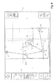
FIG. 3 a display representation of an electronic field book with five laser scans from different scan positions before the relative positioning of the last laser scan and -
FIG. 4 the electronic field book according toFIG. 3 after the relative positioning and a rearrangement of the combination of individual scan positions / laser scans.
In
Im Folgenden werden dann manuell oder automatisch die Grundrisse 6, 8 und die Scanpositionen 2, 4 so lange verschoben und gedreht bis die Grundrisse 6, 8 gemäß der Darstellung in
Die Scanposition 4 des zuletzt aufgenommenen Laserscans ist dabei farblich von derjenigen des zuvor aufgenommenen Laserscans abgesetzt. Nach dem Scan wird dann die Scanposition 4 des zuletzt aufgenommenen Laserscans mit dem zugehörigen Grundriss 8 über auf dem als Bedienoberfläche ausgebildeten Touchscreen-Display dargestellte Softkeys in Überdeckung gebracht, wobei der Grundriss gedreht, verschoben oder auf sonstige Weise positioniert werden kann.The
Bei der automatischen (Target losen) Registrierung der einzelnen Laserscans zueinander ist es besonders wichtig, daß nur solche Scans vom Registrierungs-Algorithmus bearbeitet werden, die auch einen gemeinsamen Überlappungsbereich aufweisen. Ist dieser Bereich nicht ausreichend, wird der Algorithmus nur unnötig Rechenzeit beanspruchen ohne jemals zu einem Ergebnis gelangen zu können. Bei realen Scanprojekten werden jedoch Dutzende wenn nicht Hunderte von Laserscans aufgenommen, so daß es sehr wichtig ist zu vermerken, welcher Scan mit welchem überlappende Bereiche hat - nur diese werden überhaupt dem Registrierungs-Algorithmus zur Registrierung übergeben. Diese Markierung erfolgt zunächst automatisch (zwischen dem aktuellen und dem vorherigen Laserscan), kann jedoch durch den Bediener des Laserscanners vor Ort oder nachträglich (in der Auswert-Software zur Registrierung) abgeändert werden. Die Markierung besteht aus graphischen Symbolen (schwarze Pfeile), die alle Scans mit gemeinsamem Überlappungsbereich verbinden.In the automatic (target-less) registration of the individual laser scans to each other, it is particularly important that only those scans are processed by the registration algorithm, which also have a common overlap area. If this range is not sufficient, the algorithm will only take up computing time unnecessarily without ever being able to arrive at a result. However, in real scanning projects, scores, if not hundreds, of laser scans are recorded so it is very important to note which scan has which overlapping areas - only these are ever submitted to the registration algorithm for registration. This marking is initially automatic (between the current and the previous laser scan), but can be changed by the operator of the laser scanner on site or subsequently (in the evaluation software for registration). The marker consists of graphic symbols (black arrows) that connect all scans with a common overlap area.
Die graphische Darstellung der Scannerstandpunkte und Verknüpfungen ist jedoch nicht nur für die Registrierung erforderlich, sondern verschafft dem Anwender eine graphische Übersicht und Orientierung bei größeren Scanprojekten. Ohne diese Orientierung hätte der Anwender schon vor Ort Schwierigkeiten festzustellen, ob er überhaupt genügend Standpunkte zur Erfassung der Umgebung gewählt hat. Nachträglich wäre es völlig unmöglich festzustellen wo welcher Scan aufgenommen wurde. Bislang machen Anwender deshalb solche Skizzen händisch in ihrem als "Feldbuch" bezeichneten Notizbuch.However, the graphical representation of the scanner viewpoints and links is not only required for registration, but provides the user with a graphical overview and orientation for larger scanning projects. Without this orientation, the user would already have trouble finding out whether he has chosen enough points of view to capture the environment. Subsequently, it would be completely impossible to determine where which scan was taken. So far, users make such sketches by hand in their notebook called "field book".
Eine Verknüpfung mehrerer Laserscans ist in
Die Grundrisse der aus den Scanpositionen 2, 4, 12 und 14 erstellten Laserscans wurden bereits in der vorbeschriebenen Weise miteinander in Überdeckung gebracht. Diese Grundrisskontur ist in der Darstellung gemäß
Eine Besonderheit des vermessenen Objektes besteht beim Ausführungsbeispiel gemäß
Zunächst wurde über den Softkey 32 die Verknüpfung zwischen den mit den Bezugszeichen 14 und 16 dargestellten Laserscans aufgehoben, da die Scanposition 14 so weit innerhalb des Gangs 46 liegt, dass die Scanposition 16 mit 14 keinen gemeinsamen Überlappungsbereich aufweist. Entsprechendes gilt natürlich auch in umgekehrter Weise. Über den Softkey 32 wird darauf eine Verknüpfung zwischen den Scanpositionen 12 und 16 hergestellt, so dass der Scanposition 12 insgesamt drei Verknüpfungen zugeordnet sind und somit alle drei, wie eingangs beschrieben, automatisch registriert werden können.First, the link between the laser scans represented by the
Bei den beschriebenen Ausführungsbeispielen erfolgte die grobe Relativpositionierung manuell durch Betätigung der zugeordneten Softkeys. Sie kann jedoch auch automatisch durch im Laserscanner eingebaute Positionierungs-Systeme, wie etwa GPS oder eine kostengünstige MEMS-IMU (inertiales Navigationssystem) erfolgen. In allen Fällen muß diese manuelle Vorpositionierung nicht mit hoher Genauigkeit erfolgen, sondern es reicht in der Regel aus, mit geringer Genauigkeit die Grundrisse nur etwa in Überdeckung zu bringen. Die exakte Positionierung bzw. Orientierung erfolgt ohnehin erst in der Auswertesoftware zur automatischen Registrierung. Nach dieser Registrierung werden die exakten Positionen im Feldbuch der Auswertesoftware (die weitgehend dem Feldbuch am Laserscanner entspricht) angezeigt.In the described embodiments, the coarse relative positioning was done manually by pressing the associated softkeys. However, it can also be done automatically by built-in laser scanner positioning systems, such as GPS or a low-cost MEMS IMU (inertial navigation system). In all cases, this manual pre-positioning must not be done with high accuracy, but it is usually sufficient to bring the floor plans only slightly overlapping with low accuracy. The exact positioning or orientation takes place anyway in the evaluation software for automatic registration. After this registration, the exact positions in the field book of the evaluation software (which largely corresponds to the field book on the laser scanner) are displayed.
Davon unabhängig ist die bisher übliche Registrierung anhand von speziellen Targets weiterhin möglich, wobei beide Verfahren jeweils allein oder in beliebiger Kombination benutzt werden können. So ist die Verwendung der bisherigen Targets immer dann unerläßlich, wenn Laserscans in tachymetrisch aufgemessene Anlagenkoordinaten überführt werden müssen.Irrespective of this, the previously customary registration using special targets is still possible, with both methods being able to be used alone or in any desired combination. Thus, the use of the previous targets is always essential when laser scans must be transferred to tachymetrically measured system coordinates.
- 22
- Scanpositionscanning position
- 44
- Scanpositionscanning position
- 66
- GrundrissLayout
- 88th
- GrundrissLayout
- 1010
- Displaydisplay
- 1212
- Scanpositionscanning position
- 1414
- Scanpositionscanning position
- 1616
- Scanpositionscanning position
- 1818
- Verknüpfungshortcut
- 2020
- Verknüpfungshortcut
- 2222
- Verknüpfungshortcut
- 2424
- Verknüpfungshortcut
- 2626
- GrundrisskonturPlan outline
- 2828
- Softkeysoftkey
- 3030
- Softkeysoftkey
- 3232
- Softkeysoftkey
- 3434
- Softkeysoftkey
- 3636
- Softkeysoftkey
- 3838
- Softkeysoftkey
- 4040
- Softkeysoftkey
- 4242
- Softkeysoftkey
Claims (13)
Applications Claiming Priority (3)
| Application Number | Priority Date | Filing Date | Title |
|---|---|---|---|
| DE102012105937 | 2012-07-03 | ||
| DE102012107226 | 2012-08-07 | ||
| DE102013102286.3A DE102013102286A1 (en) | 2012-07-03 | 2013-03-07 | Method and device for evaluating laser scans |
Publications (2)
| Publication Number | Publication Date |
|---|---|
| EP2682783A1 true EP2682783A1 (en) | 2014-01-08 |
| EP2682783B1 EP2682783B1 (en) | 2018-08-29 |
Family
ID=48746325
Family Applications (1)
| Application Number | Title | Priority Date | Filing Date |
|---|---|---|---|
| EP13174556.4A Active EP2682783B1 (en) | 2012-07-03 | 2013-07-01 | Method and device for evaluating laser scans |
Country Status (2)
| Country | Link |
|---|---|
| EP (1) | EP2682783B1 (en) |
| DE (1) | DE102013102286A1 (en) |
Cited By (4)
| Publication number | Priority date | Publication date | Assignee | Title |
|---|---|---|---|---|
| WO2015153393A1 (en) * | 2014-04-02 | 2015-10-08 | Faro Technologies, Inc. | Registering of a scene disintegrating into clusters with visualized clusters |
| US9245346B2 (en) | 2014-04-02 | 2016-01-26 | Faro Technologies, Inc. | Registering of a scene disintegrating into clusters with pairs of scans |
| DE102014110992A1 (en) * | 2014-08-01 | 2016-02-04 | Faro Technologies Inc. | Register a clustered scene with location tracking |
| DE102014110995A1 (en) * | 2014-08-01 | 2016-02-04 | Faro Technologies, Inc. | Registration of a clustered scene with scan request |
Families Citing this family (1)
| Publication number | Priority date | Publication date | Assignee | Title |
|---|---|---|---|---|
| WO2016128575A1 (en) * | 2015-02-13 | 2016-08-18 | Zoller + Fröhlich GmbH | Device and method for measuring an object |
Citations (2)
| Publication number | Priority date | Publication date | Assignee | Title |
|---|---|---|---|---|
| DE102009015922A1 (en) * | 2009-03-25 | 2010-10-07 | Faro Technologies, Inc., Lake Mary | Method for optically scanning and measuring a scene |
| EP2322901A2 (en) * | 2009-11-16 | 2011-05-18 | Riegl Laser Measurement Systems GmbH | Method for improving position and orientation measurement data |
Family Cites Families (3)
| Publication number | Priority date | Publication date | Assignee | Title |
|---|---|---|---|---|
| CN100578525C (en) * | 2002-07-10 | 2010-01-06 | 哈曼贝克自动系统股份有限公司 | System and methodfor generating three-dimensional electronic models of objects |
| DE102008034198B4 (en) | 2008-07-21 | 2014-01-23 | Zoller & Fröhlich GmbH | Target and method for evaluating scans |
| DE102009055626A1 (en) * | 2009-11-25 | 2011-05-26 | Ralph Klose | Optical measuring device for optical measurement of maize plant, has evaluation device evaluating distance signal of camera pixels to determine three-dimensional enveloped surface of measuring object to be detected in measuring region |
-
2013
- 2013-03-07 DE DE102013102286.3A patent/DE102013102286A1/en active Pending
- 2013-07-01 EP EP13174556.4A patent/EP2682783B1/en active Active
Patent Citations (2)
| Publication number | Priority date | Publication date | Assignee | Title |
|---|---|---|---|---|
| DE102009015922A1 (en) * | 2009-03-25 | 2010-10-07 | Faro Technologies, Inc., Lake Mary | Method for optically scanning and measuring a scene |
| EP2322901A2 (en) * | 2009-11-16 | 2011-05-18 | Riegl Laser Measurement Systems GmbH | Method for improving position and orientation measurement data |
Non-Patent Citations (1)
| Title |
|---|
| HUIJING ZHAO ET AL: "A ROBUST METHOD FOR REGISTERING GROUND-BASED LASER RANGE IMAGES OF URBAN OUTDOOR OBJECTS", PHOTOGRAMMETRIC ENGINEERING AND REMOTE SENSING, vol. 67, no. 10, 2001, pages 1143 - 1153, XP007913994 * |
Cited By (9)
| Publication number | Priority date | Publication date | Assignee | Title |
|---|---|---|---|---|
| WO2015153393A1 (en) * | 2014-04-02 | 2015-10-08 | Faro Technologies, Inc. | Registering of a scene disintegrating into clusters with visualized clusters |
| US9245346B2 (en) | 2014-04-02 | 2016-01-26 | Faro Technologies, Inc. | Registering of a scene disintegrating into clusters with pairs of scans |
| US9342890B2 (en) | 2014-04-02 | 2016-05-17 | Faro Technologies, Inc. | Registering of a scene disintegrating into clusters with visualized clusters |
| GB2538929A (en) * | 2014-04-02 | 2016-11-30 | Faro Tech Inc | Registering of a scene disintegrating into clusters with visualized clusters |
| GB2538929B (en) * | 2014-04-02 | 2018-06-06 | Faro Tech Inc | Registering of a scene disintegrating into clusters with visualized clusters |
| DE102014110992A1 (en) * | 2014-08-01 | 2016-02-04 | Faro Technologies Inc. | Register a clustered scene with location tracking |
| DE102014110995A1 (en) * | 2014-08-01 | 2016-02-04 | Faro Technologies, Inc. | Registration of a clustered scene with scan request |
| US9746311B2 (en) | 2014-08-01 | 2017-08-29 | Faro Technologies, Inc. | Registering of a scene disintegrating into clusters with position tracking |
| US9989353B2 (en) | 2014-08-01 | 2018-06-05 | Faro Technologies, Inc. | Registering of a scene disintegrating into clusters with position tracking |
Also Published As
| Publication number | Publication date |
|---|---|
| EP2682783B1 (en) | 2018-08-29 |
| DE102013102286A1 (en) | 2014-01-09 |
Similar Documents
| Publication | Publication Date | Title |
|---|---|---|
| EP3056923B1 (en) | Scanning assembly and method for scanning an object | |
| EP2682783B1 (en) | Method and device for evaluating laser scans | |
| DE102016105496A1 (en) | System for checking objects using augmented reality | |
| EP2063226A2 (en) | Device and method for providing information about interesting locations with a navigation system | |
| DE102009012590A1 (en) | Device for determining the position of a robot arm with camera for taking pictures | |
| EP3725472A1 (en) | Method for determining a trajectory of a robot | |
| WO2010086261A1 (en) | Model assembly of a production plant having true-to-scale models of production devices and method for entering a spatial assembly of production devices into a computer-aided planning program | |
| DE102018113336A1 (en) | A method of using a machine to set an augmented reality display environment | |
| DE102010018634A1 (en) | Method for entering a spatial structure of manufacturing facilities in a computer-aided planning program and its optimization | |
| WO2020156890A1 (en) | Method for monitoring a building site | |
| DE102007016502B4 (en) | Measuring method and measuring system for measuring tools | |
| DE102018132921A1 (en) | Method for operating a field device of automation technology in an augmented reality / mixed reality environment | |
| EP2866053B1 (en) | Method for calibrating the position of a construction machine in a construction site plan | |
| EP2570768A1 (en) | Measuring device and method for filtered presentation of object information | |
| EP2118618B1 (en) | Method for determining measuring points | |
| EP2830305B1 (en) | Display device for a motor vehicle and method for operating such a display device | |
| DE102014104714A1 (en) | Method for aligning at least one physical component or physical component group with a virtual model of the component or component group | |
| DE102020204677A1 (en) | Tracking system and method for compensation of visual shadows when tracking measurement objects | |
| DE102019216607A1 (en) | Method and device for providing radar data | |
| DE102015122599A1 (en) | A display system and method of operating a display system in a vehicle having at least first and second display surfaces | |
| DE102019208498A1 (en) | Method for optimizing an environment model | |
| WO2013057192A1 (en) | Method for surveying and visually displaying the physical circumstances of a production plant | |
| EP2043940B1 (en) | Method to make automatically available cartographic data in a container crane system, container crane system and control program | |
| DE102017107570A1 (en) | marking | |
| DE102016124826A1 (en) | Method and apparatus for determining a local coordinate orientation of sensors in a sensor network |
Legal Events
| Date | Code | Title | Description |
|---|---|---|---|
| PUAI | Public reference made under article 153(3) epc to a published international application that has entered the european phase |
Free format text: ORIGINAL CODE: 0009012 |
|
| AK | Designated contracting states |
Kind code of ref document: A1 Designated state(s): AL AT BE BG CH CY CZ DE DK EE ES FI FR GB GR HR HU IE IS IT LI LT LU LV MC MK MT NL NO PL PT RO RS SE SI SK SM TR |
|
| AX | Request for extension of the european patent |
Extension state: BA ME |
|
| 17P | Request for examination filed |
Effective date: 20140320 |
|
| RBV | Designated contracting states (corrected) |
Designated state(s): AL AT BE BG CH CY CZ DE DK EE ES FI FR GB GR HR HU IE IS IT LI LT LU LV MC MK MT NL NO PL PT RO RS SE SI SK SM TR |
|
| 17Q | First examination report despatched |
Effective date: 20160615 |
|
| STAA | Information on the status of an ep patent application or granted ep patent |
Free format text: STATUS: EXAMINATION IS IN PROGRESS |
|
| GRAP | Despatch of communication of intention to grant a patent |
Free format text: ORIGINAL CODE: EPIDOSNIGR1 |
|
| STAA | Information on the status of an ep patent application or granted ep patent |
Free format text: STATUS: GRANT OF PATENT IS INTENDED |
|
| INTG | Intention to grant announced |
Effective date: 20180319 |
|
| GRAS | Grant fee paid |
Free format text: ORIGINAL CODE: EPIDOSNIGR3 |
|
| GRAA | (expected) grant |
Free format text: ORIGINAL CODE: 0009210 |
|
| STAA | Information on the status of an ep patent application or granted ep patent |
Free format text: STATUS: THE PATENT HAS BEEN GRANTED |
|
| AK | Designated contracting states |
Kind code of ref document: B1 Designated state(s): AL AT BE BG CH CY CZ DE DK EE ES FI FR GB GR HR HU IE IS IT LI LT LU LV MC MK MT NL NO PL PT RO RS SE SI SK SM TR |
|
| REG | Reference to a national code |
Ref country code: GB Ref legal event code: FG4D Free format text: NOT ENGLISH |
|
| REG | Reference to a national code |
Ref country code: CH Ref legal event code: EP |
|
| REG | Reference to a national code |
Ref country code: AT Ref legal event code: REF Ref document number: 1035771 Country of ref document: AT Kind code of ref document: T Effective date: 20180915 |
|
| REG | Reference to a national code |
Ref country code: IE Ref legal event code: FG4D Free format text: LANGUAGE OF EP DOCUMENT: GERMAN |
|
| REG | Reference to a national code |
Ref country code: DE Ref legal event code: R096 Ref document number: 502013010953 Country of ref document: DE |
|
| REG | Reference to a national code |
Ref country code: CH Ref legal event code: NV Representative=s name: SCHMAUDER AND PARTNER AG PATENT- UND MARKENANW, CH |
|
| REG | Reference to a national code |
Ref country code: NL Ref legal event code: FP |
|
| REG | Reference to a national code |
Ref country code: SE Ref legal event code: TRGR |
|
| REG | Reference to a national code |
Ref country code: LT Ref legal event code: MG4D |
|
| PG25 | Lapsed in a contracting state [announced via postgrant information from national office to epo] |
Ref country code: GR Free format text: LAPSE BECAUSE OF FAILURE TO SUBMIT A TRANSLATION OF THE DESCRIPTION OR TO PAY THE FEE WITHIN THE PRESCRIBED TIME-LIMIT Effective date: 20181130 Ref country code: RS Free format text: LAPSE BECAUSE OF FAILURE TO SUBMIT A TRANSLATION OF THE DESCRIPTION OR TO PAY THE FEE WITHIN THE PRESCRIBED TIME-LIMIT Effective date: 20180829 Ref country code: FI Free format text: LAPSE BECAUSE OF FAILURE TO SUBMIT A TRANSLATION OF THE DESCRIPTION OR TO PAY THE FEE WITHIN THE PRESCRIBED TIME-LIMIT Effective date: 20180829 Ref country code: NO Free format text: LAPSE BECAUSE OF FAILURE TO SUBMIT A TRANSLATION OF THE DESCRIPTION OR TO PAY THE FEE WITHIN THE PRESCRIBED TIME-LIMIT Effective date: 20181129 Ref country code: BG Free format text: LAPSE BECAUSE OF FAILURE TO SUBMIT A TRANSLATION OF THE DESCRIPTION OR TO PAY THE FEE WITHIN THE PRESCRIBED TIME-LIMIT Effective date: 20181129 Ref country code: IS Free format text: LAPSE BECAUSE OF FAILURE TO SUBMIT A TRANSLATION OF THE DESCRIPTION OR TO PAY THE FEE WITHIN THE PRESCRIBED TIME-LIMIT Effective date: 20181229 Ref country code: LT Free format text: LAPSE BECAUSE OF FAILURE TO SUBMIT A TRANSLATION OF THE DESCRIPTION OR TO PAY THE FEE WITHIN THE PRESCRIBED TIME-LIMIT Effective date: 20180829 |
|
| PG25 | Lapsed in a contracting state [announced via postgrant information from national office to epo] |
Ref country code: AL Free format text: LAPSE BECAUSE OF FAILURE TO SUBMIT A TRANSLATION OF THE DESCRIPTION OR TO PAY THE FEE WITHIN THE PRESCRIBED TIME-LIMIT Effective date: 20180829 Ref country code: LV Free format text: LAPSE BECAUSE OF FAILURE TO SUBMIT A TRANSLATION OF THE DESCRIPTION OR TO PAY THE FEE WITHIN THE PRESCRIBED TIME-LIMIT Effective date: 20180829 Ref country code: HR Free format text: LAPSE BECAUSE OF FAILURE TO SUBMIT A TRANSLATION OF THE DESCRIPTION OR TO PAY THE FEE WITHIN THE PRESCRIBED TIME-LIMIT Effective date: 20180829 |
|
| PG25 | Lapsed in a contracting state [announced via postgrant information from national office to epo] |
Ref country code: EE Free format text: LAPSE BECAUSE OF FAILURE TO SUBMIT A TRANSLATION OF THE DESCRIPTION OR TO PAY THE FEE WITHIN THE PRESCRIBED TIME-LIMIT Effective date: 20180829 Ref country code: PL Free format text: LAPSE BECAUSE OF FAILURE TO SUBMIT A TRANSLATION OF THE DESCRIPTION OR TO PAY THE FEE WITHIN THE PRESCRIBED TIME-LIMIT Effective date: 20180829 Ref country code: ES Free format text: LAPSE BECAUSE OF FAILURE TO SUBMIT A TRANSLATION OF THE DESCRIPTION OR TO PAY THE FEE WITHIN THE PRESCRIBED TIME-LIMIT Effective date: 20180829 Ref country code: RO Free format text: LAPSE BECAUSE OF FAILURE TO SUBMIT A TRANSLATION OF THE DESCRIPTION OR TO PAY THE FEE WITHIN THE PRESCRIBED TIME-LIMIT Effective date: 20180829 Ref country code: CZ Free format text: LAPSE BECAUSE OF FAILURE TO SUBMIT A TRANSLATION OF THE DESCRIPTION OR TO PAY THE FEE WITHIN THE PRESCRIBED TIME-LIMIT Effective date: 20180829 |
|
| PG25 | Lapsed in a contracting state [announced via postgrant information from national office to epo] |
Ref country code: SK Free format text: LAPSE BECAUSE OF FAILURE TO SUBMIT A TRANSLATION OF THE DESCRIPTION OR TO PAY THE FEE WITHIN THE PRESCRIBED TIME-LIMIT Effective date: 20180829 Ref country code: SM Free format text: LAPSE BECAUSE OF FAILURE TO SUBMIT A TRANSLATION OF THE DESCRIPTION OR TO PAY THE FEE WITHIN THE PRESCRIBED TIME-LIMIT Effective date: 20180829 Ref country code: DK Free format text: LAPSE BECAUSE OF FAILURE TO SUBMIT A TRANSLATION OF THE DESCRIPTION OR TO PAY THE FEE WITHIN THE PRESCRIBED TIME-LIMIT Effective date: 20180829 |
|
| REG | Reference to a national code |
Ref country code: DE Ref legal event code: R097 Ref document number: 502013010953 Country of ref document: DE |
|
| PLBE | No opposition filed within time limit |
Free format text: ORIGINAL CODE: 0009261 |
|
| STAA | Information on the status of an ep patent application or granted ep patent |
Free format text: STATUS: NO OPPOSITION FILED WITHIN TIME LIMIT |
|
| 26N | No opposition filed |
Effective date: 20190531 |
|
| PG25 | Lapsed in a contracting state [announced via postgrant information from national office to epo] |
Ref country code: SI Free format text: LAPSE BECAUSE OF FAILURE TO SUBMIT A TRANSLATION OF THE DESCRIPTION OR TO PAY THE FEE WITHIN THE PRESCRIBED TIME-LIMIT Effective date: 20180829 |
|
| PG25 | Lapsed in a contracting state [announced via postgrant information from national office to epo] |
Ref country code: MC Free format text: LAPSE BECAUSE OF FAILURE TO SUBMIT A TRANSLATION OF THE DESCRIPTION OR TO PAY THE FEE WITHIN THE PRESCRIBED TIME-LIMIT Effective date: 20180829 |
|
| GBPC | Gb: european patent ceased through non-payment of renewal fee |
Effective date: 20190701 |
|
| PG25 | Lapsed in a contracting state [announced via postgrant information from national office to epo] |
Ref country code: TR Free format text: LAPSE BECAUSE OF FAILURE TO SUBMIT A TRANSLATION OF THE DESCRIPTION OR TO PAY THE FEE WITHIN THE PRESCRIBED TIME-LIMIT Effective date: 20180829 |
|
| REG | Reference to a national code |
Ref country code: BE Ref legal event code: MM Effective date: 20190731 |
|
| PG25 | Lapsed in a contracting state [announced via postgrant information from national office to epo] |
Ref country code: GB Free format text: LAPSE BECAUSE OF NON-PAYMENT OF DUE FEES Effective date: 20190701 |
|
| PG25 | Lapsed in a contracting state [announced via postgrant information from national office to epo] |
Ref country code: BE Free format text: LAPSE BECAUSE OF NON-PAYMENT OF DUE FEES Effective date: 20190731 Ref country code: LU Free format text: LAPSE BECAUSE OF NON-PAYMENT OF DUE FEES Effective date: 20190701 |
|
| PG25 | Lapsed in a contracting state [announced via postgrant information from national office to epo] |
Ref country code: PT Free format text: LAPSE BECAUSE OF FAILURE TO SUBMIT A TRANSLATION OF THE DESCRIPTION OR TO PAY THE FEE WITHIN THE PRESCRIBED TIME-LIMIT Effective date: 20181229 |
|
| PG25 | Lapsed in a contracting state [announced via postgrant information from national office to epo] |
Ref country code: IE Free format text: LAPSE BECAUSE OF NON-PAYMENT OF DUE FEES Effective date: 20190701 |
|
| PG25 | Lapsed in a contracting state [announced via postgrant information from national office to epo] |
Ref country code: CY Free format text: LAPSE BECAUSE OF FAILURE TO SUBMIT A TRANSLATION OF THE DESCRIPTION OR TO PAY THE FEE WITHIN THE PRESCRIBED TIME-LIMIT Effective date: 20180829 |
|
| PG25 | Lapsed in a contracting state [announced via postgrant information from national office to epo] |
Ref country code: MT Free format text: LAPSE BECAUSE OF FAILURE TO SUBMIT A TRANSLATION OF THE DESCRIPTION OR TO PAY THE FEE WITHIN THE PRESCRIBED TIME-LIMIT Effective date: 20180829 Ref country code: HU Free format text: LAPSE BECAUSE OF FAILURE TO SUBMIT A TRANSLATION OF THE DESCRIPTION OR TO PAY THE FEE WITHIN THE PRESCRIBED TIME-LIMIT; INVALID AB INITIO Effective date: 20130701 |
|
| PG25 | Lapsed in a contracting state [announced via postgrant information from national office to epo] |
Ref country code: MK Free format text: LAPSE BECAUSE OF FAILURE TO SUBMIT A TRANSLATION OF THE DESCRIPTION OR TO PAY THE FEE WITHIN THE PRESCRIBED TIME-LIMIT Effective date: 20180829 |
|
| PGFP | Annual fee paid to national office [announced via postgrant information from national office to epo] |
Ref country code: NL Payment date: 20230720 Year of fee payment: 11 |
|
| PGFP | Annual fee paid to national office [announced via postgrant information from national office to epo] |
Ref country code: IT Payment date: 20230731 Year of fee payment: 11 Ref country code: CH Payment date: 20230801 Year of fee payment: 11 Ref country code: AT Payment date: 20230718 Year of fee payment: 11 |
|
| PGFP | Annual fee paid to national office [announced via postgrant information from national office to epo] |
Ref country code: SE Payment date: 20230724 Year of fee payment: 11 Ref country code: FR Payment date: 20230724 Year of fee payment: 11 Ref country code: DE Payment date: 20230613 Year of fee payment: 11 |