EP2682723A1 - Spectroscopic image capturing apparatus - Google Patents
Spectroscopic image capturing apparatus Download PDFInfo
- Publication number
- EP2682723A1 EP2682723A1 EP13174298.3A EP13174298A EP2682723A1 EP 2682723 A1 EP2682723 A1 EP 2682723A1 EP 13174298 A EP13174298 A EP 13174298A EP 2682723 A1 EP2682723 A1 EP 2682723A1
- Authority
- EP
- European Patent Office
- Prior art keywords
- polarizer
- light
- image capturing
- capturing apparatus
- polarized light
- Prior art date
- Legal status (The legal status is an assumption and is not a legal conclusion. Google has not performed a legal analysis and makes no representation as to the accuracy of the status listed.)
- Withdrawn
Links
- 238000003384 imaging method Methods 0.000 claims abstract description 45
- 230000003287 optical effect Effects 0.000 claims abstract description 36
- 230000010287 polarization Effects 0.000 claims description 27
- 239000000306 component Substances 0.000 description 23
- 238000010586 diagram Methods 0.000 description 14
- VYPSYNLAJGMNEJ-UHFFFAOYSA-N Silicium dioxide Chemical compound O=[Si]=O VYPSYNLAJGMNEJ-UHFFFAOYSA-N 0.000 description 10
- 239000000758 substrate Substances 0.000 description 10
- 230000004907 flux Effects 0.000 description 8
- 238000004611 spectroscopical analysis Methods 0.000 description 8
- 230000003595 spectral effect Effects 0.000 description 7
- 235000013305 food Nutrition 0.000 description 6
- 239000011521 glass Substances 0.000 description 5
- 238000004458 analytical method Methods 0.000 description 4
- 238000000034 method Methods 0.000 description 4
- 239000000377 silicon dioxide Substances 0.000 description 4
- 230000000694 effects Effects 0.000 description 3
- 235000012239 silicon dioxide Nutrition 0.000 description 3
- MCMNRKCIXSYSNV-UHFFFAOYSA-N ZrO2 Inorganic materials O=[Zr]=O MCMNRKCIXSYSNV-UHFFFAOYSA-N 0.000 description 2
- BJQHLKABXJIVAM-UHFFFAOYSA-N bis(2-ethylhexyl) phthalate Chemical compound CCCCC(CC)COC(=O)C1=CC=CC=C1C(=O)OCC(CC)CCCC BJQHLKABXJIVAM-UHFFFAOYSA-N 0.000 description 2
- 238000006243 chemical reaction Methods 0.000 description 2
- ORUIBWPALBXDOA-UHFFFAOYSA-L magnesium fluoride Chemical compound [F-].[F-].[Mg+2] ORUIBWPALBXDOA-UHFFFAOYSA-L 0.000 description 2
- 238000005259 measurement Methods 0.000 description 2
- 239000000203 mixture Substances 0.000 description 2
- ZKATWMILCYLAPD-UHFFFAOYSA-N niobium pentoxide Inorganic materials O=[Nb](=O)O[Nb](=O)=O ZKATWMILCYLAPD-UHFFFAOYSA-N 0.000 description 2
- URLJKFSTXLNXLG-UHFFFAOYSA-N niobium(5+);oxygen(2-) Chemical compound [O-2].[O-2].[O-2].[O-2].[O-2].[Nb+5].[Nb+5] URLJKFSTXLNXLG-UHFFFAOYSA-N 0.000 description 2
- 230000010355 oscillation Effects 0.000 description 2
- TWNQGVIAIRXVLR-UHFFFAOYSA-N oxo(oxoalumanyloxy)alumane Chemical compound O=[Al]O[Al]=O TWNQGVIAIRXVLR-UHFFFAOYSA-N 0.000 description 2
- BPUBBGLMJRNUCC-UHFFFAOYSA-N oxygen(2-);tantalum(5+) Chemical compound [O-2].[O-2].[O-2].[O-2].[O-2].[Ta+5].[Ta+5] BPUBBGLMJRNUCC-UHFFFAOYSA-N 0.000 description 2
- RVTZCBVAJQQJTK-UHFFFAOYSA-N oxygen(2-);zirconium(4+) Chemical compound [O-2].[O-2].[Zr+4] RVTZCBVAJQQJTK-UHFFFAOYSA-N 0.000 description 2
- PBCFLUZVCVVTBY-UHFFFAOYSA-N tantalum pentoxide Inorganic materials O=[Ta](=O)O[Ta](=O)=O PBCFLUZVCVVTBY-UHFFFAOYSA-N 0.000 description 2
- ZLMJMSJWJFRBEC-UHFFFAOYSA-N Potassium Chemical compound [K] ZLMJMSJWJFRBEC-UHFFFAOYSA-N 0.000 description 1
- CDBYLPFSWZWCQE-UHFFFAOYSA-L Sodium Carbonate Chemical compound [Na+].[Na+].[O-]C([O-])=O CDBYLPFSWZWCQE-UHFFFAOYSA-L 0.000 description 1
- GWEVSGVZZGPLCZ-UHFFFAOYSA-N Titan oxide Chemical compound O=[Ti]=O GWEVSGVZZGPLCZ-UHFFFAOYSA-N 0.000 description 1
- 230000001154 acute effect Effects 0.000 description 1
- 239000003513 alkali Substances 0.000 description 1
- 239000005388 borosilicate glass Substances 0.000 description 1
- 235000012041 food component Nutrition 0.000 description 1
- 239000005428 food component Substances 0.000 description 1
- CJNBYAVZURUTKZ-UHFFFAOYSA-N hafnium(iv) oxide Chemical compound O=[Hf]=O CJNBYAVZURUTKZ-UHFFFAOYSA-N 0.000 description 1
- 239000005355 lead glass Substances 0.000 description 1
- 239000000463 material Substances 0.000 description 1
- 229910052751 metal Inorganic materials 0.000 description 1
- 239000002184 metal Substances 0.000 description 1
- 229910052700 potassium Inorganic materials 0.000 description 1
- 239000011591 potassium Substances 0.000 description 1
- 239000010453 quartz Substances 0.000 description 1
- 229910052709 silver Inorganic materials 0.000 description 1
- 239000004332 silver Substances 0.000 description 1
- 230000001629 suppression Effects 0.000 description 1
- ZCUFMDLYAMJYST-UHFFFAOYSA-N thorium dioxide Chemical compound O=[Th]=O ZCUFMDLYAMJYST-UHFFFAOYSA-N 0.000 description 1
- WFKWXMTUELFFGS-UHFFFAOYSA-N tungsten Chemical compound [W] WFKWXMTUELFFGS-UHFFFAOYSA-N 0.000 description 1
- 229910052721 tungsten Inorganic materials 0.000 description 1
- 239000010937 tungsten Substances 0.000 description 1
Images




Classifications
-
- G—PHYSICS
- G01—MEASURING; TESTING
- G01N—INVESTIGATING OR ANALYSING MATERIALS BY DETERMINING THEIR CHEMICAL OR PHYSICAL PROPERTIES
- G01N21/00—Investigating or analysing materials by the use of optical means, i.e. using sub-millimetre waves, infrared, visible or ultraviolet light
- G01N21/17—Systems in which incident light is modified in accordance with the properties of the material investigated
- G01N21/25—Colour; Spectral properties, i.e. comparison of effect of material on the light at two or more different wavelengths or wavelength bands
- G01N21/255—Details, e.g. use of specially adapted sources, lighting or optical systems
-
- G—PHYSICS
- G01—MEASURING; TESTING
- G01J—MEASUREMENT OF INTENSITY, VELOCITY, SPECTRAL CONTENT, POLARISATION, PHASE OR PULSE CHARACTERISTICS OF INFRARED, VISIBLE OR ULTRAVIOLET LIGHT; COLORIMETRY; RADIATION PYROMETRY
- G01J3/00—Spectrometry; Spectrophotometry; Monochromators; Measuring colours
- G01J3/02—Details
- G01J3/0297—Constructional arrangements for removing other types of optical noise or for performing calibration
-
- G—PHYSICS
- G01—MEASURING; TESTING
- G01J—MEASUREMENT OF INTENSITY, VELOCITY, SPECTRAL CONTENT, POLARISATION, PHASE OR PULSE CHARACTERISTICS OF INFRARED, VISIBLE OR ULTRAVIOLET LIGHT; COLORIMETRY; RADIATION PYROMETRY
- G01J3/00—Spectrometry; Spectrophotometry; Monochromators; Measuring colours
- G01J3/02—Details
- G01J3/0205—Optical elements not provided otherwise, e.g. optical manifolds, diffusers, windows
- G01J3/0224—Optical elements not provided otherwise, e.g. optical manifolds, diffusers, windows using polarising or depolarising elements
-
- G—PHYSICS
- G01—MEASURING; TESTING
- G01J—MEASUREMENT OF INTENSITY, VELOCITY, SPECTRAL CONTENT, POLARISATION, PHASE OR PULSE CHARACTERISTICS OF INFRARED, VISIBLE OR ULTRAVIOLET LIGHT; COLORIMETRY; RADIATION PYROMETRY
- G01J3/00—Spectrometry; Spectrophotometry; Monochromators; Measuring colours
- G01J3/28—Investigating the spectrum
- G01J3/2823—Imaging spectrometer
-
- G—PHYSICS
- G01—MEASURING; TESTING
- G01J—MEASUREMENT OF INTENSITY, VELOCITY, SPECTRAL CONTENT, POLARISATION, PHASE OR PULSE CHARACTERISTICS OF INFRARED, VISIBLE OR ULTRAVIOLET LIGHT; COLORIMETRY; RADIATION PYROMETRY
- G01J3/00—Spectrometry; Spectrophotometry; Monochromators; Measuring colours
- G01J3/28—Investigating the spectrum
- G01J3/2823—Imaging spectrometer
- G01J2003/2826—Multispectral imaging, e.g. filter imaging
Definitions
- the present invention relates to a spectroscopic image capturing apparatus.
- the method for acquiring spectral data on a specific portion of an object described in JP-A-2000-329617 includes providing an image data acquisition apparatus that captures an image of the entire object to acquire an image of the object and a spectral data acquisition apparatus that acquires spectral data in an area narrower than the acquired image of the object and has higher wavelength resolution than the image data acquisition apparatus, using the image data acquisition apparatus to acquire general characteristics of the object, and using the spectral data acquisition apparatus to analyze a characteristic portion of the data in detail and acquire the analysis result.
- the spectroscopic image input system disclosed in JP-A-2000-329617 accommodates a unit that determines the specific portion and characterizes, that is, analyzes the object in a quick, stable manner without operator's (person's) judgment.
- JP-A-2009-33222 discloses an image capturing apparatus capable of producing a spectroscopic image of an object by using a single-panel digital camera but also using a spectroscopic filter having a narrow-band wavelength transmitting characteristic to acquire captured images of the object while changing the wavelength transmitting band and combining the acquired images of the wavelength bands.
- the spectroscopic image input system disclosed in JP-A-2000-329617 requires not only the image capturing apparatus for acquiring an image of an entire object but also the spectral data acquisition apparatus for acquiring a spectral image of a specific portion of the object, resulting in an increase in size of the system.
- providing a compact food checker in other words allows the apparatus to capture an image of an object close thereto, but measurement of food components and other parameters requires measurement of the interior of the obj ect instead of the surface thereof.
- JP-A-2009-33222 suggests a method used with the image capturing apparatus for capturing an image of an object close thereto but does not disclose an effect of specular reflection.
- An advantage of some aspects of the invention is to provide a spectroscopic image capturing apparatus capable of suppression of an effect of specular reflection and accurate spectroscopic analysis of an object.
- a spectroscopic image capturing apparatus includes a light source section and an imaging section.
- the light source section includes a light source portion, a first lens group, and a first polarizer
- the imaging section includes a second polarizer, a second lens group, an optical filter, and an imaging unit.
- the polarized light outputted from the first polarizer provided in the light source section is projected onto an object to be analyzed in terms of component, the polarized light reaches the interior of the object, and light reflected off internal components is the outputted light that is depolarized.
- light specularly reflected off the surface of the object is the outputted polarized light with its polarization maintained.
- the reflected light depolarized by the internal components of the object and the polarized light specularly reflected off the surface of the object, the mixture of which forms analyzed light, are incident on the imaging section.
- the second polarizer provided in the imaging section absorbs the polarized light in the incident analyzed light, and only the reflected light depolarized by the internal components of the object reaches the imaging unit.
- the imaging unit can receive analyzed light free of the component specularly reflected off the surface of the object, whereby the spectroscopic image capturing apparatus can form an image of the object for accurate spectroscopic analysis.
- each of the first polarizer and the second polarizer includes a linearly polarizing portion, and the first polarizer and the second polarizer are so disposed that the polarization direction of linearly polarized light produced by the first polarizer and the polarization direction of linearly polarized light produced by the second polarizer are perpendicular to each other.
- each of the first polarizer and the second polarizer is a linearly polarizing portion that polarizes light incident thereon into linearly polarized light, the amount of change (shift) in the polarization of the light specularly reflected off the surface of the object is small, whereby the imaging section can more reliably remove the specularly reflected light and the spectroscopic image capturing apparatus can hence form an image of the object for accurate spectroscopic analysis.
- each of the linearly polarizing portions is a linearly polarizing plate.
- the spectroscopic image capturing apparatus can be simply configured, and the polarization axes of the first polarizer and the second polarizer can be readily adjusted with respect to each other.
- each of the first polarizer and the second polarizer include a circularly polarizing portion, and the first polarizer and the second polarizer are so disposed that the rotation direction of circularly polarized light produced by the first polarizer and the rotation direction of circularly polarized light produced by the second polarizer are the same direction.
- each of the first polarizer and the second polarizer is a circularly polarizing portion that polarizes light incident thereon into circularly polarized light
- the amount of change (shift) in the polarization of the light specularly reflected off the surface of the object is small, whereby using circularly polarized light allows the imaging section to more reliably remove the specularly reflected light even when the positioning of the second polarizer around the optical axis is shifted and the spectroscopic image capturing apparatus can hence form an image of the object for accurate spectroscopic analysis.
- each of the circularly polarizing portions includes a ⁇ /4 retardation film.
- the optical filter is a variable wavelength optical filter.
- variable wavelength optical filter which allows selection of a wavelength region within which a spectroscopic image of a desired component from a variety of components contained in the object is acquired, allows a single spectroscopic image capturing apparatus to acquire a desired spectroscopic image.
- a spectroscopic image capturing apparatus includes a light source, a first polarizer, a second polarizer, an optical filter, and an imaging unit.
- the first polarizer is disposed in a first optical path between the light source and an obj ect to be imaged
- the second polarizer is disposed in a second optical path between the object to be imaged and the imaging unit.
- the polarized light outputted from the first polarizer provided in the light source section is projected onto an object to be analyzed in terms of component, the polarized light reaches the interior of the object, and light reflected off internal components is the outputted light that is depolarized.
- light specularly reflected off the surface of the object is the outputted polarized light with its polarization maintained.
- the reflected light depolarized by the internal components of the object and the polarized light specularly reflected off the surface of the object, the mixture of which forms analyzed light, are incident on the imaging unit.
- the second polarizer provided in the imaging section absorbs the polarized light in the incident analyzed light, and only the reflected light depolarized by the internal components of the object reaches the imaging unit.
- the imaging unit can receive analyzed light free of the component specularly reflected off the surface of the object, whereby the spectroscopic image capturing apparatus can form an image of the obj ect for accurate spectroscopic analysis.
- each of the first polarizer and the second polarizer include a linearly polarizing portion, and the first polarizer and the second polarizer are so disposed that the polarization direction of linearly polarized light produced by the first polarizer and the polarization direction of linearly polarized light produced by the second polarizer are perpendicular to each other.
- perpendicular used in the application example described above also does not mean exact 90-degree intersection but accepts a predetermined angular range around a target value of 90 degrees at least in consideration of positional precision in typical apparatus assembly or variations of parts themselves.
- each of the first polarizer and the second polarizer is a linearly polarizing portion that polarizes light incident thereon into linearly polarized light, the amount of change (shift) in the polarization of the light specularly reflected off the surface of the object is small, whereby the imaging unit can more reliably remove the specularly reflected light and the spectroscopic image capturing apparatus can hence form an image of the object for accurate spectroscopic analysis.
- Figs. 1A to 1C show a spectroscopic image capturing apparatus according to a first embodiment: Fig. 1A is a block diagram of a schematic configuration of the apparatus; Fig. 1B is a block diagram of a light source section in the apparatus; and Fig. 1C is a block diagram of an imaging section in the apparatus.
- Figs. 2A and 2B describe the spectroscopic image capturing apparatus according to the first embodiment:
- Fig. 2A is a conceptual diagram schematically showing the relationship between light outputted from the light source section and light incident on the imaging section; and
- Fig. 2B schematically shows a light intensity distribution for describing specular reflection.
- Fig. 3 is a cross-sectional view of a schematic configuration of an optical filter provided in the spectroscopic image capturing apparatus according to the first embodiment.
- Figs. 4A to 4C show a spectroscopic image capturing apparatus according to a second embodiment:
- Fig. 4A is a block diagram of a schematic configuration of the apparatus;
- Fig. 4B is a block diagram of a light source section in the apparatus;
- Fig. 4C is a block diagram of an imaging section in the apparatus.
- Figs. 5A to 5D describe the spectroscopic image capturing apparatus according to the second embodiment:
- Fig. 5A is a conceptual diagram schematically showing the relationship between light outputted from a light source section and light incident on an imaging section; and
- Figs. 5B to 5D describe the direction of circularly polarized light.
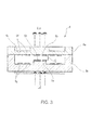
- FIGs. 1A to 1C are block diagrams showing a schematic configuration of a spectroscopic image capturing apparatus according to a first embodiment.
- a spectroscopic image capturing apparatus 100 according to the first embodiment includes an image acquisition unit 30 (hereinafter referred to as a spectroscopic camera unit 30), which includes a light source section 10 and an imaging section 20, and a processing control unit 40, which controls the light source section 10 and performs image processing on an image produced by the imaging section 20, as shown in Fig. 1A .
- a spectroscopic camera unit 30 which includes a light source section 10 and an imaging section 20, and a processing control unit 40, which controls the light source section 10 and performs image processing on an image produced by the imaging section 20, as shown in Fig. 1A .
- the light source section 10 includes a light source portion 1, which includes a lamp that works as a light source, a first lens group 2, which converts lamp light La from the light source portion 1 into parallelized light Lb, and a first polarizing plate 3, which forms a first polarizer and polarizes the parallelized light Lb from the first lens group 2 into linearly polarized light Lp, as shown in Fig. 1B .
- the lamp light La emitted from the light source portion 1 passes through the first lens group 2 and the first polarizing plate 3 and exits in the form of the linearly polarized light Lp toward an object M.
- the first lens group 2, which is drawn in the form of a single lens in Fig. 1B is formed of a combination of a plurality of lenses.
- the linearly polarized light Lp outputted from the light source section 10, the wavelength of which is selected as appropriate in accordance with what parameter of the object M is analyzed, is preferably infrared light, for example, when the object M is a food product and internal components thereof are analyzed. Visible light can alternatively be used when the color of the surface of the object M is measured.
- the light source portion 1 is a tungsten lamp, an infrared LED, or any other suitable light source.
- the imaging section 20 includes a second polarizing plate 4, which forms a second polarizer and polarizes reflected light Lr from the object M into linearly polarized light Lc, a second lens group 5, which collects the linearly polarized light Lc into parallelized light Ld, an optical filter 6, which filters the parallelized light Ld from the second lens group 5 into analyzed light Le having a desired wavelength, and an imaging device 7, which serves as an imaging unit and captures an image formed of the analyzed light Le having a desired wavelength and having passed through the optical filter 6, as shown in Fig. 1C .
- the second lens group 5, which is drawn in the form of a single lens in Fig. 1C is formed of a combination of a plurality of lenses.
- Fig. 2A is a conceptual diagram schematically showing the relationship between the light outputted from the light source section 10 and the light incident on the imaging section 20.
- the parallelized light Lb formed from the light from the light source portion 1 that has passed through the first lens group 2 is a combination of light fluxes oscillating in all directions although they form parallelized light as a whole, as shown in Fig. 2A .
- the parallelized light Lb after it passes through the first polarizing plate 3, which produces light polarized in a linear oscillation direction P1, forms the linearly polarized light Lp polarized in the linear oscillation direction P1, which is projected toward the obj ect M.
- the linearly polarized light Lp projected onto the object M is light in the wavelength region of infrared light described above, the linearly polarized light Lp that impinges on the surface of the object M further reaches the interior thereof.
- the linearly polarized light Lp having reached the interior of the object M is repeatedly reflected in the interior of the object M and therefore depolarized, and the depolarized light is reflected in the form of reflected light Lr, which is a combination of light fluxes oscillating in all directions.
- the reflected light Lr contains polarized reflected light Lr P , which is the linearly polarized light Lp specularly reflected off the surface of the object M.
- the polarized reflected light Lr P which has been specularly reflected, has a higher intensity in the intensity distribution of the light projected onto the imaging device 7 shown in Fig. 1C , that is, the light intensity distribution of the reflected light Lr, than the light intensities in the other region containing no specular reflection, as shown in Fig. 2B .
- the presence of a portion having a high light intensity due to the specular reflection produces a large error in a spectroscopic image showing internal components of the object M.
- the second polarizing plate 4 provided in the imaging section 20, which receives the reflected light Lr is so disposed that the polarization axis of the second polarizing plate 4 is oriented in a polarization direction P2, which is perpendicular to the polarization axis of the first polarizer plate 3, that is, the polarization direction P1, as shown in Fig. 2A .
- the linearly polarized light Lc free of the polarized reflected light Lr P which is the specular reflection component, is produced.
- a spectroscopic image produced by the linearly polarized light Lc having passed through the second lens group 5 and the optical filter 6, which is the analyzed light Le, can thus be an image having a small amount of significant deviation in the light intensity distribution.
- a spectroscopic image from which a more accurate analysis result is derived can therefore be produced.
- the incident light having passed through the second polarizing plate 4 and formed the linearly polarized light Lc is collected by the second lens group 5 to form the parallelized light Ld, which is guided to the optical filter 6, as shown in Fig. 1C .
- the optical filter 6 is described based on a variable wavelength optical filter.
- a variable wavelength optical filter is referred to as what is called an etalon filter, and Fig. 3 is a schematic cross-sectional view of an etalon filter.
- the optical filter 6, which is a variable wavelength optical filter is formed by bonding a first substrate 6a and a second substrate 6b to each other, as shown in Fig. 3 .
- Each of the first substrate 6a and the second substrate 6b is formed of a transparent member made, for example, of soda glass, crystalline glass, quartz glass, lead glass, potassium glass, borosilicate glass, no-alkali glass, and a variety of other types of glass or quartz and other light-transmissive materials.
- a first reflection film 6c is formed on a surface of the first substrate 6a in a central portion thereof that faces the second substrate 6b, and a second reflection film 6e is formed on the upper surface of an internal protrusion 6d of the second substrate 6b that faces the first reflection film 6c.
- Each of the reflection films 6c and 6e is formed of a dielectric multilayer film produced by alternately stacking a high-refractive-index layer and a low-refractive-index layer multiple times.
- the high-refractive-index layer of the dielectric multilayer film is made, for example, of titanium dioxide (TiO 2 ), tantalum pentoxide (Ta 2 O 5 ), and niobium pentoxide (Nb 2 O 5 ), and the low-refractive-index layer of the dielectric multilayer film is made, for example, of magnesium fluoride (MgF 2 ) and silicon dioxide (SiO 2 ).
- the high-refractive-index layer is made, for example, of aluminum oxide (Al 2 O 3 ), hafnium oxide (HfO 2 ), zirconium dioxide (ZrO 2 ), and thorium oxide (ThO 2 ), and the low-refractive-index layer is made, for example, of magnesium fluoride (MgF 2 ) and silicon dioxide (SiO 2 ).
- Each of the reflection films 6c and 6e may alternatively be formed of a metal-based reflection film made, for example, of silver.
- Annular first electrodes 6f are formed around the outer circumference of the first reflection film 6c on the first substrate 6a.
- Second electrodes 6g, which face the first electrodes 6f, are formed on the second substrate 6b.
- a current is allowed to flow through the first electrodes 6f and the second electrodes 6g under the control of the processing control unit 40 shown in Fig. 1A so that a force that attracts the first electrodes 6f and the second electrodes 6g to each other is produced in accordance with the magnitude of the current, the direction thereof, and other factors.
- the area of the first substrate 6a where the first electrodes 6f are formed forms an annular thin portion 6h, which is bent by the attractive force.
- the distance G (hereinafter referred to as a gap G) between the first reflection film 6c and the second reflection film 6e are arbitrarily changed so that multiple beam interference occurs in the gap G and the incident parallelized light Ld is so filtered that the analyzed light Le having a predetermined wavelength is outputted.
- the analyzed light Le is converted into an image signal by the imaging device 7 formed, for example, of a CCD (charge coupled device) image sensor, as shown in Fig. 1C .
- the optical filter 6 is driven to separate the analyzed light Le into N light fluxes having wavelengths different from each other, that is, analyzed light fluxes Le 1 , Le 2 , ..., Le N , and image signals based on the analyzed light fluxes Le 1 , Le 2 , ..., Le N are sent to the processing control unit 40. Predetermined analyzed images (data) are thus created.
- the N analyzed light fluxes Le 1 , Le 2 , ..., Le N are produced from the reflected light Lr by extracting light fluxes having wavelengths characterized by primary components of the object M and undergo image processing in the processing control unit 40.
- the resultant spectroscopic images are outputted as data.
- the spectroscopic image capturing apparatus 100 can produce the analyzed light Le free of the specular reflection component from the object M based on the configuration in which the polarization direction of the first polarizing plate 3 provided in the light source section 10 and the polarization direction of the second polarizing plate 4 provided in the imaging section 20 are perpendicular to each other. An image for precise spectroscopic analysis can therefore be produced. Since the configuration further allows specular reflection to be readily removed, the apparatus can be so configured that the angle ⁇ between the optical axis of the linearly polarized light Lp, which is outgoing light, and the optical axis of the reflected light Lr shown in Fig.
- the spectroscopic camera unit 30 can therefore be further reduced, as shown in Fig. 1A .
- the spectroscopic camera unit 30 can be held by hand, as a typical digital camera, for analysis imaging. Further, integrating the processing control unit 40 with the spectroscopic camera unit 30 can even make the spectroscopic image capturing apparatus 100 portable.
- the same components as those of the spectroscopic image capturing apparatus 100 according to the first embodiment have the same reference characters and no description of the same components will be made in some cases.
- Figs. 4A to 4C show the spectroscopic image capturing apparatus 200 according to the second embodiment.
- Fig. 4A is a block diagram showing a schematic configuration of the apparatus.
- Fig. 4B is a block diagram showing the configuration of a light source section in the apparatus.
- Fig. 4C is a block diagram showing the configuration of an imaging section in the apparatus.
- the spectroscopic image capturing apparatus 200 has the same configuration as that of the spectroscopic image capturing apparatus 100 described in the first embodiment as shown in Fig.
- a light source section 210 and an imaging section 220 provided in a spectroscopic camera unit 230 include a first circularly polarizing plate 203 and a second circularly polarizing plate 204 for producing circular polarization respectively, as shown in Figs. 4B and 4C .
- the light source section 210 in which the light emitted from the light source portion 1 is circularly polarized by the first circularly polarizing plate 203, outputs circularly polarized light Lp s .
- the outputted circularly polarized light Lp s is reflected off an object M and forms reflected light Lr, which is separated into right-handed circularly polarized light and left-handed circularly polarized light by the second circularly polarizing plate 204.
- the second circularly polarizing plate 204 transmits only one of the two types of circularly polarized light, circularly polarized light Lc s , which is collected by the second lens group 5, and the resultant parallelized light Ld is guided to the optical filter 6.
- the optical filter 6 produces analyzed light Le having a desired wavelength, from which the imaging device 7 produces image data.
- Each of the circularly polarizing plates 203 and 204 can be a polarizing plate formed of a linearly polarizing plate to which a ⁇ /4 retardation film is bonded with its axis inclined to the linearly polarizing plate by 45 degrees. The thus formed polarizing plate can produce and output circularly polarized light.
- Figs. 5A to 5D are conceptual diagrams schematically showing the relationship between the light outputted from the light source section 210 and the light incident on the imaging section 220.
- the parallelized light Lb having passed through the first lens group 2 passes through the first circularly polarizing plate 203 including the ⁇ /4 retardation film so that the parallelized light Lb is converted into the circularly polarized light Lp s , which is outputted and applied to the object M.
- the circularly polarized light Lp s is so polarized that it rotates in the left-handed rotation direction as shown in Fig. 5B viewed in the direction of the arrow Wp along the optical axis of the circularly polarized light Lp s shown in Fig. 5A .
- the circularly polarized light Lp s when applied to the object M, reaches the interior of the object M and is reflected off the object M to form the reflected light Lr. Since the circularly polarized light Lp s is depolarized in the interior of the object M, the reflected light Lr is a combination of light fluxes oscillating in all directions.
- the reflected light Lr contains circularly polarized reflected light Lr s , which is the circularly polarized light Lp s specularly reflected off the surface of the object M.
- the circularly polarized reflected light Lr s is so reflected that it rotates in the right-handed rotation direction as shown in Fig.
- the specularly reflected light Lr s forms the circularly polarized light Lr s rotating in the direction opposite to the rotation direction of the outputted circularly polarized light Lp s .
- the reflected light Lr is incident on the second circularly polarizing plate 204.
- the second circularly polarizing plate 204 polarizes the reflected light Lr into circularly polarized light Lc s rotating in the left-handed rotation direction as shown in Fig. 5D viewed in the direction of the arrow Wr along the optical axis of the reflected light Lr shown in Fig. 5A .
- the circularly polarized reflected light Lr s contained in the reflected light Lr incident on the second circularly polarizing plate 204 is therefore absorbed by the second circularly polarizing plate 204, which polarizes light incident thereon into polarized light rotating in the direction opposite to the rotation direction of the circularly polarized reflected light Lr s .
- the analyzed light Le free of the specularly reflected component from the object M can be produced by setting the rotation direction of the circularly polarized light outputted from the first circularly polarizing plate 203 provided in the light source section 210 to be the same as the rotation direction of the circularly polarized light outputted from the second circularly polarizing plate 204 provided in the imaging section 220.
- An image for precise spectroscopic analysis can therefore be produced.
- the spectroscopic image capturing apparatus 200 according to the second embodiment has been described with reference to the case where the circularly polarized light Lp s rotates in the left-handed rotation direction in Fig.
- the circularly polarized reflected light Lr s rotates in the right-handed rotation direction in Fig. 5C
- the circularly polarized light Lc s rotates in the left-handed rotation direction in Fig. 5D .
- the rotation directions are not limited to those described above, and the circularly polarized light Lp s and the circularly polarized light Lc s only need to rotate in the same rotation direction.
- the first polarizing plate 3 in the spectroscopic image capturing apparatus 100 may alternatively be a polarization conversion element, such as a PSB (polarized beam splitter).
- a polarization conversion element reduces the amount of decrease in the amount of outputted light Lp from the light source section 10, whereby the brightness, contrast, and other image-quality-related parameters of an analyzed image can be increased.
- a spectroscopic image capturing apparatus capable of performing more accurate analysis can thus be provided.
Landscapes
- Physics & Mathematics (AREA)
- Spectroscopy & Molecular Physics (AREA)
- General Physics & Mathematics (AREA)
- Health & Medical Sciences (AREA)
- Life Sciences & Earth Sciences (AREA)
- Chemical & Material Sciences (AREA)
- Analytical Chemistry (AREA)
- Biochemistry (AREA)
- General Health & Medical Sciences (AREA)
- Immunology (AREA)
- Pathology (AREA)
- Investigating Or Analysing Materials By Optical Means (AREA)
- Spectrometry And Color Measurement (AREA)
- Color Television Image Signal Generators (AREA)
- Studio Devices (AREA)
Abstract
Description
- The present invention relates to a spectroscopic image capturing apparatus.
- As a method for acquiring information on the component or content of an object while keeping the object intact, there is a widely used method for capturing spectral image data on the object and analyzing the data to produce, for example, component information. For example, the method for acquiring spectral data on a specific portion of an object described in
JP-A-2000-329617 JP-A-2000-329617 - Further,
JP-A-2009-33222 - In recent years, however, trends of maintaining health, ensuring food safety, and other requirements increasingly demand a compact food checker and other devices for measuring components, sugar content, and other parameters of a food product. The spectroscopic image input system disclosed in
JP-A-2000-329617 JP-A-2009-33222 - An advantage of some aspects of the invention is to provide a spectroscopic image capturing apparatus capable of suppression of an effect of specular reflection and accurate spectroscopic analysis of an object.
- The invention can be implemented as the following forms or application examples.
- A spectroscopic image capturing apparatus according to this application example includes a light source section and an imaging section. The light source section includes a light source portion, a first lens group, and a first polarizer, and the imaging section includes a second polarizer, a second lens group, an optical filter, and an imaging unit.
- According to the spectroscopic image capturing apparatus of this application example, when polarized light outputted from the first polarizer provided in the light source section is projected onto an object to be analyzed in terms of component, the polarized light reaches the interior of the object, and light reflected off internal components is the outputted light that is depolarized. On the other hand, light specularly reflected off the surface of the object is the outputted polarized light with its polarization maintained. The reflected light depolarized by the internal components of the object and the polarized light specularly reflected off the surface of the object, the mixture of which forms analyzed light, are incident on the imaging section. The second polarizer provided in the imaging section absorbs the polarized light in the incident analyzed light, and only the reflected light depolarized by the internal components of the object reaches the imaging unit. As a result, the imaging unit can receive analyzed light free of the component specularly reflected off the surface of the object, whereby the spectroscopic image capturing apparatus can form an image of the object for accurate spectroscopic analysis.
- In the application example described above, each of the first polarizer and the second polarizer includes a linearly polarizing portion, and the first polarizer and the second polarizer are so disposed that the polarization direction of linearly polarized light produced by the first polarizer and the polarization direction of linearly polarized light produced by the second polarizer are perpendicular to each other.
- The term "perpendicular" used in the application example described above does not mean exact 90-degree intersection but accepts a predetermined angular range around a target value of 90 degrees at least in consideration of positional precision in typical apparatus assembly or variations of parts themselves. According to the application example described above, since each of the first polarizer and the second polarizer is a linearly polarizing portion that polarizes light incident thereon into linearly polarized light, the amount of change (shift) in the polarization of the light specularly reflected off the surface of the object is small, whereby the imaging section can more reliably remove the specularly reflected light and the spectroscopic image capturing apparatus can hence form an image of the object for accurate spectroscopic analysis.
- In the application example described above, each of the linearly polarizing portions is a linearly polarizing plate.
- According to the application example described above, the spectroscopic image capturing apparatus can be simply configured, and the polarization axes of the first polarizer and the second polarizer can be readily adjusted with respect to each other.
- In the application example described above, each of the first polarizer and the second polarizer include a circularly polarizing portion, and the first polarizer and the second polarizer are so disposed that the rotation direction of circularly polarized light produced by the first polarizer and the rotation direction of circularly polarized light produced by the second polarizer are the same direction.
- According to the application example described above, since each of the first polarizer and the second polarizer is a circularly polarizing portion that polarizes light incident thereon into circularly polarized light, the amount of change (shift) in the polarization of the light specularly reflected off the surface of the object is small, whereby using circularly polarized light allows the imaging section to more reliably remove the specularly reflected light even when the positioning of the second polarizer around the optical axis is shifted and the spectroscopic image capturing apparatus can hence form an image of the object for accurate spectroscopic analysis.
- In the application example described above, each of the circularly polarizing portions includes a λ/4 retardation film.
- According to the application example described above, since combining a λ/4 retardation film with a polarizing plate readily allows polarized light to be produced and the circularly polarizing portions of the first polarizer and the second polarizer can include the same circularly polarizing portion, the directions of circularly polarized light can be readily oriented in the same direction in the spectroscopic image capturing apparatus.
- In the application example described above, the optical filter is a variable wavelength optical filter.
- According to the application example described above, using a variable wavelength optical filter, which allows selection of a wavelength region within which a spectroscopic image of a desired component from a variety of components contained in the object is acquired, allows a single spectroscopic image capturing apparatus to acquire a desired spectroscopic image.
- A spectroscopic image capturing apparatus according to this application example includes a light source, a first polarizer, a second polarizer, an optical filter, and an imaging unit. The first polarizer is disposed in a first optical path between the light source and an obj ect to be imaged, and the second polarizer is disposed in a second optical path between the object to be imaged and the imaging unit.
- According to the spectroscopic image capturing apparatus of this application example, when polarized light outputted from the first polarizer provided in the light source section is projected onto an object to be analyzed in terms of component, the polarized light reaches the interior of the object, and light reflected off internal components is the outputted light that is depolarized. On the other hand, light specularly reflected off the surface of the object is the outputted polarized light with its polarization maintained. The reflected light depolarized by the internal components of the object and the polarized light specularly reflected off the surface of the object, the mixture of which forms analyzed light, are incident on the imaging unit. The second polarizer provided in the imaging section absorbs the polarized light in the incident analyzed light, and only the reflected light depolarized by the internal components of the object reaches the imaging unit. As a result, the imaging unit can receive analyzed light free of the component specularly reflected off the surface of the object, whereby the spectroscopic image capturing apparatus can form an image of the obj ect for accurate spectroscopic analysis.
- In the application example described above, each of the first polarizer and the second polarizer include a linearly polarizing portion, and the first polarizer and the second polarizer are so disposed that the polarization direction of linearly polarized light produced by the first polarizer and the polarization direction of linearly polarized light produced by the second polarizer are perpendicular to each other.
- The term "perpendicular" used in the application example described above also does not mean exact 90-degree intersection but accepts a predetermined angular range around a target value of 90 degrees at least in consideration of positional precision in typical apparatus assembly or variations of parts themselves. According to the application example described above, since each of the first polarizer and the second polarizer is a linearly polarizing portion that polarizes light incident thereon into linearly polarized light, the amount of change (shift) in the polarization of the light specularly reflected off the surface of the object is small, whereby the imaging unit can more reliably remove the specularly reflected light and the spectroscopic image capturing apparatus can hence form an image of the object for accurate spectroscopic analysis.
- The invention will be described with reference to the accompanying drawings, wherein like numbers reference like elements.
-
Figs. 1A to 1C show a spectroscopic image capturing apparatus according to a first embodiment:Fig. 1A is a block diagram of a schematic configuration of the apparatus;Fig. 1B is a block diagram of a light source section in the apparatus; andFig. 1C is a block diagram of an imaging section in the apparatus. -
Figs. 2A and 2B describe the spectroscopic image capturing apparatus according to the first embodiment:Fig. 2A is a conceptual diagram schematically showing the relationship between light outputted from the light source section and light incident on the imaging section; andFig. 2B schematically shows a light intensity distribution for describing specular reflection. -
Fig. 3 is a cross-sectional view of a schematic configuration of an optical filter provided in the spectroscopic image capturing apparatus according to the first embodiment. -
Figs. 4A to 4C show a spectroscopic image capturing apparatus according to a second embodiment:Fig. 4A is a block diagram of a schematic configuration of the apparatus;Fig. 4B is a block diagram of a light source section in the apparatus; andFig. 4C is a block diagram of an imaging section in the apparatus. -
Figs. 5A to 5D describe the spectroscopic image capturing apparatus according to the second embodiment:Fig. 5A is a conceptual diagram schematically showing the relationship between light outputted from a light source section and light incident on an imaging section; andFigs. 5B to 5D describe the direction of circularly polarized light. - Embodiments according to the invention will be described below with reference to the drawings.
-
Figs. 1A to 1C are block diagrams showing a schematic configuration of a spectroscopic image capturing apparatus according to a first embodiment. A spectroscopicimage capturing apparatus 100 according to the first embodiment includes an image acquisition unit 30 (hereinafter referred to as a spectroscopic camera unit 30), which includes alight source section 10 and animaging section 20, and aprocessing control unit 40, which controls thelight source section 10 and performs image processing on an image produced by theimaging section 20, as shown inFig. 1A . - The
light source section 10 includes a light source portion 1, which includes a lamp that works as a light source, afirst lens group 2, which converts lamp light La from the light source portion 1 into parallelized light Lb, and a firstpolarizing plate 3, which forms a first polarizer and polarizes the parallelized light Lb from thefirst lens group 2 into linearly polarized light Lp, as shown inFig. 1B . The lamp light La emitted from the light source portion 1 passes through thefirst lens group 2 and the firstpolarizing plate 3 and exits in the form of the linearly polarized light Lp toward an object M. Thefirst lens group 2, which is drawn in the form of a single lens inFig. 1B , is formed of a combination of a plurality of lenses. - The linearly polarized light Lp outputted from the
light source section 10, the wavelength of which is selected as appropriate in accordance with what parameter of the object M is analyzed, is preferably infrared light, for example, when the object M is a food product and internal components thereof are analyzed. Visible light can alternatively be used when the color of the surface of the object M is measured. When infrared light is used, the light source portion 1 is a tungsten lamp, an infrared LED, or any other suitable light source. - The
imaging section 20 includes a second polarizing plate 4, which forms a second polarizer and polarizes reflected light Lr from the object M into linearly polarized light Lc, asecond lens group 5, which collects the linearly polarized light Lc into parallelized light Ld, anoptical filter 6, which filters the parallelized light Ld from thesecond lens group 5 into analyzed light Le having a desired wavelength, and animaging device 7, which serves as an imaging unit and captures an image formed of the analyzed light Le having a desired wavelength and having passed through theoptical filter 6, as shown inFig. 1C . Thesecond lens group 5, which is drawn in the form of a single lens inFig. 1C , is formed of a combination of a plurality of lenses. -
Fig. 2A is a conceptual diagram schematically showing the relationship between the light outputted from thelight source section 10 and the light incident on theimaging section 20. The parallelized light Lb formed from the light from the light source portion 1 that has passed through thefirst lens group 2 is a combination of light fluxes oscillating in all directions although they form parallelized light as a whole, as shown inFig. 2A . The parallelized light Lb, after it passes through the firstpolarizing plate 3, which produces light polarized in a linear oscillation direction P1, forms the linearly polarized light Lp polarized in the linear oscillation direction P1, which is projected toward the obj ect M. - Since the linearly polarized light Lp projected onto the object M is light in the wavelength region of infrared light described above, the linearly polarized light Lp that impinges on the surface of the object M further reaches the interior thereof. The linearly polarized light Lp having reached the interior of the object M is repeatedly reflected in the interior of the object M and therefore depolarized, and the depolarized light is reflected in the form of reflected light Lr, which is a combination of light fluxes oscillating in all directions. The reflected light Lr, however, contains polarized reflected light LrP, which is the linearly polarized light Lp specularly reflected off the surface of the object M. The polarized reflected light LrP, which has been specularly reflected, has a higher intensity in the intensity distribution of the light projected onto the
imaging device 7 shown inFig. 1C , that is, the light intensity distribution of the reflected light Lr, than the light intensities in the other region containing no specular reflection, as shown inFig. 2B . The presence of a portion having a high light intensity due to the specular reflection produces a large error in a spectroscopic image showing internal components of the object M. - To address the problem, the second polarizing plate 4 provided in the
imaging section 20, which receives the reflected light Lr, is so disposed that the polarization axis of the second polarizing plate 4 is oriented in a polarization direction P2, which is perpendicular to the polarization axis of thefirst polarizer plate 3, that is, the polarization direction P1, as shown inFig. 2A . As a result, the linearly polarized light Lc free of the polarized reflected light LrP, which is the specular reflection component, is produced. A spectroscopic image produced by the linearly polarized light Lc having passed through thesecond lens group 5 and theoptical filter 6, which is the analyzed light Le, can thus be an image having a small amount of significant deviation in the light intensity distribution. A spectroscopic image from which a more accurate analysis result is derived can therefore be produced. - The incident light having passed through the second polarizing plate 4 and formed the linearly polarized light Lc is collected by the
second lens group 5 to form the parallelized light Ld, which is guided to theoptical filter 6, as shown inFig. 1C . In this embodiment, theoptical filter 6 is described based on a variable wavelength optical filter. A variable wavelength optical filter is referred to as what is called an etalon filter, andFig. 3 is a schematic cross-sectional view of an etalon filter. Theoptical filter 6, which is a variable wavelength optical filter, is formed by bonding a first substrate 6a and a second substrate 6b to each other, as shown inFig. 3 . Each of the first substrate 6a and the second substrate 6b is formed of a transparent member made, for example, of soda glass, crystalline glass, quartz glass, lead glass, potassium glass, borosilicate glass, no-alkali glass, and a variety of other types of glass or quartz and other light-transmissive materials. - A first reflection film 6c is formed on a surface of the first substrate 6a in a central portion thereof that faces the second substrate 6b, and a second reflection film 6e is formed on the upper surface of an internal protrusion 6d of the second substrate 6b that faces the first reflection film 6c. Each of the reflection films 6c and 6e is formed of a dielectric multilayer film produced by alternately stacking a high-refractive-index layer and a low-refractive-index layer multiple times. To use the
optical filter 6 in a visible or infrared wavelength region, the high-refractive-index layer of the dielectric multilayer film is made, for example, of titanium dioxide (TiO2), tantalum pentoxide (Ta2O5), and niobium pentoxide (Nb2O5), and the low-refractive-index layer of the dielectric multilayer film is made, for example, of magnesium fluoride (MgF2) and silicon dioxide (SiO2). To use theoptical filter 6 in an ultraviolet wavelength region, the high-refractive-index layer is made, for example, of aluminum oxide (Al2O3), hafnium oxide (HfO2), zirconium dioxide (ZrO2), and thorium oxide (ThO2), and the low-refractive-index layer is made, for example, of magnesium fluoride (MgF2) and silicon dioxide (SiO2). Each of the reflection films 6c and 6e may alternatively be formed of a metal-based reflection film made, for example, of silver. - Annular first electrodes 6f are formed around the outer circumference of the first reflection film 6c on the first substrate 6a. Second electrodes 6g, which face the first electrodes 6f, are formed on the second substrate 6b. A current is allowed to flow through the first electrodes 6f and the second electrodes 6g under the control of the
processing control unit 40 shown inFig. 1A so that a force that attracts the first electrodes 6f and the second electrodes 6g to each other is produced in accordance with the magnitude of the current, the direction thereof, and other factors. The area of the first substrate 6a where the first electrodes 6f are formed forms an annular thin portion 6h, which is bent by the attractive force. The distance G (hereinafter referred to as a gap G) between the first reflection film 6c and the second reflection film 6e are arbitrarily changed so that multiple beam interference occurs in the gap G and the incident parallelized light Ld is so filtered that the analyzed light Le having a predetermined wavelength is outputted. - The analyzed light Le is converted into an image signal by the
imaging device 7 formed, for example, of a CCD (charge coupled device) image sensor, as shown inFig. 1C . Specifically, theoptical filter 6 is driven to separate the analyzed light Le into N light fluxes having wavelengths different from each other, that is, analyzed light fluxes Le1, Le2, ..., LeN, and image signals based on the analyzed light fluxes Le1, Le2, ..., LeN are sent to theprocessing control unit 40. Predetermined analyzed images (data) are thus created. The N analyzed light fluxes Le1, Le2, ..., LeN are produced from the reflected light Lr by extracting light fluxes having wavelengths characterized by primary components of the object M and undergo image processing in theprocessing control unit 40. The resultant spectroscopic images are outputted as data. - As described above, the spectroscopic
image capturing apparatus 100 according to the first embodiment can produce the analyzed light Le free of the specular reflection component from the object M based on the configuration in which the polarization direction of the firstpolarizing plate 3 provided in thelight source section 10 and the polarization direction of the second polarizing plate 4 provided in theimaging section 20 are perpendicular to each other. An image for precise spectroscopic analysis can therefore be produced. Since the configuration further allows specular reflection to be readily removed, the apparatus can be so configured that the angle θ between the optical axis of the linearly polarized light Lp, which is outgoing light, and the optical axis of the reflected light Lr shown inFig. 2A is set at an acute angle close to zero degrees, which causes the apparatus to receive a large amount of specular reflection. The size of thespectroscopic camera unit 30 can therefore be further reduced, as shown inFig. 1A . For example, thespectroscopic camera unit 30 can be held by hand, as a typical digital camera, for analysis imaging. Further, integrating theprocessing control unit 40 with thespectroscopic camera unit 30 can even make the spectroscopicimage capturing apparatus 100 portable. - As a second embodiment, a description will be made of a spectroscopic
image capturing apparatus 200 different from the spectroscopicimage capturing apparatus 100 according to the first embodiment in terms of thefirst polarizer plate 3 and the second polarizer plate 4 provided therein. In the spectroscopicimage capturing apparatus 200 according to the second embodiment, the same components as those of the spectroscopicimage capturing apparatus 100 according to the first embodiment have the same reference characters and no description of the same components will be made in some cases. -
Figs. 4A to 4C show the spectroscopicimage capturing apparatus 200 according to the second embodiment.Fig. 4A is a block diagram showing a schematic configuration of the apparatus.Fig. 4B is a block diagram showing the configuration of a light source section in the apparatus.Fig. 4C is a block diagram showing the configuration of an imaging section in the apparatus. The spectroscopicimage capturing apparatus 200 has the same configuration as that of the spectroscopicimage capturing apparatus 100 described in the first embodiment as shown inFig. 4A , but alight source section 210 and animaging section 220 provided in aspectroscopic camera unit 230 include a firstcircularly polarizing plate 203 and a secondcircularly polarizing plate 204 for producing circular polarization respectively, as shown inFigs. 4B and 4C . Thelight source section 210, in which the light emitted from the light source portion 1 is circularly polarized by the firstcircularly polarizing plate 203, outputs circularly polarized light Lps. The outputted circularly polarized light Lps is reflected off an object M and forms reflected light Lr, which is separated into right-handed circularly polarized light and left-handed circularly polarized light by the secondcircularly polarizing plate 204. The secondcircularly polarizing plate 204 transmits only one of the two types of circularly polarized light, circularly polarized light Lcs, which is collected by thesecond lens group 5, and the resultant parallelized light Ld is guided to theoptical filter 6. Theoptical filter 6 produces analyzed light Le having a desired wavelength, from which theimaging device 7 produces image data. Each of the circularlypolarizing plates -
Figs. 5A to 5D are conceptual diagrams schematically showing the relationship between the light outputted from thelight source section 210 and the light incident on theimaging section 220. As shown inFig. 5A , the parallelized light Lb having passed through thefirst lens group 2 passes through the firstcircularly polarizing plate 203 including the λ/4 retardation film so that the parallelized light Lb is converted into the circularly polarized light Lps, which is outputted and applied to the object M. In this embodiment, the circularly polarized light Lps is so polarized that it rotates in the left-handed rotation direction as shown inFig. 5B viewed in the direction of the arrow Wp along the optical axis of the circularly polarized light Lps shown inFig. 5A . - The circularly polarized light Lps, when applied to the object M, reaches the interior of the object M and is reflected off the object M to form the reflected light Lr. Since the circularly polarized light Lps is depolarized in the interior of the object M, the reflected light Lr is a combination of light fluxes oscillating in all directions. The reflected light Lr, however, contains circularly polarized reflected light Lrs, which is the circularly polarized light Lps specularly reflected off the surface of the object M. In this embodiment, the circularly polarized reflected light Lrs is so reflected that it rotates in the right-handed rotation direction as shown in
Fig. 5C viewed in the direction of the arrow Wr along the optical axis of the reflected light Lr shown inFig. 5A . That is, the specularly reflected light Lrs forms the circularly polarized light Lrs rotating in the direction opposite to the rotation direction of the outputted circularly polarized light Lps. - The reflected light Lr is incident on the second
circularly polarizing plate 204. The secondcircularly polarizing plate 204 polarizes the reflected light Lr into circularly polarized light Lcs rotating in the left-handed rotation direction as shown inFig. 5D viewed in the direction of the arrow Wr along the optical axis of the reflected light Lr shown inFig. 5A . The circularly polarized reflected light Lrs contained in the reflected light Lr incident on the secondcircularly polarizing plate 204 is therefore absorbed by the secondcircularly polarizing plate 204, which polarizes light incident thereon into polarized light rotating in the direction opposite to the rotation direction of the circularly polarized reflected light Lrs. - As described above, in the spectroscopic
image capturing apparatus 200 according to the second embodiment, the analyzed light Le free of the specularly reflected component from the object M can be produced by setting the rotation direction of the circularly polarized light outputted from the firstcircularly polarizing plate 203 provided in thelight source section 210 to be the same as the rotation direction of the circularly polarized light outputted from the secondcircularly polarizing plate 204 provided in theimaging section 220. An image for precise spectroscopic analysis can therefore be produced. The spectroscopicimage capturing apparatus 200 according to the second embodiment has been described with reference to the case where the circularly polarized light Lps rotates in the left-handed rotation direction inFig. 5B , the circularly polarized reflected light Lrs rotates in the right-handed rotation direction inFig. 5C , and the circularly polarized light Lcs rotates in the left-handed rotation direction inFig. 5D . The rotation directions are not limited to those described above, and the circularly polarized light Lps and the circularly polarized light Lcs only need to rotate in the same rotation direction. - The first
polarizing plate 3 in the spectroscopicimage capturing apparatus 100 according to the first embodiment described above may alternatively be a polarization conversion element, such as a PSB (polarized beam splitter). Using a polarization conversion element reduces the amount of decrease in the amount of outputted light Lp from thelight source section 10, whereby the brightness, contrast, and other image-quality-related parameters of an analyzed image can be increased. A spectroscopic image capturing apparatus capable of performing more accurate analysis can thus be provided.
Claims (11)
- A spectroscopic image capturing apparatus comprising:a light source section; andan imaging section,wherein the light source section includes a light source portion, a first lens group, and a first polarizer, andthe imaging section includes a second polarizer, a second lens group, an optical filter, and an imaging unit.
- The spectroscopic image capturing apparatus according to claim 1,
wherein each of the first polarizer and the second polarizer includes a linearly polarizing portion, and
the first polarizer and the second polarizer are so disposed that the polarization direction of linearly polarized light produced by the first polarizer and the polarization direction of linearly polarized light produced by the second polarizer are perpendicular to each other. - The spectroscopic image capturing apparatus according to claim 2,
wherein each of the linearly polarizing portions is a linearly polarizing plate. - The spectroscopic image capturing apparatus according to any one of the preceding claims,
wherein each of the first polarizer and the second polarizer includes a circularly polarizing portion, and
the first polarizer and the second polarizer are so disposed that the rotation direction of circularly polarized light produced by the first polarizer and the rotation direction of circularly polarized light produced by the second polarizer are the same direction. - The spectroscopic image capturing apparatus according to claim 4,
wherein each of the circularly polarizing portions includes a λ/4 retardation film. - The spectroscopic image capturing apparatus according to any one of the preceding claims,
wherein the optical filter is a variable wavelength optical filter. - A spectroscopic image capturing apparatus comprising:a light source;a first polarizer;a second polarizer;an optical filter; andan imaging unit,wherein the first polarizer is disposed in an optical path between the light source and an object to be imaged, andthe second polarizer is disposed in an optical path between the object to be imaged and the imaging unit.
- The spectroscopic image capturing apparatus according to claim 7,
wherein each of the first polarizer and the second polarizer includes a linearly polarizing portion, and
the first polarizer and the second polarizer are so disposed that the polarization direction of linearly polarized light produced by the first polarizer and the polarization direction of linearly polarized light produced by the second polarizer are perpendicular to each other. - A spectroscopic image capturing apparatus comprising:a light source portion including a light source and a first polarizer; andan imaging portion including a second polarizer, an optical filter, and a light receiving portion,wherein the first polarizer and the second polarizer are so disposed that the polarization direction of polarized light produced by the first polarizer and the polarization direction of polarized light produced by the second polarizer are perpendicular to each other.
- A spectroscopic image capturing apparatus comprising:a light source that irradiates an object to be imaged with linearly polarized light; anda linearly polarizing plate in a light receiving portion on which light reflected off the object to be imaged is incident,wherein the linearly polarizing plate is so disposed that the polarization direction of polarized light produced by the linearly polarizing plate is perpendicular to the polarization direction of the light from the light source.
- A spectroscopic image capturing apparatus comprising:a light source that irradiates an object to be imaged with circularly polarized light; anda linearly polarizing plate and a λ/4 retardation film in a light receiving portion on which light reflected off the object to be imaged is incident,wherein the rotation direction of circularly polarized light produced by the linearly polarizing plate and the λ/4 retardation film in the light receiving portion is the same as the rotation direction of circularly polarized light emitted from the light source.
Applications Claiming Priority (1)
| Application Number | Priority Date | Filing Date | Title |
|---|---|---|---|
| JP2012148202A JP2014010093A (en) | 2012-07-02 | 2012-07-02 | Spectral image pickup device |
Publications (1)
| Publication Number | Publication Date |
|---|---|
| EP2682723A1 true EP2682723A1 (en) | 2014-01-08 |
Family
ID=48746319
Family Applications (1)
| Application Number | Title | Priority Date | Filing Date |
|---|---|---|---|
| EP13174298.3A Withdrawn EP2682723A1 (en) | 2012-07-02 | 2013-06-28 | Spectroscopic image capturing apparatus |
Country Status (4)
| Country | Link |
|---|---|
| US (1) | US8780346B2 (en) |
| EP (1) | EP2682723A1 (en) |
| JP (1) | JP2014010093A (en) |
| CN (1) | CN103528964A (en) |
Cited By (1)
| Publication number | Priority date | Publication date | Assignee | Title |
|---|---|---|---|---|
| GB2540001A (en) * | 2016-04-22 | 2017-01-04 | Score Group Plc | An imaging system and method |
Families Citing this family (6)
| Publication number | Priority date | Publication date | Assignee | Title |
|---|---|---|---|---|
| JP2017097121A (en) * | 2015-11-20 | 2017-06-01 | シャープ株式会社 | Spectral device and imaging apparatus |
| JP7105150B2 (en) * | 2018-04-12 | 2022-07-22 | 浜松ホトニクス株式会社 | Non-contact spectroscopic measurement device and non-contact spectroscopic measurement method |
| WO2021041948A1 (en) * | 2019-08-30 | 2021-03-04 | Alfred E. Mann Institute For Biomedical Engineering At The University Of Southern California | Systems and methods for hyperspectral imaging and artificial intelligence assisted automated recognition of drugs |
| CN111726493A (en) * | 2020-06-17 | 2020-09-29 | Oppo广东移动通信有限公司 | Camera module and terminal equipment |
| WO2024095471A1 (en) * | 2022-11-04 | 2024-05-10 | ソニーセミコンダクタソリューションズ株式会社 | Photodetection device and ranging device |
| CN119064275B (en) * | 2024-11-07 | 2025-07-22 | 致真精密仪器(青岛)有限公司 | Magnetic domain imaging device and method |
Citations (5)
| Publication number | Priority date | Publication date | Assignee | Title |
|---|---|---|---|---|
| WO1993007801A1 (en) * | 1991-10-17 | 1993-04-29 | Scientific Generics Limited | Method and apparatus for non-invasive blood analyte determination |
| JPH05172748A (en) * | 1991-12-25 | 1993-07-09 | Maki Seisakusho:Kk | Mehtod and device for reflective spectrophotometry |
| JP2000329617A (en) | 1999-03-18 | 2000-11-30 | Minolta Co Ltd | Spectroscopic image input system |
| JP2009033222A (en) | 2007-07-24 | 2009-02-12 | Casio Comput Co Ltd | IMAGING DEVICE, IMAGING DEVICE CONTROL PROGRAM, AND IMAGING DEVICE CONTROL METHOD |
| US20100211333A1 (en) * | 2009-01-14 | 2010-08-19 | Integrated Process Resources, Inc. | Leak Detection and Identification System |
Family Cites Families (16)
| Publication number | Priority date | Publication date | Assignee | Title |
|---|---|---|---|---|
| US5541057A (en) | 1989-09-18 | 1996-07-30 | Biostar, Inc. | Methods for detection of an analyte |
| WO1994003774A1 (en) | 1992-07-31 | 1994-02-17 | Biostar, Inc. | Devices and methods for detection of an analyte based upon light interference |
| JP3854654B2 (en) * | 1996-01-10 | 2006-12-06 | オリンパス株式会社 | Color classification apparatus and color classification method |
| US5963332A (en) * | 1997-08-20 | 1999-10-05 | General Electric Company | Internal color probe |
| JP3821940B2 (en) * | 1997-12-19 | 2006-09-13 | 新日本石油株式会社 | Method for discriminating the direction of rotation of the helical axis in cholesteric media |
| JP3306513B2 (en) * | 2000-03-29 | 2002-07-24 | 独立行政法人 農業技術研究機構 | Glossy image detection method |
| JP3877959B2 (en) * | 2000-12-28 | 2007-02-07 | 花王株式会社 | Skin color measuring device and skin image processing device |
| JP4663529B2 (en) | 2005-01-24 | 2011-04-06 | 株式会社モリテックス | Optical anisotropy parameter measuring method and measuring apparatus |
| EP1846738A2 (en) * | 2005-02-09 | 2007-10-24 | Inlight Solutions, Inc. | Methods and apparatus for noninvasive determinations of analytes |
| JP2008530536A (en) * | 2005-02-09 | 2008-08-07 | インライト ソリューションズ,インク. | Method and apparatus for measuring non-invasiveness of specimen |
| US8063976B2 (en) | 2007-07-24 | 2011-11-22 | Casio Computer Co., Ltd. | Image pick-up apparatus and method of controlling the image pick-up apparatus |
| WO2010035775A1 (en) * | 2008-09-26 | 2010-04-01 | 株式会社堀場製作所 | Device for measuring physical property of particle |
| JP2011215097A (en) * | 2010-04-02 | 2011-10-27 | Seiko Epson Corp | Device and method for calculation of the number of workpieces |
| US8182425B2 (en) | 2010-05-18 | 2012-05-22 | Johnson & Johnson Consumer Companies, Inc. | Method for measuring skin hydration |
| JP5707739B2 (en) * | 2010-06-01 | 2015-04-30 | セイコーエプソン株式会社 | Spectrometer |
| JP2012008173A (en) * | 2010-06-22 | 2012-01-12 | Seiko Epson Corp | Interference filter, optical module and analyzer |
-
2012
- 2012-07-02 JP JP2012148202A patent/JP2014010093A/en not_active Withdrawn
-
2013
- 2013-06-17 US US13/919,362 patent/US8780346B2/en active Active
- 2013-06-28 CN CN201310269165.4A patent/CN103528964A/en active Pending
- 2013-06-28 EP EP13174298.3A patent/EP2682723A1/en not_active Withdrawn
Patent Citations (5)
| Publication number | Priority date | Publication date | Assignee | Title |
|---|---|---|---|---|
| WO1993007801A1 (en) * | 1991-10-17 | 1993-04-29 | Scientific Generics Limited | Method and apparatus for non-invasive blood analyte determination |
| JPH05172748A (en) * | 1991-12-25 | 1993-07-09 | Maki Seisakusho:Kk | Mehtod and device for reflective spectrophotometry |
| JP2000329617A (en) | 1999-03-18 | 2000-11-30 | Minolta Co Ltd | Spectroscopic image input system |
| JP2009033222A (en) | 2007-07-24 | 2009-02-12 | Casio Comput Co Ltd | IMAGING DEVICE, IMAGING DEVICE CONTROL PROGRAM, AND IMAGING DEVICE CONTROL METHOD |
| US20100211333A1 (en) * | 2009-01-14 | 2010-08-19 | Integrated Process Resources, Inc. | Leak Detection and Identification System |
Cited By (2)
| Publication number | Priority date | Publication date | Assignee | Title |
|---|---|---|---|---|
| GB2540001A (en) * | 2016-04-22 | 2017-01-04 | Score Group Plc | An imaging system and method |
| GB2540001B (en) * | 2016-04-22 | 2017-07-19 | Score Group Plc | An imaging system and method |
Also Published As
| Publication number | Publication date |
|---|---|
| CN103528964A (en) | 2014-01-22 |
| JP2014010093A (en) | 2014-01-20 |
| US20140002710A1 (en) | 2014-01-02 |
| US8780346B2 (en) | 2014-07-15 |
Similar Documents
| Publication | Publication Date | Title |
|---|---|---|
| US8780346B2 (en) | Spectroscopic image capturing apparatus | |
| US9826172B2 (en) | Spectroscopic camera and spectroscopic image processing method | |
| JP6194592B2 (en) | Spectroscopic camera | |
| US9547178B2 (en) | Dichroic image splitter | |
| JP6667153B2 (en) | Imaging device and analysis device using the same | |
| JP6216491B2 (en) | Spectrometer | |
| US11930128B2 (en) | Dual camera module, electronic apparatus including the same, and method of operating electronic apparatus | |
| US11048097B2 (en) | Multiple band pass liquid crystal tunable filter | |
| US9426380B2 (en) | Camera having a light correction unit to correct the light quantity of abnormal pixels and an image processing method | |
| US9270898B2 (en) | Camera and image processing method for spectroscopic analysis of captured image | |
| JP2014233344A (en) | Optical filter element, wavelength variable optical bandpass filter module, wavelength variable light source apparatus, and spectroscopic endoscope apparatus | |
| JP2016036127A (en) | Imaging device and imaging system | |
| JP5538194B2 (en) | Optical apparatus and electronic apparatus | |
| JP7465804B2 (en) | HYPERSPECTRAL IMAGING SYSTEM AND METHOD FOR PROVIDING A HYPERSPECTRAL IMAGE OF AN AREAS OF A REMOTE OBJECT - Patent application | |
| JP2016535288A5 (en) | ||
| EP4302682A1 (en) | Intraoral scanner with optical system for minimizing stray light | |
| JP7720862B2 (en) | Hyperspectral imaging device | |
| US7456962B2 (en) | Conical refraction polarimeter | |
| JP2017156310A (en) | Fluorometry device | |
| WO2023032146A1 (en) | Spectral function-equipped imaging element and manufacturing method therefor, manufacturing method for pixelated optical filter array, and product comprising spectral function-equipped imaging element | |
| JP2017150981A (en) | Spectroscope | |
| JP6575179B2 (en) | Optical module and imaging device | |
| WO2019119274A1 (en) | Spectrometer and spectrum detecting apparatus | |
| JP6576084B2 (en) | Multifunctional image acquisition device and prism thereof | |
| Prabhat | Ligang Wang, Cupertino, CA (US)() An optical image splitter disposed in the path of image |
Legal Events
| Date | Code | Title | Description |
|---|---|---|---|
| PUAI | Public reference made under article 153(3) epc to a published international application that has entered the european phase |
Free format text: ORIGINAL CODE: 0009012 |
|
| AK | Designated contracting states |
Kind code of ref document: A1 Designated state(s): AL AT BE BG CH CY CZ DE DK EE ES FI FR GB GR HR HU IE IS IT LI LT LU LV MC MK MT NL NO PL PT RO RS SE SI SK SM TR |
|
| AX | Request for extension of the european patent |
Extension state: BA ME |
|
| 17P | Request for examination filed |
Effective date: 20140701 |
|
| RBV | Designated contracting states (corrected) |
Designated state(s): AL AT BE BG CH CY CZ DE DK EE ES FI FR GB GR HR HU IE IS IT LI LT LU LV MC MK MT NL NO PL PT RO RS SE SI SK SM TR |
|
| STAA | Information on the status of an ep patent application or granted ep patent |
Free format text: STATUS: THE APPLICATION HAS BEEN WITHDRAWN |
|
| 18W | Application withdrawn |
Effective date: 20190304 |