EP2682666A1 - Liquefied gas regasificaion device and method for manufacturing regasified gas - Google Patents
Liquefied gas regasificaion device and method for manufacturing regasified gas Download PDFInfo
- Publication number
- EP2682666A1 EP2682666A1 EP12752343.9A EP12752343A EP2682666A1 EP 2682666 A1 EP2682666 A1 EP 2682666A1 EP 12752343 A EP12752343 A EP 12752343A EP 2682666 A1 EP2682666 A1 EP 2682666A1
- Authority
- EP
- European Patent Office
- Prior art keywords
- heat exchanger
- preheating
- liquefied gas
- flow
- tube
- Prior art date
- Legal status (The legal status is an assumption and is not a legal conclusion. Google has not performed a legal analysis and makes no representation as to the accuracy of the status listed.)
- Granted
Links
Images


Classifications
-
- F—MECHANICAL ENGINEERING; LIGHTING; HEATING; WEAPONS; BLASTING
- F17—STORING OR DISTRIBUTING GASES OR LIQUIDS
- F17C—VESSELS FOR CONTAINING OR STORING COMPRESSED, LIQUEFIED OR SOLIDIFIED GASES; FIXED-CAPACITY GAS-HOLDERS; FILLING VESSELS WITH, OR DISCHARGING FROM VESSELS, COMPRESSED, LIQUEFIED, OR SOLIDIFIED GASES
- F17C7/00—Methods or apparatus for discharging liquefied, solidified, or compressed gases from pressure vessels, not covered by another subclass
- F17C7/02—Discharging liquefied gases
- F17C7/04—Discharging liquefied gases with change of state, e.g. vaporisation
-
- F—MECHANICAL ENGINEERING; LIGHTING; HEATING; WEAPONS; BLASTING
- F17—STORING OR DISTRIBUTING GASES OR LIQUIDS
- F17C—VESSELS FOR CONTAINING OR STORING COMPRESSED, LIQUEFIED OR SOLIDIFIED GASES; FIXED-CAPACITY GAS-HOLDERS; FILLING VESSELS WITH, OR DISCHARGING FROM VESSELS, COMPRESSED, LIQUEFIED, OR SOLIDIFIED GASES
- F17C2201/00—Vessel construction, in particular geometry, arrangement or size
- F17C2201/05—Size
- F17C2201/052—Size large (>1000 m3)
-
- F—MECHANICAL ENGINEERING; LIGHTING; HEATING; WEAPONS; BLASTING
- F17—STORING OR DISTRIBUTING GASES OR LIQUIDS
- F17C—VESSELS FOR CONTAINING OR STORING COMPRESSED, LIQUEFIED OR SOLIDIFIED GASES; FIXED-CAPACITY GAS-HOLDERS; FILLING VESSELS WITH, OR DISCHARGING FROM VESSELS, COMPRESSED, LIQUEFIED, OR SOLIDIFIED GASES
- F17C2221/00—Handled fluid, in particular type of fluid
- F17C2221/03—Mixtures
- F17C2221/032—Hydrocarbons
- F17C2221/033—Methane, e.g. natural gas, CNG, LNG, GNL, GNC, PLNG
-
- F—MECHANICAL ENGINEERING; LIGHTING; HEATING; WEAPONS; BLASTING
- F17—STORING OR DISTRIBUTING GASES OR LIQUIDS
- F17C—VESSELS FOR CONTAINING OR STORING COMPRESSED, LIQUEFIED OR SOLIDIFIED GASES; FIXED-CAPACITY GAS-HOLDERS; FILLING VESSELS WITH, OR DISCHARGING FROM VESSELS, COMPRESSED, LIQUEFIED, OR SOLIDIFIED GASES
- F17C2223/00—Handled fluid before transfer, i.e. state of fluid when stored in the vessel or before transfer from the vessel
- F17C2223/01—Handled fluid before transfer, i.e. state of fluid when stored in the vessel or before transfer from the vessel characterised by the phase
- F17C2223/0146—Two-phase
- F17C2223/0153—Liquefied gas, e.g. LPG, GPL
- F17C2223/0161—Liquefied gas, e.g. LPG, GPL cryogenic, e.g. LNG, GNL, PLNG
-
- F—MECHANICAL ENGINEERING; LIGHTING; HEATING; WEAPONS; BLASTING
- F17—STORING OR DISTRIBUTING GASES OR LIQUIDS
- F17C—VESSELS FOR CONTAINING OR STORING COMPRESSED, LIQUEFIED OR SOLIDIFIED GASES; FIXED-CAPACITY GAS-HOLDERS; FILLING VESSELS WITH, OR DISCHARGING FROM VESSELS, COMPRESSED, LIQUEFIED, OR SOLIDIFIED GASES
- F17C2223/00—Handled fluid before transfer, i.e. state of fluid when stored in the vessel or before transfer from the vessel
- F17C2223/03—Handled fluid before transfer, i.e. state of fluid when stored in the vessel or before transfer from the vessel characterised by the pressure level
- F17C2223/033—Small pressure, e.g. for liquefied gas
-
- F—MECHANICAL ENGINEERING; LIGHTING; HEATING; WEAPONS; BLASTING
- F17—STORING OR DISTRIBUTING GASES OR LIQUIDS
- F17C—VESSELS FOR CONTAINING OR STORING COMPRESSED, LIQUEFIED OR SOLIDIFIED GASES; FIXED-CAPACITY GAS-HOLDERS; FILLING VESSELS WITH, OR DISCHARGING FROM VESSELS, COMPRESSED, LIQUEFIED, OR SOLIDIFIED GASES
- F17C2225/00—Handled fluid after transfer, i.e. state of fluid after transfer from the vessel
- F17C2225/01—Handled fluid after transfer, i.e. state of fluid after transfer from the vessel characterised by the phase
- F17C2225/0107—Single phase
- F17C2225/0123—Single phase gaseous, e.g. CNG, GNC
-
- F—MECHANICAL ENGINEERING; LIGHTING; HEATING; WEAPONS; BLASTING
- F17—STORING OR DISTRIBUTING GASES OR LIQUIDS
- F17C—VESSELS FOR CONTAINING OR STORING COMPRESSED, LIQUEFIED OR SOLIDIFIED GASES; FIXED-CAPACITY GAS-HOLDERS; FILLING VESSELS WITH, OR DISCHARGING FROM VESSELS, COMPRESSED, LIQUEFIED, OR SOLIDIFIED GASES
- F17C2225/00—Handled fluid after transfer, i.e. state of fluid after transfer from the vessel
- F17C2225/03—Handled fluid after transfer, i.e. state of fluid after transfer from the vessel characterised by the pressure level
- F17C2225/035—High pressure, i.e. between 10 and 80 bars
-
- F—MECHANICAL ENGINEERING; LIGHTING; HEATING; WEAPONS; BLASTING
- F17—STORING OR DISTRIBUTING GASES OR LIQUIDS
- F17C—VESSELS FOR CONTAINING OR STORING COMPRESSED, LIQUEFIED OR SOLIDIFIED GASES; FIXED-CAPACITY GAS-HOLDERS; FILLING VESSELS WITH, OR DISCHARGING FROM VESSELS, COMPRESSED, LIQUEFIED, OR SOLIDIFIED GASES
- F17C2225/00—Handled fluid after transfer, i.e. state of fluid after transfer from the vessel
- F17C2225/03—Handled fluid after transfer, i.e. state of fluid after transfer from the vessel characterised by the pressure level
- F17C2225/036—Very high pressure, i.e. above 80 bars
-
- F—MECHANICAL ENGINEERING; LIGHTING; HEATING; WEAPONS; BLASTING
- F17—STORING OR DISTRIBUTING GASES OR LIQUIDS
- F17C—VESSELS FOR CONTAINING OR STORING COMPRESSED, LIQUEFIED OR SOLIDIFIED GASES; FIXED-CAPACITY GAS-HOLDERS; FILLING VESSELS WITH, OR DISCHARGING FROM VESSELS, COMPRESSED, LIQUEFIED, OR SOLIDIFIED GASES
- F17C2227/00—Transfer of fluids, i.e. method or means for transferring the fluid; Heat exchange with the fluid
- F17C2227/01—Propulsion of the fluid
- F17C2227/0128—Propulsion of the fluid with pumps or compressors
- F17C2227/0135—Pumps
-
- F—MECHANICAL ENGINEERING; LIGHTING; HEATING; WEAPONS; BLASTING
- F17—STORING OR DISTRIBUTING GASES OR LIQUIDS
- F17C—VESSELS FOR CONTAINING OR STORING COMPRESSED, LIQUEFIED OR SOLIDIFIED GASES; FIXED-CAPACITY GAS-HOLDERS; FILLING VESSELS WITH, OR DISCHARGING FROM VESSELS, COMPRESSED, LIQUEFIED, OR SOLIDIFIED GASES
- F17C2227/00—Transfer of fluids, i.e. method or means for transferring the fluid; Heat exchange with the fluid
- F17C2227/03—Heat exchange with the fluid
- F17C2227/0302—Heat exchange with the fluid by heating
- F17C2227/0309—Heat exchange with the fluid by heating using another fluid
- F17C2227/0316—Water heating
-
- F—MECHANICAL ENGINEERING; LIGHTING; HEATING; WEAPONS; BLASTING
- F17—STORING OR DISTRIBUTING GASES OR LIQUIDS
- F17C—VESSELS FOR CONTAINING OR STORING COMPRESSED, LIQUEFIED OR SOLIDIFIED GASES; FIXED-CAPACITY GAS-HOLDERS; FILLING VESSELS WITH, OR DISCHARGING FROM VESSELS, COMPRESSED, LIQUEFIED, OR SOLIDIFIED GASES
- F17C2227/00—Transfer of fluids, i.e. method or means for transferring the fluid; Heat exchange with the fluid
- F17C2227/03—Heat exchange with the fluid
- F17C2227/0302—Heat exchange with the fluid by heating
- F17C2227/0309—Heat exchange with the fluid by heating using another fluid
- F17C2227/0316—Water heating
- F17C2227/0318—Water heating using seawater
-
- F—MECHANICAL ENGINEERING; LIGHTING; HEATING; WEAPONS; BLASTING
- F17—STORING OR DISTRIBUTING GASES OR LIQUIDS
- F17C—VESSELS FOR CONTAINING OR STORING COMPRESSED, LIQUEFIED OR SOLIDIFIED GASES; FIXED-CAPACITY GAS-HOLDERS; FILLING VESSELS WITH, OR DISCHARGING FROM VESSELS, COMPRESSED, LIQUEFIED, OR SOLIDIFIED GASES
- F17C2227/00—Transfer of fluids, i.e. method or means for transferring the fluid; Heat exchange with the fluid
- F17C2227/03—Heat exchange with the fluid
- F17C2227/0367—Localisation of heat exchange
- F17C2227/0388—Localisation of heat exchange separate
- F17C2227/0393—Localisation of heat exchange separate using a vaporiser
-
- F—MECHANICAL ENGINEERING; LIGHTING; HEATING; WEAPONS; BLASTING
- F17—STORING OR DISTRIBUTING GASES OR LIQUIDS
- F17C—VESSELS FOR CONTAINING OR STORING COMPRESSED, LIQUEFIED OR SOLIDIFIED GASES; FIXED-CAPACITY GAS-HOLDERS; FILLING VESSELS WITH, OR DISCHARGING FROM VESSELS, COMPRESSED, LIQUEFIED, OR SOLIDIFIED GASES
- F17C2265/00—Effects achieved by gas storage or gas handling
- F17C2265/03—Treating the boil-off
- F17C2265/032—Treating the boil-off by recovery
- F17C2265/033—Treating the boil-off by recovery with cooling
-
- F—MECHANICAL ENGINEERING; LIGHTING; HEATING; WEAPONS; BLASTING
- F17—STORING OR DISTRIBUTING GASES OR LIQUIDS
- F17C—VESSELS FOR CONTAINING OR STORING COMPRESSED, LIQUEFIED OR SOLIDIFIED GASES; FIXED-CAPACITY GAS-HOLDERS; FILLING VESSELS WITH, OR DISCHARGING FROM VESSELS, COMPRESSED, LIQUEFIED, OR SOLIDIFIED GASES
- F17C2265/00—Effects achieved by gas storage or gas handling
- F17C2265/05—Regasification
-
- F—MECHANICAL ENGINEERING; LIGHTING; HEATING; WEAPONS; BLASTING
- F17—STORING OR DISTRIBUTING GASES OR LIQUIDS
- F17C—VESSELS FOR CONTAINING OR STORING COMPRESSED, LIQUEFIED OR SOLIDIFIED GASES; FIXED-CAPACITY GAS-HOLDERS; FILLING VESSELS WITH, OR DISCHARGING FROM VESSELS, COMPRESSED, LIQUEFIED, OR SOLIDIFIED GASES
- F17C2270/00—Applications
- F17C2270/01—Applications for fluid transport or storage
- F17C2270/0102—Applications for fluid transport or storage on or in the water
- F17C2270/0105—Ships
Definitions
- the present invention relates to a regasification plant which regasifies liquefied gas such as LNG, and a regasification method.
- Regasification plants are used to regasify LNG (liquefied natural gas) stored in a storage tank so as to supply the LNG to a demand destination.
- a regasification plant with an open-rack-type vaporizer (ORV) system is often used as the regasification plants (e.g., see PTL 1 below).
- ORV open-rack-type vaporizer
- seawater which is used as a heat source
- LNG is sprayed on the outer surfaces of a plurality of heat transfer tubes arranged in a panel-like manner in the atmosphere, and LNG inside the heat transfer tubes is thereby gasified.
- the ORV system disadvantageously requires much seawater, and needs to ensure a heat transfer area where seawater flows, thereby making it difficult to reduce the size of the regasification plant.
- it is difficult to install the ORV system in an offshore floating body such as an FSRU (floating storage and regasification unit) and an FPSO (floating production, storage and offloading), or a marine vessel such as an
- a regasification plant with an STV (shell-and-tube-type vaporizer) system in which a shell-and-tube-type heat exchanger 100 as shown in Fig. 3 is used is installed in a floating body or a marine vessel as a regasification plant having a smaller size than that with the ORV system.
- STV shell-and-tube-type vaporizer
- the shell-and-tube-type heat exchanger 100 includes an upstream header 103 into which LNG flows, a plurality of heat transfer tubes 107 connected to the upstream header 103 in parallel with each other, and a downstream header 105 into which the LNG passing through the heat transfer tubes 107 flows as shown in the drawing.
- Each of the heat transfer tubes 107 penetrates through a water chamber 109 defined by a cylindrical body (shell).
- the water chamber 109 is divided into an upstream-side water chamber 109a and a downstream-side water chamber 109b at a substantially longitudinal center portion.
- Seawater (S.W.) is guided into the upstream-side water chamber 109a from the most upstream side (the left side in the drawing) of an LNG flow.
- the seawater is discharged from the downstream side of the upstream-side water chamber 109a (see a dashed line in the drawing). That is, in the upstream-side water chamber 109a, the seawater forms a parallel flow with respect to the LNG flow.
- seawater is guided into the downstream-side water chamber 109b from the most downstream side (the right side in the drawing) of the LNG flow.
- the seawater is discharged from the upstream side of the downstream-side water chamber 109b (see a dashed line in the drawing).
- the seawater forms a counter flow with respect to the LNG flow.
- the seawater having a high temperature is used in a parallel flow on the most upstream side where the temperature of the LNG is lowest, thereby avoiding freezing on the outer surfaces of the heat transfer tubes.
- the seawater is used in a counter flow on the most downstream side of the LNG flow, thereby ensuring an LNG removal temperature.
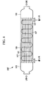
- the shell-and-tube-type heat exchanger 100 in the above form has a more complicated structure than a shell-and-tube-type heat exchanger 100' in which only one water chamber is provided as shown in Fig. 4 .
- the shell-and-tube-type heat exchanger 100 is disadvantageously high in cost and difficult to design.
- a method of preheating LNG in advance by another means may be used.
- an IFV (intermediate-fluid-type vaporizer) system has been proposed.
- the method called IFV system includes a preheating step of indirectly preheating LNG using a primary heating source such as seawater via a non-freezing heat medium such as propane, in the upstream side of the shell-and-tube-type heat exchanger.
- a primary heating source such as seawater
- a non-freezing heat medium such as propane
- the inexpensive shell-and-tube-type heat exchanger in which only one water chamber is provided can be thereby employed.
- the cost of the preheating step is high, handling and maintenance are troublesome because the non-freezing liquid such as propane is used, and an apparatus configuration also becomes complicated.
- the present invention has been made in view of such circumstances, and an object thereof is to provide a liquefied gas regasification plant which can regasify liquefied gas by a heat exchanger with a simple configuration by preheating the liquefied gas with a simple configuration, and a regasification method.
- a liquefied gas regasification plant, and a regasification method according to the present invention employ the following solutions.
- a liquefied gas regasification plant includes a preheating heat exchanger that preheats liquefied gas flowing through a preheated flow by a preheating fluid flowing through a preheating flow, and a first heat exchanger that regasifies the liquefied gas preheated in the preheating heat exchanger by seawater or fresh water, the gas regasified in the first heat exchanger being guided to the preheating flow, the liquefied gas regasification plant further including a second heat exchanger that regasifies the liquefied gas condensed through the preheating flow by seawater or fresh water.
- the gas regasified in the first heat exchanger is guided to the preheating flow so as to preheat the liquefied gas.
- the liquefied gas is preheated by using the own heat of the regasified gas, and the preheating is performed using the single fluid flowing through the continuous path.
- another heat medium such as propane in a preheating step.
- the preheating step can be achieved with a simple configuration.
- the liquefied gas preheated in the preheating heat exchanger is also guided to the first heat exchanger.
- the temperature of the liquefied gas flowing into the first heat exchanger is thereby increased.
- a heat medium such as seawater or fresh water freezes around a heat transfer tube, or heat exchange performance is deteriorated due to ice generated on a heat exchange surface.
- a shell-and-tube-type heat exchanger having a simple structure in which only one water chamber is provided can be employed.
- the liquefied gas condensed through the preheating flow of the preheating heat exchanger is also guided to the second heat exchanger.
- the temperature of the liquefied gas passing through the preheating flow is reduced by giving heat to the liquefied gas flowing through the preheated flow while flowing through the preheating flow.
- the gasification gas having a higher temperature than the liquefied gas flowing through the preheated flow is guided to the preheating flow, the liquefied gas cooled and condensed through the preheating flow can be prevented from being cooled to a temperature equal to that of the liquefied gas flowing into the preheating heat exchanger.
- the temperature of the liquefied gas flowing into the second heat exchanger can be thereby increased higher than the temperature of the liquefied gas.
- a heat medium such as seawater or fresh water freezes around a heat transfer tube, or heat exchange performance is deteriorated due to ice generated on a heat exchange surface in a similar manner to the first heat exchanger described above.
- a shell-and-tube-type heat exchanger for example, having a simple structure in which only one water chamber is provided can be employed.
- liquefied gas means not only a fluid in liquid phase, but also a fluid already gasified on an outlet side of the heat exchanger or a two-phase fluid having a predetermined wetness fraction.
- the shell-and-tube-type heat exchanger is preferably used as the first heat exchanger and/or the second heat exchanger.
- the present invention is not particularly limited thereto, and, for example, a heat exchanger with an ORV system described above may be employed.
- a non-freezing liquid may be added so as to further prevent the heat medium water from freezing.
- a cooling flow that precools or condenses boil-off gas may be provided in the preheating heat exchanger.
- a facility for reliquefying boil-off gas generated from a tank that stores liquefied gas or the like may be provided in some cases.
- the cooling flow that precools or condenses the boil-off gas is provided in the preheating heat exchanger, so that the liquefied gas can be more effectively preheated in conjunction with the cooling of the boil-off gas.
- a plate-type heat exchanger easily provided with a multi-flow configuration in which a plurality of independent flows is formed is preferably used as the preheating heat exchanger as described below.
- a plate-type heat exchanger may be used as the preheating heat exchanger.
- the preheating heat exchanger When the plate-type heat exchanger is used as the preheating heat exchanger, the preheating heat exchanger can be made compact.
- the plate-type heat exchanger may be a plate-fin-type or plate-coil-type heat exchanger.
- the plate-type heat exchanger is preferably made of stainless steel or aluminum alloy.
- a regasification method includes a preheating step of preheating liquefied gas flowing through a preheated flow by a preheating fluid flowing through a preheating flow by using a preheating heat exchanger, and a first regasification step of regasifying the liquefied gas preheated in the preheating step by seawater or fresh water by using a first heat exchanger, the gas regasified in the first heat exchanger being guided to the preheating flow, the method further including a second regasification step of regasifying the liquefied gas condensed through the preheating flow by a heat medium such as seawater or fresh water by using a second heat exchanger.
- the gas regasified in the first heat exchanger is guided to the preheating flow so as to preheat the liquefied gas.
- the liquefied gas is preheated by using the own heat of the regasified gas, and the preheating is performed using the single fluid flowing through the continuous path.
- another heat medium such as propane in the preheating step.
- the preheating step can be achieved with a simple configuration.
- the liquefied gas preheated in the preheating heat exchanger is guided.
- the temperature of the liquefied gas flowing into the first heat exchanger is thereby increased.
- seawater or fresh water freezes around a heat transfer tube. Accordingly, when a shell-and-tube-type heat exchanger is used as the first heat exchanger, a shell-and-tube-type heat exchanger having a simple structure in which only one water chamber is provided can be employed.
- the liquefied gas condensed through the preheating flow of the preheating heat exchanger is guided.
- the temperature of the liquefied gas passing through the preheating flow is reduced by giving heat to the liquefied gas flowing through the preheated flow while flowing through the preheating flow.
- the gasification gas having a higher temperature than the liquefied gas flowing through the preheated flow is guided to the preheating flow, the liquefied gas cooled and condensed through the preheating flow is not cooled to a temperature equal to that of the liquefied gas flowing into the preheating heat exchanger.
- the temperature of the liquefied gas flowing into the second heat exchanger can be thereby increased higher than the temperature of the liquefied gas.
- seawater or fresh water freezes around a heat transfer tube. Accordingly, when a shell-and-tube-type heat exchanger is used as the second heat exchanger, a shell-and-tube-type heat exchanger having a simple structure in which only one water chamber is provided can be employed.
- liquefied gas means not only a fluid in liquid phase, but also, in particular, a fluid gasified at an outlet of the heat exchanger or a two-phase fluid having a predetermined wetness fraction.
- the shell-and-tube-type heat exchanger is preferably used as the first heat exchanger and/or the second heat exchanger.
- the present invention is not particularly limited thereto, and, for example, a heat exchanger with an ORV system described above may be employed.
- a non-freezing liquid may be added.
- the liquefied gas is preheated by using the own heat of the regasified gas in the first heat exchanger, and the preheating is performed using the single fluid flowing through the continuous path.
- another heat medium such as propane in the preheating step.
- the preheating can be performed with a simple configuration.
- the heat exchanger with a simple configuration can be employed.
- the heat exchanger since the temperature of the liquefied gas flowing into the second heat exchanger can be increased higher than the temperature of the liquefied gas, there is less possibility that seawater or fresh water freezes around the heat transfer tube. Accordingly, the heat exchanger with a simple configuration can be employed.
- An LNG storage facility (liquefied gas storage facility) is provided in an offshore floating body such as an FSRU (floating storage and regasification unit) and an FPSO (floating production, storage and offloading), or a marine vessel such as an LNG carrier.
- Fig. 1 shows a regasification plant 1 that regasifies LNG (liquefied gas) guided from an LNG storage tank (liquefied gas storage tank) of the LNG storage facility so as to supply the LNG to a demand destination.
- the regasification plant 1 includes a preheating heat exchanger 3 that preheats the LNG, a first shell-and-tube-type heat exchanger (first heat exchanger) 5 that regasifies the liquefied gas preheated in the preheating heat exchanger 3 using seawater or fresh water, and a second shell-and-tube-type heat exchanger (second heat exchanger) 7 that regasifies the liquefied gas guided from the preheating heat exchanger 3 using seawater or fresh water.
- first heat exchanger first heat exchanger
- second heat exchanger 7 that regasifies the liquefied gas guided from the preheating heat exchanger 3 using seawater or fresh water.
- a preheated flow 3a to which the LNG fed from the LNG storage tank by a transfer pump is guided, and a preheating flow 3b to which gasification gas regasified in the first shell-and-tube-type heat exchanger 5 is guided are provided in the preheating heat exchanger 3.
- the preheating heat exchanger 3 is a plate-type heat exchanger.
- the plate-type heat exchanger may be a plate-fin-type or plate-coil-type heat exchanger.
- the plate-type heat exchanger is preferably made of stainless steel or aluminum alloy.
- the LNG passing through the preheated flow 3a is preheated, for example, from between -160°C and -155°C to between -100°C and -40°C.
- the preheated fluid is simply referred to as LNG (which means liquefied gas)
- the LNG means not only a fluid in liquid phase, but also a two-phase fluid having a predetermined wetness fraction.
- the gasification gas passing through the preheating flow 3b is heated by cooling the LNG passing through the preheated flow 3a.
- the gasification gas is cooled, for example, from about 10°C to between -100°C and -40°C.
- the temperature of the gasification gas flowing out of the preheating flow 3b can be set based on the design of the preheating heat exchanger 3.
- the temperature is preferably set equal to that of the LNG flowing out of the preheated flow 3a. Accordingly, the first shell-and-tube-type heat exchanger 5 and the second shell-and-tube-type heat exchanger 7 can be set to the same capacity.
- the first shell-and-tube-type heat exchanger 5 is a shell-and-tube-type heat exchanger having a simple structure in which only one water chamber is provided as shown in Fig. 4 . Seawater or fresh water is guided into the water chamber so as to form a counter flow with respect to an LNG flow.
- the preheated LNG is heated, for example, to about 10°C and regasified in the first shell-and-tube-type heat exchanger 5.
- the gasification gas regasified in the first shell-and-tube-type heat exchanger 5 is guided to the preheating flow 3b of the preheating heat exchanger 3 as described above.
- the second shell-and-tube-type heat exchanger 7 is a shell-and-tube-type heat exchanger having a simple structure in which only one water chamber is provided as shown in Fig. 4 in a similar manner to the first shell-and-tube-type heat exchanger 5. Seawater or fresh water is guided into the water chamber so as to form a counter flow with respect to an LNG flow.
- the LNG cooled and condensed in the preheating heat exchanger 3 is heated, for example, to about 10°C and regasified in the second shell-and-tube-type heat exchanger 7.
- the fluid cooled in the preheating heat exchanger 3 is simply referred to as LNG (which means liquefied gas)
- the LNG means not only a fluid in liquid phase, but also a fluid in gas phase, or a two-phase fluid having a predetermined wetness fraction.
- the gasification gas regasified in the second shell-and-tube-type heat exchanger 7 is guided to a CNG (compressed natural gas) manifold, and thereafter supplied to a demand destination.
- CNG compressed natural gas
- the aforementioned regasification plant 1 is used as described below so as to produce the regasified gas.
- the LNG fed from the LNG storage tank by the transfer pump is guided to the preheated flow 3a of the preheating heat exchanger 3, where the LNG is preheated, for example, to between -100°C and -40°C (a preheating step).
- the preheated LNG is guided to the first shell-and-tube-type heat exchanger 5, where the preheated LNG is heated, for example, to about 10°C and regasified using seawater or fresh water (a first regasification step).
- the regasified gasification gas is guided to the preheating flow 3b of the preheating heat exchanger 3, where the regasified gasification gas is cooled, for example, to between -100°C and -40°C by cooling the LNG flowing through the preheated flow 3a.
- the LNG flowing out of the preheating flow 3b is guided to the second shell-and-tube-type heat exchanger 7, where the LNG is heated, for example, to about 10°C and regasified using seawater or fresh water (a second regasification step).
- the regasified gasification gas is guided to the CNG manifold, and supplied to the demand destination.
- the gas regasified in the first shell-and-tube-type heat exchanger 5 is guided to the preheating flow 3b so as to preheat the LNG flowing through the preheated flow 3a.
- the LNG is preheated by using the own heat of the regasified gas, and the preheating is performed using the single fluid flowing through the continuous path.
- another heat medium such as propane in the preheating step.
- the preheating step can be achieved with a simple configuration.
- the LNG preheated in the preheating heat exchanger 3 is also guided to the first shell-and-tube-type heat exchanger 5.
- the temperature of the LNG flowing into the first shell-and-tube-type heat exchanger 5 is thereby increased.
- seawater or fresh water does not possibly freeze around a heat transfer tube. Accordingly, the shell-and-tube-type heat exchanger having a simple structure in which only one water chamber is provided can be employed.
- the LNG condensed through the preheating flow 3b of the preheating heat exchanger 3 is also guided to the second shell-and-tube-type heat exchanger 7. It is designed such that the temperature of the LNG passing through the preheating flow 3b is reduced by giving heat to the LNG flowing through the preheated flow 3a while flowing through the preheating flow 3b, but the LNG is not cooled to a temperature equal to that of the LNG flowing into the preheated flow 3a of the preheating heat exchanger 3.
- the temperature of the LNG flowing into the second shell-and-tube-type heat exchanger 7 can be thereby increased.
- seawater or fresh water does not possibly freeze around a heat transfer tube.
- the shell-and-tube-type heat exchanger having a simple structure in which only one water chamber is provided can be employed.
- the temperature of the LNG flowing out of the preheated flow 3a and flowing into the first shell-and-tube-type heat exchanger 5, and the temperature of the LNG flowing out of the preheating flow 3b and flowing into the second shell-and-tube-type heat exchanger 7 are set equal to each other.
- the first shell-and-tube-type heat exchanger 5 and the second shell-and-tube-type heat exchanger 7 can be set to the same capacity. Consequently, the shell-and-tube-type heat exchangers can be prepared at low cost.
- Fig. 2 shows a modification of the regasification plant according to the present embodiment.
- the preheating heat exchanger 3 is provided with a cooling flow 3c that precools or condenses boil-off gas (referred to as "BOG" below).
- BOG boil-off gas
- the BOG is inevitably generated from the LNG storage tank or the like by heat input.
- the BOG is cooled and reliquefied in some cases.
- a reliquefaction facility is installed adjacent to the regasification plant 1'.
- the cooling flow 3c that precools or condenses the BOG is provided in the preheating heat exchanger 3.
- the BOG precooled or condensed through the cooling flow 3c is guided to a condenser or a condensate tank.
- the LNG flowing through the preheated flow 3a can be more effectively preheated by the BOG in conjunction with the cooling of the BOG in the cooling flow 3c as described above.
- the plate-type heat exchanger is used as the preheating heat exchanger 3.
- the plate-type heat exchanger is easily provided with a multi-flow configuration in which a plurality of independent flows is formed, and is thus preferably used.
- the present invention is not limited thereto.
- another liquefied gas such as LPG (liquefied petroleum gas) and LEG (liquefied ethylene) may be also employed.
- the present invention is not limited thereto.
- the effects by preheating may be also obtained with respect to another heat exchanger.
- a heat exchanger with an ORV system may be employed.
Landscapes
- Engineering & Computer Science (AREA)
- Mechanical Engineering (AREA)
- General Engineering & Computer Science (AREA)
- Filling Or Discharging Of Gas Storage Vessels (AREA)
- Physics & Mathematics (AREA)
- Thermal Sciences (AREA)
- Chemical & Material Sciences (AREA)
- Combustion & Propulsion (AREA)
- Ocean & Marine Engineering (AREA)
Abstract
Description
- The present invention relates to a regasification plant which regasifies liquefied gas such as LNG, and a regasification method.
- Regasification plants are used to regasify LNG (liquefied natural gas) stored in a storage tank so as to supply the LNG to a demand destination. A regasification plant with an open-rack-type vaporizer (ORV) system is often used as the regasification plants (e.g., see PTL 1 below). In the ORV system, seawater, which is used as a heat source, is sprayed on the outer surfaces of a plurality of heat transfer tubes arranged in a panel-like manner in the atmosphere, and LNG inside the heat transfer tubes is thereby gasified. However, the ORV system disadvantageously requires much seawater, and needs to ensure a heat transfer area where seawater flows, thereby making it difficult to reduce the size of the regasification plant. Thus, it is difficult to install the ORV system in an offshore floating body such as an FSRU (floating storage and regasification unit) and an FPSO (floating production, storage and offloading), or a marine vessel such as an LNG carrier.
- Japanese Unexamined Patent Application, Publication No.
Hei9-14586 - Meanwhile, in some cases, a regasification plant with an STV (shell-and-tube-type vaporizer) system in which a shell-and-tube-
type heat exchanger 100 as shown inFig. 3 is used is installed in a floating body or a marine vessel as a regasification plant having a smaller size than that with the ORV system. - As a typical structure, the shell-and-tube-
type heat exchanger 100 includes anupstream header 103 into which LNG flows, a plurality ofheat transfer tubes 107 connected to theupstream header 103 in parallel with each other, and adownstream header 105 into which the LNG passing through theheat transfer tubes 107 flows as shown in the drawing. Each of theheat transfer tubes 107 penetrates through awater chamber 109 defined by a cylindrical body (shell). As a main feature of the heat exchanger, thewater chamber 109 is divided into an upstream-side water chamber 109a and a downstream-side water chamber 109b at a substantially longitudinal center portion. Seawater (S.W.) is guided into the upstream-side water chamber 109a from the most upstream side (the left side in the drawing) of an LNG flow. The seawater is discharged from the downstream side of the upstream-side water chamber 109a (see a dashed line in the drawing). That is, in the upstream-side water chamber 109a, the seawater forms a parallel flow with respect to the LNG flow. Meanwhile, seawater is guided into the downstream-side water chamber 109b from the most downstream side (the right side in the drawing) of the LNG flow. The seawater is discharged from the upstream side of the downstream-side water chamber 109b (see a dashed line in the drawing). That is, in the downstream-side water chamber 109b, the seawater forms a counter flow with respect to the LNG flow. As described above, the seawater having a high temperature is used in a parallel flow on the most upstream side where the temperature of the LNG is lowest, thereby avoiding freezing on the outer surfaces of the heat transfer tubes. The seawater is used in a counter flow on the most downstream side of the LNG flow, thereby ensuring an LNG removal temperature. - However, the shell-and-tube-
type heat exchanger 100 in the above form has a more complicated structure than a shell-and-tube-type heat exchanger 100' in which only one water chamber is provided as shown inFig. 4 . Thus, the shell-and-tube-type heat exchanger 100 is disadvantageously high in cost and difficult to design. - As a configuration for employing the shell-and-tube-type heat exchanger 100' in which only one water chamber is provided as shown in
Fig. 4 , a method of preheating LNG in advance by another means may be used. For example, an IFV (intermediate-fluid-type vaporizer) system has been proposed. The method called IFV system includes a preheating step of indirectly preheating LNG using a primary heating source such as seawater via a non-freezing heat medium such as propane, in the upstream side of the shell-and-tube-type heat exchanger. In the preheating step, the temperature of the LNG at an inlet of the shell-and-tube-type heat exchanger can be increased to a temperature at which the LNG hardly freezes. The inexpensive shell-and-tube-type heat exchanger in which only one water chamber is provided can be thereby employed. However, there are disadvantages that the cost of the preheating step is high, handling and maintenance are troublesome because the non-freezing liquid such as propane is used, and an apparatus configuration also becomes complicated. - The present invention has been made in view of such circumstances, and an object thereof is to provide a liquefied gas regasification plant which can regasify liquefied gas by a heat exchanger with a simple configuration by preheating the liquefied gas with a simple configuration, and a regasification method.
- To achieve the above object, a liquefied gas regasification plant, and a regasification method according to the present invention employ the following solutions.
- That is, a liquefied gas regasification plant according to a first aspect of the present invention includes a preheating heat exchanger that preheats liquefied gas flowing through a preheated flow by a preheating fluid flowing through a preheating flow, and a first heat exchanger that regasifies the liquefied gas preheated in the preheating heat exchanger by seawater or fresh water, the gas regasified in the first heat exchanger being guided to the preheating flow, the liquefied gas regasification plant further including a second heat exchanger that regasifies the liquefied gas condensed through the preheating flow by seawater or fresh water.
- In the preheating heat exchanger, the gas regasified in the first heat exchanger is guided to the preheating flow so as to preheat the liquefied gas. As described above, the liquefied gas is preheated by using the own heat of the regasified gas, and the preheating is performed using the single fluid flowing through the continuous path. Thus, it is not necessary to use another heat medium such as propane in a preheating step. The preheating step can be achieved with a simple configuration.
- The liquefied gas preheated in the preheating heat exchanger is also guided to the first heat exchanger. The temperature of the liquefied gas flowing into the first heat exchanger is thereby increased. Thus, there is less possibility that a heat medium such as seawater or fresh water freezes around a heat transfer tube, or heat exchange performance is deteriorated due to ice generated on a heat exchange surface. Accordingly, when a shell-and-tube-type heat exchanger is used as the first heat exchanger, a shell-and-tube-type heat exchanger having a simple structure in which only one water chamber is provided can be employed.
- The liquefied gas condensed through the preheating flow of the preheating heat exchanger is also guided to the second heat exchanger. The temperature of the liquefied gas passing through the preheating flow is reduced by giving heat to the liquefied gas flowing through the preheated flow while flowing through the preheating flow. However, since the gasification gas having a higher temperature than the liquefied gas flowing through the preheated flow is guided to the preheating flow, the liquefied gas cooled and condensed through the preheating flow can be prevented from being cooled to a temperature equal to that of the liquefied gas flowing into the preheating heat exchanger. The temperature of the liquefied gas flowing into the second heat exchanger can be thereby increased higher than the temperature of the liquefied gas. Thus, there is less possibility that a heat medium such as seawater or fresh water freezes around a heat transfer tube, or heat exchange performance is deteriorated due to ice generated on a heat exchange surface in a similar manner to the first heat exchanger described above. Accordingly, when a shell-and-tube-type heat exchanger is used as the first heat exchanger, a shell-and-tube-type heat exchanger, for example, having a simple structure in which only one water chamber is provided can be employed.
- While the fluid flowing out of the preheated flow and the preheating flow of the preheating heat exchanger is referred to as "liquefied gas", the liquefied gas means not only a fluid in liquid phase, but also a fluid already gasified on an outlet side of the heat exchanger or a two-phase fluid having a predetermined wetness fraction.
- Also, the shell-and-tube-type heat exchanger is preferably used as the first heat exchanger and/or the second heat exchanger. However, the present invention is not particularly limited thereto, and, for example, a heat exchanger with an ORV system described above may be employed.
- Also, when the liquefied gas is heated using a secondary closed loop of fresh water or the like as the heating medium in the first heat exchanger and the second heat exchanger, a non-freezing liquid may be added so as to further prevent the heat medium water from freezing.
- Moreover, in the liquefied gas regasification plant according to the first aspect, a cooling flow that precools or condenses boil-off gas may be provided in the preheating heat exchanger.
- A facility for reliquefying boil-off gas generated from a tank that stores liquefied gas or the like may be provided in some cases. In this case, the cooling flow that precools or condenses the boil-off gas is provided in the preheating heat exchanger, so that the liquefied gas can be more effectively preheated in conjunction with the cooling of the boil-off gas.
- Particularly, a plate-type heat exchanger easily provided with a multi-flow configuration in which a plurality of independent flows is formed is preferably used as the preheating heat exchanger as described below.
- Moreover, in the liquefied gas regasification plant according to the first aspect, a plate-type heat exchanger may be used as the preheating heat exchanger.
- When the plate-type heat exchanger is used as the preheating heat exchanger, the preheating heat exchanger can be made compact.
- To be more specific, the plate-type heat exchanger may be a plate-fin-type or plate-coil-type heat exchanger. The plate-type heat exchanger is preferably made of stainless steel or aluminum alloy.
- Also, a regasification method according to a second aspect of the present invention includes a preheating step of preheating liquefied gas flowing through a preheated flow by a preheating fluid flowing through a preheating flow by using a preheating heat exchanger, and a first regasification step of regasifying the liquefied gas preheated in the preheating step by seawater or fresh water by using a first heat exchanger, the gas regasified in the first heat exchanger being guided to the preheating flow, the method further including a second regasification step of regasifying the liquefied gas condensed through the preheating flow by a heat medium such as seawater or fresh water by using a second heat exchanger.
- In the preheating step by the preheating heat exchanger, the gas regasified in the first heat exchanger is guided to the preheating flow so as to preheat the liquefied gas. As described above, the liquefied gas is preheated by using the own heat of the regasified gas, and the preheating is performed using the single fluid flowing through the continuous path. Thus, it is not necessary to use another heat medium such as propane in the preheating step. The preheating step can be achieved with a simple configuration.
- Also, in the first regasification step by the first heat exchanger, the liquefied gas preheated in the preheating heat exchanger is guided. The temperature of the liquefied gas flowing into the first heat exchanger is thereby increased. Thus, there is less possibility that seawater or fresh water freezes around a heat transfer tube. Accordingly, when a shell-and-tube-type heat exchanger is used as the first heat exchanger, a shell-and-tube-type heat exchanger having a simple structure in which only one water chamber is provided can be employed.
- Also, in the second regasification step by the second heat exchanger, the liquefied gas condensed through the preheating flow of the preheating heat exchanger is guided. The temperature of the liquefied gas passing through the preheating flow is reduced by giving heat to the liquefied gas flowing through the preheated flow while flowing through the preheating flow. However, since the gasification gas having a higher temperature than the liquefied gas flowing through the preheated flow is guided to the preheating flow, the liquefied gas cooled and condensed through the preheating flow is not cooled to a temperature equal to that of the liquefied gas flowing into the preheating heat exchanger. The temperature of the liquefied gas flowing into the second heat exchanger can be thereby increased higher than the temperature of the liquefied gas. Thus, there is less possibility that seawater or fresh water freezes around a heat transfer tube. Accordingly, when a shell-and-tube-type heat exchanger is used as the second heat exchanger, a shell-and-tube-type heat exchanger having a simple structure in which only one water chamber is provided can be employed.
- While the fluid flowing out of the preheated flow and the preheating flow of the preheating heat exchanger is referred to as "liquefied gas", the liquefied gas means not only a fluid in liquid phase, but also, in particular, a fluid gasified at an outlet of the heat exchanger or a two-phase fluid having a predetermined wetness fraction.
- Also, the shell-and-tube-type heat exchanger is preferably used as the first heat exchanger and/or the second heat exchanger. However, the present invention is not particularly limited thereto, and, for example, a heat exchanger with an ORV system described above may be employed.
- Also, when a secondary closed loop of fresh water or the like is used as the heating medium in the first heat exchanger and the second heat exchanger, a non-freezing liquid may be added.
- In the preheating heat exchanger, the liquefied gas is preheated by using the own heat of the regasified gas in the first heat exchanger, and the preheating is performed using the single fluid flowing through the continuous path. Thus, it is not necessary to use another heat medium such as propane in the preheating step. The preheating can be performed with a simple configuration.
- Also, since the liquefied gas is preheated, there is less possibility that freezing occurs around the heat transfer tube of the first heat exchanger. Accordingly, the heat exchanger with a simple configuration can be employed.
- Also, since the temperature of the liquefied gas flowing into the second heat exchanger can be increased higher than the temperature of the liquefied gas, there is less possibility that seawater or fresh water freezes around the heat transfer tube. Accordingly, the heat exchanger with a simple configuration can be employed.
-
- {
Fig. 1 }
Fig. 1 is a view illustrating a liquefied gas regasification plant according to a first embodiment of the present invention. - {
Fig. 2 }
Fig. 2 is a view illustrating a modification ofFig. 1 . - {
Fig. 3 }
Fig. 3 is a longitudinal sectional view illustrating a shell-and-tube-type heat exchanger in which two water chambers are provided. - {
Fig. 4 }
Fig. 4 is a longitudinal sectional view illustrating a shell-and-tube-type heat exchanger in which only one water chamber is provided. - In the following, an embodiment according to the present invention will be described by reference to the drawings.
- In the following, a first embodiment of the present invention will be described.
- An LNG storage facility (liquefied gas storage facility) is provided in an offshore floating body such as an FSRU (floating storage and regasification unit) and an FPSO (floating production, storage and offloading), or a marine vessel such as an LNG carrier.
Fig. 1 shows a regasification plant 1 that regasifies LNG (liquefied gas) guided from an LNG storage tank (liquefied gas storage tank) of the LNG storage facility so as to supply the LNG to a demand destination. - As shown in
Fig. 1 , the regasification plant 1 includes a preheatingheat exchanger 3 that preheats the LNG, a first shell-and-tube-type heat exchanger (first heat exchanger) 5 that regasifies the liquefied gas preheated in the preheatingheat exchanger 3 using seawater or fresh water, and a second shell-and-tube-type heat exchanger (second heat exchanger) 7 that regasifies the liquefied gas guided from the preheatingheat exchanger 3 using seawater or fresh water. - A
preheated flow 3a to which the LNG fed from the LNG storage tank by a transfer pump is guided, and a preheatingflow 3b to which gasification gas regasified in the first shell-and-tube-type heat exchanger 5 is guided are provided in the preheatingheat exchanger 3. - The preheating
heat exchanger 3 is a plate-type heat exchanger. To be more specific, the plate-type heat exchanger may be a plate-fin-type or plate-coil-type heat exchanger. The plate-type heat exchanger is preferably made of stainless steel or aluminum alloy. - In the preheating
heat exchanger 3, the LNG passing through thepreheated flow 3a is preheated, for example, from between -160°C and -155°C to between -100°C and -40°C. While the preheated fluid is simply referred to as LNG (which means liquefied gas), the LNG means not only a fluid in liquid phase, but also a two-phase fluid having a predetermined wetness fraction. - The gasification gas passing through the preheating
flow 3b is heated by cooling the LNG passing through thepreheated flow 3a. The gasification gas is cooled, for example, from about 10°C to between -100°C and -40°C. The temperature of the gasification gas flowing out of the preheatingflow 3b can be set based on the design of the preheatingheat exchanger 3. The temperature is preferably set equal to that of the LNG flowing out of thepreheated flow 3a. Accordingly, the first shell-and-tube-type heat exchanger 5 and the second shell-and-tube-type heat exchanger 7 can be set to the same capacity. - The first shell-and-tube-
type heat exchanger 5 is a shell-and-tube-type heat exchanger having a simple structure in which only one water chamber is provided as shown inFig. 4 . Seawater or fresh water is guided into the water chamber so as to form a counter flow with respect to an LNG flow. The preheated LNG is heated, for example, to about 10°C and regasified in the first shell-and-tube-type heat exchanger 5. - The gasification gas regasified in the first shell-and-tube-
type heat exchanger 5 is guided to the preheatingflow 3b of the preheatingheat exchanger 3 as described above. - The second shell-and-tube-type heat exchanger 7 is a shell-and-tube-type heat exchanger having a simple structure in which only one water chamber is provided as shown in
Fig. 4 in a similar manner to the first shell-and-tube-type heat exchanger 5. Seawater or fresh water is guided into the water chamber so as to form a counter flow with respect to an LNG flow. The LNG cooled and condensed in the preheatingheat exchanger 3 is heated, for example, to about 10°C and regasified in the second shell-and-tube-type heat exchanger 7. While the fluid cooled in the preheatingheat exchanger 3 is simply referred to as LNG (which means liquefied gas), the LNG means not only a fluid in liquid phase, but also a fluid in gas phase, or a two-phase fluid having a predetermined wetness fraction. - The gasification gas regasified in the second shell-and-tube-type heat exchanger 7 is guided to a CNG (compressed natural gas) manifold, and thereafter supplied to a demand destination.
- The aforementioned regasification plant 1 is used as described below so as to produce the regasified gas.
- The LNG fed from the LNG storage tank by the transfer pump is guided to the
preheated flow 3a of the preheatingheat exchanger 3, where the LNG is preheated, for example, to between -100°C and -40°C (a preheating step). - The preheated LNG is guided to the first shell-and-tube-
type heat exchanger 5, where the preheated LNG is heated, for example, to about 10°C and regasified using seawater or fresh water (a first regasification step). - The regasified gasification gas is guided to the preheating
flow 3b of the preheatingheat exchanger 3, where the regasified gasification gas is cooled, for example, to between -100°C and -40°C by cooling the LNG flowing through thepreheated flow 3a. - The LNG flowing out of the preheating
flow 3b is guided to the second shell-and-tube-type heat exchanger 7, where the LNG is heated, for example, to about 10°C and regasified using seawater or fresh water (a second regasification step). - The regasified gasification gas is guided to the CNG manifold, and supplied to the demand destination.
- Following effects are obtained by the regasification plant 1 in the present embodiment.
- In the preheating
heat exchanger 3, the gas regasified in the first shell-and-tube-type heat exchanger 5 is guided to the preheatingflow 3b so as to preheat the LNG flowing through thepreheated flow 3a. As described above, the LNG is preheated by using the own heat of the regasified gas, and the preheating is performed using the single fluid flowing through the continuous path. Thus, it is not necessary to use another heat medium such as propane in the preheating step. The preheating step can be achieved with a simple configuration. - The LNG preheated in the preheating
heat exchanger 3 is also guided to the first shell-and-tube-type heat exchanger 5. The temperature of the LNG flowing into the first shell-and-tube-type heat exchanger 5 is thereby increased. Thus, seawater or fresh water does not possibly freeze around a heat transfer tube. Accordingly, the shell-and-tube-type heat exchanger having a simple structure in which only one water chamber is provided can be employed. - The LNG condensed through the preheating
flow 3b of the preheatingheat exchanger 3 is also guided to the second shell-and-tube-type heat exchanger 7. It is designed such that the temperature of the LNG passing through the preheatingflow 3b is reduced by giving heat to the LNG flowing through thepreheated flow 3a while flowing through the preheatingflow 3b, but the LNG is not cooled to a temperature equal to that of the LNG flowing into thepreheated flow 3a of the preheatingheat exchanger 3. The temperature of the LNG flowing into the second shell-and-tube-type heat exchanger 7 can be thereby increased. Thus, seawater or fresh water does not possibly freeze around a heat transfer tube. Accordingly, the shell-and-tube-type heat exchanger having a simple structure in which only one water chamber is provided can be employed. Particularly, in the present embodiment, the temperature of the LNG flowing out of thepreheated flow 3a and flowing into the first shell-and-tube-type heat exchanger 5, and the temperature of the LNG flowing out of the preheatingflow 3b and flowing into the second shell-and-tube-type heat exchanger 7 are set equal to each other. Thus, the first shell-and-tube-type heat exchanger 5 and the second shell-and-tube-type heat exchanger 7 can be set to the same capacity. Consequently, the shell-and-tube-type heat exchangers can be prepared at low cost. -
Fig. 2 shows a modification of the regasification plant according to the present embodiment. - In a regasification plant 1', the preheating
heat exchanger 3 is provided with acooling flow 3c that precools or condenses boil-off gas (referred to as "BOG" below). The other components in the configuration are similar to those inFig. 1 , and thus assigned the same reference numerals to omit the description thereof. - The BOG is inevitably generated from the LNG storage tank or the like by heat input. The BOG is cooled and reliquefied in some cases. When the BOG is reliquefied, a reliquefaction facility is installed adjacent to the regasification plant 1'. In this case, the
cooling flow 3c that precools or condenses the BOG is provided in the preheatingheat exchanger 3. The BOG precooled or condensed through thecooling flow 3c is guided to a condenser or a condensate tank. - The LNG flowing through the
preheated flow 3a can be more effectively preheated by the BOG in conjunction with the cooling of the BOG in thecooling flow 3c as described above. - Particularly, in the present embodiment, the plate-type heat exchanger is used as the preheating
heat exchanger 3. The plate-type heat exchanger is easily provided with a multi-flow configuration in which a plurality of independent flows is formed, and is thus preferably used. - Although the LNG is described as an example of the liquefied gas in the aforementioned embodiment, the present invention is not limited thereto. For example, another liquefied gas such as LPG (liquefied petroleum gas) and LEG (liquefied ethylene) may be also employed.
- Also, although the aforementioned embodiment is described using the first shell-and-tube-type heat exchanger and the second shell-and-tube-type heat exchanger, the present invention is not limited thereto. The effects by preheating may be also obtained with respect to another heat exchanger. For example, a heat exchanger with an ORV system may be employed.
-
- 1, 1' Regasification plant
- 3 Preheating heat exchanger
- 3a Preheated flow
- 3b Preheating flow
- 3c Cooling flow
- 5 First shell-and-tube-type heat exchanger (first heat exchanger)
- 7 Second shell-and-tube-type heat exchanger (second heat exchanger)
Claims (5)
- A liquefied gas regasification plant comprising
a preheating heat exchanger that preheats liquefied gas flowing through a preheated flow by a preheating fluid flowing through a preheating flow, and
a first heat exchanger that regasifies the liquefied gas preheated in the preheating heat exchanger by seawater or fresh water,
the gas regasified in the first heat exchanger being guided to the preheating flow,
the liquefied gas regasification plant further comprising a second heat exchanger that regasifies the liquefied gas condensed through the preheating flow by seawater or fresh water. - The liquefied gas regasification plant according to claim 1, wherein a shell-and-tube-type heat exchanger is used as the first heat exchanger and/or the second heat exchanger.
- The liquefied gas regasification plant according to claim 1 or 2, wherein a cooling flow that precools or condenses boil-off gas is provided in the preheating heat exchanger.
- The liquefied gas regasification plant according to any one of claims 1 to 3, wherein a plate-type heat exchanger is used as the preheating heat exchanger.
- A regasification method comprising
a preheating step of preheating liquefied gas flowing through a preheated flow by a preheating fluid flowing through a preheating flow by using a preheating heat exchanger, and
a first regasification step of regasifying the liquefied gas preheated in the preheating step by seawater or fresh water by using a first heat exchanger,
the gas regasified in the first heat exchanger being guided to the preheating flow,
the method further comprising a second regasification step of regasifying the liquefied gas condensed through the preheating flow by seawater or fresh water by using a second heat exchanger.
Applications Claiming Priority (2)
| Application Number | Priority Date | Filing Date | Title |
|---|---|---|---|
| JP2011043192A JP5999874B2 (en) | 2011-02-28 | 2011-02-28 | Liquefied gas regasification apparatus and regasification gas production method |
| PCT/JP2012/052518 WO2012117806A1 (en) | 2011-02-28 | 2012-02-03 | Liquefied gas regasificaion device and method for manufacturing regasified gas |
Publications (3)
| Publication Number | Publication Date |
|---|---|
| EP2682666A1 true EP2682666A1 (en) | 2014-01-08 |
| EP2682666A4 EP2682666A4 (en) | 2018-01-17 |
| EP2682666B1 EP2682666B1 (en) | 2020-03-25 |
Family
ID=46757745
Family Applications (1)
| Application Number | Title | Priority Date | Filing Date |
|---|---|---|---|
| EP12752343.9A Active EP2682666B1 (en) | 2011-02-28 | 2012-02-03 | Liquefied gas regasificaion device and method for manufacturing regasified gas |
Country Status (5)
| Country | Link |
|---|---|
| EP (1) | EP2682666B1 (en) |
| JP (1) | JP5999874B2 (en) |
| KR (2) | KR101840529B1 (en) |
| CN (1) | CN103403437B (en) |
| WO (1) | WO2012117806A1 (en) |
Cited By (2)
| Publication number | Priority date | Publication date | Assignee | Title |
|---|---|---|---|---|
| WO2017095230A1 (en) | 2015-12-01 | 2017-06-08 | Wärtsilä Oil & Gas Systems As | A plant and method for regasification of lng |
| US10775080B2 (en) | 2015-10-05 | 2020-09-15 | Crowley Maritime Corporation | LNG gasification systems and methods |
Families Citing this family (4)
| Publication number | Priority date | Publication date | Assignee | Title |
|---|---|---|---|---|
| CN104315339B (en) * | 2014-10-27 | 2016-02-24 | 中国海洋石油总公司 | Be applied to LNG cascade regas system and the regasification process of offshore floating type LNG regasification plant |
| JP6454628B2 (en) * | 2015-10-21 | 2019-01-16 | 株式会社神戸製鋼所 | Intermediate medium gas vaporizer |
| JP6666703B2 (en) * | 2015-12-08 | 2020-03-18 | 株式会社Ihiプラント | Heat exchanger |
| JP7042383B1 (en) * | 2021-10-29 | 2022-03-25 | 岩井機械工業株式会社 | Multi-tube heat exchanger and heat exchange system |
Family Cites Families (8)
| Publication number | Priority date | Publication date | Assignee | Title |
|---|---|---|---|---|
| FR2582785B1 (en) * | 1985-04-26 | 1989-04-28 | Agliani Philippe | SELF-CONTAINED SYSTEM FOR COOLING GAS FLUIDS SUCH AS AIR |
| US5373701A (en) * | 1993-07-07 | 1994-12-20 | The Boc Group, Inc. | Cryogenic station |
| JP3354750B2 (en) * | 1995-06-23 | 2002-12-09 | 中部電力株式会社 | LNG vaporizer for fuel of natural gas-fired gas turbine combined cycle power plant |
| JP3591927B2 (en) * | 1995-08-25 | 2004-11-24 | 株式会社神戸製鋼所 | Cryogenic liquid with multiple components and boil-off gas treatment device |
| JP3821506B2 (en) * | 1995-12-28 | 2006-09-13 | 大陽日酸株式会社 | Evaporative gas reliquefaction equipment for liquefied natural gas storage tanks |
| FR2879720B1 (en) * | 2004-12-17 | 2007-04-06 | Snecma Moteurs Sa | COMPRESSION-EVAPORATION SYSTEM FOR LIQUEFIED GAS |
| JP2009192004A (en) * | 2008-02-15 | 2009-08-27 | Ihi Corp | Liquefied gas vaporizing equipment |
| DE102008013084A1 (en) * | 2008-03-07 | 2009-09-24 | Messer Group Gmbh | Apparatus and method for removing gas from a container |
-
2011
- 2011-02-28 JP JP2011043192A patent/JP5999874B2/en active Active
-
2012
- 2012-02-03 KR KR1020157032354A patent/KR101840529B1/en active Active
- 2012-02-03 WO PCT/JP2012/052518 patent/WO2012117806A1/en not_active Ceased
- 2012-02-03 EP EP12752343.9A patent/EP2682666B1/en active Active
- 2012-02-03 CN CN201280010015.5A patent/CN103403437B/en active Active
- 2012-02-03 KR KR1020137022027A patent/KR20130117858A/en not_active Ceased
Non-Patent Citations (1)
| Title |
|---|
| See references of WO2012117806A1 * |
Cited By (2)
| Publication number | Priority date | Publication date | Assignee | Title |
|---|---|---|---|---|
| US10775080B2 (en) | 2015-10-05 | 2020-09-15 | Crowley Maritime Corporation | LNG gasification systems and methods |
| WO2017095230A1 (en) | 2015-12-01 | 2017-06-08 | Wärtsilä Oil & Gas Systems As | A plant and method for regasification of lng |
Also Published As
| Publication number | Publication date |
|---|---|
| JP2012180877A (en) | 2012-09-20 |
| CN103403437A (en) | 2013-11-20 |
| KR20130117858A (en) | 2013-10-28 |
| KR101840529B1 (en) | 2018-03-20 |
| JP5999874B2 (en) | 2016-09-28 |
| CN103403437B (en) | 2016-06-22 |
| EP2682666B1 (en) | 2020-03-25 |
| WO2012117806A1 (en) | 2012-09-07 |
| EP2682666A4 (en) | 2018-01-17 |
| KR20150133294A (en) | 2015-11-27 |
Similar Documents
| Publication | Publication Date | Title |
|---|---|---|
| US6945049B2 (en) | Regasification system and method | |
| US9695984B2 (en) | Plant for regasification of LNG | |
| EP1064506B1 (en) | Regasification of lng aboard a transport vessel | |
| US7155917B2 (en) | Apparatus and methods for converting a cryogenic fluid into gas | |
| US20120060516A1 (en) | Fuel gas supply system and method of an lng carrier | |
| EP2682666B1 (en) | Liquefied gas regasificaion device and method for manufacturing regasified gas | |
| KR101726668B1 (en) | System And Method For Treatment Of Boil Off Gas | |
| KR20120064221A (en) | Vessel | |
| JP3821506B2 (en) | Evaporative gas reliquefaction equipment for liquefied natural gas storage tanks | |
| WO2004031644A1 (en) | Regasification system and method | |
| JP7775302B2 (en) | Gas supply systems for high-pressure and low-pressure gas consuming equipment | |
| KR200493619Y1 (en) | LNG Regasification Apparatus and Ship including the same | |
| KR101010329B1 (en) | Evaporative gas cooling system of the LAN storage tank in the LAN carrier | |
| KR102951208B1 (en) | Gas Treatment System Of Ship | |
| JP2024147506A (en) | Gas supply systems for devices consuming high and low pressure gas |
Legal Events
| Date | Code | Title | Description |
|---|---|---|---|
| PUAI | Public reference made under article 153(3) epc to a published international application that has entered the european phase |
Free format text: ORIGINAL CODE: 0009012 |
|
| 17P | Request for examination filed |
Effective date: 20130823 |
|
| AK | Designated contracting states |
Kind code of ref document: A1 Designated state(s): AL AT BE BG CH CY CZ DE DK EE ES FI FR GB GR HR HU IE IS IT LI LT LU LV MC MK MT NL NO PL PT RO RS SE SI SK SM TR |
|
| DAX | Request for extension of the european patent (deleted) | ||
| RA4 | Supplementary search report drawn up and despatched (corrected) |
Effective date: 20171219 |
|
| RIC1 | Information provided on ipc code assigned before grant |
Ipc: F17C 9/04 20060101AFI20171213BHEP |
|
| RAP1 | Party data changed (applicant data changed or rights of an application transferred) |
Owner name: MITSUBISHI SHIPBUILDING CO., LTD. |
|
| GRAP | Despatch of communication of intention to grant a patent |
Free format text: ORIGINAL CODE: EPIDOSNIGR1 |
|
| STAA | Information on the status of an ep patent application or granted ep patent |
Free format text: STATUS: GRANT OF PATENT IS INTENDED |
|
| RIN1 | Information on inventor provided before grant (corrected) |
Inventor name: OKA, MASARU |
|
| INTG | Intention to grant announced |
Effective date: 20191114 |
|
| GRAS | Grant fee paid |
Free format text: ORIGINAL CODE: EPIDOSNIGR3 |
|
| GRAA | (expected) grant |
Free format text: ORIGINAL CODE: 0009210 |
|
| STAA | Information on the status of an ep patent application or granted ep patent |
Free format text: STATUS: THE PATENT HAS BEEN GRANTED |
|
| AK | Designated contracting states |
Kind code of ref document: B1 Designated state(s): AL AT BE BG CH CY CZ DE DK EE ES FI FR GB GR HR HU IE IS IT LI LT LU LV MC MK MT NL NO PL PT RO RS SE SI SK SM TR |
|
| REG | Reference to a national code |
Ref country code: GB Ref legal event code: FG4D |
|
| REG | Reference to a national code |
Ref country code: DE Ref legal event code: R096 Ref document number: 602012068739 Country of ref document: DE |
|
| REG | Reference to a national code |
Ref country code: AT Ref legal event code: REF Ref document number: 1248956 Country of ref document: AT Kind code of ref document: T Effective date: 20200415 Ref country code: IE Ref legal event code: FG4D |
|
| REG | Reference to a national code |
Ref country code: NO Ref legal event code: T2 Effective date: 20200325 |
|
| PG25 | Lapsed in a contracting state [announced via postgrant information from national office to epo] |
Ref country code: RS Free format text: LAPSE BECAUSE OF FAILURE TO SUBMIT A TRANSLATION OF THE DESCRIPTION OR TO PAY THE FEE WITHIN THE PRESCRIBED TIME-LIMIT Effective date: 20200325 Ref country code: FI Free format text: LAPSE BECAUSE OF FAILURE TO SUBMIT A TRANSLATION OF THE DESCRIPTION OR TO PAY THE FEE WITHIN THE PRESCRIBED TIME-LIMIT Effective date: 20200325 |
|
| PG25 | Lapsed in a contracting state [announced via postgrant information from national office to epo] |
Ref country code: HR Free format text: LAPSE BECAUSE OF FAILURE TO SUBMIT A TRANSLATION OF THE DESCRIPTION OR TO PAY THE FEE WITHIN THE PRESCRIBED TIME-LIMIT Effective date: 20200325 Ref country code: GR Free format text: LAPSE BECAUSE OF FAILURE TO SUBMIT A TRANSLATION OF THE DESCRIPTION OR TO PAY THE FEE WITHIN THE PRESCRIBED TIME-LIMIT Effective date: 20200626 Ref country code: BG Free format text: LAPSE BECAUSE OF FAILURE TO SUBMIT A TRANSLATION OF THE DESCRIPTION OR TO PAY THE FEE WITHIN THE PRESCRIBED TIME-LIMIT Effective date: 20200625 Ref country code: LV Free format text: LAPSE BECAUSE OF FAILURE TO SUBMIT A TRANSLATION OF THE DESCRIPTION OR TO PAY THE FEE WITHIN THE PRESCRIBED TIME-LIMIT Effective date: 20200325 Ref country code: SE Free format text: LAPSE BECAUSE OF FAILURE TO SUBMIT A TRANSLATION OF THE DESCRIPTION OR TO PAY THE FEE WITHIN THE PRESCRIBED TIME-LIMIT Effective date: 20200325 |
|
| REG | Reference to a national code |
Ref country code: NL Ref legal event code: MP Effective date: 20200325 |
|
| REG | Reference to a national code |
Ref country code: LT Ref legal event code: MG4D |
|
| PG25 | Lapsed in a contracting state [announced via postgrant information from national office to epo] |
Ref country code: NL Free format text: LAPSE BECAUSE OF FAILURE TO SUBMIT A TRANSLATION OF THE DESCRIPTION OR TO PAY THE FEE WITHIN THE PRESCRIBED TIME-LIMIT Effective date: 20200325 |
|
| PG25 | Lapsed in a contracting state [announced via postgrant information from national office to epo] |
Ref country code: RO Free format text: LAPSE BECAUSE OF FAILURE TO SUBMIT A TRANSLATION OF THE DESCRIPTION OR TO PAY THE FEE WITHIN THE PRESCRIBED TIME-LIMIT Effective date: 20200325 Ref country code: CZ Free format text: LAPSE BECAUSE OF FAILURE TO SUBMIT A TRANSLATION OF THE DESCRIPTION OR TO PAY THE FEE WITHIN THE PRESCRIBED TIME-LIMIT Effective date: 20200325 Ref country code: LT Free format text: LAPSE BECAUSE OF FAILURE TO SUBMIT A TRANSLATION OF THE DESCRIPTION OR TO PAY THE FEE WITHIN THE PRESCRIBED TIME-LIMIT Effective date: 20200325 Ref country code: EE Free format text: LAPSE BECAUSE OF FAILURE TO SUBMIT A TRANSLATION OF THE DESCRIPTION OR TO PAY THE FEE WITHIN THE PRESCRIBED TIME-LIMIT Effective date: 20200325 Ref country code: PT Free format text: LAPSE BECAUSE OF FAILURE TO SUBMIT A TRANSLATION OF THE DESCRIPTION OR TO PAY THE FEE WITHIN THE PRESCRIBED TIME-LIMIT Effective date: 20200818 Ref country code: IS Free format text: LAPSE BECAUSE OF FAILURE TO SUBMIT A TRANSLATION OF THE DESCRIPTION OR TO PAY THE FEE WITHIN THE PRESCRIBED TIME-LIMIT Effective date: 20200725 Ref country code: SM Free format text: LAPSE BECAUSE OF FAILURE TO SUBMIT A TRANSLATION OF THE DESCRIPTION OR TO PAY THE FEE WITHIN THE PRESCRIBED TIME-LIMIT Effective date: 20200325 Ref country code: SK Free format text: LAPSE BECAUSE OF FAILURE TO SUBMIT A TRANSLATION OF THE DESCRIPTION OR TO PAY THE FEE WITHIN THE PRESCRIBED TIME-LIMIT Effective date: 20200325 |
|
| REG | Reference to a national code |
Ref country code: AT Ref legal event code: MK05 Ref document number: 1248956 Country of ref document: AT Kind code of ref document: T Effective date: 20200325 |
|
| REG | Reference to a national code |
Ref country code: DE Ref legal event code: R097 Ref document number: 602012068739 Country of ref document: DE |
|
| PG25 | Lapsed in a contracting state [announced via postgrant information from national office to epo] |
Ref country code: IT Free format text: LAPSE BECAUSE OF FAILURE TO SUBMIT A TRANSLATION OF THE DESCRIPTION OR TO PAY THE FEE WITHIN THE PRESCRIBED TIME-LIMIT Effective date: 20200325 Ref country code: DK Free format text: LAPSE BECAUSE OF FAILURE TO SUBMIT A TRANSLATION OF THE DESCRIPTION OR TO PAY THE FEE WITHIN THE PRESCRIBED TIME-LIMIT Effective date: 20200325 Ref country code: AT Free format text: LAPSE BECAUSE OF FAILURE TO SUBMIT A TRANSLATION OF THE DESCRIPTION OR TO PAY THE FEE WITHIN THE PRESCRIBED TIME-LIMIT Effective date: 20200325 Ref country code: ES Free format text: LAPSE BECAUSE OF FAILURE TO SUBMIT A TRANSLATION OF THE DESCRIPTION OR TO PAY THE FEE WITHIN THE PRESCRIBED TIME-LIMIT Effective date: 20200325 |
|
| PLBE | No opposition filed within time limit |
Free format text: ORIGINAL CODE: 0009261 |
|
| STAA | Information on the status of an ep patent application or granted ep patent |
Free format text: STATUS: NO OPPOSITION FILED WITHIN TIME LIMIT |
|
| PG25 | Lapsed in a contracting state [announced via postgrant information from national office to epo] |
Ref country code: PL Free format text: LAPSE BECAUSE OF FAILURE TO SUBMIT A TRANSLATION OF THE DESCRIPTION OR TO PAY THE FEE WITHIN THE PRESCRIBED TIME-LIMIT Effective date: 20200325 |
|
| 26N | No opposition filed |
Effective date: 20210112 |
|
| PG25 | Lapsed in a contracting state [announced via postgrant information from national office to epo] |
Ref country code: SI Free format text: LAPSE BECAUSE OF FAILURE TO SUBMIT A TRANSLATION OF THE DESCRIPTION OR TO PAY THE FEE WITHIN THE PRESCRIBED TIME-LIMIT Effective date: 20200325 |
|
| REG | Reference to a national code |
Ref country code: DE Ref legal event code: R119 Ref document number: 602012068739 Country of ref document: DE |
|
| PG25 | Lapsed in a contracting state [announced via postgrant information from national office to epo] |
Ref country code: MC Free format text: LAPSE BECAUSE OF FAILURE TO SUBMIT A TRANSLATION OF THE DESCRIPTION OR TO PAY THE FEE WITHIN THE PRESCRIBED TIME-LIMIT Effective date: 20200325 |
|
| REG | Reference to a national code |
Ref country code: BE Ref legal event code: MM Effective date: 20210228 |
|
| PG25 | Lapsed in a contracting state [announced via postgrant information from national office to epo] |
Ref country code: CH Free format text: LAPSE BECAUSE OF NON-PAYMENT OF DUE FEES Effective date: 20210228 Ref country code: LU Free format text: LAPSE BECAUSE OF NON-PAYMENT OF DUE FEES Effective date: 20210203 Ref country code: LI Free format text: LAPSE BECAUSE OF NON-PAYMENT OF DUE FEES Effective date: 20210228 |
|
| PG25 | Lapsed in a contracting state [announced via postgrant information from national office to epo] |
Ref country code: IE Free format text: LAPSE BECAUSE OF NON-PAYMENT OF DUE FEES Effective date: 20210203 Ref country code: FR Free format text: LAPSE BECAUSE OF NON-PAYMENT OF DUE FEES Effective date: 20210228 Ref country code: DE Free format text: LAPSE BECAUSE OF NON-PAYMENT OF DUE FEES Effective date: 20210901 |
|
| PG25 | Lapsed in a contracting state [announced via postgrant information from national office to epo] |
Ref country code: BE Free format text: LAPSE BECAUSE OF NON-PAYMENT OF DUE FEES Effective date: 20210228 |
|
| PG25 | Lapsed in a contracting state [announced via postgrant information from national office to epo] |
Ref country code: HU Free format text: LAPSE BECAUSE OF FAILURE TO SUBMIT A TRANSLATION OF THE DESCRIPTION OR TO PAY THE FEE WITHIN THE PRESCRIBED TIME-LIMIT; INVALID AB INITIO Effective date: 20120203 Ref country code: CY Free format text: LAPSE BECAUSE OF FAILURE TO SUBMIT A TRANSLATION OF THE DESCRIPTION OR TO PAY THE FEE WITHIN THE PRESCRIBED TIME-LIMIT Effective date: 20200325 |
|
| PG25 | Lapsed in a contracting state [announced via postgrant information from national office to epo] |
Ref country code: MK Free format text: LAPSE BECAUSE OF FAILURE TO SUBMIT A TRANSLATION OF THE DESCRIPTION OR TO PAY THE FEE WITHIN THE PRESCRIBED TIME-LIMIT Effective date: 20200325 |
|
| PG25 | Lapsed in a contracting state [announced via postgrant information from national office to epo] |
Ref country code: TR Free format text: LAPSE BECAUSE OF FAILURE TO SUBMIT A TRANSLATION OF THE DESCRIPTION OR TO PAY THE FEE WITHIN THE PRESCRIBED TIME-LIMIT Effective date: 20200325 |
|
| PG25 | Lapsed in a contracting state [announced via postgrant information from national office to epo] |
Ref country code: MT Free format text: LAPSE BECAUSE OF FAILURE TO SUBMIT A TRANSLATION OF THE DESCRIPTION OR TO PAY THE FEE WITHIN THE PRESCRIBED TIME-LIMIT Effective date: 20200325 |
|
| PGFP | Annual fee paid to national office [announced via postgrant information from national office to epo] |
Ref country code: GB Payment date: 20260106 Year of fee payment: 15 |
|
| PGFP | Annual fee paid to national office [announced via postgrant information from national office to epo] |
Ref country code: NO Payment date: 20260211 Year of fee payment: 15 |