EP2682647A1 - Control device for lockup clutch - Google Patents
Control device for lockup clutch Download PDFInfo
- Publication number
- EP2682647A1 EP2682647A1 EP12752835.4A EP12752835A EP2682647A1 EP 2682647 A1 EP2682647 A1 EP 2682647A1 EP 12752835 A EP12752835 A EP 12752835A EP 2682647 A1 EP2682647 A1 EP 2682647A1
- Authority
- EP
- European Patent Office
- Prior art keywords
- lockup clutch
- engagement
- temperature
- oil
- region
- Prior art date
- Legal status (The legal status is an assumption and is not a legal conclusion. Google has not performed a legal analysis and makes no representation as to the accuracy of the status listed.)
- Withdrawn
Links
Images




Classifications
-
- B—PERFORMING OPERATIONS; TRANSPORTING
- B60—VEHICLES IN GENERAL
- B60W—CONJOINT CONTROL OF VEHICLE SUB-UNITS OF DIFFERENT TYPE OR DIFFERENT FUNCTION; CONTROL SYSTEMS SPECIALLY ADAPTED FOR HYBRID VEHICLES; ROAD VEHICLE DRIVE CONTROL SYSTEMS FOR PURPOSES NOT RELATED TO THE CONTROL OF A PARTICULAR SUB-UNIT
- B60W10/00—Conjoint control of vehicle sub-units of different type or different function
- B60W10/02—Conjoint control of vehicle sub-units of different type or different function including control of driveline clutches
- B60W10/024—Conjoint control of vehicle sub-units of different type or different function including control of driveline clutches including control of torque converters
- B60W10/026—Conjoint control of vehicle sub-units of different type or different function including control of driveline clutches including control of torque converters of lock-up clutches
-
- B—PERFORMING OPERATIONS; TRANSPORTING
- B60—VEHICLES IN GENERAL
- B60W—CONJOINT CONTROL OF VEHICLE SUB-UNITS OF DIFFERENT TYPE OR DIFFERENT FUNCTION; CONTROL SYSTEMS SPECIALLY ADAPTED FOR HYBRID VEHICLES; ROAD VEHICLE DRIVE CONTROL SYSTEMS FOR PURPOSES NOT RELATED TO THE CONTROL OF A PARTICULAR SUB-UNIT
- B60W10/00—Conjoint control of vehicle sub-units of different type or different function
- B60W10/04—Conjoint control of vehicle sub-units of different type or different function including control of propulsion units
- B60W10/06—Conjoint control of vehicle sub-units of different type or different function including control of propulsion units including control of combustion engines
-
- F—MECHANICAL ENGINEERING; LIGHTING; HEATING; WEAPONS; BLASTING
- F16—ENGINEERING ELEMENTS AND UNITS; GENERAL MEASURES FOR PRODUCING AND MAINTAINING EFFECTIVE FUNCTIONING OF MACHINES OR INSTALLATIONS; THERMAL INSULATION IN GENERAL
- F16H—GEARING
- F16H61/00—Control functions within control units of change-speed- or reversing-gearings for conveying rotary motion ; Control of exclusively fluid gearing, friction gearing, gearings with endless flexible members or other particular types of gearing
- F16H61/14—Control of torque converter lock-up clutches
- F16H61/143—Control of torque converter lock-up clutches using electric control means
-
- F—MECHANICAL ENGINEERING; LIGHTING; HEATING; WEAPONS; BLASTING
- F16—ENGINEERING ELEMENTS AND UNITS; GENERAL MEASURES FOR PRODUCING AND MAINTAINING EFFECTIVE FUNCTIONING OF MACHINES OR INSTALLATIONS; THERMAL INSULATION IN GENERAL
- F16H—GEARING
- F16H59/00—Control inputs to control units of change-speed- or reversing-gearings for conveying rotary motion
- F16H59/68—Inputs being a function of gearing status
- F16H59/72—Inputs being a function of gearing status dependent on oil characteristics, e.g. temperature, viscosity
-
- F—MECHANICAL ENGINEERING; LIGHTING; HEATING; WEAPONS; BLASTING
- F16—ENGINEERING ELEMENTS AND UNITS; GENERAL MEASURES FOR PRODUCING AND MAINTAINING EFFECTIVE FUNCTIONING OF MACHINES OR INSTALLATIONS; THERMAL INSULATION IN GENERAL
- F16H—GEARING
- F16H59/00—Control inputs to control units of change-speed- or reversing-gearings for conveying rotary motion
- F16H59/74—Inputs being a function of engine parameters
- F16H59/78—Temperature
Definitions
- the present invention relates to a control device for a lockup clutch that includes a lockup clutch of a torque converter disposed between an engine and a transmission, a temperature sensor that detects a water temperature of the engine or an oil temperature of the transmission, and engagement permission means that permits engagement of the lockup clutch when a temperature detected by the temperature sensor is at least a predetermined temperature.
- Patent Document 1 Japanese Patent Application Laid-open No. 2005-16616
- Patent Document 1 it is possible to improve the fuel economy by increasing the frequency of engagement of the lockup clutch, but in order to achieve further improvement of the fuel economy it is necessary to further increase the frequency of engagement without affecting the function of the lockup clutch.
- the present invention has been accomplished in light of the above-mentioned circumstances, and it is an object thereof to further improve fuel economy by increasing the frequency of engagement of a lockup clutch without affecting the function thereof.
- a control device for a lockup clutch comprising a lockup clutch of a torque converter disposed between an engine and a transmission, a temperature sensor that detects a water temperature of the engine or an oil temperature of the transmission, and engagement permission means that permits engagement of the lockup clutch when a temperature detected by the temperature sensor is at least a predetermined temperature, characterized in that the device comprises control region determination means that determines whether or not the running conditions of a vehicle are in a tight region of the lockup clutch, and when the control region determination means determines that the running conditions of the vehicle are in the tight region, even if the temperature detected by the temperature sensor is less than the predetermined temperature, the engagement permission means permits engagement of the lockup clutch.
- the running conditions of the vehicle are a vehicle speed and an opening degree of an accelerator pedal
- the control region determination means determines that the running conditions of the vehicle are in the tight region when the vehicle speed is a predetermined value or greater and the opening degree of the accelerator pedal is a predetermined value or greater.
- a water temperature sensor Sa and an oil temperature sensor Sb of an embodiment correspond to the temperature sensor of the present invention.
- the engagement permission means permits engagement of the lockup clutch, it is possible to contribute to an improvement of the fuel economy by increasing the frequency of engagement of the lockup clutch. The reason is that in the tight region where the lockup clutch is completely engaged, the engagement responsiveness does not matter very much, and there is no problem even if the lockup clutch is engaged in a state in which the oil temperature of the hydraulic oil is low and the viscosity is high.
- control region determination means determines the tight region when the vehicle speed is the predetermined value or greater and the opening degree of the accelerator pedal is the predetermined value or greater, it is possible to determine the tight region with good precision.
- FIG. 1 to FIG. 5 A mode for carrying out the present invention is explained below by reference to FIG. 1 to FIG. 5 .
- a torque converter TC provided in an automatic transmission of an automobile includes an impeller 12 that is connected to a crankshaft (not illustrated) of an engine via a torque converter cover 11, a turbine 13 that is disposed so as to oppose the impeller 12 and is connected to an input shaft (not illustrated) of the transmission, and a stator 15 that is disposed between the impeller 12 and the turbine 13 and is supported on a fixing part via a one-way clutch 14.
- a lockup clutch LC that joins the impeller 12 to the turbine 13 includes a lockup piston 16 that is disposed in a space between a back face of the turbine 13 and the torque converter cover 11, the space being divided by the lockup piston 16 into a lockup release chamber 17 on the torque converter cover 11 side and a lockup tightening chamber 18 on the turbine 13 side.
- the lockup piston 16 can slide in the axial direction of the torque converter TC and can rotate together with the turbine 13.
- the interior of the torque converter TC is filled with hydraulic oil supplied from a lockup release chamber inlet 19 and a lockup tightening chamber inlet 20, and when the impeller 12 is rotated by the crankshaft of the engine via the torque converter cover 11 to make the hydraulic oil circulate, the turbine 13 receives the dynamic pressure and is driven, and the input shaft of the transmission rotates.
- the torque of the impeller 12 is amplified and transmitted to the turbine 13, but even under running conditions in which the impeller 12 and the turbine 13 rotate at the same speed, since power transmission is via hydraulic oil, it is impossible to avoid the occurrence of a certain degree of power transmission loss. Therefore, the lockup clutch LC is engaged to integrally join the impeller 12 and the turbine 13, and the occurrence of power transmission loss is thus avoided.
- Engagement and disengagement of the lockup clutch LC is carried out by supplying an oil pressure selectively to the lockup release chamber 17 and the lockup tightening chamber 18. That is, when an oil pressure is supplied from the lockup tightening chamber inlet 20 to the lockup tightening chamber 18 a friction material 21 of the lockup piston 16 abuts against the torque converter cover 11 to thus engage the lockup clutch LC, and rotation of the crankshaft is transmitted directly to the input shaft via the torque converter cover 11 and the lockup piston 16.
- a lockup clutch control device that controls engagement and disengagement of the lockup clutch LC includes a hydraulic pump 23 that supplies hydraulic oil within a hydraulic oil tank 22, supply pressure adjustment means 24 that adjusts the pressure of the hydraulic oil supplied from the hydraulic pump 23, hydraulic circuit switching means 25 that selectively supplies the pressure-adjusted oil pressure to the lockup release chamber 17 and the lockup tightening chamber 18, tightening force adjustment means 26 that controls the oil pressure supplied to the lockup release chamber 17, and signal pressure generation means 27 that generates a signal pressure for controlling the tightening force control means 26.
- an electronic control unit U that controls engagement and disengagement of the lockup clutch LC includes temperature comparison means M1, engagement permission means M2, and control region determination means M3.
- Temperatur comparison means M1 Connected to the temperature comparison means M1 are a water temperature sensor Sa that detects the water temperature Tw of the cooling water of the engine and an oil temperature sensor Sb that detects the oil temperature To of the hydraulic oil of the transmission.
- Connected to the control region determination means M3 are a vehicle speed sensor Sc that detects a vehicle speed V and an accelerator pedal opening degree sensor Sd that detects an opening degree ⁇ of an accelerator pedal.
- the temperature comparison means M1 compares the water temperature Tw and the oil temperature To with predetermined threshold values, and based on the results thereof the engagement permission means M2 permits engagement of the lockup clutch LC.
- the control region determination means M3 determines, based on the vehicle speed V and the opening degree ⁇ of the accelerator pedal, a control region for controlling engagement of the lockup clutch LC, that is, a feedback region, a tight region, and a fixed region. As shown in FIG. 5 , the feedback region is a region in which oil pressure supplied to the lockup clutch LC is subjected to feedback control so that the slip rate of the lockup clutch LC becomes a predetermined value.
- the tight region is a region in which oil pressure supplied to the lockup clutch LC is fixed to a maximum value so that the lockup clutch LC is completely engaged.
- the fixed region is a region in which there is no target slip rate, and feedforward control of supplying a precalculated oil pressure to the lockup clutch LC is carried out.
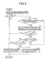
- Step S1 of the main routine of FIG. 3 the water temperature Tw of the cooling water of the engine is detected by the water temperature sensor Sa, if in Step S2 the water temperature Tw is at least a first set temperature T1 (e.g. 80°C), that is, warming up of the engine is completed or substantially completed and an idling rotational speed becomes low, it is determined that the running conditions of the engine are stabilized, and in Step S3 engagement of the lockup clutch LC is permitted.
- a first set temperature T1 e.g. 80°C
- Step S1 If in Step S1 above the water temperature Tw is less than the first set temperature T1 and in Step S4 the oil temperature sensor Sb is not malfunctioning, then in Step S5 the water temperature Tw of the cooling water of the engine is detected by the water temperature sensor Sa, and the oil temperature To of the hydraulic oil of the transmission is detected by the oil temperature sensor Sb. If in Step S6 the water temperature Tw is less than the first set temperature T1 and at least a second set temperature T2 (e.g. 60°C) and the oil temperature To is at least a third set temperature T3 (e.g. 50°C), then in Step S3 above engagement of the lockup clutch LC is permitted.
- a second set temperature T2 e.g. 60°C
- T3 e.g. 50°C
- Step S4 If in Step S4 above the oil temperature sensor Sb is malfunctioning, since it cannot be confirmed whether or not the oil temperature To is at least the third set temperature T3, in Step S9 engagement of the lockup clutch LC is restricted.
- Step S7 it is determined whether or not the running conditions of the vehicle are in the tight region of the lockup clutch LC, and if they are not in the tight region, then in Step S9 above engagement of the lockup clutch LC is restricted.
- the water temperature Tw is less than the second set temperature T2 but at least a fourth set temperature T4 (e.g. 30°C)
- Step S3 above engagement of the lockup clutch LC is permitted
- Step S9 above engagement of the lockup clutch LC is restricted.
- the tight region of the lockup clutch LC is a region in which the supplied oil pressure is fixed at a maximum value so that the lockup clutch LC is completely engaged, the engagement responsiveness thereof is hardly an issue, and there is therefore no problem even if the lockup clutch LC is engaged in a state in which the oil temperature To of the hydraulic oil is low and the viscosity is high.
- Step S11 Determination of the control region of the lockup clutch LC is carried out while the vehicle is being accelerated.
- Step S11 if not in an ON region (feedback region, tight region, and fixed region), in which the lockup clutch LC is engaged, then in Step S12 it is determined as being an OFF region, in which engagement of the lockup clutch LC is released. This determination is carried out based on the map shown in FIG. 5 , in which the vehicle speed V and the opening degree ⁇ of accelerator pedal are used as parameters.
- Step S 13 look up in the tight region map shown in FIG. 5 is carried out.
- the tight region map uses the vehicle speed V and the opening degree ⁇ of the accelerator pedal as parameters, and the tight region is set where the vehicle speed V and the opening degree ⁇ of the accelerator pedal are large.
- Step S14 a lower limit vehicle speed V0 for the tight region with the current opening degree ⁇ of the accelerator pedal is determined, and if the current vehicle speed V is at least the lower limit vehicle speed V0, then in Step S15 it is determined as being in the tight region.
- Step S16 look up in the fixed region map is carried out, and if in Step S17 the current opening degree ⁇ of the accelerator pedal is less than an upper limit opening degree ⁇ 0 of the accelerator pedal, then in Step S22 it is determined as being in the fixed region.
- Step S17 the current opening degree ⁇ of the accelerator pedal is less than an upper limit opening degree ⁇ 0 of the accelerator pedal
- Step S22 it is determined as being in the fixed region.
- the answer in Step S 17 above is NO, if in Step S18 the oil temperature sensor Sb is not malfunctioning and in Step S 19 the oil temperature To is at least a fifth set temperature T5 (e.g. 140°C), then in Step S20 it is determined as being in the OFF region, and if it is less than the fifth set temperature T5, then in Step S21 it is determined as being in the feedback region.
- T5 e.g. 140°C
- Step S18 above the oil temperature sensor Sb is malfunctioning and the oil temperature To is unknown, a feedback region, which corresponds to a time of normal running and for which the running frequency is high, is selected.
- the reason that being in the OFF region is determined when the oil temperature To is at least the fifth set temperature T5 is because in a state in which the oil temperature To is at least the fifth set temperature T5 an oil pressure cannot be generated due to the specification of the transmission.
- first to fifth set temperatures T1 to T5 in the embodiment are only examples, and should not be construed as being limited thereto.
Landscapes
- Engineering & Computer Science (AREA)
- Chemical & Material Sciences (AREA)
- Combustion & Propulsion (AREA)
- Mechanical Engineering (AREA)
- General Engineering & Computer Science (AREA)
- Transportation (AREA)
- Control Of Fluid Gearings (AREA)
- Hydraulic Clutches, Magnetic Clutches, Fluid Clutches, And Fluid Joints (AREA)
Abstract
Description
- The present invention relates to a control device for a lockup clutch that includes a lockup clutch of a torque converter disposed between an engine and a transmission, a temperature sensor that detects a water temperature of the engine or an oil temperature of the transmission, and engagement permission means that permits engagement of the lockup clutch when a temperature detected by the temperature sensor is at least a predetermined temperature.
- Engagement of a lockup clutch is normally permitted when the water temperature of cooling water of an engine is at least 80°C since, if the lockup clutch is engaged when the oil temperature of hydraulic oil of a transmission is low and the viscosity is high, there are problems such as vibration being generated due to engagement shock; an arrangement in which engagement of a lockup clutch is permitted when the water temperature is less than 80°C but at least 60°C and the oil temperature is at least 50°C to thus increase the frequency of engagement of the lockup clutch and improve the fuel economy is known from Patent Document 1 below.
- Patent Document 1: Japanese Patent Application Laid-open No.
2005-16616 - In accordance with the invention of Patent Document 1 above, it is possible to improve the fuel economy by increasing the frequency of engagement of the lockup clutch, but in order to achieve further improvement of the fuel economy it is necessary to further increase the frequency of engagement without affecting the function of the lockup clutch.
- The present invention has been accomplished in light of the above-mentioned circumstances, and it is an object thereof to further improve fuel economy by increasing the frequency of engagement of a lockup clutch without affecting the function thereof.
- In order to attain the above object, according to a first aspect of the present invention, there is provided a control device for a lockup clutch comprising a lockup clutch of a torque converter disposed between an engine and a transmission, a temperature sensor that detects a water temperature of the engine or an oil temperature of the transmission, and engagement permission means that permits engagement of the lockup clutch when a temperature detected by the temperature sensor is at least a predetermined temperature, characterized in that the device comprises control region determination means that determines whether or not the running conditions of a vehicle are in a tight region of the lockup clutch, and when the control region determination means determines that the running conditions of the vehicle are in the tight region, even if the temperature detected by the temperature sensor is less than the predetermined temperature, the engagement permission means permits engagement of the lockup clutch.
- Further, according to a second aspect of the present invention, in addition to the first aspect, the running conditions of the vehicle are a vehicle speed and an opening degree of an accelerator pedal, and the control region determination means determines that the running conditions of the vehicle are in the tight region when the vehicle speed is a predetermined value or greater and the opening degree of the accelerator pedal is a predetermined value or greater.
- A water temperature sensor Sa and an oil temperature sensor Sb of an embodiment correspond to the temperature sensor of the present invention.
- In accordance with the first aspect of the present invention, since, when the control region determination means determines that the running conditions of the vehicle are in the tight region of the lockup clutch, even if the water temperature of cooling water of the engine or the oil temperature of hydraulic oil of the transmission detected by the temperature sensor is less than a predetermined temperature, the engagement permission means permits engagement of the lockup clutch, it is possible to contribute to an improvement of the fuel economy by increasing the frequency of engagement of the lockup clutch. The reason is that in the tight region where the lockup clutch is completely engaged, the engagement responsiveness does not matter very much, and there is no problem even if the lockup clutch is engaged in a state in which the oil temperature of the hydraulic oil is low and the viscosity is high.
- Furthermore, in accordance with the second aspect of the present invention, since the control region determination means determines the tight region when the vehicle speed is the predetermined value or greater and the opening degree of the accelerator pedal is the predetermined value or greater, it is possible to determine the tight region with good precision.
-
- [
FIG. 1] FIG. 1 is a view showing the structure of a torque converter. (first embodiment) - [
FIG. 2] FIG. 2 is a block diagram of a control system. (first embodiment) - [
FIG. 3] FIG. 3 is a flowchart of a main routine. (first embodiment) - [
FIG. 4] FIG. 4 is a flowchart of a subroutine of Step S9 of the main routine. (first embodiment) - [
FIG. 5] FIG. 5 is a diagram showing a map in which an ON region and a tight region of the lockup clutch are looked up. (first embodiment) -
- TC Torque converter
- LC Lockup clutch
- Tw Water temperature of engine
- To Oil temperature of transmission
- Sa Water temperature sensor (temperature sensor)
- Sb Oil temperature sensor (temperature sensor)
- M2 Engagement permission means
- M3 Control region determination means
- V Vehicle speed
- θ Opening degree of accelerator pedal
- A mode for carrying out the present invention is explained below by reference to
FIG. 1 to FIG. 5 . - As shown in
FIG. 1 , a torque converter TC provided in an automatic transmission of an automobile includes animpeller 12 that is connected to a crankshaft (not illustrated) of an engine via atorque converter cover 11, aturbine 13 that is disposed so as to oppose theimpeller 12 and is connected to an input shaft (not illustrated) of the transmission, and astator 15 that is disposed between theimpeller 12 and theturbine 13 and is supported on a fixing part via a one-way clutch 14. A lockup clutch LC that joins theimpeller 12 to theturbine 13 includes alockup piston 16 that is disposed in a space between a back face of theturbine 13 and thetorque converter cover 11, the space being divided by thelockup piston 16 into alockup release chamber 17 on thetorque converter cover 11 side and alockup tightening chamber 18 on theturbine 13 side. Thelockup piston 16 can slide in the axial direction of the torque converter TC and can rotate together with theturbine 13. - The interior of the torque converter TC is filled with hydraulic oil supplied from a lockup
release chamber inlet 19 and a lockuptightening chamber inlet 20, and when theimpeller 12 is rotated by the crankshaft of the engine via thetorque converter cover 11 to make the hydraulic oil circulate, theturbine 13 receives the dynamic pressure and is driven, and the input shaft of the transmission rotates. In this process, due to the action of blades of theimpeller 12, theturbine 13, and thestator 15 the torque of theimpeller 12 is amplified and transmitted to theturbine 13, but even under running conditions in which theimpeller 12 and theturbine 13 rotate at the same speed, since power transmission is via hydraulic oil, it is impossible to avoid the occurrence of a certain degree of power transmission loss. Therefore, the lockup clutch LC is engaged to integrally join theimpeller 12 and theturbine 13, and the occurrence of power transmission loss is thus avoided. - Engagement and disengagement of the lockup clutch LC is carried out by supplying an oil pressure selectively to the
lockup release chamber 17 and thelockup tightening chamber 18. That is, when an oil pressure is supplied from the lockup tightening chamber inlet 20 to the lockup tightening chamber 18 afriction material 21 of thelockup piston 16 abuts against thetorque converter cover 11 to thus engage the lockup clutch LC, and rotation of the crankshaft is transmitted directly to the input shaft via thetorque converter cover 11 and thelockup piston 16. On the other hand, when an oil pressure is supplied from the lockup release chamber inlet 19 to thelockup release chamber 17 thefriction material 21 of thelockup piston 16 becomes detached from thetorque converter cover 11 to thus release engagement of the lockup clutch LC, and rotation of the crankshaft is transmitted to the input shaft via thetorque converter cover 11, theimpeller 12, the hydraulic oil, and theturbine 13. - A lockup clutch control device that controls engagement and disengagement of the lockup clutch LC includes a
hydraulic pump 23 that supplies hydraulic oil within ahydraulic oil tank 22, supply pressure adjustment means 24 that adjusts the pressure of the hydraulic oil supplied from thehydraulic pump 23, hydraulic circuit switching means 25 that selectively supplies the pressure-adjusted oil pressure to thelockup release chamber 17 and thelockup tightening chamber 18, tightening force adjustment means 26 that controls the oil pressure supplied to thelockup release chamber 17, and signal pressure generation means 27 that generates a signal pressure for controlling the tightening force control means 26. Therefore, it is possible to control the oil pressure of thelockup release chamber 17 by the tightening force adjustment means 26, control the oil pressure of thelockup tightening chamber 18 by the supply pressure adjustment means 24, and carry out switching control of the supplied oil pressure by the hydraulic circuit switching means 25, thereby enabling the tightening force of the lockup clutch LC to be freely controlled. - In a state in which an oil temperature To of the hydraulic oil of the transmission is low, the viscosity of the hydraulic oil becomes high and operation of the lockup clutch LC becomes unstable, and it is therefore necessary to restrict engagement of the lockup clutch LC. Furthermore, in a state in which a water temperature Tw of cooling water of the engine before warming up is complete is low, the idling rotational speed is set high, and it is therefore necessary to restrict engagement of the lockup clutch LC. In this process, if engagement of the lockup clutch LC is restricted unnecessarily, it might cause degradation of the fuel economy, and it is therefore desirable to minimize restrictions on the engagement of the lockup clutch LC.
- Because of this, in the present embodiment, as shown in
FIG. 2 , an electronic control unit U that controls engagement and disengagement of the lockup clutch LC includes temperature comparison means M1, engagement permission means M2, and control region determination means M3. Connected to the temperature comparison means M1 are a water temperature sensor Sa that detects the water temperature Tw of the cooling water of the engine and an oil temperature sensor Sb that detects the oil temperature To of the hydraulic oil of the transmission. Connected to the control region determination means M3 are a vehicle speed sensor Sc that detects a vehicle speed V and an accelerator pedal opening degree sensor Sd that detects an opening degree θ of an accelerator pedal. - The temperature comparison means M1 compares the water temperature Tw and the oil temperature To with predetermined threshold values, and based on the results thereof the engagement permission means M2 permits engagement of the lockup clutch LC. The control region determination means M3 determines, based on the vehicle speed V and the opening degree θ of the accelerator pedal, a control region for controlling engagement of the lockup clutch LC, that is, a feedback region, a tight region, and a fixed region. As shown in
FIG. 5 , the feedback region is a region in which oil pressure supplied to the lockup clutch LC is subjected to feedback control so that the slip rate of the lockup clutch LC becomes a predetermined value. The tight region is a region in which oil pressure supplied to the lockup clutch LC is fixed to a maximum value so that the lockup clutch LC is completely engaged. The fixed region is a region in which there is no target slip rate, and feedforward control of supplying a precalculated oil pressure to the lockup clutch LC is carried out. - The operation is now explained in further detail by reference to
FIG. 2 and the flowchart ofFIG. 3 . - First, in Step S1 of the main routine of
FIG. 3 the water temperature Tw of the cooling water of the engine is detected by the water temperature sensor Sa, if in Step S2 the water temperature Tw is at least a first set temperature T1 (e.g. 80°C), that is, warming up of the engine is completed or substantially completed and an idling rotational speed becomes low, it is determined that the running conditions of the engine are stabilized, and in Step S3 engagement of the lockup clutch LC is permitted. - If in Step S1 above the water temperature Tw is less than the first set temperature T1 and in Step S4 the oil temperature sensor Sb is not malfunctioning, then in Step S5 the water temperature Tw of the cooling water of the engine is detected by the water temperature sensor Sa, and the oil temperature To of the hydraulic oil of the transmission is detected by the oil temperature sensor Sb. If in Step S6 the water temperature Tw is less than the first set temperature T1 and at least a second set temperature T2 (e.g. 60°C) and the oil temperature To is at least a third set temperature T3 (e.g. 50°C), then in Step S3 above engagement of the lockup clutch LC is permitted.
- At the second set temperature T2 (= 60°C), which is lower than the first set temperature T1 (= 80°C), the state is one in which warming up of the engine is not yet completed and the idling rotational speed is high to some degree. The third set temperature T3 (= 50°C) is a lower limit value of the oil temperature To that can give a viscosity of the hydraulic oil that is necessary for stable engagement of the lockup clutch LC, and if the oil temperature To is at least the third set temperature T3, the viscosity of the hydraulic oil becomes sufficiently low, and it becomes possible to prevent generation of vibration, etc. due to shock when the lockup clutch LC is engaged.
- In this way, even in a state in which the idling rotational speed of the engine is slightly higher than the rotational speed after warming up is completed, that is, in a state in which the water temperature Tw is less than the first set temperature T1 and at least the second set temperature T2, when the oil temperature To is at least the third set temperature T3 and the viscosity of the hydraulic oil becomes sufficiently low, permitting engagement of the lockup clutch LC enables the frequency of engagement of the lockup clutch LC to be increased, thus improving the fuel economy.
- If in Step S4 above the oil temperature sensor Sb is malfunctioning, since it cannot be confirmed whether or not the oil temperature To is at least the third set temperature T3, in Step S9 engagement of the lockup clutch LC is restricted.
- In the case in which the answer in Step S6 above is NO and engagement of the lockup clutch LC is not permitted, in Step S7 it is determined whether or not the running conditions of the vehicle are in the tight region of the lockup clutch LC, and if they are not in the tight region, then in Step S9 above engagement of the lockup clutch LC is restricted. On the other hand, if in Step S7 above they are in the tight region and in Step S8 the water temperature Tw is less than the second set temperature T2 but at least a fourth set temperature T4 (e.g. 30°C), then in Step S3 above engagement of the lockup clutch LC is permitted, and if the answer in Step S8 above is NO, then in Step S9 above engagement of the lockup clutch LC is restricted.
- Since the tight region of the lockup clutch LC is a region in which the supplied oil pressure is fixed at a maximum value so that the lockup clutch LC is completely engaged, the engagement responsiveness thereof is hardly an issue, and there is therefore no problem even if the lockup clutch LC is engaged in a state in which the oil temperature To of the hydraulic oil is low and the viscosity is high.
- Determination of the control region of the lockup clutch LC is now explained by reference to the flowchart of
FIG. 4 . - Determination of the control region of the lockup clutch LC is carried out while the vehicle is being accelerated. First, in Step S11, if not in an ON region (feedback region, tight region, and fixed region), in which the lockup clutch LC is engaged, then in Step S12 it is determined as being an OFF region, in which engagement of the lockup clutch LC is released. This determination is carried out based on the map shown in
FIG. 5 , in which the vehicle speed V and the opening degree θ of accelerator pedal are used as parameters. - If in Step S11 above they are in the ON region of the lockup clutch LC, then in
Step S 13 look up in the tight region map shown inFIG. 5 is carried out. The tight region map uses the vehicle speed V and the opening degree θ of the accelerator pedal as parameters, and the tight region is set where the vehicle speed V and the opening degree θ of the accelerator pedal are large. In Step S14 a lower limit vehicle speed V0 for the tight region with the current opening degree θ of the accelerator pedal is determined, and if the current vehicle speed V is at least the lower limit vehicle speed V0, then in Step S15 it is determined as being in the tight region. - If the answer in Step S14 above is NO, in Step S16 look up in the fixed region map is carried out, and if in Step S17 the current opening degree θ of the accelerator pedal is less than an upper limit opening degree θ0 of the accelerator pedal, then in Step S22 it is determined as being in the fixed region. When the answer in
Step S 17 above is NO, if in Step S18 the oil temperature sensor Sb is not malfunctioning and inStep S 19 the oil temperature To is at least a fifth set temperature T5 (e.g. 140°C), then in Step S20 it is determined as being in the OFF region, and if it is less than the fifth set temperature T5, then in Step S21 it is determined as being in the feedback region. Furthermore, if in Step S18 above the oil temperature sensor Sb is malfunctioning and the oil temperature To is unknown, a feedback region, which corresponds to a time of normal running and for which the running frequency is high, is selected. The reason that being in the OFF region is determined when the oil temperature To is at least the fifth set temperature T5 is because in a state in which the oil temperature To is at least the fifth set temperature T5 an oil pressure cannot be generated due to the specification of the transmission. - As described above, when the water temperature T is less than the second set temperature T2 (60°C) but at least the fourth set temperature T4 (30°C), engagement of the lockup clutch LC is conventionally restricted, but in the present embodiment engagement of the lockup clutch LC is permitted provided that the running conditions of the vehicle are in the tight region and the engagement responsiveness of the lockup clutch LC is not an issue, and it is therefore possible to contribute to an improvement of the fuel economy by increasing the frequency of engagement of the lockup clutch LC.
- An embodiment of the present invention is explained above, but the present invention may be modified in a variety of ways as long as the modifications do not depart from the spirit and scope thereof.
- For example, the first to fifth set temperatures T1 to T5 in the embodiment are only examples, and should not be construed as being limited thereto.
Claims (2)
- A control device for a lockup clutch comprising
a lockup clutch (LC) of a torque converter (TC) disposed between an engine and a transmission,
a temperature sensor (Sa, Sb) that detects a water temperature (Tw) of the engine or an oil temperature (To) of the transmission, and
engagement permission means (M2) that permits engagement of the lockup clutch (LC) when a temperature detected by the temperature sensor (Sa, Sb) is at least a predetermined temperature,
characterized in that the device comprises control region determination means (M3) that determines whether or not the running conditions of a vehicle are in a tight region of the lockup clutch (LC), and
when the control region determination means (M3) determines that the running conditions of the vehicle are in the tight region, even if the temperature detected by the temperature sensor (Sa, Sb) is less than the predetermined temperature, the engagement permission means (M2) permits engagement of the lockup clutch (LC). - The control device for a lockup clutch according to Claim 1, wherein the running conditions of the vehicle are a vehicle speed (V) and an opening degree (θ) of an accelerator pedal, and the control region determination means (M3) determines that the running conditions of the vehicle are in the tight region when the vehicle speed (V) is a predetermined value or greater and the opening degree (θ) of the accelerator pedal is a predetermined value or greater.
Applications Claiming Priority (2)
| Application Number | Priority Date | Filing Date | Title |
|---|---|---|---|
| JP2011043567 | 2011-03-01 | ||
| PCT/JP2012/053960 WO2012117880A1 (en) | 2011-03-01 | 2012-02-20 | Control device for lockup clutch |
Publications (2)
| Publication Number | Publication Date |
|---|---|
| EP2682647A1 true EP2682647A1 (en) | 2014-01-08 |
| EP2682647A4 EP2682647A4 (en) | 2014-10-29 |
Family
ID=46757819
Family Applications (1)
| Application Number | Title | Priority Date | Filing Date |
|---|---|---|---|
| EP12752835.4A Withdrawn EP2682647A4 (en) | 2011-03-01 | 2012-02-20 | CONTROL DEVICE FOR BLOCK CLUTCH |
Country Status (6)
| Country | Link |
|---|---|
| US (1) | US9108619B2 (en) |
| EP (1) | EP2682647A4 (en) |
| JP (1) | JP5638120B2 (en) |
| CN (1) | CN103380318B (en) |
| BR (1) | BR112013021914A2 (en) |
| WO (1) | WO2012117880A1 (en) |
Families Citing this family (5)
| Publication number | Priority date | Publication date | Assignee | Title |
|---|---|---|---|---|
| KR101878028B1 (en) * | 2016-03-18 | 2018-07-16 | 현대자동차주식회사 | Overheat preventing method of clutch for vehicle |
| JP7310671B2 (en) * | 2020-03-23 | 2023-07-19 | トヨタ自動車株式会社 | Exhaust purification device for internal combustion engine |
| CN111810630A (en) * | 2020-07-22 | 2020-10-23 | 河南科技大学 | A control system and control method suitable for hydraulic coupling transmission |
| US11618452B2 (en) * | 2021-04-29 | 2023-04-04 | Toyota Motor Engineering & Manufacturing North America, Inc. | Powertrain torque limitation to ensure lock-up clutch engagement during high temperature transmission fluid condition |
| CN115773362B (en) * | 2022-11-11 | 2024-12-27 | 中国第一汽车股份有限公司 | Transmission gear shifting control method and device and vehicle |
Family Cites Families (17)
| Publication number | Priority date | Publication date | Assignee | Title |
|---|---|---|---|---|
| EP0037050A3 (en) * | 1980-03-27 | 1984-05-09 | Nissan Motor Co., Ltd. | Lock-up control system for lock-up type automatic transmission |
| JPH06100275B2 (en) * | 1988-05-09 | 1994-12-12 | 本田技研工業株式会社 | Control method for direct coupling mechanism of fluid power transmission device |
| JPH03260463A (en) * | 1990-03-07 | 1991-11-20 | Mazda Motor Corp | Control device for automatic transmission |
| JP3422519B2 (en) * | 1993-05-14 | 2003-06-30 | ジヤトコ株式会社 | Lockup control device for automatic transmission |
| JP3152073B2 (en) * | 1994-07-22 | 2001-04-03 | トヨタ自動車株式会社 | Slip control device for vehicle lock-up clutch |
| US5722912A (en) * | 1995-08-30 | 1998-03-03 | Honda Giken Kogyo Kabushiki Kaisha | Lock-up control system for automatic transmissions |
| JP3900587B2 (en) * | 1997-04-14 | 2007-04-04 | マツダ株式会社 | Fastening force control device for fluid coupling of vehicle with automatic transmission |
| JP3698529B2 (en) * | 1997-09-29 | 2005-09-21 | 本田技研工業株式会社 | Lock-up clutch control device |
| JP2001099305A (en) * | 1999-09-30 | 2001-04-10 | Nissan Motor Co Ltd | Lockup control device for automatic transmission |
| JP4191968B2 (en) * | 2002-08-27 | 2008-12-03 | トヨタ自動車株式会社 | Vehicle drive control device |
| JP4274858B2 (en) | 2003-06-25 | 2009-06-10 | 本田技研工業株式会社 | Control device for torque converter with lock-up mechanism |
| JP2005030484A (en) * | 2003-07-11 | 2005-02-03 | Nissan Motor Co Ltd | Automatic transmission control device |
| JP4133989B2 (en) * | 2004-10-01 | 2008-08-13 | ジヤトコ株式会社 | Control device for continuously variable transmission |
| JP4941139B2 (en) * | 2007-07-09 | 2012-05-30 | トヨタ自動車株式会社 | Control device for lock-up clutch |
| JP4577342B2 (en) * | 2007-09-10 | 2010-11-10 | トヨタ自動車株式会社 | Hydraulic control device |
| CN102066813B (en) * | 2008-07-04 | 2014-01-15 | 本田技研工业株式会社 | Line pressure controller for automatic transmission |
| JP4896184B2 (en) * | 2009-06-09 | 2012-03-14 | 本田技研工業株式会社 | Control device for lock-up clutch |
-
2012
- 2012-02-20 JP JP2013502246A patent/JP5638120B2/en not_active Expired - Fee Related
- 2012-02-20 BR BR112013021914A patent/BR112013021914A2/en not_active IP Right Cessation
- 2012-02-20 EP EP12752835.4A patent/EP2682647A4/en not_active Withdrawn
- 2012-02-20 WO PCT/JP2012/053960 patent/WO2012117880A1/en not_active Ceased
- 2012-02-20 CN CN201280008987.0A patent/CN103380318B/en not_active Expired - Fee Related
- 2012-02-20 US US13/985,400 patent/US9108619B2/en active Active
Also Published As
| Publication number | Publication date |
|---|---|
| BR112013021914A2 (en) | 2016-11-08 |
| JPWO2012117880A1 (en) | 2014-07-07 |
| US20140080671A1 (en) | 2014-03-20 |
| CN103380318B (en) | 2016-03-09 |
| CN103380318A (en) | 2013-10-30 |
| US9108619B2 (en) | 2015-08-18 |
| WO2012117880A1 (en) | 2012-09-07 |
| EP2682647A4 (en) | 2014-10-29 |
| JP5638120B2 (en) | 2014-12-10 |
Similar Documents
| Publication | Publication Date | Title |
|---|---|---|
| US10023196B2 (en) | Control device for vehicle | |
| US9108619B2 (en) | Control device for lockup clutch | |
| RU2716055C2 (en) | Method for vehicle (embodiments) | |
| KR101713738B1 (en) | A hydraulic control apparatus for hydraulic torque converter | |
| US8979706B2 (en) | Control device and control method for lockup clutch | |
| US9815466B2 (en) | Lock-up clutch control device for vehicle | |
| KR101551589B1 (en) | Device for controlling automatic transmission | |
| JP6137199B2 (en) | Control device and control method for lock-up clutch | |
| KR20110097705A (en) | Oil temperature correction device of automatic transmission | |
| US20040103862A1 (en) | Engine temperature control apparatus and method | |
| JP2004286148A (en) | Control method and control device for automatic transmission | |
| JP2007247910A (en) | Hydraulic pressure supply device | |
| US7255214B2 (en) | Damper lock-out clutch and motor/generator cooling multiplexed control system and method for an electrically variable hybrid transmissions | |
| US20150369361A1 (en) | Vehicle control device | |
| JPWO2013145971A1 (en) | Hydraulic control circuit and control method thereof | |
| US11565686B2 (en) | Hybrid vehicle control apparatus | |
| US8574124B2 (en) | Control unit and method to operate a vehicle | |
| JP4274858B2 (en) | Control device for torque converter with lock-up mechanism | |
| JP5500264B2 (en) | Internal combustion engine cooling system | |
| JP2014173617A (en) | Clutch control device | |
| WO2014112603A1 (en) | Lock-up-clutch control device and control method | |
| KR101575281B1 (en) | Method for controlling electric oil pump of vehicle | |
| JP6568003B2 (en) | Automatic transmission | |
| JP7658301B2 (en) | Vehicle control device | |
| US10449950B2 (en) | Control apparatus for vehicle and control method for vehicle |
Legal Events
| Date | Code | Title | Description |
|---|---|---|---|
| PUAI | Public reference made under article 153(3) epc to a published international application that has entered the european phase |
Free format text: ORIGINAL CODE: 0009012 |
|
| 17P | Request for examination filed |
Effective date: 20130829 |
|
| AK | Designated contracting states |
Kind code of ref document: A1 Designated state(s): AL AT BE BG CH CY CZ DE DK EE ES FI FR GB GR HR HU IE IS IT LI LT LU LV MC MK MT NL NO PL PT RO RS SE SI SK SM TR |
|
| DAX | Request for extension of the european patent (deleted) | ||
| A4 | Supplementary search report drawn up and despatched |
Effective date: 20140930 |
|
| RIC1 | Information provided on ipc code assigned before grant |
Ipc: F16H 61/14 20060101AFI20140924BHEP |
|
| GRAP | Despatch of communication of intention to grant a patent |
Free format text: ORIGINAL CODE: EPIDOSNIGR1 |
|
| STAA | Information on the status of an ep patent application or granted ep patent |
Free format text: STATUS: GRANT OF PATENT IS INTENDED |
|
| INTG | Intention to grant announced |
Effective date: 20190222 |
|
| STAA | Information on the status of an ep patent application or granted ep patent |
Free format text: STATUS: THE APPLICATION IS DEEMED TO BE WITHDRAWN |
|
| 18D | Application deemed to be withdrawn |
Effective date: 20190705 |