EP2682639A1 - Damper with variable damping force - Google Patents
Damper with variable damping force Download PDFInfo
- Publication number
- EP2682639A1 EP2682639A1 EP12752888.3A EP12752888A EP2682639A1 EP 2682639 A1 EP2682639 A1 EP 2682639A1 EP 12752888 A EP12752888 A EP 12752888A EP 2682639 A1 EP2682639 A1 EP 2682639A1
- Authority
- EP
- European Patent Office
- Prior art keywords
- valve element
- communicating channel
- valve seat
- opening
- chamber
- Prior art date
- Legal status (The legal status is an assumption and is not a legal conclusion. Google has not performed a legal analysis and makes no representation as to the accuracy of the status listed.)
- Withdrawn
Links
- 238000013016 damping Methods 0.000 title claims abstract description 70
- 230000002093 peripheral effect Effects 0.000 claims description 6
- 125000006850 spacer group Chemical group 0.000 claims description 3
- 239000007788 liquid Substances 0.000 description 14
- 239000000463 material Substances 0.000 description 6
- 230000000694 effects Effects 0.000 description 5
- XEEYBQQBJWHFJM-UHFFFAOYSA-N Iron Chemical compound [Fe] XEEYBQQBJWHFJM-UHFFFAOYSA-N 0.000 description 4
- 238000004519 manufacturing process Methods 0.000 description 4
- 238000012856 packing Methods 0.000 description 4
- 239000000470 constituent Substances 0.000 description 3
- 239000000565 sealant Substances 0.000 description 3
- 238000004891 communication Methods 0.000 description 2
- 238000010276 construction Methods 0.000 description 2
- 230000001747 exhibiting effect Effects 0.000 description 2
- 229910052742 iron Inorganic materials 0.000 description 2
- 239000000696 magnetic material Substances 0.000 description 2
- 230000035699 permeability Effects 0.000 description 2
- 230000000630 rising effect Effects 0.000 description 2
- 230000002159 abnormal effect Effects 0.000 description 1
- XAGFODPZIPBFFR-UHFFFAOYSA-N aluminium Chemical compound [Al] XAGFODPZIPBFFR-UHFFFAOYSA-N 0.000 description 1
- 229910052782 aluminium Inorganic materials 0.000 description 1
- 238000013459 approach Methods 0.000 description 1
- 238000010030 laminating Methods 0.000 description 1
- 238000005192 partition Methods 0.000 description 1
- 230000000149 penetrating effect Effects 0.000 description 1
- 239000011347 resin Substances 0.000 description 1
- 229920005989 resin Polymers 0.000 description 1
Images




Classifications
-
- F—MECHANICAL ENGINEERING; LIGHTING; HEATING; WEAPONS; BLASTING
- F16—ENGINEERING ELEMENTS AND UNITS; GENERAL MEASURES FOR PRODUCING AND MAINTAINING EFFECTIVE FUNCTIONING OF MACHINES OR INSTALLATIONS; THERMAL INSULATION IN GENERAL
- F16F—SPRINGS; SHOCK-ABSORBERS; MEANS FOR DAMPING VIBRATION
- F16F9/00—Springs, vibration-dampers, shock-absorbers, or similarly-constructed movement-dampers using a fluid or the equivalent as damping medium
- F16F9/10—Springs, vibration-dampers, shock-absorbers, or similarly-constructed movement-dampers using a fluid or the equivalent as damping medium using liquid only; using a fluid of which the nature is immaterial
- F16F9/14—Devices with one or more members, e.g. pistons, vanes, moving to and fro in chambers and using throttling effect
- F16F9/16—Devices with one or more members, e.g. pistons, vanes, moving to and fro in chambers and using throttling effect involving only straight-line movement of the effective parts
- F16F9/18—Devices with one or more members, e.g. pistons, vanes, moving to and fro in chambers and using throttling effect involving only straight-line movement of the effective parts with a closed cylinder and a piston separating two or more working spaces therein
-
- F—MECHANICAL ENGINEERING; LIGHTING; HEATING; WEAPONS; BLASTING
- F16—ENGINEERING ELEMENTS AND UNITS; GENERAL MEASURES FOR PRODUCING AND MAINTAINING EFFECTIVE FUNCTIONING OF MACHINES OR INSTALLATIONS; THERMAL INSULATION IN GENERAL
- F16F—SPRINGS; SHOCK-ABSORBERS; MEANS FOR DAMPING VIBRATION
- F16F9/00—Springs, vibration-dampers, shock-absorbers, or similarly-constructed movement-dampers using a fluid or the equivalent as damping medium
- F16F9/10—Springs, vibration-dampers, shock-absorbers, or similarly-constructed movement-dampers using a fluid or the equivalent as damping medium using liquid only; using a fluid of which the nature is immaterial
- F16F9/14—Devices with one or more members, e.g. pistons, vanes, moving to and fro in chambers and using throttling effect
- F16F9/16—Devices with one or more members, e.g. pistons, vanes, moving to and fro in chambers and using throttling effect involving only straight-line movement of the effective parts
- F16F9/18—Devices with one or more members, e.g. pistons, vanes, moving to and fro in chambers and using throttling effect involving only straight-line movement of the effective parts with a closed cylinder and a piston separating two or more working spaces therein
- F16F9/185—Bitubular units
- F16F9/187—Bitubular units with uni-directional flow of damping fluid through the valves
-
- F—MECHANICAL ENGINEERING; LIGHTING; HEATING; WEAPONS; BLASTING
- F16—ENGINEERING ELEMENTS AND UNITS; GENERAL MEASURES FOR PRODUCING AND MAINTAINING EFFECTIVE FUNCTIONING OF MACHINES OR INSTALLATIONS; THERMAL INSULATION IN GENERAL
- F16F—SPRINGS; SHOCK-ABSORBERS; MEANS FOR DAMPING VIBRATION
- F16F9/00—Springs, vibration-dampers, shock-absorbers, or similarly-constructed movement-dampers using a fluid or the equivalent as damping medium
- F16F9/32—Details
- F16F9/3207—Constructional features
- F16F9/3235—Constructional features of cylinders
- F16F9/325—Constructional features of cylinders for attachment of valve units
-
- F—MECHANICAL ENGINEERING; LIGHTING; HEATING; WEAPONS; BLASTING
- F16—ENGINEERING ELEMENTS AND UNITS; GENERAL MEASURES FOR PRODUCING AND MAINTAINING EFFECTIVE FUNCTIONING OF MACHINES OR INSTALLATIONS; THERMAL INSULATION IN GENERAL
- F16F—SPRINGS; SHOCK-ABSORBERS; MEANS FOR DAMPING VIBRATION
- F16F9/00—Springs, vibration-dampers, shock-absorbers, or similarly-constructed movement-dampers using a fluid or the equivalent as damping medium
- F16F9/32—Details
- F16F9/44—Means on or in the damper for manual or non-automatic adjustment; such means combined with temperature correction
- F16F9/46—Means on or in the damper for manual or non-automatic adjustment; such means combined with temperature correction allowing control from a distance, i.e. location of means for control input being remote from site of valves, e.g. on damper external wall
- F16F9/466—Throttling control, i.e. regulation of flow passage geometry
Definitions
- the present invention relates to a damper with variable damping force, the damping force of which can be variably controlled.
- a valve element which is arranged in a flow channel between a reservoir and a cylinder containing a piston is opened or closed by an electromagnetic solenoid actuator so as to change the damping force of the damper.
- a valve element which is arranged in a flow channel formed in a piston contained in a cylinder is opened or closed by electromagnetic attractive force generated by an electromagnetic solenoid so as to change the damping force of the damper.
- the valve element is directly brought into contact by the electromagnetic solenoid
- the construction of the damper with variable damping force disclosed in Patent document 2 is simple, and the number of the constituent parts of the damper with variable damping force disclosed in Patent document 2 is small. Therefore, the manufacturing cost of the damper with variable damping force disclosed in Patent document 2 can be lowered.
- the electromagnetic force (attractive force) generated by the electromagnetic solenoid is inversely proportional to the square of the distance.
- the object of the present invention is to provide a damper with variable damping force which has a simple structure and can suppress the power consumption.
- An aspect of the present invention provides a damper with variable damping force comprising:
- the damper with variable damping force includes the inner and outer cylinders, the piston, the reservoir chamber, and the damping-force control device which includes the valve seat, the valve element, and the cap. Therefore, the damping-force control device and the damper with variable damping force can be constructed to have a simple structure. In addition, since the number of parts can be reduced, the manufacturing cost is lowered.
- the valve element comes into contact with the cap when the extent of opening of the valve element increases. Therefore, the increase in the extent of opening can be suppressed, and the electromagnetic solenoid can attract the valve element and close the valve even when the electromagnetic force is small. Consequently, the power consumption can be reduced.
- the first communicating channel communicates the second communicating channel through an opening of the valve element in a state in which the valve element is open, and an biasing force which impels the valve element to a direction of closing the valve element is exerted on the valve element by a differential pressure generated between a front side and a back side of the valve element when the operating oil flows.
- the flow channel from the first communication channel to the second communication channel in the variable pressure chamber is formed to pass the side of the valve element opposite to the valve seat, and the operating oil flowing through the flow channel applies to the valve element a pressure in a direction of closing the valve. Therefore, it is possible to prevent the valve element from coming apart from the electromagnetic solenoid, and thus close the valve with a small electromagnetic force. Consequently, the power consumption can be reduced.
- valve element comprises,
- a flow channel of a flow from the opening for the first communicating channel through the first hole and the side of the valve element opposite to the valve seat can be formed in the variable pressure chamber.
- This flow channel further passes through the second hole and reaches the opening for the second communicating channel. Since the first hole is more apart from the support portion than the second hole, the portion of the valve element in the vicinity of the second hole is more close to the valve seat than the portion of the valve element in the vicinity of the first hole. Therefore, when the operating oil flows from the variable pressure chamber to the second communicating channel, the damping force is generated by the second hole, which is close to the valve seat (the opening for the second communicating channel).
- the inner pressure on the side of the valve element opposite to the valve seat in the variable pressure chamber becomes higher than the inner pressure in the second communicating channel (on the valve seat side of the valve element in the variable pressure chamber), so that a force in the direction of closing the valve is generated.
- the damper with variable damping force further comprises a spacer arranged between the valve element and the valve seat to provide an intermediate channel through which the first communicating channel communicates with the second communicating channel without passing through the valve element.
- the damper with variable damping force has the above feature, even when a rapid stroke or the like occurs, it is possible to suppress the driving force of the valve element and prevent a rapid rise of the damping force.
- a damper with variable damping force which has a simple structure and can suppress the power consumption.
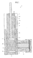
- FIG. 1 is a longitudinal cross-sectional view of a damper 1 with variable damping force according to a first embodiment of the present invention.
- a piston 3 is slidably fitted into a cylinder 2, i.e., the piston 3 is in slidable contact with the cylinder 2, where the cylinder 2 is filled with an operating oil 5.
- An upper chamber (inner chamber) 2a is defined by the cylinder 2 and the piston 3, and an end of a piston rod 3a is connected to the piston 3.
- the piston rod 3a extends across the upper chamber 2a and passes through an upper end portion of the cylinder 2 and a buffer member 2d.
- the piston rod 3a is slidably fitted into the upper end portion of the cylinder 2 and the buffer member 2d without leakage of the operating oil 5 outside.
- a bottom valve 4 is arranged below the piston 3 in the cylinder 2.
- a check valve 4a is arranged in the bottom valve 4. The check valve 4a allows the operating oil 5 to flow from a reservoir chamber 7 through a through hole 2f and a lower chamber 2c to a middle chamber 2b, and does not allow the operating oil 5 to flow from the middle chamber 2b to the reservoir chamber 7.
- the bottom valve 4 (the check valve 4a) may be arranged at the through hole 2f.
- a check valve 3b is arranged in the piston 3. The check valve 3b allows the operating oil 5 to flow from the middle chamber 2b to the upper chamber (inner chamber) 2a, and does not allow the operating oil 5 to flow from the upper chamber (inner chamber) 2a to the middle chamber 2b.
- An outer cylinder 8 is arranged outside the cylinder 2.
- the reservoir chamber 7 is defined by the cylinder 2 and the outer cylinder 8.
- the reservoir chamber 7 is filled with the operating oil 5 and a gas.
- the reservoir chamber 7 is connected to the middle chamber 2b through the bottom valve 4, which is arranged in the lower portion of the cylinder 2.
- a through hole 2e is arranged in the upper portion of the cylinder 2.
- the upper chamber (inner chamber) 2a is connected to an upper portion of an intermediate oil channel 6 through the through hole 2e.
- the intermediate oil channel 6 is arranged outside the cylinder 2 inside the outer cylinder 8 and defined by a portion of the side wall of the cylinder 2.
- the intermediate oil channel 6 is arranged along the axis direction of the cylinder 2, and the lower portion of the intermediate oil channel 6 is connected to a damping-force control device 9.
- the damping-force control device 9 is arranged outside the lower portion of the outer cylinder 8, and connected to the lower portion of the reservoir chamber 7 in the lower portion of the outer cylinder 8.
- the upper chamber (inner chamber) 2a is connected through the through hole 2e, the intermediate oil channel 6, and the damping-force control device 9 to the lower portion of the reservoir chamber 7 in this order, and is further connected through the through hole 2f and the bottom valve 4 to the middle chamber 2b.
- the upper portion of the intermediate oil channel 6 is connected to the upper chamber (inner chamber) 2a, and the lower portion of the intermediate oil channel 6 is connected to the damping-force control device 9.
- the damping-force control device 9 is connected to the upper chamber (inner chamber) 2a through the intermediate oil channel 6, and to the reservoir chamber 7.
- the damping-force control device 9 controls the damping force generated by the damper 1 with variable damping force, by controlling the flow rate of the operating oil 5 through the intermediate oil channel 6, i.e., by controlling the flow rate of the operating oil 5 flowing from the intermediate oil channel 6 into the damping-force control device 9.
- the piston 3a When the piston rod 3a is drawn out of the cylinder 2 in the damper 1 with variable damping force, the piston 3 is raised with the piston rod 3a, and the volume of the upper chamber (inner chamber) 2a is reduced.
- the operating oil 5 in the upper chamber (inner chamber) 2a flows through the through hole 2e and the intermediate oil channel 6 to the damping-force control device 9. Further, the operating oil 5 flows out of the damping-force control device 9 to the reservoir chamber 7, so that the liquid level of the operating oil 5 in the reservoir chamber 7 is raised, and the gas above the liquid level is compressed. Furthermore, the operating oil 5 flows out of the reservoir chamber 7 through the bottom valve 4 (the check valve 4a) to the middle chamber 2b.
- the operating oil 5 flows out of the upper chamber (inner chamber) 2a through the intermediate oil channel 6 to the damping-force control device 9, and further flows from the damping-force control device 9 to the reservoir chamber 7.
- the operating oil 5 in the damping-force control device 9 always unidirectionally flows in a direction from the intermediate oil channel 6 into the damping-force control device 9 and from the damping-force control device 9 to the reservoir chamber 7.
- FIG. 2 is a longitudinal cross-sectional view of the damping-force control device 9 arranged in the damper with variable damping force according to the first embodiment of the present invention.
- the damping-force control device 9 includes a valve seat 11 having a cylindrical post shape.
- An electromagnetic solenoid 14 is embedded in the valve seat 11 along the circular periphery of the cylindrical post shape of the valve seat 11. It is preferable that a soft magnetic material exhibiting a low hysteresis (having a small coercive force) and having a great magnetic permeability, such as soft iron, be used in the valve seat 11.
- a first communicating channel 12 and a second communicating channel 13 are formed in the valve seat 11.
- the first communicating channel 12 and the second communicating channel 13 are arranged apart from each other, and each penetrate the valve seat 11.
- the first communicating channel 12 is connected, on the outer cylinder 8 side, to the intermediate oil channel 6 (as illustrated in FIG. 1 ) and further to the upper chamber (inner chamber) 2a (as illustrated in FIG. 1 ), so that the operating oil 5 flows from the outer cylinder 8 side into the damping-force control device 9.
- the second communicating channel 13 is connected, on the outer cylinder 8 side, to the reservoir chamber 7 (as illustrated in FIG. 1 ), so that the operating oil 5 flows out of the damping-force control device 9 to the outer cylinder 8 side (i.e., to the reservoir chamber 7).
- the side of the valve seat 11 opposite to the outer cylinder 8 is approximately flat, and a valve element 15 having an approximately flat shape is arranged on the side of the valve seat 11 opposite to the outer cylinder 8.
- An opening (liquid outlet) 12a of the first communicating channel 12 and an opening (liquid inlet) 13a of the second communicating channel 13 are arranged on the approximately flat surface of the valve seat 11 located opposite to the outer cylinder 8.
- the outer peripheral portion of the valve element 15 is held between a step portion 17a of a cap 17 and the valve seat 11. It is preferable that a soft magnetic material exhibiting a low hysteresis (having a small coercive force) and having a great magnetic permeability, such as soft iron, be used in the valve element 15 as in the valve seat 11.
- the valve element 15 is formed by laminating four plates. Alternatively, the number of plate(s) constituting the valve element 15 may be other than four.
- a variable pressure chamber 16 is arranged on the side of the valve element 15 opposite to the valve seat 11.
- the variable pressure chamber 16 is defined by the cap 17 and the valve element 15 (or the valve seat 11).
- the valve element 15 can be regarded to be contained in the variable pressure chamber 16, and the variable pressure chamber 16 can be regarded to be connected to the first communicating channel 12 and the second communicating channel 13.
- the cap 17 limits the maximum opening of the valve element 15.
- valve element 15 When the opening of the valve element 15 increases, a portion of the valve element 15 comes more apart from the valve seat 11, and approaches the cap 17. When the opening of the valve element 15 further increases, the portion of the valve element 15 comes into contact with the cap 17, and the opening of the valve element 15 does not further increase.
- An oil packing 18 is arranged between the side surface of the valve seat 11 and the cap 17, and the variable pressure chamber 16 is sealed up by the cap 17 in such a manner that the operating oil 5 in the variable pressure chamber 16 does not externally leak even when the operating oil 5 in the variable pressure chamber 16 is pressurized. It is preferable that a nonmagnetic material such as resin or aluminum be used in the cap 17 for preventing exertion of an attractive force on the valve element 15.
- the cap 17 is coupled to the outer periphery of the valve seat 11 by fitting, press fitting, or the like and held on the outer periphery of the valve seat 11.
- the cap 17 and the seat face of the valve seat 11 are formed to be so close to each other that compressive force is exerted on the valve element 15.
- FIG. 2 illustrates a state in which the valve element 15 is closed.
- Current flows in the electromagnetic solenoid 14 and electromagnetic force (attractive force) generated by the electromagnetic solenoid 14 and the valve seat 11 is exerted on the valve element 15, so that the valve element 15 is attracted by the electromagnetic solenoid 14 and the valve seat 11 and attracted with contact with the valve seat 11. Therefore, the opening (liquid outlet) 12a of the first communicating channel 12 is closed by an open/close portion 15a in the valve element 15, i.e., the opening (liquid outlet) 12a is closed.
- first through holes 15c penetrating the valve element 15 are arranged at positions spaced from and close to the open/close portion 15a (in a vicinity of the opening (liquid outlet) 12a).
- the opening (liquid inlet) 13a of the second communicating channel 13 communicates with the variable pressure chamber 16 through second through holes 15d arranged in the valve element 15 even in the state in which the valve element 15 is brought into contact with the valve seat 11.
- the open/close portion 15a, the first through holes 15c, and the second through holes 15d, which are arranged in the valve element 15, are supported by a support portion 15b in the valve element 15.
- the support portion 15b is supported by the outer periphery portion of the valve element 15.
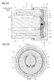
- FIG. 3 is a (lateral) cross-sectional view viewed in the A-A direction indicated in FIG. 2 .
- the cap 17 and the electromagnetic solenoid 14 having an annular shape are arranged concentrically with the valve seat 11 having a cylindrical post shape.
- the first communicating channel 12 and the second communicating channel 13 each have a sectorial cross-sectional shape, and are arranged along the inner side of the annular electromagnetic solenoid 14.
- the first communicating channel 12 is arranged closer to the electromagnetic solenoid 14 than the second communicating channel 13, so that a greater electromagnetic force is generated in the vicinity of the first communicating channel 12 than in the vicinity of the second communicating channel 13.
- the cross-sectional area of the first communicating channel 12 (the aperture area of the opening 12a in the first communicating channel 12) is equalized with the cross-sectional area of the second communicating channel 13 (the aperture area of the opening 13a in the second communicating channel 13).
- the cross-sectional areas of the first and second communicating channels 12 and 13 need not be equal.
- the cross-sectional area of the second communicating channel 13 (the aperture area of the opening 13a in the second communicating channel 13) may be greater than the cross-sectional area of the first communicating channel 12 (the aperture area of the opening 12a in the first communicating channel 12).
- FIG. 4 is a (lateral) cross-sectional view of the B-B cross section indicated in FIG. 2 .
- the valve element 1 has the first through holes 15c, arranged at the position spaced from and close to the open/close portion 15a, which opens and closes the opening 12a of the first communicating channel 12.
- the second through holes 15d are arranged so as to overlap portions of the opening 13a of the second communicating channel 13.
- the aperture area of the second through holes 15d is smaller than the aperture area of the opening 13a of the second communicating channel 13.
- the support portion 15b supports the open/close portion 15a at a portion of the outer peripheral portion of the valve element 15 (the step portion 17a, the valve seat 11 (see FIG.
- the valve element 15 can be opened or closed on the valve seat 11 by the electromagnetic solenoid 14, so that open/close control of the opening 12a of the first communicating channel 12 can be performed. Therefore, when the flow rate is high in the damper 1 with variable damping force, the damping force can be reduced (since the piston rod 3a can be easily displaced with respect to the cylinder 2).
- FIG. 5A is a longitudinal cross-sectional view of the damping-force control device 9 in the state in which the valve element 15 is open
- FIG. 5B is a lateral cross-sectional view of the damping-force control device 9 in the state in which the valve element 15 is open.
- a flow channel F1 extending from the opening (liquid outlet) 12a of the first communicating channel 12 through the first through holes 15c and the side of the valve element 15 opposite to the valve seat 11 can be formed in the variable pressure chamber 16.
- the flow channel F1 further passes through the second through holes 15d and reaches the opening (liquid inlet) 13a of the second communicating channel 13.
- the portion of the valve element 15 in the vicinity of the second through holes 15d is closer to the valve seat 11 than the portion of the valve element 15 in the vicinity of the first through holes 15c in the state in which the valve element 15 is open.
- the aperture area of the second through holes 15d is smaller than the aperture area of the first through holes 15c. Therefore, when the operating oil 5 (illustrated in FIG. 1 ) flows from the variable pressure chamber 16 to the second communicating channel 13, the damping force is generated by the second through holes 15d, which is close to the valve seat 11 (the opening 13a of the second communicating channel 13).
- the pressure of the operating oil 5 is approximately equally applied to the valve seat 11 side (front side) of the valve element 15 and the opposite side (back side) of the valve element 15. Therefore, the valve element 15 is prevented from coming apart from the electromagnetic solenoid 14 and the valve seat 11, so that the electromagnetic solenoid 14 can attract and close the valve element 15 even with a small electromagnetic force. Since it is sufficient for the electromagnetic solenoid 14 to generate a small electromagnetic force, the power consumption can be reduced. Further, a flow channel F2 extending from the opening 12a through the valve seat 11 side of the valve element 15 to the opening 13a is also formed.
- the damping-force control device 9 can be basically formed of the valve seat 11, the electromagnetic solenoid 14, the valve element 15, and the cap 17, the damping-force control device 9 has a simple structure, the number of parts is small, and the manufacturing cost can be lowered.
- FIG. 6 is a longitudinal cross-sectional view of the damping-force control device 9 which is arranged in the damper with variable damping force according to the second embodiment of the present invention.
- the second embodiment is different from the first embodiment in that a groove 13b is arranged at the opening (liquid inlet) 13a of the second communicating channel 13.
- the groove 13b is formed on the opening 12a side of the opening 13a.
- the provision of the groove 13b has an effect of broadening a portion of the flow channel F2 illustrated in FIG. 5A , so that the flow rate of the operating oil 5 through the flow channel F2 can be increased. Thus, it is possible to reduce the damping force when the valve is open.
- FIG. 7 is a longitudinal cross-sectional view of the damping-force control device 9 which is arranged in the damper with variable damping force according to the third embodiment of the present invention.
- the third embodiment is different from the first embodiment in that a bevel portion 13c is arranged at the opening (liquid inlet) 13a of the second communicating channel 13.
- the bevel portion 13c is formed on the opening 12a side of the opening 13a.
- the provision of the bevel portion 13c has an effect of broadening a portion of the flow channel F2 illustrated in FIG. 5A , so that the flow rate of the operating oil 5 through the flow channel F2 can be increased. Thus, it is possible to reduce the damping force when the valve is open.
- FIG. 8 is a longitudinal cross-sectional view of the damping-force control device 9 which is arranged in the damper with variable damping force according to the fourth embodiment of the present invention.
- the fourth embodiment is different from the first embodiment in that a bypass channel 13d is arranged at the opening (liquid inlet) 13a of the second communicating channel 13.
- the bypass channel 13d is formed on the opening 12a side of the opening 13a. Since the part of the flow through the flow channel F2 branches into the 13d, the provision of the bypass channel 13d has an effect of substantially broadening the flow channel F2 illustrated in FIG. 5A , so that the flow rate of the operating oil 5 through the flow channel F2 can be increased. Thus, it is possible to reduce the damping force when the valve is open.
- FIG. 9 is a longitudinal cross-sectional view of the damping-force control device 9 which is arranged in the damper with variable damping force according to the fifth embodiment of the present invention.
- the fifth embodiment is different from the first embodiment in that the electromagnetic solenoid 14 is sealed up in the valve seat 11 with a sealant 19. Since the electromagnetic solenoid 14 does not come into contact with the operating oil 5, the electromagnetic solenoid 14 can be insulated from the operating oil 5 with high reliability.
- the sealant 19 is preferably a nonmagnetic material. In this case, when the valve is closed, the magnetic path generated in the valve seat 11 can be lead to the valve element 15, so that the attractive force can be kept strong.
- FIG. 10 is a longitudinal cross-sectional view of the damping-force control device 9 which is arranged in the damper with variable damping force according to the sixth embodiment of the present invention.
- the sixth embodiment is different from the fifth embodiment in that a bolt 21 as a means for fastening the cap 17 is arranged approximately on the center axis of the valve seat 11.
- a female thread into which the bolt 21 is screwed is formed approximately on the center axis of the valve seat 11.
- a through-hole through which the bolt 21 passes is arranged at the center of the valve element 15.
- the side wall of the through-hole is so apart from the bolt 21 that the bolt 21 does not come into contact with the side wall of the through-hole even when the valve element 15 is opened or closed.
- a through-hole through which the bolt 21 passes is also arranged at the center of the cap 17.
- An oil packing 22 is arranged between the bolt 21 and the cap 17.
- FIG. 11 is a longitudinal cross-sectional view of the damping-force control device 9 which is arranged in the damper with variable damping force according to the seventh embodiment of the present invention.
- the seventh embodiment is different from the sixth embodiment in that the cap 17 is constituted by a main portion and a separate stopper (opening limiter) 17b, which is formed separately from the main portion of the cap 17.
- the separate stopper (opening limiter) 17b includes a planar main portion and a step portion 17a.
- the outer periphery portion of the valve element 15 is held between the step portion 17a and the valve seat 11.
- the opening of the valve element 15 contained in the variable pressure chamber 16 can be limited when the valve element 15 comes into contact with the planar main portion of the separate stopper (opening limiter) 17b.
- the maximum degree of opening of the valve element 15 can be easily changed and adjusted by changing the thickness of the planar main portion of the separate stopper (opening limiter) 17b and the height of the step portion 17a, i.e., by replacing the separate stopper (opening limiter) 17b with another separate stopper which has a different thickness of the planar main portion or a different height of the step portion 17a.
- the main portion and the separate stopper (opening limiter) 17b may be made of different materials.
- the separate stopper (opening limiter) 17b may be made of a material which is more resistant to the operating oil 5 than the main portion of the cap 17, and the main portion of the cap 17 may be made of a material which has higher strength than the separate stopper (opening limiter) 17b.
- FIG. 12 is a lateral cross-sectional view of the damping-force control device 9 which is arranged in the damper with variable damping force according to the eighth embodiment of the present invention.
- the eighth embodiment is different from the first embodiment in that an orifice 15e is arranged in the valve element 15.
- the orifice 15e is arranged at a position in the valve element 15 in contact or proximity with the first communicating channel 12. According to the above provision, the damping force can be adjusted in such a manner that the rise (rising rate) of the damping force in the valve-closed state becomes gentle.
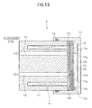
- FIG. 13 is a longitudinal cross-sectional view of the damping-force control device 9 which is arranged in the damper with variable damping force according to the ninth embodiment of the present invention.
- the ninth embodiment is different from the first embodiment in that a shim (spacer) 15f is inserted between the valve seat 11 and the valve element 15. Since the shim 15f is inserted between the valve seat 11 and the valve element 15, it is possible to prevent the valve element 15 from coming into contact with the valve seat 11 when the electromagnetic solenoid 14 exerts no attractive force even in the valve-closed state.
- a gap is produced on the valve seat 11 side of the valve element 15 in the range from the opening 12a of the first communicating channel 12 to the opening 13a of the second communicating channel 13, so that an intermediate channel 23 through which the first communicating channel 12 communicates with the second communicating channel 13 without passing through the valve element 15 can be formed. Therefore, it is possible to prevent rapid rising of the damping force and occurrence of abnormal noise. Since a differential pressure corresponding to the flow rate of the operating oil is generated, the force of driving the valve element 15 can be suppressed even when a rapid stroke or the like occurs.
- the cap 17 is coupled to the outer periphery of the valve seat 11 by fitting, press fitting, or the like and held on the outer periphery of the valve seat 11.
- the cap 17 and the seat face of the valve seat 11 are formed to be so close to each other that compressive force is exerted on the valve element 15 and the shim 15f.
Landscapes
- Engineering & Computer Science (AREA)
- General Engineering & Computer Science (AREA)
- Mechanical Engineering (AREA)
- Fluid-Damping Devices (AREA)
- Magnetically Actuated Valves (AREA)
Abstract

Description
- The present invention relates to a damper with variable damping force, the damping force of which can be variably controlled.
- In a damper with variable damping force which has been proposed (for example, in Patent document 1), a valve element which is arranged in a flow channel between a reservoir and a cylinder containing a piston is opened or closed by an electromagnetic solenoid actuator so as to change the damping force of the damper. In addition, in another damper with variable damping force which has been proposed (for example, in Patent document 2), a valve element which is arranged in a flow channel formed in a piston contained in a cylinder is opened or closed by electromagnetic attractive force generated by an electromagnetic solenoid so as to change the damping force of the damper.
-
- Patent document 1: Japanese Patent Laid-Open No.
H09-236147 - Patent document 2: Japanese Patent Laid-Open No.
2008-275126 - However, since the valve element in the damper with variable damping force disclosed in Patent document 1 is opened or closed by the electromagnetic solenoid actuator, the construction of the damper with variable damping force disclosed in Patent document 1 is complicated, and the number of the constituent parts of the damper with variable damping force disclosed in Patent document 1 becomes large. Therefore, the manufacturing cost of the damper with variable damping force disclosed in Patent document 1 becomes high.
- On the other hand, in the damper with variable damping force disclosed in
Patent document 2, the valve element is directly brought into contact by the electromagnetic solenoid, the construction of the damper with variable damping force disclosed inPatent document 2 is simple, and the number of the constituent parts of the damper with variable damping force disclosed inPatent document 2 is small. Therefore, the manufacturing cost of the damper with variable damping force disclosed inPatent document 2 can be lowered. However, the electromagnetic force (attractive force) generated by the electromagnetic solenoid is inversely proportional to the square of the distance. Therefore, when the valve opens and the valve element comes apart from the electromagnetic solenoid by a certain distance, the effect of the electromagnetic force generated by the electromagnetic solenoid rapidly attenuates, so that there is a possibility that great power consumption is needed for generation of electromagnetic force which is necessary for attracting the valve element and closing the valve. - In view of above, the object of the present invention is to provide a damper with variable damping force which has a simple structure and can suppress the power consumption.
- An aspect of the present invention provides a damper with variable damping force comprising:
- an inner cylinder which defines an inner chamber therein, where a piston is in slidable contact with the inner chamber;
- an outer cylinder which is arranged outside the inner cylinder and defines a reservoir chamber between the inner cylinder and the outer cylinder; and
- a damping-force control device which controls a damping force by controlling a flow rate of an operating oil between the inner chamber and the reservoir chamber;
- wherein
- the damping-force control device includes,
- a valve seat which is formed to externally project from the outer cylinder, and in which an opening for a first communicating channel connected to the inner chamber and an opening for a second communicating channel connected to the reservoir chamber are formed,
- a valve element which opens and closes on the valve seat by electromagnetic force, and controls a flow of the operating oil between the first communicating channel and the second communicating channel, and
- a cap which defines a variable pressure chamber between the valve seat and the valve element, and integrally holds the valve element and the valve seat, where the variable pressure chamber can be connected to the first communicating channel and the second communicating channel.
- According to the present invention, the damper with variable damping force includes the inner and outer cylinders, the piston, the reservoir chamber, and the damping-force control device which includes the valve seat, the valve element, and the cap. Therefore, the damping-force control device and the damper with variable damping force can be constructed to have a simple structure. In addition, since the number of parts can be reduced, the manufacturing cost is lowered.
- In addition, in the state in which the valve element is opened, the valve element comes into contact with the cap when the extent of opening of the valve element increases. Therefore, the increase in the extent of opening can be suppressed, and the electromagnetic solenoid can attract the valve element and close the valve even when the electromagnetic force is small. Consequently, the power consumption can be reduced.
- In addition, preferably the first communicating channel communicates the second communicating channel through an opening of the valve element in a state in which the valve element is open, and an biasing force which impels the valve element to a direction of closing the valve element is exerted on the valve element by a differential pressure generated between a front side and a back side of the valve element when the operating oil flows.
- In the case where the damper with variable damping force has the above feature, the flow channel from the first communication channel to the second communication channel in the variable pressure chamber is formed to pass the side of the valve element opposite to the valve seat, and the operating oil flowing through the flow channel applies to the valve element a pressure in a direction of closing the valve. Therefore, it is possible to prevent the valve element from coming apart from the electromagnetic solenoid, and thus close the valve with a small electromagnetic force. Consequently, the power consumption can be reduced.
- In addition, preferably, the valve element comprises,
- a first through hole arranged in a vicinity of an open and close portion which opens and closes the opening for the first communicating channel,
- a support portion which supports the open and close portion in a part of an outer peripheral portion of the valve seat in such a manner that the open and close portion can be freely opened and closed, and
- a second through hole arranged to overlap a part of the opening for the second communicating channel. Preferably, the first through hole is more apart from the support portion than the second through hole.
- In the case where the damper with variable damping force has the above feature, a flow channel of a flow from the opening for the first communicating channel through the first hole and the side of the valve element opposite to the valve seat can be formed in the variable pressure chamber. This flow channel further passes through the second hole and reaches the opening for the second communicating channel. Since the first hole is more apart from the support portion than the second hole, the portion of the valve element in the vicinity of the second hole is more close to the valve seat than the portion of the valve element in the vicinity of the first hole. Therefore, when the operating oil flows from the variable pressure chamber to the second communicating channel, the damping force is generated by the second hole, which is close to the valve seat (the opening for the second communicating channel). At this time, the inner pressure on the side of the valve element opposite to the valve seat in the variable pressure chamber becomes higher than the inner pressure in the second communicating channel (on the valve seat side of the valve element in the variable pressure chamber), so that a force in the direction of closing the valve is generated.
- In addition, preferably, the damper with variable damping force, further comprises a spacer arranged between the valve element and the valve seat to provide an intermediate channel through which the first communicating channel communicates with the second communicating channel without passing through the valve element.
- In the case where the damper with variable damping force has the above feature, even when a rapid stroke or the like occurs, it is possible to suppress the driving force of the valve element and prevent a rapid rise of the damping force.
- According to the present invention, there is provided a damper with variable damping force which has a simple structure and can suppress the power consumption.
-
-
FIG. 1 is a longitudinal cross-sectional view of a damper with variable damping force according to a first embodiment of the present invention. -
FIG. 2 is a longitudinal cross-sectional view of a damping-force control device arranged in the damper with variable damping force according to the first embodiment of the present invention. -
FIG. 3 is a (lateral) cross-sectional view viewed in an A-A direction indicated inFIG. 2 . -
FIG. 4 is a (lateral) cross-sectional view viewed in a B-B direction indicated inFIG. 2 . -
FIGS. 5A and 5B are a longitudinal cross-sectional view and a lateral cross-sectional view of the damping-force control device in the state in which a valve element is open, and indicate flow channels from a first communicating channel to a second communicating channel in a variable pressure chamber. -
FIG. 6 is a longitudinal cross-sectional view of a damping-force control device which is arranged in a damper with variable damping force according to a second embodiment of the present invention. -
FIG. 7 is a longitudinal cross-sectional view of a damping-force control device which is arranged in a damper with variable damping force according to a third embodiment of the present invention. -
FIG. 8 is a longitudinal cross-sectional view of a damping-force control device which is arranged in a damper with variable damping force according to a fourth embodiment of the present invention. -
FIG. 9 is a longitudinal cross-sectional view of a damping-force control device which is arranged in a damper with variable damping force according to a fifth embodiment of the present invention. -
FIG. 10 is a longitudinal cross-sectional view of a damping-force control device which is arranged in a damper with variable damping force according to a sixth embodiment of the present invention. -
FIG. 11 is a longitudinal cross-sectional view of a damping-force control device which is arranged in a damper with variable damping force according to a seventh embodiment of the present invention. -
FIG. 12 is a lateral cross-sectional view of a damping-force control device which is arranged in a damper with variable damping force according to an eighth embodiment of the present invention. -
FIG. 13 is a longitudinal cross-sectional view of a damping-force control device which is arranged in a damper with variable damping force according to a ninth embodiment of the present invention. - Hereinbelow, the embodiments of the present invention are explained in detail below with reference to drawings when necessary. In the drawings, identical or equivalent components or constituents are indicated by the same reference numbers, and identical explanations are not repeated.
-
FIG. 1 is a longitudinal cross-sectional view of a damper 1 with variable damping force according to a first embodiment of the present invention. In the damper 1 with variable damping force, apiston 3 is slidably fitted into acylinder 2, i.e., thepiston 3 is in slidable contact with thecylinder 2, where thecylinder 2 is filled with an operatingoil 5. An upper chamber (inner chamber) 2a is defined by thecylinder 2 and thepiston 3, and an end of apiston rod 3a is connected to thepiston 3. Thepiston rod 3a extends across theupper chamber 2a and passes through an upper end portion of thecylinder 2 and abuffer member 2d. Thepiston rod 3a is slidably fitted into the upper end portion of thecylinder 2 and thebuffer member 2d without leakage of the operatingoil 5 outside. Abottom valve 4 is arranged below thepiston 3 in thecylinder 2. Acheck valve 4a is arranged in thebottom valve 4. Thecheck valve 4a allows the operatingoil 5 to flow from areservoir chamber 7 through a throughhole 2f and alower chamber 2c to amiddle chamber 2b, and does not allow the operatingoil 5 to flow from themiddle chamber 2b to thereservoir chamber 7. Alternatively, the bottom valve 4 (thecheck valve 4a) may be arranged at the throughhole 2f. In this case, no partition exists between thelower chamber 2c and themiddle chamber 2b, so that one of thelower chamber 2c and themiddle chamber 2b can be omitted. In addition, acheck valve 3b is arranged in thepiston 3. Thecheck valve 3b allows the operatingoil 5 to flow from themiddle chamber 2b to the upper chamber (inner chamber) 2a, and does not allow the operatingoil 5 to flow from the upper chamber (inner chamber) 2a to themiddle chamber 2b. - An
outer cylinder 8 is arranged outside thecylinder 2. Thereservoir chamber 7 is defined by thecylinder 2 and theouter cylinder 8. Thereservoir chamber 7 is filled with the operatingoil 5 and a gas. Thereservoir chamber 7 is connected to themiddle chamber 2b through thebottom valve 4, which is arranged in the lower portion of thecylinder 2. - Further, a through
hole 2e is arranged in the upper portion of thecylinder 2. The upper chamber (inner chamber) 2a is connected to an upper portion of anintermediate oil channel 6 through the throughhole 2e. Theintermediate oil channel 6 is arranged outside thecylinder 2 inside theouter cylinder 8 and defined by a portion of the side wall of thecylinder 2. Theintermediate oil channel 6 is arranged along the axis direction of thecylinder 2, and the lower portion of theintermediate oil channel 6 is connected to a damping-force control device 9. The damping-force control device 9 is arranged outside the lower portion of theouter cylinder 8, and connected to the lower portion of thereservoir chamber 7 in the lower portion of theouter cylinder 8. - In the above structure of the damper with variable damping force, the upper chamber (inner chamber) 2a is connected through the through
hole 2e, theintermediate oil channel 6, and the damping-force control device 9 to the lower portion of thereservoir chamber 7 in this order, and is further connected through the throughhole 2f and thebottom valve 4 to themiddle chamber 2b. The upper portion of theintermediate oil channel 6 is connected to the upper chamber (inner chamber) 2a, and the lower portion of theintermediate oil channel 6 is connected to the damping-force control device 9. The damping-force control device 9 is connected to the upper chamber (inner chamber) 2a through theintermediate oil channel 6, and to thereservoir chamber 7. The damping-force control device 9 controls the damping force generated by the damper 1 with variable damping force, by controlling the flow rate of the operatingoil 5 through theintermediate oil channel 6, i.e., by controlling the flow rate of the operatingoil 5 flowing from theintermediate oil channel 6 into the damping-force control device 9. - When the
piston rod 3a is drawn out of thecylinder 2 in the damper 1 with variable damping force, thepiston 3 is raised with thepiston rod 3a, and the volume of the upper chamber (inner chamber) 2a is reduced. The operatingoil 5 in the upper chamber (inner chamber) 2a flows through the throughhole 2e and theintermediate oil channel 6 to the damping-force control device 9. Further, the operatingoil 5 flows out of the damping-force control device 9 to thereservoir chamber 7, so that the liquid level of the operatingoil 5 in thereservoir chamber 7 is raised, and the gas above the liquid level is compressed. Furthermore, the operatingoil 5 flows out of thereservoir chamber 7 through the bottom valve 4 (thecheck valve 4a) to themiddle chamber 2b. - On the other hand, when the
piston rod 3a is pushed into thecylinder 2 in the damper 1 with variable damping force, an amount of the operatingoil 5 corresponding to the extent of entry of thepiston rod 3a flows out of the upper chamber (inner chamber) 2a through the throughhole 2e and theintermediate oil channel 6 to the damping-force control device 9. - As explained above, either when the
piston rod 3a is drawn out of thecylinder 2 or when thepiston rod 3a is pushed into thecylinder 2, the operatingoil 5 flows out of the upper chamber (inner chamber) 2a through theintermediate oil channel 6 to the damping-force control device 9, and further flows from the damping-force control device 9 to thereservoir chamber 7. In other words, both when thepiston rod 3a is drawn out of thecylinder 2 and when thepiston rod 3a is pushed into thecylinder 2, the operatingoil 5 in the damping-force control device 9 always unidirectionally flows in a direction from theintermediate oil channel 6 into the damping-force control device 9 and from the damping-force control device 9 to thereservoir chamber 7. -
FIG. 2 is a longitudinal cross-sectional view of the damping-force control device 9 arranged in the damper with variable damping force according to the first embodiment of the present invention. The damping-force control device 9 includes avalve seat 11 having a cylindrical post shape. Anelectromagnetic solenoid 14 is embedded in thevalve seat 11 along the circular periphery of the cylindrical post shape of thevalve seat 11. It is preferable that a soft magnetic material exhibiting a low hysteresis (having a small coercive force) and having a great magnetic permeability, such as soft iron, be used in thevalve seat 11. A first communicatingchannel 12 and a second communicatingchannel 13 are formed in thevalve seat 11. The first communicatingchannel 12 and the second communicatingchannel 13 are arranged apart from each other, and each penetrate thevalve seat 11. The first communicatingchannel 12 is connected, on theouter cylinder 8 side, to the intermediate oil channel 6 (as illustrated inFIG. 1 ) and further to the upper chamber (inner chamber) 2a (as illustrated inFIG. 1 ), so that the operatingoil 5 flows from theouter cylinder 8 side into the damping-force control device 9. The second communicatingchannel 13 is connected, on theouter cylinder 8 side, to the reservoir chamber 7 (as illustrated inFIG. 1 ), so that the operatingoil 5 flows out of the damping-force control device 9 to theouter cylinder 8 side (i.e., to the reservoir chamber 7). - The side of the
valve seat 11 opposite to theouter cylinder 8 is approximately flat, and avalve element 15 having an approximately flat shape is arranged on the side of thevalve seat 11 opposite to theouter cylinder 8. An opening (liquid outlet) 12a of the first communicatingchannel 12 and an opening (liquid inlet) 13a of the second communicatingchannel 13 are arranged on the approximately flat surface of thevalve seat 11 located opposite to theouter cylinder 8. The outer peripheral portion of thevalve element 15 is held between astep portion 17a of acap 17 and thevalve seat 11. It is preferable that a soft magnetic material exhibiting a low hysteresis (having a small coercive force) and having a great magnetic permeability, such as soft iron, be used in thevalve element 15 as in thevalve seat 11. In the example illustrated inFIG. 2 , thevalve element 15 is formed by laminating four plates. Alternatively, the number of plate(s) constituting thevalve element 15 may be other than four. Avariable pressure chamber 16 is arranged on the side of thevalve element 15 opposite to thevalve seat 11. Thevariable pressure chamber 16 is defined by thecap 17 and the valve element 15 (or the valve seat 11). In particular, when thevariable pressure chamber 16 is regarded to be defined by thecap 17 and thevalve seat 11, thevalve element 15 can be regarded to be contained in thevariable pressure chamber 16, and thevariable pressure chamber 16 can be regarded to be connected to the first communicatingchannel 12 and the second communicatingchannel 13. Thecap 17 limits the maximum opening of thevalve element 15. When the opening of thevalve element 15 increases, a portion of thevalve element 15 comes more apart from thevalve seat 11, and approaches thecap 17. When the opening of thevalve element 15 further increases, the portion of thevalve element 15 comes into contact with thecap 17, and the opening of thevalve element 15 does not further increase. An oil packing 18 is arranged between the side surface of thevalve seat 11 and thecap 17, and thevariable pressure chamber 16 is sealed up by thecap 17 in such a manner that the operatingoil 5 in thevariable pressure chamber 16 does not externally leak even when the operatingoil 5 in thevariable pressure chamber 16 is pressurized. It is preferable that a nonmagnetic material such as resin or aluminum be used in thecap 17 for preventing exertion of an attractive force on thevalve element 15. Thecap 17 is coupled to the outer periphery of thevalve seat 11 by fitting, press fitting, or the like and held on the outer periphery of thevalve seat 11. In order that thestep portion 17a in thecap 17 can exert sufficient holding force on the outer peripheral portion of thevalve element 15, thecap 17 and the seat face of thevalve seat 11 are formed to be so close to each other that compressive force is exerted on thevalve element 15. -
FIG. 2 illustrates a state in which thevalve element 15 is closed. Current flows in theelectromagnetic solenoid 14 and electromagnetic force (attractive force) generated by theelectromagnetic solenoid 14 and thevalve seat 11 is exerted on thevalve element 15, so that thevalve element 15 is attracted by theelectromagnetic solenoid 14 and thevalve seat 11 and attracted with contact with thevalve seat 11. Therefore, the opening (liquid outlet) 12a of the first communicatingchannel 12 is closed by an open/close portion 15a in thevalve element 15, i.e., the opening (liquid outlet) 12a is closed. In addition, first throughholes 15c penetrating thevalve element 15 are arranged at positions spaced from and close to the open/close portion 15a (in a vicinity of the opening (liquid outlet) 12a). The opening (liquid inlet) 13a of the second communicatingchannel 13 communicates with thevariable pressure chamber 16 through second throughholes 15d arranged in thevalve element 15 even in the state in which thevalve element 15 is brought into contact with thevalve seat 11. The open/close portion 15a, the first throughholes 15c, and the second throughholes 15d, which are arranged in thevalve element 15, are supported by asupport portion 15b in thevalve element 15. Thesupport portion 15b is supported by the outer periphery portion of thevalve element 15. -
FIG. 3 is a (lateral) cross-sectional view viewed in the A-A direction indicated inFIG. 2 . Thecap 17 and theelectromagnetic solenoid 14 having an annular shape are arranged concentrically with thevalve seat 11 having a cylindrical post shape. The first communicatingchannel 12 and the second communicatingchannel 13 each have a sectorial cross-sectional shape, and are arranged along the inner side of the annularelectromagnetic solenoid 14. The first communicatingchannel 12 is arranged closer to theelectromagnetic solenoid 14 than the second communicatingchannel 13, so that a greater electromagnetic force is generated in the vicinity of the first communicatingchannel 12 than in the vicinity of the second communicatingchannel 13. - In the example of
FIG. 3 , the cross-sectional area of the first communicating channel 12 (the aperture area of theopening 12a in the first communicating channel 12) is equalized with the cross-sectional area of the second communicating channel 13 (the aperture area of theopening 13a in the second communicating channel 13). However, the cross-sectional areas of the first and second communicatingchannels opening 13a in the second communicating channel 13) may be greater than the cross-sectional area of the first communicating channel 12 (the aperture area of theopening 12a in the first communicating channel 12). In this case, when the flow rate is high, increase in the conduit resistance of the second communicatingchannel 13 can be suppressed, and therefore the damping force can be reduced (since thepiston rod 3a can be easily displaced with respect to the cylinder 2). -
FIG. 4 is a (lateral) cross-sectional view of the B-B cross section indicated inFIG. 2 . The valve element 1 has the first throughholes 15c, arranged at the position spaced from and close to the open/close portion 15a, which opens and closes theopening 12a of the first communicatingchannel 12. In addition, the second throughholes 15d are arranged so as to overlap portions of theopening 13a of the second communicatingchannel 13. The aperture area of the second throughholes 15d is smaller than the aperture area of theopening 13a of the second communicatingchannel 13. Thesupport portion 15b supports the open/close portion 15a at a portion of the outer peripheral portion of the valve element 15 (thestep portion 17a, the valve seat 11 (seeFIG. 2 )) in such a manner that the open/close portion 15a can be freely opened or closed. The first throughholes 15c are more apart from thesupport portion 15b than the second throughholes 15d. Thevalve element 15 can be opened or closed on thevalve seat 11 by theelectromagnetic solenoid 14, so that open/close control of theopening 12a of the first communicatingchannel 12 can be performed. Therefore, when the flow rate is high in the damper 1 with variable damping force, the damping force can be reduced (since thepiston rod 3a can be easily displaced with respect to the cylinder 2). -
FIG. 5A is a longitudinal cross-sectional view of the damping-force control device 9 in the state in which thevalve element 15 is open, andFIG. 5B is a lateral cross-sectional view of the damping-force control device 9 in the state in which thevalve element 15 is open. In the state in which thevalve element 15 is open, a flow channel F1 extending from the opening (liquid outlet) 12a of the first communicatingchannel 12 through the first throughholes 15c and the side of thevalve element 15 opposite to thevalve seat 11 can be formed in thevariable pressure chamber 16. The flow channel F1 further passes through the second throughholes 15d and reaches the opening (liquid inlet) 13a of the second communicatingchannel 13. Since the second throughholes 15d are nearer to thesupport portion 15b than the first throughholes 15c, the portion of thevalve element 15 in the vicinity of the second throughholes 15d is closer to thevalve seat 11 than the portion of thevalve element 15 in the vicinity of the first throughholes 15c in the state in which thevalve element 15 is open. In addition, the aperture area of the second throughholes 15d is smaller than the aperture area of the first throughholes 15c. Therefore, when the operating oil 5 (illustrated inFIG. 1 ) flows from thevariable pressure chamber 16 to the second communicatingchannel 13, the damping force is generated by the second throughholes 15d, which is close to the valve seat 11 (theopening 13a of the second communicating channel 13). At this time, the pressure of the operatingoil 5 is approximately equally applied to thevalve seat 11 side (front side) of thevalve element 15 and the opposite side (back side) of thevalve element 15. Therefore, thevalve element 15 is prevented from coming apart from theelectromagnetic solenoid 14 and thevalve seat 11, so that theelectromagnetic solenoid 14 can attract and close thevalve element 15 even with a small electromagnetic force. Since it is sufficient for theelectromagnetic solenoid 14 to generate a small electromagnetic force, the power consumption can be reduced. Further, a flow channel F2 extending from theopening 12a through thevalve seat 11 side of thevalve element 15 to theopening 13a is also formed. - Furthermore, since the damping-
force control device 9 can be basically formed of thevalve seat 11, theelectromagnetic solenoid 14, thevalve element 15, and thecap 17, the damping-force control device 9 has a simple structure, the number of parts is small, and the manufacturing cost can be lowered. -
FIG. 6 is a longitudinal cross-sectional view of the damping-force control device 9 which is arranged in the damper with variable damping force according to the second embodiment of the present invention. The second embodiment is different from the first embodiment in that agroove 13b is arranged at the opening (liquid inlet) 13a of the second communicatingchannel 13. Thegroove 13b is formed on theopening 12a side of theopening 13a. The provision of thegroove 13b has an effect of broadening a portion of the flow channel F2 illustrated inFIG. 5A , so that the flow rate of the operatingoil 5 through the flow channel F2 can be increased. Thus, it is possible to reduce the damping force when the valve is open. -
FIG. 7 is a longitudinal cross-sectional view of the damping-force control device 9 which is arranged in the damper with variable damping force according to the third embodiment of the present invention. The third embodiment is different from the first embodiment in that abevel portion 13c is arranged at the opening (liquid inlet) 13a of the second communicatingchannel 13. Thebevel portion 13c is formed on theopening 12a side of theopening 13a. The provision of thebevel portion 13c has an effect of broadening a portion of the flow channel F2 illustrated inFIG. 5A , so that the flow rate of the operatingoil 5 through the flow channel F2 can be increased. Thus, it is possible to reduce the damping force when the valve is open. -
FIG. 8 is a longitudinal cross-sectional view of the damping-force control device 9 which is arranged in the damper with variable damping force according to the fourth embodiment of the present invention. The fourth embodiment is different from the first embodiment in that abypass channel 13d is arranged at the opening (liquid inlet) 13a of the second communicatingchannel 13. Thebypass channel 13d is formed on theopening 12a side of theopening 13a. Since the part of the flow through the flow channel F2 branches into the 13d, the provision of thebypass channel 13d has an effect of substantially broadening the flow channel F2 illustrated inFIG. 5A , so that the flow rate of the operatingoil 5 through the flow channel F2 can be increased. Thus, it is possible to reduce the damping force when the valve is open. -
FIG. 9 is a longitudinal cross-sectional view of the damping-force control device 9 which is arranged in the damper with variable damping force according to the fifth embodiment of the present invention. The fifth embodiment is different from the first embodiment in that theelectromagnetic solenoid 14 is sealed up in thevalve seat 11 with asealant 19. Since theelectromagnetic solenoid 14 does not come into contact with the operatingoil 5, theelectromagnetic solenoid 14 can be insulated from the operatingoil 5 with high reliability. Thesealant 19 is preferably a nonmagnetic material. In this case, when the valve is closed, the magnetic path generated in thevalve seat 11 can be lead to thevalve element 15, so that the attractive force can be kept strong. -
FIG. 10 is a longitudinal cross-sectional view of the damping-force control device 9 which is arranged in the damper with variable damping force according to the sixth embodiment of the present invention. The sixth embodiment is different from the fifth embodiment in that abolt 21 as a means for fastening thecap 17 is arranged approximately on the center axis of thevalve seat 11. A female thread into which thebolt 21 is screwed is formed approximately on the center axis of thevalve seat 11. A through-hole through which thebolt 21 passes is arranged at the center of thevalve element 15. The side wall of the through-hole is so apart from thebolt 21 that thebolt 21 does not come into contact with the side wall of the through-hole even when thevalve element 15 is opened or closed. A through-hole through which thebolt 21 passes is also arranged at the center of thecap 17. An oil packing 22 is arranged between thebolt 21 and thecap 17. The above provision enables simple and tight fastening of thecap 17 to thevalve seat 11. In addition, thebolt 21 is preferably made of a nonmagnetic material. Since no magnetic path is formed in thebolt 21, it is possible to exert a strong attractive force on thevalve element 15. -
FIG. 11 is a longitudinal cross-sectional view of the damping-force control device 9 which is arranged in the damper with variable damping force according to the seventh embodiment of the present invention. The seventh embodiment is different from the sixth embodiment in that thecap 17 is constituted by a main portion and a separate stopper (opening limiter) 17b, which is formed separately from the main portion of thecap 17. The separate stopper (opening limiter) 17b includes a planar main portion and astep portion 17a. The outer periphery portion of thevalve element 15 is held between thestep portion 17a and thevalve seat 11. The planar main portion and thestep portion 17a of the separate stopper (opening limiter) 17b, together with thevalve seat 11, define thevariable pressure chamber 16. The opening of thevalve element 15 contained in thevariable pressure chamber 16 can be limited when thevalve element 15 comes into contact with the planar main portion of the separate stopper (opening limiter) 17b. The maximum degree of opening of thevalve element 15 can be easily changed and adjusted by changing the thickness of the planar main portion of the separate stopper (opening limiter) 17b and the height of thestep portion 17a, i.e., by replacing the separate stopper (opening limiter) 17b with another separate stopper which has a different thickness of the planar main portion or a different height of thestep portion 17a. Further, the main portion and the separate stopper (opening limiter) 17b may be made of different materials. For example, the separate stopper (opening limiter) 17b may be made of a material which is more resistant to the operatingoil 5 than the main portion of thecap 17, and the main portion of thecap 17 may be made of a material which has higher strength than the separate stopper (opening limiter) 17b. -
FIG. 12 is a lateral cross-sectional view of the damping-force control device 9 which is arranged in the damper with variable damping force according to the eighth embodiment of the present invention. The eighth embodiment is different from the first embodiment in that anorifice 15e is arranged in thevalve element 15. Theorifice 15e is arranged at a position in thevalve element 15 in contact or proximity with the first communicatingchannel 12. According to the above provision, the damping force can be adjusted in such a manner that the rise (rising rate) of the damping force in the valve-closed state becomes gentle. -
FIG. 13 is a longitudinal cross-sectional view of the damping-force control device 9 which is arranged in the damper with variable damping force according to the ninth embodiment of the present invention. The ninth embodiment is different from the first embodiment in that a shim (spacer) 15f is inserted between thevalve seat 11 and thevalve element 15. Since theshim 15f is inserted between thevalve seat 11 and thevalve element 15, it is possible to prevent thevalve element 15 from coming into contact with thevalve seat 11 when theelectromagnetic solenoid 14 exerts no attractive force even in the valve-closed state. According to the above provision, a gap is produced on thevalve seat 11 side of thevalve element 15 in the range from theopening 12a of the first communicatingchannel 12 to theopening 13a of the second communicatingchannel 13, so that anintermediate channel 23 through which the first communicatingchannel 12 communicates with the second communicatingchannel 13 without passing through thevalve element 15 can be formed. Therefore, it is possible to prevent rapid rising of the damping force and occurrence of abnormal noise. Since a differential pressure corresponding to the flow rate of the operating oil is generated, the force of driving thevalve element 15 can be suppressed even when a rapid stroke or the like occurs. Thecap 17 is coupled to the outer periphery of thevalve seat 11 by fitting, press fitting, or the like and held on the outer periphery of thevalve seat 11. In order that thestep portion 17a of thecap 17 can exert sufficient holding force on the outer peripheral portion of thevalve element 15 and theshim 15f, thecap 17 and the seat face of thevalve seat 11 are formed to be so close to each other that compressive force is exerted on thevalve element 15 and theshim 15f. -
- 1:
- Damper with variable damping force
- 2:
- Cylinder
- 2a:
- Upper Chamber (Inner Chamber)
- 2b:
- Middle Chamber
- 2c:
- Lower Chamber
- 2d:
- Buffer Member
- 3:
- Piston
- 3a:
- Piston Rod
- 3b:
- Check Valve
- 4:
- Bottom Valve
- 4a:
- Check Valve
- 5:
- Operating Oil
- 6:
- Intermediate Oil Channel
- 7:
- Reservoir Chamber
- 8:
- Outer Cylinder
- 9:
- Damping-force Control Device
- 11:
- Valve seat
- 12:
- First Communicating Channel
- 12a:
- Opening (Liquid Outlet)
- 13:
- Second Communicating Channel
- 13a:
- Opening
- 13b:
- Groove
- 13c:
- Bevel Portion
- 13d:
- Bypass Channel
- 14:
- Electromagnetic Solenoid
- 15:
- Valve Element
- 15a:
- Open/Close Portion
- 15b:
- Support Portion
- 15c:
- First Holes
- 15d:
- Second Holes
- 15e:
- Orifice
- 15f:
- Shim
- 16:
- Variable Pressure Chamber
- 17:
- Cap
- 17a:
- Step Portion
- 17b:
- Separate Stopper (Opening Limiter)
- 18:
- Oil Packing
- 19:
- Sealant
- 21:
- Bolt
- 22:
- Oil Packing
- F1, F2:
- Channel from First Communicating Channel to Second Communicating Channel in Variable Pressure Chamber
- P:
- Pressure Directed to Close Valve Element
Claims (4)
- A damper with variable damping force comprising:an inner cylinder which defines an inner chamber therein, where a piston is in slidable contact with the inner chamber;an outer cylinder which is arranged outside the inner cylinder and defines a reservoir chamber between the inner cylinder and the outer cylinder; anda damping-force control device which controls a damping force by controlling a flow rate of an operating oil between the inner chamber and the reservoir chamber;whereinthe damping-force control device includes,a valve seat which is formed to externally project from the outer cylinder, and in which an opening for a first communicating channel connected to the inner chamber and an opening for a second communicating channel connected to the reservoir chamber are formed,a valve element which opens and closes on the valve seat by electromagnetic force, and controls a flow of the operating oil between the first communicating channel and the second communicating channel, anda cap which defines a variable pressure chamber between the valve seat and the valve element, and integrally holds the valve element and the valve seat, where the variable pressure chamber can be connected to the first communicating channel and the second communicating channel.
- The damper with variable damping force according to claim 1, wherein the first communicating channel communicates the second communicating channel through an opening of the valve element in a state in which the valve element is open, and an biasing force which impels the valve element to a direction of closing the valve element is exerted on the valve element by a differential pressure generated between a front side and a back side of the valve element when the operating oil flows.
- The damper with variable damping force according to claim 1, wherein: the valve element comprises,a first through hole arranged in a vicinity of an open and close portion which opens and closes the opening for the first communicating channel,a support portion which supports the open and close portion in a part of an outer peripheral portion of the valve seat in such a manner that the open and close portion can be freely opened and closed, anda second through hole arranged to overlap a part of the opening for the second communicating channel; andwherein the first through hole is more apart from the support portion than the second through hole.
- The damper with variable damping force according to claim 1, further comprising a spacer arranged between the valve element and the valve seat to provide an intermediate channel through which the first communicating channel communicates with the second communicating channel without passing through the valve element.
Applications Claiming Priority (2)
| Application Number | Priority Date | Filing Date | Title |
|---|---|---|---|
| JP2011044571 | 2011-03-02 | ||
| PCT/JP2012/055481 WO2012118211A1 (en) | 2011-03-02 | 2012-03-02 | Damper with variable damping force |
Publications (2)
| Publication Number | Publication Date |
|---|---|
| EP2682639A1 true EP2682639A1 (en) | 2014-01-08 |
| EP2682639A4 EP2682639A4 (en) | 2016-07-27 |
Family
ID=46758135
Family Applications (1)
| Application Number | Title | Priority Date | Filing Date |
|---|---|---|---|
| EP12752888.3A Withdrawn EP2682639A4 (en) | 2011-03-02 | 2012-03-02 | Damper with variable damping force |
Country Status (5)
| Country | Link |
|---|---|
| US (1) | US9303711B2 (en) |
| EP (1) | EP2682639A4 (en) |
| JP (1) | JP5732126B2 (en) |
| CN (1) | CN103429929B (en) |
| WO (1) | WO2012118211A1 (en) |
Families Citing this family (25)
| Publication number | Priority date | Publication date | Assignee | Title |
|---|---|---|---|---|
| US8616351B2 (en) | 2009-10-06 | 2013-12-31 | Tenneco Automotive Operating Company Inc. | Damper with digital valve |
| WO2013100076A1 (en) * | 2011-12-27 | 2013-07-04 | 日立オートモティブシステムズ株式会社 | Buffer and method for producing buffer |
| JP5619796B2 (en) * | 2012-02-15 | 2014-11-05 | 本田技研工業株式会社 | Variable damping force damper |
| US9884533B2 (en) | 2013-02-28 | 2018-02-06 | Tenneco Automotive Operating Company Inc. | Autonomous control damper |
| US9217483B2 (en) | 2013-02-28 | 2015-12-22 | Tenneco Automotive Operating Company Inc. | Valve switching controls for adjustable damper |
| WO2014134500A1 (en) | 2013-02-28 | 2014-09-04 | Tenneco Automotive Operating Company Inc. | Damper with integrated electronics |
| US9879746B2 (en) | 2013-03-15 | 2018-01-30 | Tenneco Automotive Operating Company Inc. | Rod guide system and method with multiple solenoid valve cartridges and multiple pressure regulated valve assemblies |
| US9879748B2 (en) | 2013-03-15 | 2018-01-30 | Tenneco Automotive Operating Company Inc. | Two position valve with face seal and pressure relief port |
| JP6351336B2 (en) * | 2014-03-31 | 2018-07-04 | 日立オートモティブシステムズ株式会社 | Shock absorber |
| US11007834B2 (en) | 2016-12-15 | 2021-05-18 | Tenneco Automotive Operating Company Inc. | Baffle tube for damper with electromechanical valve |
| US10054182B2 (en) | 2016-12-15 | 2018-08-21 | Tenneco Automotive Operating Company Inc. | Baffle tube for damper with electromechanical valve |
| US10479160B2 (en) | 2017-06-06 | 2019-11-19 | Tenneco Automotive Operating Company Inc. | Damper with printed circuit board carrier |
| US10588233B2 (en) | 2017-06-06 | 2020-03-10 | Tenneco Automotive Operating Company Inc. | Damper with printed circuit board carrier |
| US10987988B2 (en) * | 2017-06-28 | 2021-04-27 | Tenneco Automotive Operating Company Inc. | Damper with volume reducing insert |
| US11009093B2 (en) * | 2017-10-16 | 2021-05-18 | Suspension Direct, Inc. | Electronically adjustable shock absorber |
| US10704641B2 (en) | 2017-12-15 | 2020-07-07 | Tenneco Automotive Operating Company Inc. | Baffle for damper with electromechanical valve |
| FR3079577B1 (en) * | 2018-03-30 | 2020-03-13 | Airbus Helicopters | HYDRO ELASTIC SHOCK ABSORBER AND AIRCRAFT |
| US10837515B2 (en) | 2019-02-11 | 2020-11-17 | Tenneco Automotive Operating Company Inc. | Damper baffle tube with elastomeric skirt |
| US11091001B2 (en) * | 2019-09-23 | 2021-08-17 | DRiV Automotive Inc. | Base valve assembly for damper |
| JPWO2021117800A1 (en) * | 2019-12-12 | 2021-06-17 | ||
| JP7619839B2 (en) * | 2021-03-02 | 2025-01-22 | 本田技研工業株式会社 | Suspension system |
| SE545561C2 (en) * | 2021-11-26 | 2023-10-24 | Oehlins Racing Ab | Coil assembly for an actively controlled damping valve assembly of a vehicle |
| EP4092288A1 (en) * | 2021-05-21 | 2022-11-23 | Öhlins Racing AB | Coil assembly for an actively controlled damping valve assembly of a vehicle |
| US12305770B2 (en) | 2021-05-21 | 2025-05-20 | DRiV Automotive Inc. | Coil assembly for an actively controlled damping valve assembly of a vehicle |
| CN116749695B (en) * | 2023-07-21 | 2025-09-26 | 吉林大学 | Active energy feedback suspension system and vehicle |
Family Cites Families (27)
| Publication number | Priority date | Publication date | Assignee | Title |
|---|---|---|---|---|
| US4076276A (en) * | 1976-07-09 | 1978-02-28 | Monroe Auto Equipment Company | Base valve for independent wheel suspension strut |
| DE4104110A1 (en) * | 1991-02-11 | 1992-08-13 | Fichtel & Sachs Ag | PRE-CONTROLLED DAMPING VALVE WITH VIBRATION DAMPER-RIGHT CHARACTERISTICS |
| US5325942A (en) * | 1991-03-14 | 1994-07-05 | Monroe Auto Equipment Company | Tunable hydraulic valve for shock absorber |
| DE4314519C2 (en) * | 1993-05-03 | 1997-11-13 | Fichtel & Sachs Ag | Shut-off valve device for a vibration damper |
| ES2126055T3 (en) * | 1993-11-13 | 1999-03-16 | Delphi France Automotive Sys | SHOCK ABSORBER. |
| NL9402150A (en) * | 1994-12-19 | 1996-08-01 | Koni Bv | Continuously variable two-pipe shock absorber. |
| DE19604721A1 (en) * | 1995-02-10 | 1996-08-14 | New Joules Engineering Sales P | Shock-damper for rail-track brake |
| JP4288430B2 (en) | 1995-12-26 | 2009-07-01 | 株式会社日立製作所 | Damping force adjustable hydraulic shock absorber |
| US5924528A (en) * | 1997-02-21 | 1999-07-20 | Tenneco Automotive Inc. | Load depending damping assembly |
| JP2002364697A (en) * | 2001-06-05 | 2002-12-18 | Showa Corp | Damping force adjustable hydraulic shock absorber |
| US7562750B2 (en) * | 2004-02-10 | 2009-07-21 | Tenneco Automotive Operating Company Inc. | Air pressure proportional damper for shock absorber |
| CN100526674C (en) | 2004-05-25 | 2009-08-12 | 日产自动车株式会社 | Hydraulic shock absorber |
| JP4356016B2 (en) | 2004-07-27 | 2009-11-04 | 株式会社日立製作所 | Hydraulic shock absorber |
| SE531736C2 (en) * | 2005-06-14 | 2009-07-28 | Oehlins Racing Ab | Arrangement and device for noise canceling valve for dampers |
| KR100773362B1 (en) * | 2006-02-20 | 2007-11-05 | 주식회사 만도 | Variable damping force valve and shock absorber using the same |
| KR100842031B1 (en) | 2007-01-30 | 2008-06-27 | 주식회사 만도 | Solenoid Valve of Shock Absorber |
| DE102007020118B4 (en) * | 2007-04-28 | 2010-09-09 | Zf Friedrichshafen Ag | Self-pumping hydropneumatic strut with internal level control |
| JP4825723B2 (en) | 2007-05-07 | 2011-11-30 | 本田技研工業株式会社 | Vehicle damping force variable damper |
| US8240439B2 (en) * | 2007-05-07 | 2012-08-14 | Honda Motor Co., Ltd. | Vehicle damper of variable damping force |
| KR101568042B1 (en) | 2008-03-31 | 2015-11-10 | 가부시끼가이샤 히다치 세이사꾸쇼 | Damping force adjusting buffer |
| JP5120629B2 (en) * | 2008-03-31 | 2013-01-16 | 日立オートモティブシステムズ株式会社 | Damping force adjustable shock absorber and suspension control device using the same |
| JP5180129B2 (en) * | 2008-04-17 | 2013-04-10 | カヤバ工業株式会社 | Front fork |
| JP5106287B2 (en) * | 2008-07-17 | 2012-12-26 | カヤバ工業株式会社 | Damping valve |
| JP2010251185A (en) * | 2009-04-17 | 2010-11-04 | Toyota Motor Corp | Method for inspecting membrane electrode assembly |
| JP2011007322A (en) | 2009-05-29 | 2011-01-13 | Hitachi Automotive Systems Ltd | Damping force adjustment type shock absorber |
| KR101776323B1 (en) * | 2010-09-29 | 2017-09-07 | 히다치 오토모티브 시스템즈 가부시키가이샤 | Damper |
| JP2012163187A (en) * | 2011-02-09 | 2012-08-30 | Showa Corp | Hydraulic shock absorber and damping force generator |
-
2012
- 2012-03-02 EP EP12752888.3A patent/EP2682639A4/en not_active Withdrawn
- 2012-03-02 WO PCT/JP2012/055481 patent/WO2012118211A1/en not_active Ceased
- 2012-03-02 US US14/002,546 patent/US9303711B2/en not_active Expired - Fee Related
- 2012-03-02 CN CN201280011248.7A patent/CN103429929B/en not_active Expired - Fee Related
- 2012-03-02 JP JP2013502435A patent/JP5732126B2/en active Active
Also Published As
| Publication number | Publication date |
|---|---|
| JP5732126B2 (en) | 2015-06-10 |
| WO2012118211A1 (en) | 2012-09-07 |
| EP2682639A4 (en) | 2016-07-27 |
| CN103429929B (en) | 2014-12-31 |
| US20130341140A1 (en) | 2013-12-26 |
| JPWO2012118211A1 (en) | 2014-07-07 |
| CN103429929A (en) | 2013-12-04 |
| US9303711B2 (en) | 2016-04-05 |
Similar Documents
| Publication | Publication Date | Title |
|---|---|---|
| US9303711B2 (en) | Damper with variable damping force | |
| US20130234378A1 (en) | Suspension damper | |
| US10495177B2 (en) | Solenoid valve | |
| US7946399B2 (en) | Hydraulic shock absorber | |
| US9163693B2 (en) | Adjustable damping valve for a vibration damper | |
| US9394960B2 (en) | Hydropneumatic piston/cylinder arrangement | |
| US9810281B2 (en) | Damping force control type shock absorber | |
| EP2630389B1 (en) | Valve arrangement | |
| CN102301300A (en) | Proportional Pressure Control Valve | |
| US9022187B2 (en) | Damping valve for shock absorber | |
| DE112016004910T5 (en) | Shock absorber with adjustable damping force | |
| JP4825723B2 (en) | Vehicle damping force variable damper | |
| CN102439341A (en) | Proportional throttle valve | |
| US9395013B2 (en) | Flow control valve | |
| CN102606790B (en) | Especially for the actuator of the Electromagnetically activatable of the adjustable orifice valve of vibration damper | |
| US10400849B2 (en) | Adjustable damping valve device | |
| US20080283135A1 (en) | Electrically Controllable Valve | |
| JP2004316797A (en) | Magneto-rheological fluid damper | |
| US7669831B2 (en) | Electrically controllable valve | |
| CN118517490A (en) | Magneto-rheological shock absorber with asymmetric damping force | |
| DE4221821A1 (en) | Electromagnetically-operated valve for automobile - has magnetic armature contained in oil-filled armature space sealed by two rubber membranes | |
| EP2589807A1 (en) | Folding bellows pump | |
| CN105102851B (en) | Damping force variable shock absorber | |
| DE19739007A1 (en) | Solenoid valve for allowing or stopping flow of gas to industrial burners | |
| CN109210126A (en) | A kind of external piezoelectric ceramics variable-damp vibration damper |
Legal Events
| Date | Code | Title | Description |
|---|---|---|---|
| PUAI | Public reference made under article 153(3) epc to a published international application that has entered the european phase |
Free format text: ORIGINAL CODE: 0009012 |
|
| 17P | Request for examination filed |
Effective date: 20131001 |
|
| AK | Designated contracting states |
Kind code of ref document: A1 Designated state(s): AL AT BE BG CH CY CZ DE DK EE ES FI FR GB GR HR HU IE IS IT LI LT LU LV MC MK MT NL NO PL PT RO RS SE SI SK SM TR |
|
| DAX | Request for extension of the european patent (deleted) | ||
| RA4 | Supplementary search report drawn up and despatched (corrected) |
Effective date: 20160627 |
|
| RIC1 | Information provided on ipc code assigned before grant |
Ipc: F16F 9/50 20060101AFI20160621BHEP Ipc: F16F 9/34 20060101ALI20160621BHEP Ipc: F16F 9/46 20060101ALI20160621BHEP |
|
| STAA | Information on the status of an ep patent application or granted ep patent |
Free format text: STATUS: THE APPLICATION IS DEEMED TO BE WITHDRAWN |
|
| 18D | Application deemed to be withdrawn |
Effective date: 20170125 |