EP2682621B1 - Instrumented bearing - Google Patents
Instrumented bearing Download PDFInfo
- Publication number
- EP2682621B1 EP2682621B1 EP12305809.1A EP12305809A EP2682621B1 EP 2682621 B1 EP2682621 B1 EP 2682621B1 EP 12305809 A EP12305809 A EP 12305809A EP 2682621 B1 EP2682621 B1 EP 2682621B1
- Authority
- EP
- European Patent Office
- Prior art keywords
- ring
- casing
- bearing according
- snap
- portions
- Prior art date
- Legal status (The legal status is an assumption and is not a legal conclusion. Google has not performed a legal analysis and makes no representation as to the accuracy of the status listed.)
- Active
Links
- 230000000903 blocking effect Effects 0.000 claims description 33
- 238000005096 rolling process Methods 0.000 claims description 8
- 230000002093 peripheral effect Effects 0.000 claims description 4
- 239000000463 material Substances 0.000 description 2
- 210000001331 nose Anatomy 0.000 description 2
- 229910000831 Steel Inorganic materials 0.000 description 1
- XAGFODPZIPBFFR-UHFFFAOYSA-N aluminium Chemical compound [Al] XAGFODPZIPBFFR-UHFFFAOYSA-N 0.000 description 1
- 229910052782 aluminium Inorganic materials 0.000 description 1
- 239000004411 aluminium Substances 0.000 description 1
- 238000001514 detection method Methods 0.000 description 1
- 230000005489 elastic deformation Effects 0.000 description 1
- 230000037431 insertion Effects 0.000 description 1
- 238000003780 insertion Methods 0.000 description 1
- 239000007769 metal material Substances 0.000 description 1
- 238000000926 separation method Methods 0.000 description 1
- 239000010959 steel Substances 0.000 description 1
- 229920002994 synthetic fiber Polymers 0.000 description 1
Images

Classifications
-
- F—MECHANICAL ENGINEERING; LIGHTING; HEATING; WEAPONS; BLASTING
- F16—ENGINEERING ELEMENTS AND UNITS; GENERAL MEASURES FOR PRODUCING AND MAINTAINING EFFECTIVE FUNCTIONING OF MACHINES OR INSTALLATIONS; THERMAL INSULATION IN GENERAL
- F16C—SHAFTS; FLEXIBLE SHAFTS; ELEMENTS OR CRANKSHAFT MECHANISMS; ROTARY BODIES OTHER THAN GEARING ELEMENTS; BEARINGS
- F16C41/00—Other accessories, e.g. devices integrated in the bearing not relating to the bearing function as such
- F16C41/007—Encoders, e.g. parts with a plurality of alternating magnetic poles
-
- B—PERFORMING OPERATIONS; TRANSPORTING
- B60—VEHICLES IN GENERAL
- B60B—VEHICLE WHEELS; CASTORS; AXLES FOR WHEELS OR CASTORS; INCREASING WHEEL ADHESION
- B60B27/00—Hubs
-
- F—MECHANICAL ENGINEERING; LIGHTING; HEATING; WEAPONS; BLASTING
- F16—ENGINEERING ELEMENTS AND UNITS; GENERAL MEASURES FOR PRODUCING AND MAINTAINING EFFECTIVE FUNCTIONING OF MACHINES OR INSTALLATIONS; THERMAL INSULATION IN GENERAL
- F16C—SHAFTS; FLEXIBLE SHAFTS; ELEMENTS OR CRANKSHAFT MECHANISMS; ROTARY BODIES OTHER THAN GEARING ELEMENTS; BEARINGS
- F16C33/00—Parts of bearings; Special methods for making bearings or parts thereof
- F16C33/72—Sealings
- F16C33/76—Sealings of ball or roller bearings
- F16C33/78—Sealings of ball or roller bearings with a diaphragm, disc, or ring, with or without resilient members
-
- G—PHYSICS
- G01—MEASURING; TESTING
- G01B—MEASURING LENGTH, THICKNESS OR SIMILAR LINEAR DIMENSIONS; MEASURING ANGLES; MEASURING AREAS; MEASURING IRREGULARITIES OF SURFACES OR CONTOURS
- G01B7/00—Measuring arrangements characterised by the use of electric or magnetic techniques
- G01B7/30—Measuring arrangements characterised by the use of electric or magnetic techniques for measuring angles or tapers; for testing the alignment of axes
-
- G—PHYSICS
- G01—MEASURING; TESTING
- G01D—MEASURING NOT SPECIALLY ADAPTED FOR A SPECIFIC VARIABLE; ARRANGEMENTS FOR MEASURING TWO OR MORE VARIABLES NOT COVERED IN A SINGLE OTHER SUBCLASS; TARIFF METERING APPARATUS; MEASURING OR TESTING NOT OTHERWISE PROVIDED FOR
- G01D5/00—Mechanical means for transferring the output of a sensing member; Means for converting the output of a sensing member to another variable where the form or nature of the sensing member does not constrain the means for converting; Transducers not specially adapted for a specific variable
- G01D5/12—Mechanical means for transferring the output of a sensing member; Means for converting the output of a sensing member to another variable where the form or nature of the sensing member does not constrain the means for converting; Transducers not specially adapted for a specific variable using electric or magnetic means
-
- G—PHYSICS
- G01—MEASURING; TESTING
- G01P—MEASURING LINEAR OR ANGULAR SPEED, ACCELERATION, DECELERATION, OR SHOCK; INDICATING PRESENCE, ABSENCE, OR DIRECTION, OF MOVEMENT
- G01P3/00—Measuring linear or angular speed; Measuring differences of linear or angular speeds
- G01P3/42—Devices characterised by the use of electric or magnetic means
- G01P3/44—Devices characterised by the use of electric or magnetic means for measuring angular speed
- G01P3/443—Devices characterised by the use of electric or magnetic means for measuring angular speed mounted in bearings
-
- F—MECHANICAL ENGINEERING; LIGHTING; HEATING; WEAPONS; BLASTING
- F16—ENGINEERING ELEMENTS AND UNITS; GENERAL MEASURES FOR PRODUCING AND MAINTAINING EFFECTIVE FUNCTIONING OF MACHINES OR INSTALLATIONS; THERMAL INSULATION IN GENERAL
- F16C—SHAFTS; FLEXIBLE SHAFTS; ELEMENTS OR CRANKSHAFT MECHANISMS; ROTARY BODIES OTHER THAN GEARING ELEMENTS; BEARINGS
- F16C19/00—Bearings with rolling contact, for exclusively rotary movement
- F16C19/02—Bearings with rolling contact, for exclusively rotary movement with bearing balls essentially of the same size in one or more circular rows
- F16C19/04—Bearings with rolling contact, for exclusively rotary movement with bearing balls essentially of the same size in one or more circular rows for radial load mainly
- F16C19/06—Bearings with rolling contact, for exclusively rotary movement with bearing balls essentially of the same size in one or more circular rows for radial load mainly with a single row or balls
-
- F—MECHANICAL ENGINEERING; LIGHTING; HEATING; WEAPONS; BLASTING
- F16—ENGINEERING ELEMENTS AND UNITS; GENERAL MEASURES FOR PRODUCING AND MAINTAINING EFFECTIVE FUNCTIONING OF MACHINES OR INSTALLATIONS; THERMAL INSULATION IN GENERAL
- F16C—SHAFTS; FLEXIBLE SHAFTS; ELEMENTS OR CRANKSHAFT MECHANISMS; ROTARY BODIES OTHER THAN GEARING ELEMENTS; BEARINGS
- F16C2226/00—Joining parts; Fastening; Assembling or mounting parts
- F16C2226/50—Positive connections
- F16C2226/70—Positive connections with complementary interlocking parts
- F16C2226/74—Positive connections with complementary interlocking parts with snap-fit, e.g. by clips
-
- F—MECHANICAL ENGINEERING; LIGHTING; HEATING; WEAPONS; BLASTING
- F16—ENGINEERING ELEMENTS AND UNITS; GENERAL MEASURES FOR PRODUCING AND MAINTAINING EFFECTIVE FUNCTIONING OF MACHINES OR INSTALLATIONS; THERMAL INSULATION IN GENERAL
- F16C—SHAFTS; FLEXIBLE SHAFTS; ELEMENTS OR CRANKSHAFT MECHANISMS; ROTARY BODIES OTHER THAN GEARING ELEMENTS; BEARINGS
- F16C2300/00—Application independent of particular apparatuses
- F16C2300/02—General use or purpose, i.e. no use, purpose, special adaptation or modification indicated or a wide variety of uses mentioned
Landscapes
- Engineering & Computer Science (AREA)
- General Engineering & Computer Science (AREA)
- Mechanical Engineering (AREA)
- Physics & Mathematics (AREA)
- General Physics & Mathematics (AREA)
- Rolling Contact Bearings (AREA)
- Transmission And Conversion Of Sensor Element Output (AREA)
Description
- The invention relates to an instrumented bearing comprising a sensor unit for sensing the angular position of a rotatable element with respect to a fixed element.
- Instrumented bearings comprise a bearing and a sensor unit for sensing the angular position of a rotatable ring of the bearing with respect to the fixed ring. Such sensor units often include an encoder element, adapted to generate magnetic field variations, and a sensing element adapted to determine, on the basis of the magnetic field variations, the angular position of the rotatable ring. The sensing element is generally fixed with respect to the fixed ring of the bearing, thanks to a casing in which the sensing element is mounted.
- To guarantee an accurate magnetic detection and an accurate rotation speed sensing, it is compulsory that the sensing element is accurately mounted on the bearing. It is known from
EP-A-1 431 071 to mount a tubular snap portion of a sensor casing in a groove realized on a surface of the fixed ring of the bearing. As such a groove is generally obtained thanks to a turning operation, it offers a relatively low dimensional accuracy along its central axis. The mounting accuracy of the casing is therefore not satisfying. - An instrumented bearing is also known from
US 6,796,713 . - The aim of the invention is to provide a new instrumented bearing comprising a sensor unit for sensing the angular position of a rotating element with respect to a fixed element, which is equipped with a mounting system allowing a better mounting accuracy between the bearing and the sensor unit.
- To this end, the invention concerns an instrumented bearing comprising a bearing and a sensor unit for sensing the angular position of the rotatable ring with respect to the fixed ring of the bearing, comprising an encoder element, which is fast with the rotatable ring, and a sensing element fast with the fixed ring, adapted to sense a parameter representative of the rotation speed of the rotatable ring, the sensing element being mounted in a casing fast with the fixed element. This instrumented bearing is characterized in that the casing comprises a peripheral wall mounted on the fixed ring and which includes at least one snap portion adapted to be received in a recess of a cylindrical surface of the fixed ring, and at least one axial blocking portion adapted to abut against a lateral surface of the fixed ring, perpendicular to the rotation axis of the instrumented bearing, and in that the or each snap portion and the or each blocking portion are alternated around the central axis of the casing.
- Thanks to the invention, the axial positioning of the casing is realized by the blocking portions against the lateral surface of the bearing, which is more accurately axially positioned than the groove of the fixed ring of the bearing. The mounting accuracy of the sensing element with respect to the rotatable ring is improved accordingly.
- According to further aspects of the invention which are advantageous but not compulsory, such a sensor unit may incorporate one or several of the following features:
- There are at least two snap portions and at least two blocking portions.
- The blocking portions and the snap portions extend on alternate angular sectors.
- The snap portions are substantially of the same length in the circumferential direction.
- The blocking portions are substantially of the same length in the circumferential direction.
- The casing comprises five snap portions and five blocking portions and whereas the apex angles of said angular sectors have respectively a value approximately of 30°.
- The or each snap portion and the or each blocking portion are provided on a same wall of the casing.
- The wall is cylindrical and centred on the central axis of the casing.
- The fixed ring is the outer ring of the bearing, whereas the recess is provided on the inner cylindrical surface of the outer ring and whereas the or each snap portion and the or each blocking portion are provided on an outer cylindrical wall of the casing.
- The maximal diameter of the or each snap portion, when non stressed by the outer ring, is superior to the minimal diameter of the recess.
- The recess has a diameter, which increases from said lateral surface towards a median plane of the bearing.
- The or each snap portion have a diameter which increases towards a median plane of the bearing.
- The or each snap portion has an inwardly bent end part adapted to slide against a tapered entry edge of the recess.
- The fixed ring is the inner ring of the bearing, whereas the recess is provided on the outer cylindrical surface of the inner ring and whereas the snap portions and the blocking portions are provided on an inner cylindrical wall of the casing.
- The bearing is of the rolling type and comprises rolling elements located between the fixed ring and the rotating ring.
- The invention will now be explained in correspondence with the annexed figures, as an illustrative example. In the annexed figures:
-
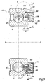
Figure 1 is a front view of an instrumented bearing according to the invention; -
Figure 2 is an exploded perspective view of a sensor body and a casing belonging to the instrumented bearing offigure 1 ; -
Figure 3 is a sectional view along line III-III, of the instrumented bearing offigure 1 ; -
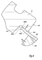
Figure 4 is a view, at a larger scale, of detail IV onfigure 3 . - The instrumented bearing 2 represented on the figures comprises a rolling
bearing 4 including a rotatinginner ring 42 and a fixedouter ring 44.Several balls 45 mounted in acage 46 are located betweeninner ring 42 andouter ring 44. In a non-shown alternate embodiment, rollingbearing 4 may comprise other types of rolling element, such as rollers or needles.Inner ring 42 is rotatable with respect toouter ring 44 around a central rotation axis X-X' of rolling bearing 4. - Instrumented bearing 2 also comprises a sensor unit. Sensor unit comprises an
encoder element 62, fast withinner ring 42 and adapted to generate magnetic field variations as a function of its angular position.Encoder element 62 comprises aframe 621 and amagnetic ring 623.Magnetic ring 623 is fixed toframe 621, which is fast in rotation withinner ring 42. - Sensor unit further comprises a
sensor body 64, which is mounted in a shielding casing oryoke 66 fixed toouter ring 44.Sensor body 64 is centred on a central axis X6 of sensor, which is aligned with axis X-X' whensensor body 64 is mounted onouter ring 44.Sensor body 64 comprises asensing element 640.Sensing element 640 is a transducer adapted to sense the magnetic field variations generated by the rotation of themagnetic ring 623 around axis X-X'.Sensing element 640 is mounted on and connected to a printed circuit board or PCB 642 thanks to asupport member 644. PCB 642 is mounted inshielding casing 66.Shielding casing 66 is an annular shaped metallic part centred on axis X6 and which comprises an innercylindrical wall 662, aradial bottom wall 664 perpendicular to axis X6 and an outercylindrical wall 666.Walls -
Shielding casing 66 can be made of synthetic material and/or metallic material such as steel or Aluminium. Axis X6 is a central axis forshielding casing 66. - PCB 642 has a half-annular shape corresponding with the shape of
shielding casing 66 and is mounted againstbottom wall 664. As an optional feature,sensor body 64 may comprise asupport plate 646, on which PCB 642 is mounted,support plate 646 being mounted againstbottom wall 664 ofshielding casing 66.Sensing element 640,support body 644, PCB 642 andsupport plate 646 are over-moulded in alayer 648 of plastic material injected inshielding casing 66. Alternatively, only sensingelement 640 and PCB 642 are overmoulded in thelayer 648 of plastic material; the element thus obtained is further glued onto theshielding casing 66, preferably onto itsbottom wall 664. -
Shielding casing 66 is directly fixed toouter ring 44 via outercylindrical wall 666. Outercylindrical wall 666 comprises alternated blockingportions 666a andsnap portions 666b, which extend on equal angular sectors with respect to axis X6 along the circumferential direction ofcasing 66.Portions casing 66. - α denotes the apex angle of an angular sector including a blocking
portion 666a, β denotes the apex angle of an angular sector including asnap portion 666b. Depending on the number of blockingportions 666b, the value of angle α and the value of angle β can vary and be adapted. - In the example of the figures, casing 66 includes five
blocking portions 666a and fivesnap portions 666b and angles α and β are both approximately equal to 30°. - Optionally, snap
portions 666b are substantially of the same length in the circumferential direction. In other words, apex angles β are equal to each other. In the same way, blockingportions 666a are optionally of the same length in the circumferential direction. In other words, apex angles α are equal to each other. - Blocking
portions 666a permit to accurately position casing 66 with respect to alateral surface 440 ofouter ring 44. As an optional embodiment,lateral surface 440 preferably extends perpendicularly to axis X-X'. An axial edge 666a1 of each blockingportion 666a abuts againstsurface 440 along axis X-X'. -
Snap portions 666b extend along axis X6 and protrude axially with respect to edges 666a1 towardsballs 45. Thus, snapportions 666b can be inserted insideouter ring 44, which comprises, on its inner surface, arecess 444. As an optional embodiment, surface is preferably cylindrical. P denotes a median plane ofbearing 4, this plane being perpendicular to axis X-X' and located mid-way betweenlateral surfaces outer ring 44. The diameter ofrecess 444 increases fromlateral surface 440 towards plane P. In a non-shown alternate embodiment,recess 444 can be replaced by a peripheral groove having the same function. - When not inserted in
recess 444, snapportions 666b have a diverging shape, with a diameter which increases from the annular portion ofwall 666 towards the free ends 666b1 ofsnap portions 666b. Thus, when not stressed byouter ring 44, the outer surface ofsnap portions 666b has a maximal diameter superior to the diameter ofrecess 444 at its minimal value, nearlateral surface 440. Therefore snapportions 666b exert an outwardly directed elastic force F onrecess 444, which guarantees the immobilization of casing 66 with respect toouter ring 44. More precisely, snapportions 666b guarantee the fastening in rotation of casing 66 withouter ring 44, by friction. - The
snap portions 666b guarantee also an accurate radial positioning of thesensor body 64 with respect to theencoder element 62. - Snap portions are provided, next to free ends 666b1, with end parts or noses 666b2 adapted to cooperate with a tapered
entry edge 444a ofrecess 444 upon mounting of casing 66 inouter ring 44. Inwardly bent noses 666b2 defines a curved outer surface which slides onedge 444a, provoking an elastic deformation ofsnap portions 666b towards axis X-X' when they are inserted insiderecess 444 along an axial direction parallel to axis X-X', as shown by arrow A1. When the insertion ofsnap portions 666b goes further, and until edges 666a1 come into abutment againstlateral surfaces 440, snapportions 666b expand into the larger portion ofrecess 444. - The combination of
snap portions 666b with blockingportions 666a permits to both fasten inrotation casing 66 toouter ring 44 and to accurately position sensingelement 640 with respect toencoder element 62, improving the sensing accuracy of sensor unit. - The alternation of
snap portions 666b and blockingportions 666a along the circumferential direction ofcasing 66, that is around axes X6 and X-X', permits a satisfying mounting stability. The separation between the two functions allows a better working efficiency for both of them. - In order to obtain an optimal mounting, casing 66 comprises five
blocking portions 666a alternated with fivesnap portions 666b. As a non-shown embodiment, casing 66 may comprise different numbers of blocking and snap portions, but comprises at least one blocking portion and one snapping portion and preferably two blocking portions and two snapping portions. - In an alternative embodiment, snap
portions 666b can be inserted outsideouter ring 44, in a recess made on its outer and preferably cylindrical surface. - According to a non-shown embodiment, the
casing 66 comprises an outercylindrical wall 666 but no radialbottom wall 664 nor innercylindrical wall 662. - According to another non-shown embodiment, the rotatable ring may be
outer ring 44, while casing 66 and sensing element may be fixed to non-rotatableinner ring 42. In such a case, the snap portions and the blocking portions can be provided on innercylindrical wall 662 ofcasing 66 and the recess is provided on the outer or inner preferably cylindrical surface of the inner ring. - The technical features of the embodiments and variants considered here-above can be combined.
Claims (15)
- An instrumented bearing (2) comprising a bearing (4) and a sensor unit for sensing the angular position of the rotatable ring (42) with respect to the fixed ring (44) of the bearing (4), said sensor unit comprising an encoder element (62) which is fast with the rotatable ring (42), and a sensing element (640) fast with the fixed ring (44), adapted to sense a parameter representative of the rotation speed of the rotatable ring (42), the sensing element (640) being mounted in a casing (66) fast with the fixed ring (44), wherein the casing (66) comprises a peripheral wall (666; 662) mounted on the fixed ring (44) and which includes at least one snap portion (666b) adapted to be received in a recess (444) of a surface of the fixed ring (44), charcaterized in that the peripheral wall (666; 662) also comprises at least one axial blocking portion (666a) adapted to abut against a lateral surface (440) of the fixed ring (44), and the or each snap portion (666b) and the or each blocking portion (666a) are alternated around a central axis (X6) of the casing (66).
- Instrumented bearing according to claim 1 wherein there are at least two snap portions (666b) and at least two blocking portions (666a).
- Instrumented bearing according to claim 2, wherein the blocking portions (666a) and the snap portions (666b) extend on alternate angular sectors.
- Instrumented bearing according to claim 3, wherein the snap portions (666b) are substantially of the same length in the circumferential direction.
- Instrumented bearing according to one of claims 3 and 4, wherein the blocking portions (666a) are substantially of the same length in the circumferential direction.
- Instrumented bearing according to any of claims 3 to 5, wherein the casing (66) comprises five snap portions (666b) and five blocking portions (666a), and wherein the apex angles (α, β) of said angular sectors have respectively a value approximately of 30°.
- Instrumented bearing according to any preceding claim, wherein the or each snap portion (666b) and the or each blocking portion (666a) are provided on a same wall (666 ; 662) of the casing (66).
- Instrumented bearing according to claim 7, wherein the wall (666, 662) is cylindrical and centred on the central axis (X6) of the casing (66).
- Instrumented bearing according to any preceding claim, wherein the fixed ring is the outer ring (44) of the bearing (4), wherein the recess (444) is provided on the inner cylindrical surface of the outer ring (44) and wherein the or each snap portion (666b) and the or each blocking portion (666a) are provided on an outer cylindrical wall (666) of the casing (66).
- Instrumented bearing according to claim 9, wherein the maximal diameter of the or each snap portion (666b), when non stressed by the outer ring (44), is superior to the minimal diameter of the recess (444).
- Instrumented bearing according to claim 10, wherein the recess (444) has a diameter, which increases from said lateral surface (440) towards a median plane (P) of the bearing (4).
- Instrumented bearing according to claim 11, wherein the or each snap portion (666b) have a diameter which increases towards a median plane (P) of the bearing (4).
- Instrumented bearing according to claim 12, wherein the or each snap portion (666b) has an inwardly bent end part (666b2) adapted to slide against a tapered entry edge (444a) of the recess (444).
- Instrumented bearing according to one of claims 1 to 8, wherein the fixed ring is the inner ring (42) of the bearing, wherein the recess is provided on the outer cylindrical surface of the inner ring (42) and wherein the snap portions (666b) and the blocking portions (666a) are provided on an inner cylindrical wall (662) of the casing (66).
- instrumented bearing according to any preceding claim, wherein the bearing (4) is of the rolling type and comprises rolling elements (45) located between the fixed ring (44) and the rotating ring (42).
Priority Applications (6)
| Application Number | Priority Date | Filing Date | Title |
|---|---|---|---|
| EP12305809.1A EP2682621B1 (en) | 2012-07-05 | 2012-07-05 | Instrumented bearing |
| IN2884CH2013 IN2013CH02884A (en) | 2012-07-05 | 2013-06-28 | |
| US13/934,559 US8950944B2 (en) | 2012-07-05 | 2013-07-03 | Instrumented bearing |
| JP2013140497A JP2014016030A (en) | 2012-07-05 | 2013-07-04 | Instrumented bearing |
| CN201310280785.8A CN103528497B (en) | 2012-07-05 | 2013-07-05 | Instrumentation bearing |
| KR1020130078693A KR20140005816A (en) | 2012-07-05 | 2013-07-05 | Instrumented bearing |
Applications Claiming Priority (1)
| Application Number | Priority Date | Filing Date | Title |
|---|---|---|---|
| EP12305809.1A EP2682621B1 (en) | 2012-07-05 | 2012-07-05 | Instrumented bearing |
Publications (2)
| Publication Number | Publication Date |
|---|---|
| EP2682621A1 EP2682621A1 (en) | 2014-01-08 |
| EP2682621B1 true EP2682621B1 (en) | 2015-02-25 |
Family
ID=46583915
Family Applications (1)
| Application Number | Title | Priority Date | Filing Date |
|---|---|---|---|
| EP12305809.1A Active EP2682621B1 (en) | 2012-07-05 | 2012-07-05 | Instrumented bearing |
Country Status (6)
| Country | Link |
|---|---|
| US (1) | US8950944B2 (en) |
| EP (1) | EP2682621B1 (en) |
| JP (1) | JP2014016030A (en) |
| KR (1) | KR20140005816A (en) |
| CN (1) | CN103528497B (en) |
| IN (1) | IN2013CH02884A (en) |
Cited By (1)
| Publication number | Priority date | Publication date | Assignee | Title |
|---|---|---|---|---|
| EP3124180A1 (en) | 2015-07-30 | 2017-02-01 | Aktiebolaget SKF | Tool and method for extracting a sensor unit from a bearing ring |
Families Citing this family (3)
| Publication number | Priority date | Publication date | Assignee | Title |
|---|---|---|---|---|
| FR3028901B1 (en) * | 2014-11-26 | 2017-04-14 | Skf Ab | INSTRUMENT BEARING AND METHOD OF MANUFACTURING SUCH AN INSTRUMENT BEARING |
| JP6724533B2 (en) * | 2016-05-09 | 2020-07-15 | 中西金属工業株式会社 | Radial magnetic encoder, bearing device including radial magnetic encoder, and method for manufacturing radial magnetic encoder |
| ES2914148T3 (en) * | 2018-07-18 | 2022-06-07 | Nke Austria Gmbh | Bearing monitoring system |
Family Cites Families (32)
| Publication number | Priority date | Publication date | Assignee | Title |
|---|---|---|---|---|
| IN149928B (en) * | 1977-07-22 | 1982-06-05 | Ransome Hoffmann Pollard | |
| DE3320063A1 (en) * | 1983-06-03 | 1984-12-06 | Skf Kugellagerfabriken Gmbh, 8720 Schweinfurt | SEALING RING FOR RADIAL ROLLER BEARING |
| IT1239872B (en) * | 1990-01-30 | 1993-11-15 | Skf Ind Spa | SPEED DETECTION DEVICE FOR DIVEICLE NON-DRIVE WHEELS. |
| IT1240481B (en) * | 1990-07-04 | 1993-12-17 | Skf Ind Spa | DEVICE SUITABLE FOR ALLOWING THE ROTATION SPEED TO BE DETECTED BETWEEN TWO BODIES IN RELATIVE ROTATION SUCH AS THE SUPPORT BODIES OF A WHEEL OF A VEHICLE. |
| FR2718805B1 (en) * | 1994-04-15 | 1996-06-07 | Skf France | Axial retaining member of a bearing with information sensor and bearing assembly comprising such a member. |
| JP3312531B2 (en) * | 1994-07-18 | 2002-08-12 | 日本精工株式会社 | Hub unit with rotation speed detector |
| FR2751707B1 (en) * | 1996-07-24 | 1998-09-11 | Skf France | INFORMATION SENSOR BEARING |
| IT1284997B1 (en) * | 1996-09-13 | 1998-05-28 | Skf Ind Spa | BEARING GROUP FOR RAILWAY AXLES OF FREIGHT WAGONS |
| JP2000192949A (en) * | 1998-10-21 | 2000-07-11 | Nsk Ltd | Rotary support device with rotating speed detecting device |
| FR2806764B1 (en) * | 2000-03-24 | 2002-08-23 | Skf France | INSTRUMENT ROLLING BEARING PROVIDED WITH A SEALING DEVICE |
| FR2807798B1 (en) * | 2000-04-12 | 2002-07-26 | Skf France | ANGULAR MOTION DETECTION DEVICE AND INSTRUMENTARY ROLLING BEARING |
| JP3869185B2 (en) * | 2000-06-13 | 2007-01-17 | 株式会社ジェイテクト | Seal ring, sealing device and rolling bearing incorporating the seal ring |
| FR2813644B1 (en) * | 2000-09-06 | 2003-01-24 | Skf France | INSTRUMENTED ROLLING BEARING DEVICE, PARTICULARLY FOR CONTROL WHEEL |
| US6559633B1 (en) * | 2000-09-18 | 2003-05-06 | Freudenberg-Nok General Partnership | Speed sensor with a seal |
| JP2003097580A (en) * | 2001-09-25 | 2003-04-03 | Koyo Seiko Co Ltd | Rolling bearing and method for manufacturing the same |
| DE10149642A1 (en) * | 2001-10-10 | 2003-04-24 | Freudenberg Carl Kg | Annular sensor housing |
| FR2841990B1 (en) * | 2002-07-02 | 2005-07-29 | Skf Ab | INSTRUMENTAL BEARING BEARING DEVICE AND ELECTRIC MOTOR THUS EQUIPPED |
| JP4244631B2 (en) | 2002-12-20 | 2009-03-25 | 株式会社ジェイテクト | Rolling bearing device |
| FR2851624B1 (en) * | 2003-02-26 | 2006-03-31 | Skf Ab | INSTRUMENT BEARING BEARING |
| JP2004340176A (en) * | 2003-05-13 | 2004-12-02 | Ntn Corp | Bearing with rotation sensor |
| JP2004232866A (en) * | 2004-02-23 | 2004-08-19 | Nsk Ltd | Rolling bearing unit with rotating speed detecting device |
| JP2005240838A (en) * | 2004-02-24 | 2005-09-08 | Koyo Seiko Co Ltd | Rolling bearing with sensor |
| JP2008002885A (en) * | 2006-06-21 | 2008-01-10 | Ntn Corp | Wheel bearing apparatus with wheel speed detector |
| DE102007001963B4 (en) * | 2007-01-13 | 2021-04-22 | Schaeffler Technologies AG & Co. KG | Rolling bearing with a device for draining off a liquid |
| DE102007042478A1 (en) * | 2007-02-14 | 2008-08-21 | Schaeffler Kg | Rolling bearing device with integrated sensor system |
| DE112008001568T5 (en) * | 2007-06-19 | 2010-08-12 | Ntn Corp. | A wheel bearing device connected to a wheel speed detecting device |
| US20100135605A1 (en) * | 2007-07-03 | 2010-06-03 | Yasuhiko Ishii | Sensor device and sensor-integrated rolling bearing device |
| US7628068B2 (en) * | 2007-10-24 | 2009-12-08 | Ashcroft, Inc. | Case, window and gasket for measuring device |
| DE102008009283B4 (en) * | 2008-02-15 | 2021-07-29 | Schaeffler Technologies AG & Co. KG | Wheel bearing device for a motor vehicle |
| US8710830B2 (en) * | 2009-05-19 | 2014-04-29 | Aktiebolaget Skf | Support member, rotation device comprising such a support and rolling bearing assembly including such a detection device |
| JP2012007706A (en) * | 2010-06-28 | 2012-01-12 | Nsk Ltd | Rolling bearing with sensor |
| DE102011003703A1 (en) * | 2011-02-07 | 2012-08-09 | Schaeffler Technologies Gmbh & Co. Kg | Measuring device for determining an operating state variable of a rotating component, in particular a bearing |
-
2012
- 2012-07-05 EP EP12305809.1A patent/EP2682621B1/en active Active
-
2013
- 2013-06-28 IN IN2884CH2013 patent/IN2013CH02884A/en unknown
- 2013-07-03 US US13/934,559 patent/US8950944B2/en active Active
- 2013-07-04 JP JP2013140497A patent/JP2014016030A/en active Pending
- 2013-07-05 CN CN201310280785.8A patent/CN103528497B/en active Active
- 2013-07-05 KR KR1020130078693A patent/KR20140005816A/en not_active Application Discontinuation
Cited By (1)
| Publication number | Priority date | Publication date | Assignee | Title |
|---|---|---|---|---|
| EP3124180A1 (en) | 2015-07-30 | 2017-02-01 | Aktiebolaget SKF | Tool and method for extracting a sensor unit from a bearing ring |
Also Published As
| Publication number | Publication date |
|---|---|
| US8950944B2 (en) | 2015-02-10 |
| CN103528497B (en) | 2018-04-06 |
| CN103528497A (en) | 2014-01-22 |
| IN2013CH02884A (en) | 2015-09-04 |
| JP2014016030A (en) | 2014-01-30 |
| EP2682621A1 (en) | 2014-01-08 |
| US20140010488A1 (en) | 2014-01-09 |
| KR20140005816A (en) | 2014-01-15 |
Similar Documents
| Publication | Publication Date | Title |
|---|---|---|
| EP2682621B1 (en) | Instrumented bearing | |
| CN108071674B (en) | Bearing unit comprising an impulse ring and device comprising at least one such bearing unit | |
| US9127718B2 (en) | Rotation detection set and bearing assembly comprising such a detection set | |
| US7290351B2 (en) | Mounting bracket, rolling bearing and corresponding assembly method | |
| US20080101741A1 (en) | Wheel bearing assemblies incorporating sensing arrangements | |
| US7270483B2 (en) | Rolling bearing unit | |
| EP2652447B1 (en) | Detection set comprising a support member, manufacturing method of such a detection set and bearing assembly including such a detection set | |
| US10324103B2 (en) | Impulse ring and a sensor-bearing unit comprising such impulse ring | |
| US9658049B2 (en) | Sensor head for an encoder | |
| US20060170414A1 (en) | Encoder for rolling contact bearings | |
| EP2602627A1 (en) | Speed sensor wheel with asymmetry for determining direction of rotation | |
| WO2012023000A1 (en) | Method for mounting a rolling bearing assembly on a vehicle and rolling bearing assembly adapted to such a method | |
| JP2009174704A (en) | Rolling bearing device with sensor | |
| WO2016000738A1 (en) | Impulse ring for a sensor bearing unit, and sensor bearing unit comprising such an impulse ring | |
| US20210246940A1 (en) | Roller bearing | |
| EP2682758B1 (en) | Sensor unit and instrumented bearing comprising such a sensor unit | |
| US11971071B2 (en) | Sensor bearing unit and associated apparatus | |
| JP2004176824A (en) | Sensor attaching structure for bearing device | |
| JP2006064145A (en) | Bearing device for wheel | |
| JP2004361362A (en) | Rolling bearing with rotation sensor | |
| JP2008116232A (en) | Magnetic encoder and rolling bearing | |
| JP2005055434A (en) | Pulse generator of device for detecting speed of shaft or hub | |
| JP2005188554A (en) | Bearing with rotary sensor | |
| EP1983306A1 (en) | Rotor for rotary encoder and rolling bearing for wheel having same | |
| EP2417462A1 (en) | Sensor assembly for a rolling bearing system, and a rolling bearing system comprising such a sensor assembly |
Legal Events
| Date | Code | Title | Description |
|---|---|---|---|
| PUAI | Public reference made under article 153(3) epc to a published international application that has entered the european phase |
Free format text: ORIGINAL CODE: 0009012 |
|
| AK | Designated contracting states |
Kind code of ref document: A1 Designated state(s): AL AT BE BG CH CY CZ DE DK EE ES FI FR GB GR HR HU IE IS IT LI LT LU LV MC MK MT NL NO PL PT RO RS SE SI SK SM TR |
|
| AX | Request for extension of the european patent |
Extension state: BA ME |
|
| 17P | Request for examination filed |
Effective date: 20140612 |
|
| RBV | Designated contracting states (corrected) |
Designated state(s): AL AT BE BG CH CY CZ DE DK EE ES FI FR GB GR HR HU IE IS IT LI LT LU LV MC MK MT NL NO PL PT RO RS SE SI SK SM TR |
|
| RIC1 | Information provided on ipc code assigned before grant |
Ipc: G01P 3/44 20060101ALI20140715BHEP Ipc: F16C 41/00 20060101AFI20140715BHEP |
|
| GRAP | Despatch of communication of intention to grant a patent |
Free format text: ORIGINAL CODE: EPIDOSNIGR1 |
|
| INTG | Intention to grant announced |
Effective date: 20140908 |
|
| INTG | Intention to grant announced |
Effective date: 20140915 |
|
| GRAS | Grant fee paid |
Free format text: ORIGINAL CODE: EPIDOSNIGR3 |
|
| GRAA | (expected) grant |
Free format text: ORIGINAL CODE: 0009210 |
|
| AK | Designated contracting states |
Kind code of ref document: B1 Designated state(s): AL AT BE BG CH CY CZ DE DK EE ES FI FR GB GR HR HU IE IS IT LI LT LU LV MC MK MT NL NO PL PT RO RS SE SI SK SM TR |
|
| REG | Reference to a national code |
Ref country code: GB Ref legal event code: FG4D |
|
| REG | Reference to a national code |
Ref country code: CH Ref legal event code: EP |
|
| REG | Reference to a national code |
Ref country code: IE Ref legal event code: FG4D |
|
| REG | Reference to a national code |
Ref country code: DE Ref legal event code: R096 Ref document number: 602012005447 Country of ref document: DE Effective date: 20150409 |
|
| REG | Reference to a national code |
Ref country code: AT Ref legal event code: REF Ref document number: 712255 Country of ref document: AT Kind code of ref document: T Effective date: 20150415 |
|
| REG | Reference to a national code |
Ref country code: NL Ref legal event code: VDEP Effective date: 20150225 |
|
| REG | Reference to a national code |
Ref country code: AT Ref legal event code: MK05 Ref document number: 712255 Country of ref document: AT Kind code of ref document: T Effective date: 20150225 |
|
| REG | Reference to a national code |
Ref country code: LT Ref legal event code: MG4D |
|
| PG25 | Lapsed in a contracting state [announced via postgrant information from national office to epo] |
Ref country code: HR Free format text: LAPSE BECAUSE OF FAILURE TO SUBMIT A TRANSLATION OF THE DESCRIPTION OR TO PAY THE FEE WITHIN THE PRESCRIBED TIME-LIMIT Effective date: 20150225 Ref country code: ES Free format text: LAPSE BECAUSE OF FAILURE TO SUBMIT A TRANSLATION OF THE DESCRIPTION OR TO PAY THE FEE WITHIN THE PRESCRIBED TIME-LIMIT Effective date: 20150225 Ref country code: LT Free format text: LAPSE BECAUSE OF FAILURE TO SUBMIT A TRANSLATION OF THE DESCRIPTION OR TO PAY THE FEE WITHIN THE PRESCRIBED TIME-LIMIT Effective date: 20150225 Ref country code: NO Free format text: LAPSE BECAUSE OF FAILURE TO SUBMIT A TRANSLATION OF THE DESCRIPTION OR TO PAY THE FEE WITHIN THE PRESCRIBED TIME-LIMIT Effective date: 20150525 Ref country code: FI Free format text: LAPSE BECAUSE OF FAILURE TO SUBMIT A TRANSLATION OF THE DESCRIPTION OR TO PAY THE FEE WITHIN THE PRESCRIBED TIME-LIMIT Effective date: 20150225 Ref country code: SE Free format text: LAPSE BECAUSE OF FAILURE TO SUBMIT A TRANSLATION OF THE DESCRIPTION OR TO PAY THE FEE WITHIN THE PRESCRIBED TIME-LIMIT Effective date: 20150225 |
|
| PG25 | Lapsed in a contracting state [announced via postgrant information from national office to epo] |
Ref country code: IS Free format text: LAPSE BECAUSE OF FAILURE TO SUBMIT A TRANSLATION OF THE DESCRIPTION OR TO PAY THE FEE WITHIN THE PRESCRIBED TIME-LIMIT Effective date: 20150625 Ref country code: LV Free format text: LAPSE BECAUSE OF FAILURE TO SUBMIT A TRANSLATION OF THE DESCRIPTION OR TO PAY THE FEE WITHIN THE PRESCRIBED TIME-LIMIT Effective date: 20150225 Ref country code: RS Free format text: LAPSE BECAUSE OF FAILURE TO SUBMIT A TRANSLATION OF THE DESCRIPTION OR TO PAY THE FEE WITHIN THE PRESCRIBED TIME-LIMIT Effective date: 20150225 Ref country code: GR Free format text: LAPSE BECAUSE OF FAILURE TO SUBMIT A TRANSLATION OF THE DESCRIPTION OR TO PAY THE FEE WITHIN THE PRESCRIBED TIME-LIMIT Effective date: 20150526 Ref country code: AT Free format text: LAPSE BECAUSE OF FAILURE TO SUBMIT A TRANSLATION OF THE DESCRIPTION OR TO PAY THE FEE WITHIN THE PRESCRIBED TIME-LIMIT Effective date: 20150225 |
|
| PG25 | Lapsed in a contracting state [announced via postgrant information from national office to epo] |
Ref country code: NL Free format text: LAPSE BECAUSE OF FAILURE TO SUBMIT A TRANSLATION OF THE DESCRIPTION OR TO PAY THE FEE WITHIN THE PRESCRIBED TIME-LIMIT Effective date: 20150225 |
|
| PG25 | Lapsed in a contracting state [announced via postgrant information from national office to epo] |
Ref country code: RO Free format text: LAPSE BECAUSE OF FAILURE TO SUBMIT A TRANSLATION OF THE DESCRIPTION OR TO PAY THE FEE WITHIN THE PRESCRIBED TIME-LIMIT Effective date: 20150225 Ref country code: DK Free format text: LAPSE BECAUSE OF FAILURE TO SUBMIT A TRANSLATION OF THE DESCRIPTION OR TO PAY THE FEE WITHIN THE PRESCRIBED TIME-LIMIT Effective date: 20150225 Ref country code: EE Free format text: LAPSE BECAUSE OF FAILURE TO SUBMIT A TRANSLATION OF THE DESCRIPTION OR TO PAY THE FEE WITHIN THE PRESCRIBED TIME-LIMIT Effective date: 20150225 Ref country code: SK Free format text: LAPSE BECAUSE OF FAILURE TO SUBMIT A TRANSLATION OF THE DESCRIPTION OR TO PAY THE FEE WITHIN THE PRESCRIBED TIME-LIMIT Effective date: 20150225 Ref country code: CZ Free format text: LAPSE BECAUSE OF FAILURE TO SUBMIT A TRANSLATION OF THE DESCRIPTION OR TO PAY THE FEE WITHIN THE PRESCRIBED TIME-LIMIT Effective date: 20150225 |
|
| REG | Reference to a national code |
Ref country code: DE Ref legal event code: R097 Ref document number: 602012005447 Country of ref document: DE |
|
| PG25 | Lapsed in a contracting state [announced via postgrant information from national office to epo] |
Ref country code: PL Free format text: LAPSE BECAUSE OF FAILURE TO SUBMIT A TRANSLATION OF THE DESCRIPTION OR TO PAY THE FEE WITHIN THE PRESCRIBED TIME-LIMIT Effective date: 20150225 |
|
| PLBE | No opposition filed within time limit |
Free format text: ORIGINAL CODE: 0009261 |
|
| STAA | Information on the status of an ep patent application or granted ep patent |
Free format text: STATUS: NO OPPOSITION FILED WITHIN TIME LIMIT |
|
| 26N | No opposition filed |
Effective date: 20151126 |
|
| PG25 | Lapsed in a contracting state [announced via postgrant information from national office to epo] |
Ref country code: MC Free format text: LAPSE BECAUSE OF FAILURE TO SUBMIT A TRANSLATION OF THE DESCRIPTION OR TO PAY THE FEE WITHIN THE PRESCRIBED TIME-LIMIT Effective date: 20150225 Ref country code: SI Free format text: LAPSE BECAUSE OF FAILURE TO SUBMIT A TRANSLATION OF THE DESCRIPTION OR TO PAY THE FEE WITHIN THE PRESCRIBED TIME-LIMIT Effective date: 20150225 |
|
| REG | Reference to a national code |
Ref country code: CH Ref legal event code: PL |
|
| PG25 | Lapsed in a contracting state [announced via postgrant information from national office to epo] |
Ref country code: LU Free format text: LAPSE BECAUSE OF FAILURE TO SUBMIT A TRANSLATION OF THE DESCRIPTION OR TO PAY THE FEE WITHIN THE PRESCRIBED TIME-LIMIT Effective date: 20150705 |
|
| REG | Reference to a national code |
Ref country code: IE Ref legal event code: MM4A |
|
| PG25 | Lapsed in a contracting state [announced via postgrant information from national office to epo] |
Ref country code: LI Free format text: LAPSE BECAUSE OF NON-PAYMENT OF DUE FEES Effective date: 20150731 Ref country code: CH Free format text: LAPSE BECAUSE OF NON-PAYMENT OF DUE FEES Effective date: 20150731 |
|
| PG25 | Lapsed in a contracting state [announced via postgrant information from national office to epo] |
Ref country code: BE Free format text: LAPSE BECAUSE OF FAILURE TO SUBMIT A TRANSLATION OF THE DESCRIPTION OR TO PAY THE FEE WITHIN THE PRESCRIBED TIME-LIMIT Effective date: 20150225 |
|
| REG | Reference to a national code |
Ref country code: FR Ref legal event code: PLFP Year of fee payment: 5 |
|
| PG25 | Lapsed in a contracting state [announced via postgrant information from national office to epo] |
Ref country code: IE Free format text: LAPSE BECAUSE OF NON-PAYMENT OF DUE FEES Effective date: 20150705 |
|
| GBPC | Gb: european patent ceased through non-payment of renewal fee |
Effective date: 20160705 |
|
| PG25 | Lapsed in a contracting state [announced via postgrant information from national office to epo] |
Ref country code: MT Free format text: LAPSE BECAUSE OF FAILURE TO SUBMIT A TRANSLATION OF THE DESCRIPTION OR TO PAY THE FEE WITHIN THE PRESCRIBED TIME-LIMIT Effective date: 20150225 |
|
| PG25 | Lapsed in a contracting state [announced via postgrant information from national office to epo] |
Ref country code: SM Free format text: LAPSE BECAUSE OF FAILURE TO SUBMIT A TRANSLATION OF THE DESCRIPTION OR TO PAY THE FEE WITHIN THE PRESCRIBED TIME-LIMIT Effective date: 20150225 Ref country code: HU Free format text: LAPSE BECAUSE OF FAILURE TO SUBMIT A TRANSLATION OF THE DESCRIPTION OR TO PAY THE FEE WITHIN THE PRESCRIBED TIME-LIMIT; INVALID AB INITIO Effective date: 20120705 Ref country code: BG Free format text: LAPSE BECAUSE OF FAILURE TO SUBMIT A TRANSLATION OF THE DESCRIPTION OR TO PAY THE FEE WITHIN THE PRESCRIBED TIME-LIMIT Effective date: 20150225 Ref country code: GB Free format text: LAPSE BECAUSE OF NON-PAYMENT OF DUE FEES Effective date: 20160705 |
|
| PG25 | Lapsed in a contracting state [announced via postgrant information from national office to epo] |
Ref country code: CY Free format text: LAPSE BECAUSE OF FAILURE TO SUBMIT A TRANSLATION OF THE DESCRIPTION OR TO PAY THE FEE WITHIN THE PRESCRIBED TIME-LIMIT Effective date: 20150225 |
|
| REG | Reference to a national code |
Ref country code: FR Ref legal event code: PLFP Year of fee payment: 6 |
|
| PG25 | Lapsed in a contracting state [announced via postgrant information from national office to epo] |
Ref country code: TR Free format text: LAPSE BECAUSE OF FAILURE TO SUBMIT A TRANSLATION OF THE DESCRIPTION OR TO PAY THE FEE WITHIN THE PRESCRIBED TIME-LIMIT Effective date: 20150225 Ref country code: MK Free format text: LAPSE BECAUSE OF FAILURE TO SUBMIT A TRANSLATION OF THE DESCRIPTION OR TO PAY THE FEE WITHIN THE PRESCRIBED TIME-LIMIT Effective date: 20150225 Ref country code: PT Free format text: LAPSE BECAUSE OF FAILURE TO SUBMIT A TRANSLATION OF THE DESCRIPTION OR TO PAY THE FEE WITHIN THE PRESCRIBED TIME-LIMIT Effective date: 20150225 |
|
| REG | Reference to a national code |
Ref country code: FR Ref legal event code: PLFP Year of fee payment: 7 |
|
| PG25 | Lapsed in a contracting state [announced via postgrant information from national office to epo] |
Ref country code: AL Free format text: LAPSE BECAUSE OF FAILURE TO SUBMIT A TRANSLATION OF THE DESCRIPTION OR TO PAY THE FEE WITHIN THE PRESCRIBED TIME-LIMIT Effective date: 20150225 |
|
| P01 | Opt-out of the competence of the unified patent court (upc) registered |
Effective date: 20230513 |
|
| PGFP | Annual fee paid to national office [announced via postgrant information from national office to epo] |
Ref country code: IT Payment date: 20230721 Year of fee payment: 12 |
|
| PGFP | Annual fee paid to national office [announced via postgrant information from national office to epo] |
Ref country code: FR Payment date: 20230725 Year of fee payment: 12 Ref country code: DE Payment date: 20230726 Year of fee payment: 12 |