EP2682603A1 - Hose reel pump with pivotable cover and medical device for extracorporeal blood treatment with hose reel pump - Google Patents
Hose reel pump with pivotable cover and medical device for extracorporeal blood treatment with hose reel pump Download PDFInfo
- Publication number
- EP2682603A1 EP2682603A1 EP13174610.9A EP13174610A EP2682603A1 EP 2682603 A1 EP2682603 A1 EP 2682603A1 EP 13174610 A EP13174610 A EP 13174610A EP 2682603 A1 EP2682603 A1 EP 2682603A1
- Authority
- EP
- European Patent Office
- Prior art keywords
- lid
- segment
- pump housing
- hose
- pump
- Prior art date
- Legal status (The legal status is an assumption and is not a legal conclusion. Google has not performed a legal analysis and makes no representation as to the accuracy of the status listed.)
- Granted
Links
- 239000008280 blood Substances 0.000 title claims abstract description 42
- 210000004369 blood Anatomy 0.000 title claims abstract description 42
- 230000017531 blood circulation Effects 0.000 claims description 4
- 239000008141 laxative Substances 0.000 claims description 3
- 230000002475 laxative effect Effects 0.000 claims description 3
- 230000002572 peristaltic effect Effects 0.000 claims 1
- 238000002560 therapeutic procedure Methods 0.000 description 13
- 238000000034 method Methods 0.000 description 8
- 230000008569 process Effects 0.000 description 8
- 238000012546 transfer Methods 0.000 description 8
- 238000000502 dialysis Methods 0.000 description 6
- 238000001514 detection method Methods 0.000 description 4
- 230000008901 benefit Effects 0.000 description 3
- 210000003811 finger Anatomy 0.000 description 3
- 238000003780 insertion Methods 0.000 description 3
- 230000037431 insertion Effects 0.000 description 3
- 230000007246 mechanism Effects 0.000 description 3
- 230000006378 damage Effects 0.000 description 2
- 230000001419 dependent effect Effects 0.000 description 2
- 238000011161 development Methods 0.000 description 2
- 230000018109 developmental process Effects 0.000 description 2
- 206010018910 Haemolysis Diseases 0.000 description 1
- 208000027418 Wounds and injury Diseases 0.000 description 1
- 230000004888 barrier function Effects 0.000 description 1
- 230000004087 circulation Effects 0.000 description 1
- 238000007599 discharging Methods 0.000 description 1
- 239000013013 elastic material Substances 0.000 description 1
- 230000008588 hemolysis Effects 0.000 description 1
- 208000014674 injury Diseases 0.000 description 1
- 238000012544 monitoring process Methods 0.000 description 1
- 230000001105 regulatory effect Effects 0.000 description 1
- 230000008719 thickening Effects 0.000 description 1
- 210000003813 thumb Anatomy 0.000 description 1
Images


Classifications
-
- A—HUMAN NECESSITIES
- A61—MEDICAL OR VETERINARY SCIENCE; HYGIENE
- A61M—DEVICES FOR INTRODUCING MEDIA INTO, OR ONTO, THE BODY; DEVICES FOR TRANSDUCING BODY MEDIA OR FOR TAKING MEDIA FROM THE BODY; DEVICES FOR PRODUCING OR ENDING SLEEP OR STUPOR
- A61M1/00—Suction or pumping devices for medical purposes; Devices for carrying-off, for treatment of, or for carrying-over, body-liquids; Drainage systems
- A61M1/14—Dialysis systems; Artificial kidneys; Blood oxygenators ; Reciprocating systems for treatment of body fluids, e.g. single needle systems for hemofiltration or pheresis
- A61M1/30—Single needle dialysis ; Reciprocating systems, alternately withdrawing blood from and returning it to the patient, e.g. single-lumen-needle dialysis or single needle systems for hemofiltration or pheresis
-
- F—MECHANICAL ENGINEERING; LIGHTING; HEATING; WEAPONS; BLASTING
- F04—POSITIVE - DISPLACEMENT MACHINES FOR LIQUIDS; PUMPS FOR LIQUIDS OR ELASTIC FLUIDS
- F04B—POSITIVE-DISPLACEMENT MACHINES FOR LIQUIDS; PUMPS
- F04B43/00—Machines, pumps, or pumping installations having flexible working members
- F04B43/12—Machines, pumps, or pumping installations having flexible working members having peristaltic action
- F04B43/1253—Machines, pumps, or pumping installations having flexible working members having peristaltic action by using two or more rollers as squeezing elements, the rollers moving on an arc of a circle during squeezing
Definitions
- the invention relates to a hose reel pump for a medical device for extracorporeal blood treatment, comprising a pump housing having a curved tread and a rotatable within the tread rotor, wherein a hose segment looped between the tread and the rotor can be introduced and the pump housing means for attaching the hose segment are provided, with which at least one end of the hose segment about an axis of rotation is pivotally attachable to the pump housing.
- the pivoting of the tube segment can be carried out by pivoting a tilting element, to which the tube segment is at least partially attached.
- the invention further relates to a medical device for extracorporeal blood treatment with such a tube roller pump.
- tube roller pumps In medical devices for extracorporeal blood treatment (dialysis), tube roller pumps are often used, which convey the withdrawn blood of the patient back to a dialyzer and to the patient.
- hose roller pumps work peristaltically, wherein a loop-shaped hose segment rests against a correspondingly curved running surface of the pump housing.
- a lying inside the tread rotor of the pump then moves with its outer edges along the tube segment, where it pushes the tube locally and thus allows the elastic material properties of the tube segment, a blood delivery through the tube segment.
- the blood is supplied to the tube segment via a first connection and removed again via a further connection at the other end of the tube segment.
- the hose segment thus forms, for example, together with the incoming and outgoing lines and a plurality of air traps, a so-called transfer system, with which the patient's blood is conveyed back to a dialyzer and to the patient.
- Transfer systems are preferably replaced after each treatment and are not reused for other patients.
- a used hose segment must thus be removed from the pump before a new transfer system is introduced into the device.
- a holding device in this case has a clamping device with at least one pivotable clamping jaw, which has a semicircular recess, so that a hose can be held in this semicircular recess and an opposite, also semicircular recess of another jaw.
- the jaws may also have a plurality of these recesses so that a plurality of tubes can be accommodated simultaneously.
- multiconnectors which unite both connections for incoming and outgoing lines in a component, which can then be introduced into a receptacle of the pump housing. Its presence in the pump can also be detected via the geometric shape of such multiconnectors by, for example, actuating a cylindrical section of the multiconnector during the insertion process, a ram whose axial position is interrogated via a light barrier. At the same time, this plunger is part of a pump housing mounted electromechanical actuator, which can eject the multi-connector via a linear drive.
- the pump is usually concealed with a hinged lid that can be manually closed or opened by the operator.
- the cover thus forms an engagement guard to prevent interference with the pump during motorized rotation of the rotor, which could result in injury and damage to the pump.
- the object of the invention is also to provide a medical device for extracorporeal blood treatment with such a tube roller pump.
- this object is achieved by a hose roller pump according to independent claim 1.
- Advantageous developments of the hose roller pump will become apparent from the dependent claims 2-15.
- the task becomes further solved by a medical device for extracorporeal blood treatment according to claim 16.
- the hose reel pump according to the invention is suitable for a medical device for extracorporeal blood treatment and comprises a pump housing, which has a curved running surface and a rotatable within the tread rotor, wherein a tubular segment between the tread and the rotor can be introduced looped and on the pump housing means for releasable attachment or are provided for holding the tube segment, with which at least a portion or an end portion of the tube segment can be pivoted about an axis of rotation with respect to the pump housing.
- the pivoting of the tube segment can be carried out by pivoting a tilting element, to which the tube segment is at least partially attached or which holds a part of the tube segment.
- the hose roller pump has a cover which is pivotally mounted on the pump housing and with which the pump housing is at least partially covered, wherein the lid is formed and attached to the pump housing, that in the closed state upon pivoting of the tube segment in the direction of the closed lid forms an abutment for the tilting element, by which the hose segment attached thereto in a defined position relative to the pump housing can be aligned.
- the hose roller pump has at least means for automatically unthreading the hose segment from the running surface in this defined position.
- the pump according to the invention thus has a lid which also supports the attachment of the tube segment and at least the automated Ausfädelvorgang, since it forms a counter-bearing in the closed state against which a tilting element can be pulled, which the tube segment in a defined Ausfädelposition brings.
- the lid serves as a stop and also provides space to pivot the tilting can.
- the lid allows in the closed state, a pivoting of the tilting member and held therein part of the tube segment.
- the lid can be designed that way be that the lid defines a pivotal space in the closed state, which essentially allows only a certain and desired pivotal movement of the tilting element between a threading position and a Ausfädelposition the hose segment.
- the tilting element can be designed in various ways.
- the tilting element may be an integral part of the hose roller pump and may have means for releasably attaching at least one end of the hose segment. Both ends of the tube segment can then be temporarily attached to the tilting element and be changed by pivoting the tilting element about an axis of rotation in their position.
- the tilting member has means for releasably attaching one end of the hose segment, while means are provided on the pump housing for releasably attaching the other end of the hose segment. The first end of the hose segment is thus fixed to the pump housing, while the other end can be moved by pivoting the tilting element.
- the fixed first receptacle in particular has the advantage that this receptacle is not raised or lowered, but is fixed to the pump housing so that no pinching of the tube occurs in this area.
- the fixed first receptacle is preferably that receptacle in the direction of which the tube is easily pushed during threading through the at least one guide pin.
- this is releasably and pivotally attached to the pump housing by being insertable into a receptacle on the pump housing, which forms a pivot bearing for the tilting element, wherein the pivot bearing is arranged in the region of one end of the hose segment.
- the tilting element in this embodiment is a separate component, which is only temporarily attached to the pump housing.
- the hose segment and the incoming and outgoing lines can be firmly connected to this tilting element, which then performs the function of a multi-connector between the hose segment and the on and discharging lines.
- the tilting element can also be designed as a reusable adapter to which a standard tube system is attached only for therapy. For this purpose, the adapter has appropriate recordings.
- the axis of rotation of the lid and the pivot axis of the tilting element can be perpendicular to each other.
- the lid of the pump may have on its inside, which faces the respective tilting element in the closed state, a pressure surface which rests in the region of the pivot bearing on the tilting element and / or the hose segment.
- the lid can be used to hold a connector and / or a part of the tube segment in the region of the axis of rotation of the tilting element in position when the tilting element is pivoted away from the pump housing.
- the tilting element or the hose segment can thus not be released from the corresponding receptacle, since the cover presses against it, so that the cover thereby also has a security function in addition to the function as intervention protection.
- the tilting member is pivotally mounted about a rotational axis on the pump housing, which extends transversely to the axis of rotation of the lid on the pump housing.
- the axis of rotation of the lid extends vertically, while the axis of rotation of the tilting element is horizontal. The lid can then be easily swung to the side, while the insertion and pivoting of the tilting element can be performed by ergonomic hand movements.
- the tilting element To be able to move the tilting element manually by an operator, it is at least partially accessible from the outside when the lid is closed. It is preferably accessible from a side with the lid closed, which lies opposite the axis of rotation of the lid.
- the geometry of the tilting element forms a gripping surface, with which the tilting element can be pulled against the closed lid.
- the geometry of the lid then forms according to his Outside, which faces away from the tilting element in the closed state, a gripping surface, which stands at contact of the tilting element with the lid as an abutment at a distance from the gripping surface of the tilting element, which is greater than 3mm.
- the operator of the pump must thus bring his fingers not closer than 3mm to each other when pulling the tilting element against the lid, otherwise this would be uncomfortable and ergonomically unfavorable.
- this distance is more on the order of 5mm to 20mm.
- the geometry of the tilting element and the geometry of the lid can be coordinated so that the tilting element abuts after pivoting against the closed lid as an abutment surface on a contact surface of the lid.
- a stop is formed by the lid, which can be safely detected by the operator as an end stop.
- the cover has in regions a hollow bulge in a direction facing away from the pump housing in the closed state of the lid.
- the tube segment may come to rest before automated threading or after automated unthreading after the lid has already been closed.
- the lid can thus be closed, without the hose segment between the rotor and lid is crushed, or the height of the pump housing must be significantly increased to provide sufficient space for the hose segment.
- the side contour of the hollow bulge follows in the closed state of the lid substantially the contour of the tread, since in this area additional space for the hose segment is needed, especially after it has been threaded out.
- the hollow bulge can flatten in the direction of the tilting element in the closed state of the lid.
- the invention further comprises a medical device for extracorporeal blood treatment, comprising at least one tube roller pump with a pump housing, which has a curved tread and a rotor rotating within the tread, wherein a tube segment of an extracorporeal Blood circulation between the tread and the rotor can be introduced, and the hose segment blood can be supplied via a supply line, while blood is discharged from the tube segment via a laxative line.
- the device comprises a tube roller pump according to one of the described embodiments.
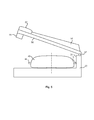
- Fig. 1 shows a schematic representation of the essential basic components of a medical device 10 for extracorporeal blood treatment with a blood pump, wherein the blood pump is a tube roller pump.
- the hose roller pump in this case has a pump housing 20, which is typically mounted on the front side of the dialysis machine 10.
- This tube roller pump is supplied to arterial blood 31 of a patient and conveyed through the extracorporeal blood circulation. Subsequently, the blood is returned as venous blood 32 back to the patient.
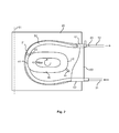
- the blood is pumped by the pump through a transfer system which is connected to several components of the dialysis machine 10, wherein a tube segment 30 of the transfer system is inserted into the blood pump and a rotor 40 promotes the blood peristaltically through this tube segment 30, as an enlarged View of Fig. 2 can be seen.
- the blood After passing through the blood pump, the blood reaches the dialyzer 13, after having preferably previously passed through an arterial air trap 11.
- the blood is purified by mass transfer with a dialysate 14, which is the dialyzer 13 and discharged.
- a dialysate 14 After passing through the dialyzer 13 passes Blood to a venous air trap 12 and is then supplied to the patient. This circulation of the patient's blood is in Fig. 1 indicated by arrows.
- the setting of parameters of the dialysis and the monitoring of the therapy can be done via a display / input unit 15, which is preferably designed as a touch screen. Furthermore, the dialysis machine 10 has a control / regulating unit 16.
- FIG. 3 shows a schematic representation of a tube roller pump with inserted tube segment 30 and a first embodiment of a tilting element which is designed as a multi-connector 60, to which both the tube segment 30 and the supply and discharge lines 31 and 32 of the extracorporeal blood circuit are connected.
- the hose reel pump in this case has the pump housing 20, which is easily accessible to the operator of the device, wherein the pump housing 20 with a (in Fig. 2 not shown) cover 50 can be covered, which is preferably pivotable about a pivot axis 51 to the left to gain access to the pump.
- a curved running surface 21 is formed by a recess in the housing, in which the hose segment 30 can be inserted in a loop shape, so that its two hose ends protrude from the housing 20.
- the recess may be formed with a side surface in the pump housing 20, which runs substantially uniformly perpendicular to the front side of the device, or the tread 21 is unevenly formed by a side surface of the recess, which is concave or even twisted formed.
- a rotor 40 which has an elliptical circumference so that it can easily compress the hose segment 30 during rotation at its main crests 41, 42 and rollers (not shown) attached thereto.
- the area of a compressed tube segment also moves clockwise until the associated major vertex disengages from the tube segment.
- the opposite major vertex has already re-contacted the tube segment 30, so that blood is in each case in the region of the Tube segment 30, in which it is compressed by the rotor 40, is peristaltically pumped from the pump inlet to the pump outlet.
- the multi-connector 60 is a separate component, which may be an integral part of the disposable article, so that the multi-connector 60 is pivotally mounted together with the hose system on the pump. In an alternative embodiment of the multi-connector this is designed as a reusable adapter to which a standard hose system can be temporarily mounted to mount it to the pump can.
- the multi-connector 60 includes a body interconnecting two opposing connector elements 61 and 62, which may also be referred to as connectors.
- At least the connector element 61 is cylindrical, or has at least one cylindrical area on its outer surface. In this way, this connector element 61 can be introduced into a correspondingly shaped receptacle in the pump housing 20, whereby a rotary bearing with a rotation axis 63 results around which the multi-connector 60 is pivotable.
- the second connector element 62 is preferably also cylindrically shaped, which may also be a cylinder with stepped outer surfaces. The cylinder axes of the two connector elements 61, 62 run parallel to each other, so that the two lines 31, 32 are also performed in parallel in the pump or from the pump.
- the multi-connector 60 is thus in Fig. 2 pivotable about the axis of rotation on the connector element 61 out of the plane of the drawing.
- the pivoted position means are provided, with which the multi-connector 60 can be latched on the pump housing 20.
- the second connector element 62 is shaped so that it engages in a receptacle in the pump housing 20 when it is pressed against the pump housing 20. But it can also be easily removed from this shot are solved when the multi-connector 10 from the drawing plane of Fig. 2 is swung out.
- the main body of the multi-pin 60 is therefore preferably slightly elastic, so that it allows snapping into a receptacle. However, it can also be made relatively stiff, in which case the recording in the pump housing 20 would be elastic.
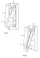
- the surfaces of the multi-connector 60 may include geometric codings to position the multi-connector 60 on the pump. Furthermore, surfaces can be formed as gripping surfaces with which the multi-connector 60 can be gripped and mounted as simply and ergonomically as possible. To explain the process of pivoting about the axis of rotation 63 in more detail, show the FIGS. 3a and 3b in each case a schematic side view of the hose roller pump with mounted multi-connector 60 and a cover 50.
- FIG. 3a It shows Fig. 3a an inserted multi-connector 60, the upper connector element 61 is inserted into a semicircular receptacle 22 in the pump housing 20. Due to the cylindrical shape of the connector element 61 and the receptacle 22 results at this point a pivot point about which the multi-connector 60 is pivotable. In this case, the lower connector element 62 is also engaged in a receptacle. This can be achieved for example by a semicircular receptacle 23, which forms a latching mechanism together with the geometry of the multi-pin 60. However, a latching can also be done on other components.
- a semicircular receptacle 23 which forms a latching mechanism together with the geometry of the multi-pin 60.
- a latching can also be done on other components.
- FIG. 3a The situation shown is the therapy position of the multi-connector 60, for which the tube segment (not shown) attached to the multi-connector 60 has been automatically threaded. Previously, the lid 50
- the cover 50 has a base body whose geometry forms different functional areas. For example, the cover 50 on the outside of a bulge 54 and a gripping surface 52. On the opposite side of this gripping surface 52, a contact surface 53 is formed on the inside of the lid 50, to which the multi-pin 60 abuts when it is pivoted to the Ausfädelposition. This is in the presentation of Fig. 3b shown. The same goes for the Pressure surface 55 in the region of the pivot bearing, which rests in the Ausfädelposition to the upper portion of the multi-pin 60 and thus prevents falling out of the multi-pin 60 from the upper receptacle 22.
- the gripping surface 52 mainly serves as an abutment or operating and actuating surface for actuating the respective tilting element.
- this grip surface 52 can also be used to open the lid 50, but preferably the geometry of the lid 50 in the region of the pressure surface 55 is formed so that forms a further gripping surface with which the lid 50 can be opened better.
- this gripping surface 56 may be bent slightly outward as shown in the three-dimensional view of FIG Fig. 8 can be seen.
- the user can grip with one hand the gripping surface 52 on the cover 50 and the gripping surface 64 on the multi-connector 60. He may, for example, put his thumb on the gripping surface 52 of the lid 50 and grip with one or more of the other fingers under the gripping surface 64 on the multi-connector 60 so that he can pull the multi-connector 60 with these fingers against the lid 50, then a Forms an abutment.
- This pivoting process is in the Fig. 3b represented by an arrow.
- the location of the multi-connector 60 according to Fig. 3b represents for the tube segment 30 attached thereto the Ausfädelposition, in which one or more guide pins can lift the tube segment 30 upon rotation of the rotor 40 from the tread.
- a spring mechanism may be provided at the upper pivot bearing.
- the lid 50 may remain closed with the lifted-out tube segment 30 within the bulge 54 of the lid after being unthreaded. Subsequently, the lid 50 can be opened and the multi-connector 60 can be removed together with the hose segment 30 from the pump by the latch in the upper receptacle 22 is released.
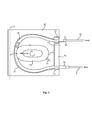
- FIG. 2 shows a schematic representation of a hose roller pump with inserted hose segment 30 and a second embodiment of a tilting element, which is designed as a rocker arm 70.
- This rocker arm 70 is in this case an integral part of the pump, but the basic structure of the hose roller pump corresponds to that already on the basis of Fig. 2 described structure.
- the hose segment 30 is connected via individual connecting elements 33 and 34 to a supply line 31 and a discharge line 32, as is the case with standard transfer systems.
- One end of the tube segment 30 is introduced into a first receptacle 24, which is formed in the upper region of the pump housing 20.
- This receptacle 24 is firmly integrated into the pump housing 20 and designed, for example, as a hollow cylinder with a longitudinal slot, so that the tube segment 30 can be pressed into this longitudinal slot.
- the rocker arm 70 is mounted, which is rotatable about a pivot axis 72.
- a second receptacle 71 is formed, which can also be realized by a hollow cylinder with longitudinal section. In this longitudinal section, the other end of the tube segment 30 is pressed.
- the connectors 33 and 34 are on the outside of the receptacles 24 and 71, so that the incoming and outgoing lines 31, 32 can not be drawn into the pump.
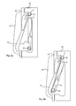
- FIGS. 5a and 5b show the rocker arm 70 analogous to the FIGS. 3a and 3b in the therapy position or threading position and in the Ausfädelposition in which the lower end of the tube segment 30 is far away from the pump bottom, that a guide pin on the rotor 40 can perform the automatic unthreading.
- the tube segment 30 is pressed into the upper receptacle 24, which is fixed to the pump housing and the other end of the tube segment 30 is pressed into the lower receptacle 71 on the rocker arm 70.
- a gripping surface 73 may be formed, so that the rocker arm 70 can be pulled over the axis of rotation 72 in the direction of the closed cover 50.
- the contact surface 53 of the lid 50 again forms an abutment for the rocker arm 70 in the Ausfädelposition.
- the Fig. 5b can the upper pressure surface 55 of the lid 50 abut the hose segment 30 to prevent slipping out of this region of the hose segment 30 from the receptacle 24.
- a further locking mechanism may be provided to hold the rocker arm 70 in this position.
- detection means may be provided to directly detect the position of the respective tilting member in the engaged threading position. This Einfädelposition also represents the therapy position. After locking the tilting element in this position, the lid 50 is closed and the automated threading process can be started. Preferably, detection means are also provided for detecting the state of the lid 50, so that the threading process can be started as soon as it is ensured via the detection means that the tilting element is in the threading position and the lid is closed.
- the rotor 40 When threading the rotor 40 is rotated slowly, so that the guide pins 41 and 42 perform the threading. In this case, at least one guide pin moves outward along the tube segment 30 and pushes it between the rotor 40 and the running surface 21.
- the tilting element is pulled by a user together with the tube segment 30 against the cover 50.
- the lid 50 serves as an abutment, against which the tilting element can be pulled to the stop. This stop defines the Ausfädelposition, which can also be detected by detection means. With the lid 50 closed and the respective tilting member in the threading position, the rotor 40 can slowly move the guide pins between the pump bottom and the hose segment 30, thereby lifting the hose segment 30 out of the gap between the rotor 40 and the tread 21.
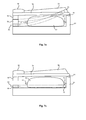
- Fig. 6 shows a schematic cross section through a hose reel pump with a slightly open lid, wherein the lid 50 is pivoted about the axis of rotation 51 to the front and no hose segment has been inserted. From this view, it can also be seen that the bulge 54 on the outside of the lid 50 preferably flattened in the direction of the gripping surface 52, since the space of the bulge 54 in the other direction must be greatest in order to accommodate the hose segment before threading or after unthreading.
- Fig. 7a shows the cross section of the tube roller pump with the lid closed 50, wherein the tube segment 30 is attached by way of example to a multi-connector 60, which rests in the Ausfädelposition on the lid 50. Since it is a view from above, the schematic representation of the Fig. 7a Also, that the upper pressure surface 55 of the lid 50 rests against the upper connector of the multi-pin 60.
- the tube segment 30 extends within the pump housing 20 and the bulge 54 in the cover 50, wherein the course of the tube segment 30 is shown in dashed lines. In order to lift the hose segment 30 in this position, at least one guide pin 43, 44 has moved between the hose segment 30 and the bottom of the pump housing 20 when rotating the rotor 40.
- Fig. 7b shows the cross section of the tube roller pump with the lid closed 50, wherein the multi-connector 60 has been brought into the threading and the tube segment 30 is already threaded between the rotor 40 and the tread 21.
- at least one guide pin 43, 44 has moved between the hose segment 30 and the cover 50 during rotation of the rotor 40.
- the shows Fig. 8 a three-dimensional view of the lid 50 with the hollow protrusion 54 and the outer gripping surface 52.
- the abutment surface 53 is formed and the pressure surface 55 is formed by a hollow thickening in this area.
- the cover on the opposite side forms the gripping surface 56 for opening the lid 50. It can also be seen how the bulge 54 flattens in the direction of the gripping surface 52.
Landscapes
- Health & Medical Sciences (AREA)
- Engineering & Computer Science (AREA)
- Urology & Nephrology (AREA)
- Heart & Thoracic Surgery (AREA)
- Hematology (AREA)
- Vascular Medicine (AREA)
- Anesthesiology (AREA)
- Biomedical Technology (AREA)
- Emergency Medicine (AREA)
- Life Sciences & Earth Sciences (AREA)
- Animal Behavior & Ethology (AREA)
- General Health & Medical Sciences (AREA)
- Public Health (AREA)
- Veterinary Medicine (AREA)
- Mechanical Engineering (AREA)
- General Engineering & Computer Science (AREA)
- External Artificial Organs (AREA)
Abstract
Description
Die Erfindung betrifft eine Schlauchrollenpumpe für ein medizinisches Gerät zur extrakorporalen Blutbehandlung, umfassend ein Pumpengehäuse, das eine gebogene Lauffläche und einen innerhalb der Lauffläche drehbaren Rotor aufweist, wobei ein Schlauchsegment schlaufenförmig zwischen die Lauffläche und den Rotor einbringbar ist und am Pumpengehäuse Mittel zur Anbringung des Schlauchsegments vorgesehen sind, mit denen wenigstens ein Ende des Schlauchsegments um eine Drehachse schwenkbar am Pumpengehäuse anbringbar ist. Dabei ist das Verschwenken des Schlauchsegments durch Verschwenken eines Kippelements durchführbar, an dem das Schlauchsegment wenigstens teilweise angebracht ist.The invention relates to a hose reel pump for a medical device for extracorporeal blood treatment, comprising a pump housing having a curved tread and a rotatable within the tread rotor, wherein a hose segment looped between the tread and the rotor can be introduced and the pump housing means for attaching the hose segment are provided, with which at least one end of the hose segment about an axis of rotation is pivotally attachable to the pump housing. In this case, the pivoting of the tube segment can be carried out by pivoting a tilting element, to which the tube segment is at least partially attached.
Die Erfindung betrifft ferner ein medizinisches Gerät zur extrakorporalen Blutbehandlung mit einer solchen Schlauchrollenpumpe.The invention further relates to a medical device for extracorporeal blood treatment with such a tube roller pump.
In medizinischen Geräten zur extrakorporalen Blutbehandlung (Dialyse) werden oftmals Schlauchrollenpumpen eingesetzt, welche das entnommene Blut des Patienten zu einem Dialysator und zum Patienten zurückfördern. Solche Schlauchrollenpumpen arbeiten peristaltisch, wobei ein schlaufenförmiges Schlauchsegment an einer entsprechend gebogenen Lauffläche des Pumpengehäuses anliegt. Ein innerhalb der Lauffläche liegender Rotor der Pumpe bewegt sich dann mit seinen Außenkanten entlang des Schlauchsegments, wobei es den Schlauch lokal eindrückt und so mit den elastischen Materialeigenschaften des Schlauchsegments eine Blutförderung durch das Schlauchsegment ermöglicht. Dafür wird das Blut dem Schlauchsegment über einen ersten Anschluss zugeführt und über einen weiteren Anschluss am anderen Ende des Schlauchsegments wieder abgeführt.In medical devices for extracorporeal blood treatment (dialysis), tube roller pumps are often used, which convey the withdrawn blood of the patient back to a dialyzer and to the patient. Such hose roller pumps work peristaltically, wherein a loop-shaped hose segment rests against a correspondingly curved running surface of the pump housing. A lying inside the tread rotor of the pump then moves with its outer edges along the tube segment, where it pushes the tube locally and thus allows the elastic material properties of the tube segment, a blood delivery through the tube segment. For this, the blood is supplied to the tube segment via a first connection and removed again via a further connection at the other end of the tube segment.
Das Schlauchsegment bildet so beispielsweise zusammen mit den zu- und abführenden Leitungen und mehreren Luftfängern ein sogenanntes Überleitsystem, mit dem Blut des Patienten zu einem Dialysator und zum Patienten zurückgefördert wird. DerartigeThe hose segment thus forms, for example, together with the incoming and outgoing lines and a plurality of air traps, a so-called transfer system, with which the patient's blood is conveyed back to a dialyzer and to the patient. such
Überleitsysteme werden vorzugsweise nach jeder Behandlung ausgetauscht und nicht wieder für andere Patienten verwendet. Ein benutztes Schlauchsegment muss somit aus der Pumpe entfernt werden, bevor ein neues Überleitsystem in das Gerät eingebracht wird. Um die Handhabung während dieses Ablegens und Aufrüstens des Überleitsystems zu erleichtern, ist es ferner bekannt, an beiden Enden des Schlauchsegments jeweils einen Konnektor vorzusehen, der mit einer zu- bzw. abführenden Leitung verbunden werden kann.Transfer systems are preferably replaced after each treatment and are not reused for other patients. A used hose segment must thus be removed from the pump before a new transfer system is introduced into the device. In order to facilitate the handling during this storing and upgrading of the transfer system, it is also known to provide a connector at both ends of the hose segment, which can be connected to an incoming or outgoing line.
Zur Aufnahme eines Schlauchs innerhalb einer Rollenpumpe beschreibt beispielsweise das Patent
Darüber hinaus sind automatische Systeme bekannt, die das Ein- und Ausfädeln des Schlauchs in die Pumpe übernehmen und somit erleichtern sollen. Oftmals ist dabei zum Ausfädeln ein Aktuator zu betätigen, der das System beispielsweise über einen Linearantrieb aus seiner Therapieposition in eine Ausfädelposition bewegt. Hierzu kann es bei solchen Systemen erforderlich sein, einen Schalter/Knopf an dem medizinischen Gerät zu bedienen bzw. einen Softwarebutton auf einer Benutzeroberfläche zu berühren.In addition, automatic systems are known to take over the threading and unthreading of the hose in the pump and thus facilitate. Often, an actuator is to operate for unthreading, which moves the system, for example via a linear drive from its therapy position in a Ausfädelposition. For this purpose, it may be necessary in such systems to operate a switch / button on the medical device or to touch a software button on a user interface.
Ferner sind Multikonnektoren bekannt, die beide Anschlüsse für zu- bzw. abführende Leitungen in einem Bauteil vereinigen, das dann in eine Aufnahme des Pumpengehäuses eingebracht werden kann. Über die geometrische Form derartiger Multikonnektoren kann auch ihre Präsenz in der Pumpe detektiert werden, indem beispielsweise ein zylindrischer Abschnitt des Multikonnektors während des Einsetzvorgangs einen Stößel betätigt, dessen axiale Position über eine Lichtschranke abgefragt wird. Gleichzeitig ist dieser Stößel Bestandteil eines im Pumpengehäuse montierten elektromechanischen Aktuators, der den Multikonnektor über einen Linearantrieb auswerfen kann.Furthermore, multiconnectors are known, which unite both connections for incoming and outgoing lines in a component, which can then be introduced into a receptacle of the pump housing. Its presence in the pump can also be detected via the geometric shape of such multiconnectors by, for example, actuating a cylindrical section of the multiconnector during the insertion process, a ram whose axial position is interrogated via a light barrier. At the same time, this plunger is part of a pump housing mounted electromechanical actuator, which can eject the multi-connector via a linear drive.
Um ein Schlauchsegment an einer Schlauchrollenpumpe jeweils in die Ein- und Ausfädelposition zu bewegen, sind darüber hinaus aus der
Während der Therapie und vorzugsweise auch bei automatisierten Einfädel- und Ausfädelvorgängen wird die Pumpe üblicherweise mit einem schwenkbaren Deckel verdeckt, der manuell von dem Bediener geschlossen bzw. geöffnet werden kann. Der Deckel bildet so einen Eingreifschutz, um während der motorgetriebenen Drehung des Rotors Eingriffe in die Pumpe zu verhindern, die zu Verletzungen und Schäden an der Pumpe führen könnten.During therapy, and preferably also during automated threading and unthreading operations, the pump is usually concealed with a hinged lid that can be manually closed or opened by the operator. The cover thus forms an engagement guard to prevent interference with the pump during motorized rotation of the rotor, which could result in injury and damage to the pump.
Ausgehend hiervon ist es die Aufgabe der Erfindung, eine Schlauchrollenpumpe für ein medizinisches Gerät zur extrakorporalen Blutbehandlung mit einem Deckel bereitzustellen, der zusätzlich zu der Funktion eines Eingreifschutzes auch die Anbringung eines Schlauchsegments und automatisierte Ein- und Ausfädelvorgänge unterstützt.Based on this, it is the object of the invention to provide a hose reel pump for a medical device for extracorporeal blood treatment with a lid, which in addition to the function of an intervention protection also supports the attachment of a tube segment and automated insertion and Ausädelvorgänge.
Aufgabe der Erfindung ist es ferner, ein medizinisches Gerät zur extrakorporalen Blutbehandlung mit einer solchen Schlauchrollenpumpe bereitzustellen.The object of the invention is also to provide a medical device for extracorporeal blood treatment with such a tube roller pump.
Erfindungsgemäß wird diese Aufgabe durch eine Schlauchrollenpumpe gemäß dem unabhängigen Anspruch 1 gelöst. Vorteilhafte Weiterbildungen der Schlauchrollenpumpe ergeben sich aus den Unteransprüchen 2-15. Die Aufgabe wird ferner durch ein medizinisches Gerät zur extrakorporalen Blutbehandlung gemäß Anspruch 16 gelöst.According to the invention this object is achieved by a hose roller pump according to independent claim 1. Advantageous developments of the hose roller pump will become apparent from the dependent claims 2-15. The task becomes further solved by a medical device for extracorporeal blood treatment according to
Die erfindungsgemäße Schlauchrollenpumpe eignet sich für ein medizinisches Gerät zur extrakorporalen Blutbehandlung und umfasst ein Pumpengehäuse, das eine gebogene Lauffläche und einen innerhalb der Lauffläche drehbaren Rotor aufweist, wobei ein Schlauchsegment schlaufenförmig zwischen die Lauffläche und den Rotor einbringbar ist und am Pumpengehäuse Mittel zur lösbaren Anbringung bzw. zum Halten des Schlauchsegments vorgesehen sind, mit denen wenigstens ein Abschnitt bzw. ein Endabschnitt des Schlauchsegments um eine Drehachse bezüglich des Pumpengehäuses geschwenkt werden kann. Dabei ist das Verschwenken des Schlauchsegments durch Verschwenken eines Kippelements durchführbar, an dem das Schlauchsegment wenigstens teilweise angebracht ist bzw. das einen Teil des Schlauchsegments hält.The hose reel pump according to the invention is suitable for a medical device for extracorporeal blood treatment and comprises a pump housing, which has a curved running surface and a rotatable within the tread rotor, wherein a tubular segment between the tread and the rotor can be introduced looped and on the pump housing means for releasable attachment or are provided for holding the tube segment, with which at least a portion or an end portion of the tube segment can be pivoted about an axis of rotation with respect to the pump housing. In this case, the pivoting of the tube segment can be carried out by pivoting a tilting element, to which the tube segment is at least partially attached or which holds a part of the tube segment.
Erfindungsgemäß weist die Schlauchrollenpumpe einen Deckel auf, der schwenkbar am Pumpengehäuse gelagert ist und mit dem das Pumpengehäuse wenigstens teilweise abdeckbar ist, wobei der Deckel so ausgeformt und an dem Pumpengehäuse angebracht ist, dass er im geschlossenen Zustand bei Verschwenken des Schlauchsegments in Richtung des geschlossenen Deckels ein Gegenlager für das Kippelement bildet, durch welches das daran angebrachte Schlauchsegment in einer definierten Lage gegenüber dem Pumpengehäuse ausrichtbar ist. Ferner weist die Schlauchrollenpumpe wenigstens Mittel zum automatisierten Ausfädeln des Schlauchsegments aus der Lauffläche in dieser definierten Lage auf.According to the invention, the hose roller pump has a cover which is pivotally mounted on the pump housing and with which the pump housing is at least partially covered, wherein the lid is formed and attached to the pump housing, that in the closed state upon pivoting of the tube segment in the direction of the closed lid forms an abutment for the tilting element, by which the hose segment attached thereto in a defined position relative to the pump housing can be aligned. Furthermore, the hose roller pump has at least means for automatically unthreading the hose segment from the running surface in this defined position.
Neben der reinen Funktion als Eingreifschutz weist die erfindungsgemäße Pumpe somit einen Deckel auf, der auch die Anbringung des Schlauchsegments und wenigstens den automatisierten Ausfädelvorgang unterstützt, da er im geschlossenen Zustand ein Gegenlager bildet, gegen den ein Kippelement gezogen werden kann, welches das Schlauchsegment in eine definierte Ausfädelposition bringt. Dabei dient der Deckel als Anschlag und bietet ferner Raum, um das Kippelement verschwenken zu können.In addition to the pure function as intervention protection, the pump according to the invention thus has a lid which also supports the attachment of the tube segment and at least the automated Ausfädelvorgang, since it forms a counter-bearing in the closed state against which a tilting element can be pulled, which the tube segment in a defined Ausfädelposition brings. The lid serves as a stop and also provides space to pivot the tilting can.
Der Deckel erlaubt im geschlossenen Zustand ein Verschwenken des Kippelements und eines darin gehaltenen Teils des Schlauchsegments. Der Deckel kann so gestaltet sein, dass der Deckel im geschlossenen Zustand einen Schwenkraum definiert, der im Wesentlichen nur eine bestimmte und gewünschte Schwenkbewegung des Kippelements zwischen einer Einfädelposition und einer Ausfädelposition des Schlauchsegments zulässt.The lid allows in the closed state, a pivoting of the tilting member and held therein part of the tube segment. The lid can be designed that way be that the lid defines a pivotal space in the closed state, which essentially allows only a certain and desired pivotal movement of the tilting element between a threading position and a Ausfädelposition the hose segment.
Dabei kann das Kippelement auf verschiedene Arten ausgeführt sein. Beispielsweise kann das Kippelement fester Bestandteil der Schlauchrollenpumpe sein und Mittel zur lösbaren Anbringung wenigstens eines Endes des Schlauchsegments aufweisen. Beide Enden des Schlauchsegments können dann temporär am Kippelement angebracht werden und durch Schwenken des Kippelements um eine Drehachse in ihrer Lage verändert werden. Vorzugsweise weist das Kippelement jedoch Mittel zur lösbaren Anbringung eines Endes des Schlauchsegments auf, während am Pumpengehäuse Mittel zur lösbaren Anbringung des anderen Endes des Schlauchsegments vorgesehen sind. Das erste Ende des Schlauchsegments steht somit am Pumpengehäuse fest, während das andere Ende durch Schwenken des Kippelements bewegt werden kann.In this case, the tilting element can be designed in various ways. For example, the tilting element may be an integral part of the hose roller pump and may have means for releasably attaching at least one end of the hose segment. Both ends of the tube segment can then be temporarily attached to the tilting element and be changed by pivoting the tilting element about an axis of rotation in their position. Preferably, however, the tilting member has means for releasably attaching one end of the hose segment, while means are provided on the pump housing for releasably attaching the other end of the hose segment. The first end of the hose segment is thus fixed to the pump housing, while the other end can be moved by pivoting the tilting element.
Der Vorteil der feststehenden ersten Aufnahme hat dabei insbesondere den Vorteil, dass diese Aufnahme nicht angehoben oder abgesenkt wird, sondern so an dem Pumpengehäuse fixiert ist, dass es in diesem Bereich zu keinen Einquetschungen des Schlauchs kommt. Hierdurch wird das Risiko eine Hämolyse während der Therapie verringert, so dass es insbesondere beim Einfädelvorgang vor der Therapie wichtig ist, dass der Schlauch nicht ungünstig verformt wird. Daher handelt es sich bei der feststehenden ersten Aufnahme vorzugsweise um diejenige Aufnahme, in deren Richtung der Schlauch beim Einfädeln durch den wenigstens einen Führungsstift leicht geschoben wird.The advantage of the fixed first receptacle in particular has the advantage that this receptacle is not raised or lowered, but is fixed to the pump housing so that no pinching of the tube occurs in this area. As a result, the risk of hemolysis during therapy is reduced, so that it is particularly important during the threading process prior to the therapy that the tube is not deformed unfavorably. Therefore, the fixed first receptacle is preferably that receptacle in the direction of which the tube is easily pushed during threading through the at least one guide pin.
In einer anderen Ausführungsform des Kippelements ist dieses lösbar und schwenkbar an dem Pumpengehäuse anbringbar, indem es in eine Aufnahme am Pumpengehäuse einbringbar ist, welche ein Drehlager für das Kippelement bildet, wobei das Drehlager im Bereich eines Endes des Schlauchsegments angeordnet ist. Das Kippelement stellt in dieser Ausführungsform ein separates Bauteil dar, das lediglich temporär an dem Pumpengehäuse angebracht wird. Dabei können das Schlauchsegment und die zu- und abführenden Leitungen fest mit diesem Kippelement verbunden sein, das dann die Funktion eines Multikonnektors zwischen dem Schlauchsegment und den zu- und abführenden Leitungen übernimmt. Das Kippelement kann jedoch auch als wiederverwendbarer Adapter ausgeführt sein, an welchem ein Standard-Schlauchsystem lediglich für die Therapie angebracht wird. Dazu weist der Adapter entsprechende Aufnahmen auf.In another embodiment of the tilting this is releasably and pivotally attached to the pump housing by being insertable into a receptacle on the pump housing, which forms a pivot bearing for the tilting element, wherein the pivot bearing is arranged in the region of one end of the hose segment. The tilting element in this embodiment is a separate component, which is only temporarily attached to the pump housing. The hose segment and the incoming and outgoing lines can be firmly connected to this tilting element, which then performs the function of a multi-connector between the hose segment and the on and discharging lines. However, the tilting element can also be designed as a reusable adapter to which a standard tube system is attached only for therapy. For this purpose, the adapter has appropriate recordings.
Die Drehachse des Deckels und die Schwenkachse des Kippelements können senkrecht zueinander verlaufen.The axis of rotation of the lid and the pivot axis of the tilting element can be perpendicular to each other.
Der Deckel der Pumpe kann an seiner Innenseite, welche im geschlossenen Zustand dem jeweiligen Kippelement zugewandt ist, eine Druckfläche aufweisen, die im Bereich des Drehlagers an dem Kippelement und/oder dem Schlauchsegment anliegt. So kann der Deckel dazu genutzt werden, einen Konnektor und/oder einen Teil des Schlauchsegments im Bereich der Drehachse des Kippelements in Position zu halten, wenn das Kippelement vom Pumpengehäuse weggeschwenkt wird. Das Kippelement bzw. das Schlauchsegment können sich somit nicht aus der entsprechenden Aufnahme lösen, da der Deckel gegen sie drückt, so dass der Deckel hierdurch neben der Funktion als Eingreifschutz auch eine Sicherungsfunktion hat.The lid of the pump may have on its inside, which faces the respective tilting element in the closed state, a pressure surface which rests in the region of the pivot bearing on the tilting element and / or the hose segment. Thus, the lid can be used to hold a connector and / or a part of the tube segment in the region of the axis of rotation of the tilting element in position when the tilting element is pivoted away from the pump housing. The tilting element or the hose segment can thus not be released from the corresponding receptacle, since the cover presses against it, so that the cover thereby also has a security function in addition to the function as intervention protection.
Vorzugsweise ist das Kippelement um eine Drehachse schwenkbar am Pumpengehäuse angebracht, die quer zur Drehachse des Deckels am Pumpengehäuse verläuft. Beispielsweise verläuft die Drehachse des Deckels vertikal, während die Drehachse des Kippelements horizontal verläuft. Der Deckel kann dann einfach zur Seite geschwenkt werden, während der Einsetz- und Verschwenkvorgang des Kippelements durch ergonomisch günstige Handbewegungen durchgeführt werden kann.Preferably, the tilting member is pivotally mounted about a rotational axis on the pump housing, which extends transversely to the axis of rotation of the lid on the pump housing. For example, the axis of rotation of the lid extends vertically, while the axis of rotation of the tilting element is horizontal. The lid can then be easily swung to the side, while the insertion and pivoting of the tilting element can be performed by ergonomic hand movements.
Um das Kippelement manuell durch einen Bediener bewegen zu können, ist es bei geschlossenem Deckel wenigstens teilweise von außen zugänglich. Dabei ist es bei geschlossenem Deckel vorzugsweise von einer Seite zugänglich ist, die gegenüber der Drehachse des Deckels liegt.To be able to move the tilting element manually by an operator, it is at least partially accessible from the outside when the lid is closed. It is preferably accessible from a side with the lid closed, which lies opposite the axis of rotation of the lid.
Darüber hinaus ist es vorteilhaft, wenn die Geometrie des Kippelements eine Grifffläche ausbildet, mit welcher das Kippelement gegen den geschlossenen Deckel ziehbar ist. Vorzugsweise bildet die Geometrie des Deckels dann entsprechend an seiner Außenseite, welche im geschlossenen Zustand von dem Kippelement weg weist, eine Grifffläche aus, die bei Kontakt des Kippelements mit dem Deckel als Gegenlager in einem Abstand zu der Grifffläche des Kippelements steht, der größer als 3mm ist. Der Bediener der Pumpe muss beim Ziehen des Kippelements gegen den Deckel somit seine Finger nicht näher als 3mm zueinander bringen, da dies ansonsten unbequem und ergonomisch ungünstig wäre. Vorzugsweise liegt dieser Abstand daher eher in der Größenordnung von 5mm bis 20 mm.Moreover, it is advantageous if the geometry of the tilting element forms a gripping surface, with which the tilting element can be pulled against the closed lid. Preferably, the geometry of the lid then forms according to his Outside, which faces away from the tilting element in the closed state, a gripping surface, which stands at contact of the tilting element with the lid as an abutment at a distance from the gripping surface of the tilting element, which is greater than 3mm. The operator of the pump must thus bring his fingers not closer than 3mm to each other when pulling the tilting element against the lid, otherwise this would be uncomfortable and ergonomically unfavorable. Preferably, therefore, this distance is more on the order of 5mm to 20mm.
Darüber hinaus können die Geometrie des Kippelements und die Geometrie des Deckels so aufeinander abgestimmt sein, dass das Kippelement nach dem Verschwenken gegen den geschlossenen Deckel als Gegenlager flächig an einer Anlagefläche des Deckels anliegt. So wird durch den Deckel ein Anschlag ausgebildet, der vom Bediener sicher als Endanschlag erkannt werden kann.In addition, the geometry of the tilting element and the geometry of the lid can be coordinated so that the tilting element abuts after pivoting against the closed lid as an abutment surface on a contact surface of the lid. Thus, a stop is formed by the lid, which can be safely detected by the operator as an end stop.
In einem Ausführungsbeispiel der Erfindung ist ferner vorgesehen, dass der Deckel bereichsweise eine hohle Auswölbung in eine Richtung aufweist, die im geschlossenen Zustand des Deckels von dem Pumpengehäuse weg weist. In dieser hohlen Auswölbung kann das Schlauchsegment vor dem automatisierten Einfädeln oder nach dem automatisierten Ausfädeln zum Liegen kommen, nachdem der Deckel bereits geschlossen wurde. Der Deckel kann somit geschlossen werden, ohne dass das Schlauchsegment zwischen Rotor und Deckel eingequetscht wird, oder die Höhe des Pumpengehäuses erheblich erhöht werden muss, um ausreichend Raum für das Schlauchsegment bereitzustellen.In one embodiment of the invention, it is further provided that the cover has in regions a hollow bulge in a direction facing away from the pump housing in the closed state of the lid. In this hollow bulge, the tube segment may come to rest before automated threading or after automated unthreading after the lid has already been closed. The lid can thus be closed, without the hose segment between the rotor and lid is crushed, or the height of the pump housing must be significantly increased to provide sufficient space for the hose segment.
Die Seitenkontur der hohlen Auswölbung folgt dabei im geschlossenen Zustand des Deckels im Wesentlichen der Kontur der Lauffläche, da in diesem Bereich zusätzlicher Raum für das Schlauchsegment benötigt wird, insbesondere nachdem es ausgefädelt wurde. Die hohle Auswölbung kann dabei jedoch im geschlossenen Zustand des Deckels in Richtung des Kippelements abflachen.The side contour of the hollow bulge follows in the closed state of the lid substantially the contour of the tread, since in this area additional space for the hose segment is needed, especially after it has been threaded out. However, the hollow bulge can flatten in the direction of the tilting element in the closed state of the lid.
Von der Erfindung umfasst ist ferner ein medizinisches Gerät zur extrakorporalen Blutbehandlung, umfassend wenigstens eine Schlauchrollenpumpe mit einem Pumpengehäuse, das eine gebogene Lauffläche und einen innerhalb der Lauffläche drehenden Rotor aufweist, wobei ein Schlauchsegment eines extrakorporalen Blutkreislaufs zwischen die Lauffläche und den Rotor einbringbar ist, und dem Schlauchsegment Blut über eine zuführende Leitung zuführbar ist, während Blut von dem Schlauchsegment über eine abführende Leitung abführbar ist. Erfindungsgemäß umfasst das Gerät eine Schlauchrollenpumpe gemäß einer der beschriebenen Ausführungsformen.The invention further comprises a medical device for extracorporeal blood treatment, comprising at least one tube roller pump with a pump housing, which has a curved tread and a rotor rotating within the tread, wherein a tube segment of an extracorporeal Blood circulation between the tread and the rotor can be introduced, and the hose segment blood can be supplied via a supply line, while blood is discharged from the tube segment via a laxative line. According to the invention, the device comprises a tube roller pump according to one of the described embodiments.
Weitere Vorteile, Besonderheiten und zweckmäßige Weiterbildungen der Erfindung ergeben sich aus den Unteransprüchen und der nachfolgenden Darstellung bevorzugter Ausführungsbeispiele anhand der Abbildungen.Further advantages, features and expedient developments of the invention will become apparent from the dependent claims and the following description of preferred embodiments with reference to the drawings.
Von den Abbildungen zeigt:
- Fig. 1
- eine schematische Darstellung eines medizinischen Geräts zur extrakorporalen Blutbehandlung mit einer Blutpumpe;
- Fig. 2
- eine schematische Aufsicht auf eine Schlauchrollenpumpe mit eingelegtem Schlauchstück und einem schwenkbaren Multikonnektor;
- Fig. 3a
- eine schematische Seitenansicht einer Schlauchrollenpumpe mit geschlossenem Deckel und einem Multikonnektor gemäß
Fig. 2 in der Einfädelposition; - Fig. 3b
- eine schematische Seitenansicht einer Schlauchrollenpumpe mit geschlossenem Deckel und einem Multikonnektor gemäß
Fig. 2 in der Ausfädelposition; - Fig. 4
- eine schematische Aufsicht auf eine Schlauchrollenpumpe mit eingelegtem Schlauchstück und einem schwenkbaren Kipphebel;
- Fig. 5a
- eine schematische Seitenansicht einer Schlauchrollenpumpe mit geschlossenem Deckel und einem Kipphebel gemäß
Fig. 4 in der Einfädelposition; - Fig. 5b
- eine schematische Seitenansicht einer Schlauchrollenpumpe mit geschlossenem Deckel und einem Kipphebel gemäß
Fig. 4 in der Ausfädelposition; - Fig. 6
- einen schematischen Querschnitt durch eine Schlauchrollenpumpe mit geöffnetem Deckel;
- Fig. 7a
- einen schematischen Querschnitt gemäß
Fig. 6 vor dem Einfädel- oder nach dem Ausfädelvorgang; - Fig. 7b
- einen schematischen Querschnitt gemäß
Fig. 6 während der Therapie; und - Fig. 8
- eine dreidimensionale Ansicht des Deckels.
- Fig. 1
- a schematic representation of a medical device for extracorporeal blood treatment with a blood pump;
- Fig. 2
- a schematic plan view of a hose reel pump with inserted hose piece and a pivoting multi-connector;
- Fig. 3a
- a schematic side view of a hose roller pump with a closed lid and a multi-connector according to
Fig. 2 in the threading position; - Fig. 3b
- a schematic side view of a hose roller pump with a closed lid and a multi-connector according to
Fig. 2 in the threading position; - Fig. 4
- a schematic plan view of a hose roller pump with inserted hose piece and a pivoting rocker arm;
- Fig. 5a
- a schematic side view of a hose reel pump with a closed lid and a rocker arm according to
Fig. 4 in the threading position; - Fig. 5b
- a schematic side view of a hose reel pump with a closed lid and a rocker arm according to
Fig. 4 in the threading position; - Fig. 6
- a schematic cross section through a hose roller pump with the lid open;
- Fig. 7a
- a schematic cross section according to
Fig. 6 before threading or after the threading process; - Fig. 7b
- a schematic cross section according to
Fig. 6 during therapy; and - Fig. 8
- a three-dimensional view of the lid.
Dieser Schlauchrollenpumpe wird arterielles Blut 31 eines Patienten zugeführt und durch den extrakorporalen Blutkreislauf gefördert. Anschließend wird das Blut als venöses Blut 32 wieder zum Patienten zurückgeführt. Dabei wird das Blut mittels der Pumpe durch ein Überleitsystem gefördert, das an mehrere Komponenten des Dialysegeräts 10 angeschlossen ist, wobei ein Schlauchsegment 30 des Überleitsystems in die Blutpumpe eingelegt ist und ein Rotor 40 das Blut peristaltisch durch dieses Schlauchsegment 30 fördert, wie es einer vergrößerten Ansicht der
Nach Durchlaufen der Blutpumpe gelangt das Blut zum Dialysator 13, nachdem es vorzugsweise zuvor einen arteriellen Luftfänger 11 durchlaufen hat. Im Dialysator 13wird das Blut durch Stoffaustausch mit einem Dialysat 14 gereinigt, welches dem Dialysator 13 zu- und abgeführt wird. Nach Durchlaufen des Dialysators 13 gelangt das Blut zu einem venösen Luftfänger 12 und wird anschließend dem Patienten zugeführt. Dieser Kreislauf des Bluts des Patienten ist in
Die Einstellung von Parametern der Dialyse und die Überwachung der Therapie können über eine Anzeige-/Eingabeeinheit 15 erfolgen, die vorzugsweise als Touchscreen ausgebildet ist. Ferner weist das Dialysegerät 10 eine Steuer-/Regeleinheit 16 auf.The setting of parameters of the dialysis and the monitoring of the therapy can be done via a display /
In dem Pumpengehäuse 20 ist durch eine Vertiefung im Gehäuse eine kurvenförmige Lauffläche 21 ausgebildet, in welche das Schlauchsegment 30 schlaufenförmig eingelegt werden kann, so dass seine beiden Schlauchenden aus dem Gehäuse 20 herausragen. Dabei kann die Vertiefung mit einer Seitenfläche in dem Pumpengehäuse 20 ausgebildet sein, die im Wesentlichen gleichmäßig senkrecht zur Frontseite des Geräts verläuft, oder die Lauffläche 21 ist ungleichmäßig durch eine Seitenfläche der Vertiefung ausgeformt, die konkav oder sogar in sich verdreht ausgeformt ist.In the
Innerhalb der Lauffläche 21 ist ein Rotor 40 angebracht, der einen elliptischen Umfang hat, so dass er das Schlauchsegment 30 bei der Rotation an seinen Hauptscheiteln 41, 42 bzw. daran angebrachten Rollen (nicht dargestellt) leicht zusammendrücken kann. Durch die Drehung des Rotors 40 im Uhrzeigersinn bewegt sich der Bereich eines zusammengedrückten Schlauchsegments ebenfalls im Uhrzeigersinn, bis sich der zugehörige Hauptscheitel wieder vom Schlauchsegment löst. In der Zeit hat der gegenüber liegende Hauptscheitel jedoch bereits wieder Kontakt zu dem Schlauchsegment 30 aufgenommen, so dass Blut jeweils in dem Bereich des Schlauchsegments 30, in dem es von dem Rotor 40 zusammendrückt wird, peristaltisch vom Pumpeneingang zum Pumpenausgang gefördert wird.Within the
An den beiden Enden des Schlauchsegments 30 ist der Multikonnektor 60 angebracht, welcher eine Verbindung zu einer zuführenden Leitung 31 und einer abführenden Leitung 32 herstellt, durch welche somit Blut zu- und abgeführt wird. Diese Leitungen 31, 32 sind Teil des extrakorporalen Blutkreislaufs und sind mit verschiedenen Komponenten wie Luftfängern und dem Dialysator verbunden. Dabei ist der Multikonnektor 60 ein separates Bauteil, das fester Bestandteil des Einmalartikels sein kann, so dass der Multikonnektor 60 zusammen mit dem Schlauchsystem schwenkbar an der Pumpe montierbar ist. In einer alternativen Ausführungsform des Multikonnektors ist dieser als wiederverwendbarer Adapter ausgeformt, an dem ein Standard-Schlauchsystem temporär angebracht werden kann, um es an der Pumpe montieren zu können.At the two ends of the
Der Multikonnektor 60 umfasst einen Grundkörper, der zwei gegenüber liegende Konnektorelemente 61 und 62 miteinander verbindet, die auch als Konnektoren bezeichnet werden können. Wenigstens das Konnektorelement 61 ist zylinderförmig ausgeführt, oder weist an seiner Außenfläche zumindest einen zylindrischen Bereich auf. Hierdurch kann dieses Konnektorelement 61 in eine entsprechend ausgeformte Aufnahme im Pumpengehäuse 20 eingebracht werden, wodurch sich ein Drehlager mit einer Drehachse 63 ergibt, um welche der Multikonnektor 60 schwenkbar ist. Das zweite Konnektorelement 62 ist vorzugsweise ebenfalls zylindrisch ausgeformt, wobei es sich auch um einen Zylinder mit abgestuften Außenflächen handeln kann. Die Zylinderachsen der beiden Konnektorelemente 61, 62 verlaufen dabei parallel zueinander, so dass die beiden Leitungen 31, 32 ebenfalls parallel in die Pumpe bzw. aus der Pumpe geführt werden.The multi-connector 60 includes a body interconnecting two opposing
Der Multikonnektor 60 ist somit in
Die Flächen des Multikonnektors 60 können geometrische Codierungen aufweisen, um den Multikonnektor 60 an der Pumpe in die richtige Lage zu bringen. Ferner können Flächen als Griffflächen ausgebildet sein, mit denen der Multikonnektor 60 möglichst einfach und ergonomisch gegriffen und montiert werden kann. Um den Vorgang des Schwenkens um die Drehachse 63 näher zu erläutern, zeigen die
Dabei zeigt
Der Deckel 50 weist einen Grundkörper auf, dessen Geometrie verschiedene Funktionsbereiche ausbildet. Beispielsweise weist der Deckel 50 auf der Außenseite eine Auswölbung 54 und eine Grifffläche 52 auf. Auf der gegenüber liegenden Seite dieser Grifffläche 52 ist an der Innenseite des Deckels 50 eine Anlagefläche 53 ausgeformt, an welcher der Multikonnektor 60 anliegt, wenn er in die Ausfädelposition geschwenkt wird. Dies ist in der Darstellung der
Dabei dient die Grifffläche 52 hauptsächlich als Gegenlager oder Bedien- und Betätigungsfläche zum Betätigen des jeweiligen Kippelements. Diese Grifffläche 52 kann zwar auch zum Öffnen des Deckels 50 verwendet werden, aber vorzugsweise ist die Geometrie des Deckels 50 im Bereich der Druckfläche 55 so ausgebildet, dass sich eine weitere Grifffläche ausbildet, mit welcher der Deckel 50 besser geöffnet werden kann. Diese Grifffläche 56 kann beispielsweise leicht nach außen gebogen sein, wie es der dreidimensionalen Ansicht der
Um den unteren Teil des Multikonnektors 60 und somit das daran angebrachte Schlauchsegment 30 gegen den Deckel 50 zu schwenken, kann der Benutzer mit einer Hand die Grifffläche 52 am Deckel 50 und die Grifffläche 64 am Multikonnektor 60 greifen. Dabei kann er beispielsweise den Daumen auf die Grifffläche 52 des Deckels 50 legen und mit einem oder mehreren der anderen Finger unter die Grifffläche 64 am Multikonnektor 60 greifen, so dass er den Multikonnektor 60 mit diesen Fingern gegen den Deckel 50 ziehen kann, der dann ein Gegenlager bildet. Dieser Schwenkvorgang ist in der
Die Lage des Multikonnektors 60 gemäß
Unterhalb der oberen (in
Die
Auch an diesem Kipphebel 70 kann eine Grifffläche 73 ausgeformt sein, so dass der Kipphebel 70 über die Drehachse 72 in Richtung des geschlossenen Deckels 50 ziehbar ist. Dies kann wie bei der Ausführungsform mit Multikonnektor durch eine Hand erfolgen, wobei die Anlagefläche 53 des Deckels 50 erneut ein Gegenlager für den Kipphebel 70 in der Ausfädelposition bildet. In dieser Stellung der
In beiden Ausführungsformen des Kippelements als montierbarer Multikonnektor 60 oder als fest angebrachter Kipphebel 70 können Detektionsmittel vorgesehen sein, um die Lage des jeweiligen Kippelements in der eingerasteten Einfädelposition direkt zu detektieren. Diese Einfädelposition stellt gleichzeitig die Therapieposition dar. Nach Einrasten des Kippelements in dieser Position wird der Deckel 50 geschlossen und der automatisierte Einfädelvorgang kann gestartet werden. Vorzugsweise sind ebenfalls Detektionsmittel zum Erkennen des Zustands des Deckels 50 vorgesehen, so dass der Einfädelvorgang gestartet werden kann, sobald über die Detektionsmittel sichergestellt ist, dass sich das Kippelement in der Einfädelposition befindet und der Deckel geschlossen ist.In both embodiments of the tilting element as a mountable multi-connector 60 or as a fixedly mounted
Beim Einfädelvorgang wird der Rotor 40 langsam gedreht, so dass die Führungsstifte 41 und 42 den Einfädelvorgang durchführen. Dabei bewegt sich wenigstens ein Führungsstift außen entlang des Schlauchsegments 30 und drückt diesen zwischen den Rotor 40 und die Lauffläche 21. Um nach der Therapie den Ausfädelvorgang zu initiieren, wird das Kippelement von einem Benutzer zusammen mit dem Schlauchsegment 30 gegen den Deckel 50 gezogen. Dabei dient der Deckel 50 als Gegenlager, gegen den das Kippelement bis zum Anschlag gezogen werden kann. Dieser Anschlag definiert die Ausfädelposition, die ebenfalls durch Detektionsmittel erkannt werden kann. Bei geschlossenem Deckel 50 und dem jeweiligen Kippelement in der Ausfädelposition kann der Rotor 40 die Führungsstifte langsam zwischen den Pumpenboden und das Schlauchsegment 30 bewegen, wodurch das Schlauchsegment 30 aus dem Zwischenraum zwischen dem Rotor 40 und der Lauffläche 21 herausgehoben wird.When threading the
Darüber hinaus zeigt die
- 1010
- Medizinisches Gerät zur extrakorporalen Blutbehandlung, DialysegerätMedical device for extracorporeal blood treatment, dialysis machine
- 1111
- Arterieller LuftfängerArterial air trap
- 1212
- Venöser LuftfängerVenous aircatcher
- 1313
- Dialysatordialyzer
- 1414
- Dialysatdialysate
- 1515
- Anzeige-/Eingabeeinheit, TouchscreenDisplay / input unit, touch screen
- 1616
- Steuer-/RegelungseinheitControl / regulation unit
- 2020
- Pumpengehäusepump housing
- 2121
- Laufflächetread
- 2222
- Aufnahme, Drehlager, RastgeometrieRecording, pivot bearing, locking geometry
- 23,2423.24
- Aufnahme, RastgeometrieRecording, locking geometry
- 3030
- Pumpensegment, SchlauchsegmentPump segment, hose segment
- 3131
- Leitung, zuführend, arterielles Blut vom PatientenLead, supplying, arterial blood from the patient
- 3232
- Leitung, abführend, Venöses Blut zum PatientenLead, laxative, venous blood to the patient
- 33,3433.34
- Konnektor, VerbindungselementConnector, connecting element
- 4040
- Rotorrotor
- 41,4241.42
- Hauptscheitelmain peak
- 43,4443.44
- Führungsstiftguide pin
- 5050
- Deckel, PumpendeckelCover, pump cover
- 5151
- Scharnier, Drehachse des DeckelsHinge, axis of rotation of the lid
- 5252
- Griffflächegrip
- 5353
- Anlageflächecontact surface
- 5454
- Auswölbungbulge
- 5555
- Druckflächeprint area
- 5656
- Griffflächegrip
- 6060
- Kippelement, MultikonnektorTilting element, multi-connector
- 61,6261.62
- Konnektor, KonnektorelementConnector, connector element
- 6363
- Drehachse des MultikonnektorsRotary axis of the multi-connector
- 6464
- Grifffläche des MultikonnektorsGrip surface of the multi-connector
- 7070
- Kippelement, KipphebelTilting element, rocker arm
- 7171
- Aufnahmeadmission
- 7272
- Drehachse des KipphebelsRotary axis of the rocker arm
- 7373
- Grifffläche des KipphebelsGrip surface of the rocker arm
Claims (14)
dadurch gekennzeichnet, dass
ein Deckel (50) schwenkbar am Pumpengehäuse (20) gelagert ist, mit dem das Pumpengehäuse (20) wenigstens teilweise abdeckbar ist, wobei der Deckel (50) so ausgeformt und an dem Pumpengehäuse (20) angebracht ist, dass er im geschlossenen Zustand bei Verschwenken des Schlauchsegments (30) in Richtung des geschlossenen Deckels (50) ein Gegenlager für das Kippelement (60; 70) bildet, durch welches das daran angebrachte Schlauchsegment (30) in einer definierten Lage gegenüber dem Pumpengehäuse (20) ausrichtbar ist, und
die Schlauchrollenpumpe wenigstens Mittel zum automatisierten Ausfädeln des Schlauchsegments (30) aus der Lauffläche (21) in dieser definierten Lage aufweist.A peristaltic pump for a medical device (10) for extracorporeal blood treatment, comprising a pump housing (20) having a curved tread (21) and a rotor (40) rotatable within the tread (21), a hose segment (30) being looped between the two Running surface (21) and the rotor (40) can be introduced and on the pump housing (20) means (60; 70) are provided for attachment of the tube segment (30), with which at least one end of the tube segment (30) about an axis of rotation (63; 72) is pivotably attachable to the pump housing (20), wherein the pivoting of the tube segment (30) by pivoting a tilting member (60; 70) is feasible, to which the tube segment (30) is at least partially attached,
characterized in that
a lid (50) is pivotally mounted on the pump housing (20), with which the pump housing (20) is at least partially coverable, wherein the lid (50) is formed and attached to the pump housing (20), that in the closed state at Pivoting the hose segment (30) in the direction of the closed cover (50) forms an abutment for the tilting element (60; 70), by which the hose segment (30) attached thereto can be aligned in a defined position relative to the pump housing (20), and
the hose roller pump has at least means for automatically unthreading the hose segment (30) from the running surface (21) in this defined position.
dadurch gekennzeichnet, dass das Kippelement (70) fester Bestandteil der Schlauchrollenpumpe ist und Mittel (71) zur lösbaren Anbringung wenigstens eines Endes des Schlauchsegments (30) aufweist.Tube roller pump according to claim 1,
characterized in that the tilting member (70) is integral with the hose reel pump and includes means (71) for releasably attaching at least one end of the hose segment (30).
dadurch gekennzeichnet, dass das Kippelement (70) Mittel (71) zur lösbaren Anbringung eines Endes des Schlauchsegments (30) aufweist, während am Pumpengehäuse (20) Mittel (24) zur lösbaren Anbringung des anderen Endes des Schlauchsegments (30) vorgesehen sind.Tube roller pump according to claim 2,
characterized in that the tilting member (70) includes means (71) for releasably attaching one end of the hose segment (30), while means (24) for releasably attaching the other end of the hose segment (30) are provided on the pump housing (20).
dadurch gekennzeichnet, dass das Kippelement (60) lösbar und schwenkbar an dem Pumpengehäuse (20) anbringbar ist, indem es in eine Aufnahme (22) am Pumpengehäuse (20) einbringbar ist, welche ein Drehlager für das Kippelement (60) bildet, wobei das Drehlager im Bereich eines Endes des Schlauchsegments (30) angeordnet ist.Tube roller pump according to claim 1,
characterized in that the tilting member (60) is detachably and pivotally attachable to the pump housing (20) by being insertable into a receptacle (22) on the pump housing (20) which forms a pivot bearing for the tilting member (60) Pivot bearing in the region of one end of the tube segment (30) is arranged.
dadurch gekennzeichnet, dass der Deckel (50) an seiner Innenseite, welche im geschlossenen Zustand dem Kippelement (60; 70) zugewandt ist, eine Druckfläche (55) aufweist, die im Bereich des Drehlagers an dem Kippelement (60; 70) und/oder dem Schlauchsegment (30) anliegt.Tube roller pump according to one or more of claims 1 to 4,
characterized in that the cover (50) on its inner side, which faces the tilting element (60; 70) in the closed state, has a pressure surface (55) which in the region of the pivot bearing on the tilting element (60; 70) and / or abuts the hose segment (30).
dadurch gekennzeichnet, dass das Kippelement (60; 70) um eine Drehachse (63; 72) schwenkbar am Pumpengehäuse (20) angebracht ist, die quer zur Drehachse (51) des Deckels (50) am Pumpengehäuse (20) verläuft.Tube roller pump according to one or more of claims 1 to 5,
characterized in that the tilting member (60; 70) is pivotally mounted about an axis of rotation (63; 72) on the pump housing (20) which extends transversely to the axis of rotation (51) of the cover (50) on the pump housing (20).
dadurch gekennzeichnet, dass das Kippelement (60; 70) bei geschlossenem Deckel (50) wenigstens teilweise von außen zugänglich ist, insbesondere von einer Seite zugänglich ist, die gegenüber der Drehachse (51) des Deckels (50) liegt.Tube roller pump according to one or more of claims 1 to 6,
characterized in that the tilting element (60; 70) is at least partially accessible from the outside when the lid (50) is closed, in particular accessible from one side, which lies opposite the axis of rotation (51) of the lid (50).
dadurch gekennzeichnet, dass die Geometrie des Kippelements (60; 70) eine Grifffläche (64; 73) ausbildet, mit welcher das Kippelement (60; 70) gegen den geschlossenen Deckel (50) ziehbar ist.Tube roller pump according to claim 7,
characterized in that the geometry of the tilting element (60; 70) forms a gripping surface (64; 73) with which the tilting element (60; 70) can be pulled against the closed cover (50).
dadurch gekennzeichnet, dass die Geometrie des Deckels (50) an seiner Außenseite, welche im geschlossenen Zustand von dem Kippelement (60;70) weg weist, eine Grifffläche (52) ausbildet, die bei Kontakt des Kippelements (60;70) mit dem Deckel (50) als Gegenlager in einem Abstand zu der Grifffläche (52;73) des Kippelements (60;70) steht, der größer als 3 mm ist, insbesondere in der Größenordnung von 5 mm bis 20 mm liegt.Tube roller pump according to claim 8,
characterized in that the geometry of the cover (50) on its outside, which in the closed state of the tilting element (60; 70) away, a gripping surface (52) is formed, upon contact of the tilting element (60; 70) with the lid (50) as an abutment at a distance to the gripping surface (52; 73) of the Tilting element (60; 70) which is greater than 3 mm, in particular of the order of 5 mm to 20 mm.
dadurch gekennzeichnet, dass die Geometrie des Kippelements (60; 70) und die Geometrie des Deckels (50) so aufeinander abgestimmt sind, dass das Kippelement (60; 70) nach dem Verschwenken gegen den geschlossenen Deckel (50) als Gegenlager flächig an einer Anlagefläche (53) des Deckels (50) anliegt.Tube roller pump according to one or more of claims 1 to 9,
characterized in that the geometry of the tilting member (60; 70) and the geometry of the lid (50) are coordinated so that the tilting element (60; 70) after pivoting against the closed cover (50) as an abutment surface on a contact surface (53) of the lid (50).
dadurch gekennzeichnet, dass der Deckel (50) bereichsweise eine hohle Auswölbung (54) in eine Richtung aufweist, die im geschlossenen Zustand des Deckels (50) von dem Pumpengehäuse (20) weg weist.Tube roller pump according to one or more of claims 1 to 10,
characterized in that the lid (50) has in regions a hollow bulge (54) in a direction facing away from the pump housing (20) in the closed state of the lid (50).
dadurch gekennzeichnet, dass die Seitenkontur der hohlen Auswölbung (54) im geschlossenen Zustand des Deckels (50) im Wesentlichen der Kontur der Lauffläche (21) folgt.Tube roller pump according to claim 11,
characterized in that the side contour of the hollow bulge (54) in the closed state of the lid (50) substantially follows the contour of the tread (21).
dadurch gekennzeichnet, dass die hohle Auswölbung (54) im geschlossenen Zustand des Deckels (50) in Richtung des Kippelements (60; 70) abflacht.Tube roller pump according to one or both of claims 11 and 12,
characterized in that the hollow bulge (54) flattens in the direction of the tilting element (60; 70) in the closed state of the cover (50).
dadurch gekennzeichnet, dass das Gerät eine Schlauchrollenpumpe gemäß einem oder mehreren der Ansprüche 1 bis 13 umfasst.A medical device for extracorporeal blood treatment, comprising at least one tube roller pump with a pump housing (20) having a curved tread (21) and a rotor (40) rotating within the tread (21), wherein a tube segment (30) of extracorporeal blood circulation between the Running surface (21) and the rotor (40) can be introduced, and the hose segment (30) blood via a supply line (31) can be fed, while blood from the tube segment (30) via a laxative line (32) can be discharged,
characterized in that the apparatus comprises a hose reel pump according to one or more of claims 1 to 13.
Applications Claiming Priority (1)
| Application Number | Priority Date | Filing Date | Title |
|---|---|---|---|
| DE102012105919.5A DE102012105919A1 (en) | 2012-07-03 | 2012-07-03 | Tubular roller pump with pivoting lid and medical device for extracorporeal blood treatment with tube roller pump |
Publications (2)
| Publication Number | Publication Date |
|---|---|
| EP2682603A1 true EP2682603A1 (en) | 2014-01-08 |
| EP2682603B1 EP2682603B1 (en) | 2017-11-08 |
Family
ID=48740916
Family Applications (1)
| Application Number | Title | Priority Date | Filing Date |
|---|---|---|---|
| EP13174610.9A Active EP2682603B1 (en) | 2012-07-03 | 2013-07-02 | Hose reel pump with pivotable cover and medical device for extracorporeal blood treatment with hose reel pump |
Country Status (4)
| Country | Link |
|---|---|
| US (1) | US9180241B2 (en) |
| EP (1) | EP2682603B1 (en) |
| CN (1) | CN203577019U (en) |
| DE (1) | DE102012105919A1 (en) |
Cited By (3)
| Publication number | Priority date | Publication date | Assignee | Title |
|---|---|---|---|---|
| WO2020048911A1 (en) | 2018-09-07 | 2020-03-12 | Fresenius Medical Care Deutschland Gmbh | Peristaltic pump |
| WO2020048932A1 (en) | 2018-09-07 | 2020-03-12 | Fresenius Medical Care Deutschland Gmbh | Peristaltic pump |
| WO2020048914A1 (en) | 2018-09-07 | 2020-03-12 | Fresenius Medical Care Deutschland Gmbh | Peristaltic pump |
Families Citing this family (7)
| Publication number | Priority date | Publication date | Assignee | Title |
|---|---|---|---|---|
| CN103767742B (en) * | 2014-01-23 | 2015-12-02 | 苏州同心医疗器械有限公司 | A kind of ventricle coupling assembling |
| DE102015102659A1 (en) * | 2015-02-25 | 2016-08-25 | B. Braun Avitum Ag | Hose roller pump with variable angle pressure rollers |
| US10578096B2 (en) | 2016-06-30 | 2020-03-03 | Cole-Parmer Instrument Company Llc | Peristaltic pumphead and methods for assembly thereof |
| US11852129B2 (en) * | 2017-09-26 | 2023-12-26 | Nipro Corporation | Tube set and tube pump provided with same |
| DE102018116071A1 (en) | 2018-07-03 | 2020-01-09 | B. Braun Avitum Ag | Method for automated priming of an extracorporeal blood line system and a device therefor |
| JP6770055B2 (en) * | 2018-12-27 | 2020-10-14 | 日機装株式会社 | Mounting member |
| DE102020206875A1 (en) | 2020-06-03 | 2021-12-09 | B.Braun Avitum Ag | Peristaltic pump for a device for extracorporeal blood treatment |
Citations (7)
| Publication number | Priority date | Publication date | Assignee | Title |
|---|---|---|---|---|
| DE3872053T2 (en) * | 1987-04-27 | 1993-02-25 | Site Microsurgical Systems Inc | AVAILABLE CASSETTE FOR A PERISTALTIC PUMP SYSTEM. |
| US6077246A (en) * | 1996-08-15 | 2000-06-20 | Deka Products Limited Partnership | Medical irrigation pump and system |
| US6203528B1 (en) * | 1995-03-06 | 2001-03-20 | Baxter International Inc. | Unitary molded elastomer conduit for use with a medical infusion pump |
| DE69615633T2 (en) * | 1995-11-15 | 2002-07-11 | Alcon Laboratories, Inc. | Loading and unloading system for surgical cassette |
| JP2008000425A (en) | 2006-06-23 | 2008-01-10 | Nikkiso Co Ltd | Ironing pump, and its flexible tube removing method |
| WO2011107326A1 (en) * | 2010-03-01 | 2011-09-09 | Ulrich Gmbh & Co. Kg | Peristaltic pump |
| US8047819B2 (en) | 2005-09-23 | 2011-11-01 | Medtronic, Inc. | Tubing holding device for roller pumps |
-
2012
- 2012-07-03 DE DE102012105919.5A patent/DE102012105919A1/en not_active Withdrawn
-
2013
- 2013-07-02 EP EP13174610.9A patent/EP2682603B1/en active Active
- 2013-07-03 US US13/934,447 patent/US9180241B2/en active Active
- 2013-07-03 CN CN201320393550.5U patent/CN203577019U/en not_active Expired - Lifetime
Patent Citations (7)
| Publication number | Priority date | Publication date | Assignee | Title |
|---|---|---|---|---|
| DE3872053T2 (en) * | 1987-04-27 | 1993-02-25 | Site Microsurgical Systems Inc | AVAILABLE CASSETTE FOR A PERISTALTIC PUMP SYSTEM. |
| US6203528B1 (en) * | 1995-03-06 | 2001-03-20 | Baxter International Inc. | Unitary molded elastomer conduit for use with a medical infusion pump |
| DE69615633T2 (en) * | 1995-11-15 | 2002-07-11 | Alcon Laboratories, Inc. | Loading and unloading system for surgical cassette |
| US6077246A (en) * | 1996-08-15 | 2000-06-20 | Deka Products Limited Partnership | Medical irrigation pump and system |
| US8047819B2 (en) | 2005-09-23 | 2011-11-01 | Medtronic, Inc. | Tubing holding device for roller pumps |
| JP2008000425A (en) | 2006-06-23 | 2008-01-10 | Nikkiso Co Ltd | Ironing pump, and its flexible tube removing method |
| WO2011107326A1 (en) * | 2010-03-01 | 2011-09-09 | Ulrich Gmbh & Co. Kg | Peristaltic pump |
Cited By (3)
| Publication number | Priority date | Publication date | Assignee | Title |
|---|---|---|---|---|
| WO2020048911A1 (en) | 2018-09-07 | 2020-03-12 | Fresenius Medical Care Deutschland Gmbh | Peristaltic pump |
| WO2020048932A1 (en) | 2018-09-07 | 2020-03-12 | Fresenius Medical Care Deutschland Gmbh | Peristaltic pump |
| WO2020048914A1 (en) | 2018-09-07 | 2020-03-12 | Fresenius Medical Care Deutschland Gmbh | Peristaltic pump |
Also Published As
| Publication number | Publication date |
|---|---|
| EP2682603B1 (en) | 2017-11-08 |
| US9180241B2 (en) | 2015-11-10 |
| DE102012105919A1 (en) | 2014-06-12 |
| US20140012202A1 (en) | 2014-01-09 |
| CN203577019U (en) | 2014-05-07 |
Similar Documents
| Publication | Publication Date | Title |
|---|---|---|
| EP2682603B1 (en) | Hose reel pump with pivotable cover and medical device for extracorporeal blood treatment with hose reel pump | |
| EP2682607B1 (en) | Hose reel pump with pivotable hose mount, and medical device for extracorporeal blood treatment | |
| EP2682606B1 (en) | Multiconnector and medical device for extracorporeal blood treatment | |
| EP2288395B1 (en) | Organizer for the releasable accommodation of components of blood line sets and method for producing and preparing the same | |
| DE3872053T2 (en) | AVAILABLE CASSETTE FOR A PERISTALTIC PUMP SYSTEM. | |
| EP2139537B1 (en) | Method for preparing a treatment machine and treatment machine | |
| EP2682608B1 (en) | Multiconnector and medical device for extracorporeal blood treatment with multiconnector detection | |
| EP1984045B1 (en) | Apparatus and method for filling a medical instrument with a radioactive substance | |
| DE69625352T2 (en) | DIALYSATORHALTER | |
| WO2015144628A2 (en) | Peristaltic pump, pumping device, and portable blood treatment device | |
| EP3579903B1 (en) | Flushing system | |
| DE102008051163A1 (en) | Device for opening a pipe | |
| EP2682604B1 (en) | Hose reel pump with an automatically oriented and lockable rotor and medical device for extracorporeal blood treatment with hose reel pump | |
| WO2012104042A1 (en) | Clamp mounting for a syringe of a dosing device, dosing device and blood treatment device | |
| DE69119104T2 (en) | Flow divider for a liquid in a circuit | |
| DE102012105614A1 (en) | A lid device for pivotally mounting a lid on a medical device for extracorporeal blood treatment; medical device for extracorporeal blood treatment with lid device | |
| DE102022205400A1 (en) | OPENING/CLOSING UNIT, ENDOSCOPE INCLUDING THE SAME UNIT AND ENDOSCOPE SYSTEM | |
| EP2667906A1 (en) | Hose pump and blood treatment device equipped therewith | |
| WO2020025484A1 (en) | Infusion system having an infusion pump and having a pump module that can be coupled thereto | |
| DE102011015075B4 (en) | Bloodline section for extracorporeal guidance of blood, extracorporeal blood circulation, treatment device and method | |
| DE60106231T2 (en) | REMOVAL DEVICE WITH TUBES OF DIFFERENT CROSS SECTION | |
| EP2318076B1 (en) | Heating of a medical device, medical device comprising a heater and method for upgrading a medical device | |
| EP3281653A1 (en) | Peristaltic pump with modular housing | |
| EP2682605A1 (en) | Hose reel pump with lockable rotor and medical device for extracorporeal blood treatment with hose reel pump | |
| DE102018104807A1 (en) | Punktionsabsaugeinrichtung |
Legal Events
| Date | Code | Title | Description |
|---|---|---|---|
| PUAI | Public reference made under article 153(3) epc to a published international application that has entered the european phase |
Free format text: ORIGINAL CODE: 0009012 |
|
| AK | Designated contracting states |
Kind code of ref document: A1 Designated state(s): AL AT BE BG CH CY CZ DE DK EE ES FI FR GB GR HR HU IE IS IT LI LT LU LV MC MK MT NL NO PL PT RO RS SE SI SK SM TR |
|
| AX | Request for extension of the european patent |
Extension state: BA ME |
|
| 17P | Request for examination filed |
Effective date: 20140306 |
|
| RBV | Designated contracting states (corrected) |
Designated state(s): AL AT BE BG CH CY CZ DE DK EE ES FI FR GB GR HR HU IE IS IT LI LT LU LV MC MK MT NL NO PL PT RO RS SE SI SK SM TR |
|
| GRAP | Despatch of communication of intention to grant a patent |
Free format text: ORIGINAL CODE: EPIDOSNIGR1 |
|
| INTG | Intention to grant announced |
Effective date: 20170522 |
|
| GRAS | Grant fee paid |
Free format text: ORIGINAL CODE: EPIDOSNIGR3 |
|
| GRAA | (expected) grant |
Free format text: ORIGINAL CODE: 0009210 |
|
| AK | Designated contracting states |
Kind code of ref document: B1 Designated state(s): AL AT BE BG CH CY CZ DE DK EE ES FI FR GB GR HR HU IE IS IT LI LT LU LV MC MK MT NL NO PL PT RO RS SE SI SK SM TR |
|
| REG | Reference to a national code |
Ref country code: GB Ref legal event code: FG4D Free format text: NOT ENGLISH |
|
| REG | Reference to a national code |
Ref country code: CH Ref legal event code: EP Ref country code: AT Ref legal event code: REF Ref document number: 944397 Country of ref document: AT Kind code of ref document: T Effective date: 20171115 |
|
| REG | Reference to a national code |
Ref country code: IE Ref legal event code: FG4D Free format text: LANGUAGE OF EP DOCUMENT: GERMAN |
|
| REG | Reference to a national code |
Ref country code: DE Ref legal event code: R096 Ref document number: 502013008750 Country of ref document: DE |
|
| REG | Reference to a national code |
Ref country code: SE Ref legal event code: TRGR |
|
| REG | Reference to a national code |
Ref country code: NL Ref legal event code: MP Effective date: 20171108 |
|
| REG | Reference to a national code |
Ref country code: LT Ref legal event code: MG4D |
|
| PG25 | Lapsed in a contracting state [announced via postgrant information from national office to epo] |
Ref country code: NO Free format text: LAPSE BECAUSE OF FAILURE TO SUBMIT A TRANSLATION OF THE DESCRIPTION OR TO PAY THE FEE WITHIN THE PRESCRIBED TIME-LIMIT Effective date: 20180208 Ref country code: ES Free format text: LAPSE BECAUSE OF FAILURE TO SUBMIT A TRANSLATION OF THE DESCRIPTION OR TO PAY THE FEE WITHIN THE PRESCRIBED TIME-LIMIT Effective date: 20171108 Ref country code: FI Free format text: LAPSE BECAUSE OF FAILURE TO SUBMIT A TRANSLATION OF THE DESCRIPTION OR TO PAY THE FEE WITHIN THE PRESCRIBED TIME-LIMIT Effective date: 20171108 Ref country code: LT Free format text: LAPSE BECAUSE OF FAILURE TO SUBMIT A TRANSLATION OF THE DESCRIPTION OR TO PAY THE FEE WITHIN THE PRESCRIBED TIME-LIMIT Effective date: 20171108 Ref country code: NL Free format text: LAPSE BECAUSE OF FAILURE TO SUBMIT A TRANSLATION OF THE DESCRIPTION OR TO PAY THE FEE WITHIN THE PRESCRIBED TIME-LIMIT Effective date: 20171108 |
|
| PG25 | Lapsed in a contracting state [announced via postgrant information from national office to epo] |
Ref country code: LV Free format text: LAPSE BECAUSE OF FAILURE TO SUBMIT A TRANSLATION OF THE DESCRIPTION OR TO PAY THE FEE WITHIN THE PRESCRIBED TIME-LIMIT Effective date: 20171108 Ref country code: BG Free format text: LAPSE BECAUSE OF FAILURE TO SUBMIT A TRANSLATION OF THE DESCRIPTION OR TO PAY THE FEE WITHIN THE PRESCRIBED TIME-LIMIT Effective date: 20180208 Ref country code: RS Free format text: LAPSE BECAUSE OF FAILURE TO SUBMIT A TRANSLATION OF THE DESCRIPTION OR TO PAY THE FEE WITHIN THE PRESCRIBED TIME-LIMIT Effective date: 20171108 Ref country code: IS Free format text: LAPSE BECAUSE OF FAILURE TO SUBMIT A TRANSLATION OF THE DESCRIPTION OR TO PAY THE FEE WITHIN THE PRESCRIBED TIME-LIMIT Effective date: 20180308 Ref country code: GR Free format text: LAPSE BECAUSE OF FAILURE TO SUBMIT A TRANSLATION OF THE DESCRIPTION OR TO PAY THE FEE WITHIN THE PRESCRIBED TIME-LIMIT Effective date: 20180209 Ref country code: HR Free format text: LAPSE BECAUSE OF FAILURE TO SUBMIT A TRANSLATION OF THE DESCRIPTION OR TO PAY THE FEE WITHIN THE PRESCRIBED TIME-LIMIT Effective date: 20171108 |
|
| PG25 | Lapsed in a contracting state [announced via postgrant information from national office to epo] |
Ref country code: CZ Free format text: LAPSE BECAUSE OF FAILURE TO SUBMIT A TRANSLATION OF THE DESCRIPTION OR TO PAY THE FEE WITHIN THE PRESCRIBED TIME-LIMIT Effective date: 20171108 Ref country code: SK Free format text: LAPSE BECAUSE OF FAILURE TO SUBMIT A TRANSLATION OF THE DESCRIPTION OR TO PAY THE FEE WITHIN THE PRESCRIBED TIME-LIMIT Effective date: 20171108 Ref country code: EE Free format text: LAPSE BECAUSE OF FAILURE TO SUBMIT A TRANSLATION OF THE DESCRIPTION OR TO PAY THE FEE WITHIN THE PRESCRIBED TIME-LIMIT Effective date: 20171108 Ref country code: CY Free format text: LAPSE BECAUSE OF FAILURE TO SUBMIT A TRANSLATION OF THE DESCRIPTION OR TO PAY THE FEE WITHIN THE PRESCRIBED TIME-LIMIT Effective date: 20171108 Ref country code: DK Free format text: LAPSE BECAUSE OF FAILURE TO SUBMIT A TRANSLATION OF THE DESCRIPTION OR TO PAY THE FEE WITHIN THE PRESCRIBED TIME-LIMIT Effective date: 20171108 |
|
| REG | Reference to a national code |
Ref country code: DE Ref legal event code: R097 Ref document number: 502013008750 Country of ref document: DE |
|
| PG25 | Lapsed in a contracting state [announced via postgrant information from national office to epo] |
Ref country code: RO Free format text: LAPSE BECAUSE OF FAILURE TO SUBMIT A TRANSLATION OF THE DESCRIPTION OR TO PAY THE FEE WITHIN THE PRESCRIBED TIME-LIMIT Effective date: 20171108 Ref country code: PL Free format text: LAPSE BECAUSE OF FAILURE TO SUBMIT A TRANSLATION OF THE DESCRIPTION OR TO PAY THE FEE WITHIN THE PRESCRIBED TIME-LIMIT Effective date: 20171108 Ref country code: SM Free format text: LAPSE BECAUSE OF FAILURE TO SUBMIT A TRANSLATION OF THE DESCRIPTION OR TO PAY THE FEE WITHIN THE PRESCRIBED TIME-LIMIT Effective date: 20171108 |
|
| PLBE | No opposition filed within time limit |
Free format text: ORIGINAL CODE: 0009261 |
|
| STAA | Information on the status of an ep patent application or granted ep patent |
Free format text: STATUS: NO OPPOSITION FILED WITHIN TIME LIMIT |
|
| PG25 | Lapsed in a contracting state [announced via postgrant information from national office to epo] |
Ref country code: MT Free format text: LAPSE BECAUSE OF FAILURE TO SUBMIT A TRANSLATION OF THE DESCRIPTION OR TO PAY THE FEE WITHIN THE PRESCRIBED TIME-LIMIT Effective date: 20171108 |
|
| 26N | No opposition filed |
Effective date: 20180809 |
|
| PG25 | Lapsed in a contracting state [announced via postgrant information from national office to epo] |
Ref country code: SI Free format text: LAPSE BECAUSE OF FAILURE TO SUBMIT A TRANSLATION OF THE DESCRIPTION OR TO PAY THE FEE WITHIN THE PRESCRIBED TIME-LIMIT Effective date: 20171108 |
|
| REG | Reference to a national code |
Ref country code: CH Ref legal event code: PL |
|
| GBPC | Gb: european patent ceased through non-payment of renewal fee |
Effective date: 20180702 |
|
| PG25 | Lapsed in a contracting state [announced via postgrant information from national office to epo] |
Ref country code: LU Free format text: LAPSE BECAUSE OF NON-PAYMENT OF DUE FEES Effective date: 20180702 Ref country code: MC Free format text: LAPSE BECAUSE OF FAILURE TO SUBMIT A TRANSLATION OF THE DESCRIPTION OR TO PAY THE FEE WITHIN THE PRESCRIBED TIME-LIMIT Effective date: 20171108 |
|
| REG | Reference to a national code |
Ref country code: BE Ref legal event code: MM Effective date: 20180731 |
|
| REG | Reference to a national code |
Ref country code: IE Ref legal event code: MM4A |
|
| PG25 | Lapsed in a contracting state [announced via postgrant information from national office to epo] |
Ref country code: FR Free format text: LAPSE BECAUSE OF NON-PAYMENT OF DUE FEES Effective date: 20180731 Ref country code: GB Free format text: LAPSE BECAUSE OF NON-PAYMENT OF DUE FEES Effective date: 20180702 Ref country code: LI Free format text: LAPSE BECAUSE OF NON-PAYMENT OF DUE FEES Effective date: 20180731 Ref country code: CH Free format text: LAPSE BECAUSE OF NON-PAYMENT OF DUE FEES Effective date: 20180731 Ref country code: IE Free format text: LAPSE BECAUSE OF NON-PAYMENT OF DUE FEES Effective date: 20180702 |
|
| PG25 | Lapsed in a contracting state [announced via postgrant information from national office to epo] |
Ref country code: BE Free format text: LAPSE BECAUSE OF NON-PAYMENT OF DUE FEES Effective date: 20180731 |
|
| REG | Reference to a national code |
Ref country code: AT Ref legal event code: MM01 Ref document number: 944397 Country of ref document: AT Kind code of ref document: T Effective date: 20180702 |
|
| PG25 | Lapsed in a contracting state [announced via postgrant information from national office to epo] |
Ref country code: AT Free format text: LAPSE BECAUSE OF NON-PAYMENT OF DUE FEES Effective date: 20180702 |
|
| PG25 | Lapsed in a contracting state [announced via postgrant information from national office to epo] |
Ref country code: TR Free format text: LAPSE BECAUSE OF FAILURE TO SUBMIT A TRANSLATION OF THE DESCRIPTION OR TO PAY THE FEE WITHIN THE PRESCRIBED TIME-LIMIT Effective date: 20171108 |
|
| PG25 | Lapsed in a contracting state [announced via postgrant information from national office to epo] |
Ref country code: PT Free format text: LAPSE BECAUSE OF FAILURE TO SUBMIT A TRANSLATION OF THE DESCRIPTION OR TO PAY THE FEE WITHIN THE PRESCRIBED TIME-LIMIT Effective date: 20171108 Ref country code: HU Free format text: LAPSE BECAUSE OF FAILURE TO SUBMIT A TRANSLATION OF THE DESCRIPTION OR TO PAY THE FEE WITHIN THE PRESCRIBED TIME-LIMIT; INVALID AB INITIO Effective date: 20130702 |
|
| PG25 | Lapsed in a contracting state [announced via postgrant information from national office to epo] |
Ref country code: MK Free format text: LAPSE BECAUSE OF NON-PAYMENT OF DUE FEES Effective date: 20171108 |
|
| PG25 | Lapsed in a contracting state [announced via postgrant information from national office to epo] |
Ref country code: AL Free format text: LAPSE BECAUSE OF FAILURE TO SUBMIT A TRANSLATION OF THE DESCRIPTION OR TO PAY THE FEE WITHIN THE PRESCRIBED TIME-LIMIT Effective date: 20171108 |
|
| PGFP | Annual fee paid to national office [announced via postgrant information from national office to epo] |
Ref country code: IT Payment date: 20230731 Year of fee payment: 11 |
|
| PGFP | Annual fee paid to national office [announced via postgrant information from national office to epo] |
Ref country code: SE Payment date: 20230724 Year of fee payment: 11 Ref country code: DE Payment date: 20230720 Year of fee payment: 11 |