EP2682313A1 - Belt reel for a vehicle safety restraint arrangement and method for limiting the retraction speed of a belt during retraction onto a belt reel - Google Patents
Belt reel for a vehicle safety restraint arrangement and method for limiting the retraction speed of a belt during retraction onto a belt reel Download PDFInfo
- Publication number
- EP2682313A1 EP2682313A1 EP12175292.7A EP12175292A EP2682313A1 EP 2682313 A1 EP2682313 A1 EP 2682313A1 EP 12175292 A EP12175292 A EP 12175292A EP 2682313 A1 EP2682313 A1 EP 2682313A1
- Authority
- EP
- European Patent Office
- Prior art keywords
- belt
- retraction
- belt reel
- reel
- brake
- Prior art date
- Legal status (The legal status is an assumption and is not a legal conclusion. Google has not performed a legal analysis and makes no representation as to the accuracy of the status listed.)
- Granted
Links
Images


Classifications
-
- B—PERFORMING OPERATIONS; TRANSPORTING
- B60—VEHICLES IN GENERAL
- B60R—VEHICLES, VEHICLE FITTINGS, OR VEHICLE PARTS, NOT OTHERWISE PROVIDED FOR
- B60R22/00—Safety belts or body harnesses in vehicles
- B60R22/34—Belt retractors, e.g. reels
- B60R22/343—Belt retractors, e.g. reels with electrically actuated locking means
-
- B—PERFORMING OPERATIONS; TRANSPORTING
- B60—VEHICLES IN GENERAL
- B60R—VEHICLES, VEHICLE FITTINGS, OR VEHICLE PARTS, NOT OTHERWISE PROVIDED FOR
- B60R22/00—Safety belts or body harnesses in vehicles
- B60R22/34—Belt retractors, e.g. reels
-
- B—PERFORMING OPERATIONS; TRANSPORTING
- B60—VEHICLES IN GENERAL
- B60R—VEHICLES, VEHICLE FITTINGS, OR VEHICLE PARTS, NOT OTHERWISE PROVIDED FOR
- B60R22/00—Safety belts or body harnesses in vehicles
- B60R22/28—Safety belts or body harnesses in vehicles incorporating energy-absorbing devices
- B60R2022/284—Safety belts or body harnesses in vehicles incorporating energy-absorbing devices using electric or magnetic braking means
-
- B—PERFORMING OPERATIONS; TRANSPORTING
- B60—VEHICLES IN GENERAL
- B60R—VEHICLES, VEHICLE FITTINGS, OR VEHICLE PARTS, NOT OTHERWISE PROVIDED FOR
- B60R22/00—Safety belts or body harnesses in vehicles
- B60R22/34—Belt retractors, e.g. reels
- B60R22/44—Belt retractors, e.g. reels with means for reducing belt tension during use under normal conditions
- B60R2022/4493—Belt retractors, e.g. reels with means for reducing belt tension during use under normal conditions for braking the belt reel using friction surfaces or the like
Definitions
- the present invention relates to a belt reel for a vehicle safety restraint arrangement, the belt reel is adapted to retract the belt from an extracted position using a retraction mechanism.
- the belt reel comprises a belt retraction brake adapted to limit the retraction speed during retraction of the belt.
- the present invention also relates to a method for limiting the retraction speed of a belt reel during retraction of a belt onto the belt reel.
- a belt reel of conventional type comprises a retraction mechanism to retract the belt from an extracted position.
- One extracted position is a buckled position, e.g. the position a driver of the vehicle has when being position behind the steering wheel and buckled up.
- the belt with its buckle runs the risk of either being retracted too slow or too fast. Is retracted too slow, the belt can be caught between the vehicle body and its door which might damage the belt. If the buckle is caught between the door and the vehicle body, the buckle could break or damage the lacquer of the vehicle body. Should the belt reel retract the belt too fast, the buckle runs the risk of smashing into the interior panels of the vehicle and damage the interior panel. It has been noticed that a belt retraction speed approximately >3.0 m/s can damage the interior panels of the vehicle if hit by the buckle. Even if the impact of the buckle on the interior panel does not destroy the interior panel, it leaves ugly marks which can reduce the value of the vehicle. Providing a controlled belt retraction is thus a problem which needs to be addressed.
- a retractor assembly comprises a two curved brake shoes arranged at a distance.
- the belt travels between the two brake shoes during the extracting and retracting motion.
- the curved brake shoes comprise inductive material such that when current is passed through them they are attracted to each other imparting a brake force to the belt webbing.
- the rotateable spool, or belt reel, itself can also be provided with an eddy current brake to restrict the pay out of the belt during a crash or collision.
- the document is however silent as to how the belt can be retracted in a safe and secure manner without risking inflicting damages to the interior panel or the lacquer of the vehicle.
- the belt reel comprises a retractable and extractable belt, a retraction mechanism adapted to retract the belt from an extracted position, and a belt retraction brake adapted to limit the retraction speed of the belt by imparting a braking force to the belt reel during retraction of the belt.
- the braking force of the belt retraction brake is imparted to the belt reel via inductance.
- the belt reel can be configured to have a retraction mechanism which can be adapted to retract the belt using a higher load than what would otherwise be suitable as during the retraction of the belt, the retraction speed of the belt can thus be kept from peaking.
- the retraction mechanism is a pre tensioned biasing member, such as a pre tensioned spring
- the belt retraction brake also compensates for tolerances of the pre tensioned spring of the belt reel.
- the belt retraction brake can be passive, passive in terms of that it requires no electricity to operate, i.e. no power source. Permanent magnets are advantageously used when the belt retraction brake is passive. In another embodiment it is conceivable that a power source is connected together with an electronic control unit (ECU), to better control the retraction brake properties of the belt reel.
- ECU electronice control unit
- belt retraction brake comprises a coil portion adapted to cooperate with the belt reel, and at least one magnet arranged on the belt reel.
- the inductance is thus imparted during the retraction of the belt and as the belt reel rotates.
- a permanent magnet is advantageously used.
- the coil portion of the belt retraction brake comprises a drossel, or optionally a copper cylinder.
- the belt reel can comprise a first and a second end and a belt portion arranged between the first and the second end of the belt reel.
- the belt can thus be wound up about the belt portion, at least after retraction of the belt.
- At least one end of the belt reel is adapted to form a part of the belt retraction brake, optionally both the first and the second end of the belt reel is adapted to form a part of the belt retraction brake.
- the first and/or the second end of the belt reel can have different shapes and forms.
- the first and/or the second end of the belt reel can be; symmetric or non symmetric; have a polygonal form such as triangular (or trigon), quadrilateral (or quadrangle or tetragon), pentagon, hexagon, heptagon, octagon, enneagon or nonagon, decagon.
- the periphery can be considered more or less circular.
- the first and the second end comprise a substantially circular periphery, optionally a true circular periphery. It is possible that at least one end of the first and the second end of the belt reel comprises a non circular periphery.
- the drossel, or copper cylinder, can be arranged in the proximity of the first and/or the second end of the belt reel.
- At least one magnet is arranged on the first and/or second end of the belt reel.
- the magnet can be a permanent magnet.
- At least 1, 2, 3, 4, 5, 6, 7, 8, 9, 10 or more magnets can be arranged on the first and/or second end of the belt reel.
- a suitable number of magnets are between 6-20 magnets.
- the at least one magnet is advantageously arranged about the periphery of the first and/or second end of the belt reel.
- the braking force of the belt retraction brake is about 1-30 W.
- the belt retraction brake comprises a disc shaped element, such as a cupper disc, aluminium disc, or a disc a conductive material, and at least one permanent magnet.
- the disc shaped element can be arranged on the belt reel, and preferably on the first and/or second end of the belt reel.
- the at least one permanent magnet can be arranged on a fixed position with respect to the disc shaped element, such as a belt reel housing.
- the retraction mechanism is adapted to impart a retraction force to the belt reel.
- the retraction force is rotating the belt reel so that the belt is retracted from an extracted position.
- the retraction force imparted to the belt reel by the retraction mechanism is larger than the braking force imparted to the belt reel via the belt retraction brake.
- the present invention also relates to a method for limiting the retraction speed of a belt arranged on a belt reel.
- the belt reel is adapted for a vehicle safety restraint arrangement, the method comprising the steps of;
- the belt reel can be a belt reel according to any of the appended claims.
- the present invention relates to a belt reel for a vehicle safety restraint arrangement.
- the belt reel comprises a retractable and extractable belt, a retraction mechanism adapted to retract the belt from an extracted position, a belt retraction brake adapted to limit the retraction speed of the belt by imparting a braking force to the belt reel during retraction of the belt.
- the braking force of the belt retraction brake is imparted to the belt reel via inductance.
- the present invention also relates to a method for limiting the retraction speed arranged on a belt reel.
- the present invention provides for a belt reel which reduces the risk for damage to the interior panel, lacquer or the vehicle body and/or door, and the belt itself.
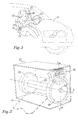
- Figure 1 shows a driver 10 of a vehicle 11, in this case a car; the driver is positioned on the driver side of the vehicle in front of the steering wheel 12 on a driver seat 13.
- the driver 10 is buckled using a belt 14 comprising a buckle 15.
- the belt 14 extends from a belt reel 20 according to an embodiment of the present invention, the belt reel being positioned on a pillar 25 of the vehicle.
- the pillar 25 is also referred to as the A-pillar 25 of the vehicle 11.
- the belt reel 20 can be positioned in other positions in the vehicle 11.
- the belt reel 20 forms a vehicle safety restraint arrangement together with the belt 14 and the buckle 15 after being assembled to the vehicle 11.
- FIG 2 shows an embodiment of the belt reel 20 comprising a belt 14 wound up about the belt reel 20.
- the belt 14 is transparently illustrated using dashed lines to better show the belt reel 20.
- the belt reel 20 permits the belt 14 to be extracted and retracted, e.g. to fasten a driver as shown in figure 1 .
- the belt reel 20 comprises a retraction mechanism in the form of a spring (not shown) which is loaded as the belt 14 is retracted. If a user, such as a driver, buckles up, the spring is loaded so as to retract the belt 14 after being unbuckled back to a position which generally is in the proximity of the belt reel 20.
- the belt reel 20 rotates about an axis of rotation A-A during the extraction or retraction of the belt 14.
- the belt reel 20 comprises a first and a second end 21, 22 and a belt section e23 extending between the first and the second end 21, 22.
- the belt section 23 is that part of the belt reel 20 about which the belt 14 is wound up about.
- a shaft 24 extends from the first and the second end 21, 22 of the belt reel 20.
- a housing 25 adapted to enclose the belt reel 20, while permitting the belt 14 to extend through a slot or opening (not shown in figure 2 ).
- the housing 25 is shown with portions partly transparent.
- the shafts 24 are rotationally attached to the housing 25, which in turn is attached to the vehicle 11, in figure 1 in the proximity of the A-pillar 25 of the vehicle 11.
- the belt reel 20 comprises a retraction mechanism, retraction means, to retract the belt 14 from an extracted position, e.g. when a driver unbuckles the belt 14 from the position shown in figure 1 .
- the retraction mechanism can be a spring which is pre tensioned, and loaded during the extraction of the belt 14 from the belt reel 20, other biasing members are possible, such as elastic polymer material, or an electric motor, or the like.
- the retraction mechanism can be configured to impart a torque to the belt reel of from 0,10-0,50 Nm, advantageously 0,10-0,3 Nm, preferably 0,12-0,25 Nm.
- a belt retraction brake 30 Arranged at the first end 21 of the belt reel 20 is a belt retraction brake 30. It should be noted that the belt reel 20 can be arranged with one or more belt retraction brakes, e.g. two belt retraction brakes as shown in figure 2 , however only one belt retraction brake 30 will be described herein.
- the retraction mechanism is adapted to impart a retraction force to the belt reel, however the retraction force imparted to the belt reel by the retraction mechanism is larger than the braking force imparted to the belt reel via the belt retraction brake.
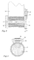
- Figure 3 shows a cross section of the belt reel 20 shown in figure 2 along the line I-I, the first and the second end 21, 22, the belt section 23, and the belt 14.
- the belt retraction brake 30 is arranged at the first end 21 of the belt reel 20, and arranged to be in working cooperation with the first end 21 of the belt reel 20.
- the belt retraction brake 30 is adapted to limit the speed of the belt 14 during retraction by reducing the angular velocity of the belt reel 20 during rotation, at least during the rotation which retracts the belt 14 back onto the belt reel 20.
- Figure 4 shows a cross section of the belt reel 20 shown in figure 3 and along the line II-II.
- Figure 4 shows the belt retraction brake 30 comprising a magnet portion 31, in the embodiment comprising a plurality of poles indicated by N, for the north pole, and S, for the south pole.
- the magnet portion 31 can be formed by a plurality of magnets.
- a drossel 32 comprising an iron core 33 and a copper wire 34 wrapped about a portion of the iron core 33 provides for the conductor. As the belt reel 20 rotates, eddy currents will be formed in the drossel 32 generating an electromagnetic force which imparts a braking force to the belt reel 20, which in turn will limit the retraction speed of the belt 14 during belt retraction.
- a belt retraction brake 30 during the retraction of the belt 14 is very advantageous, in practice; if the angular velocity of the belt reel 20 is increased the braking force of the belt retraction brake 30 will be significantly improved.
- FIG. 5 shows another embodiment of a belt reel 20.
- Figure 6 shows a cross section of the belt reel 20 shown in figure 5 along the line III-III.
- the belt reel 20 comprises a belt 14, a first and a second end 21, 22 with a belt section 23 arranged therebetween.
- the belt retraction brake 30 comprises in this case a circular copper ring 35 arranged about a magnet portion 31, in the form of a plurality of magnets, to create the braking force imparted to the belt reel 20, instead of a drossel as described above.
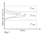
- Figure 7 shows a diagram comprising a first and a second graph A, B which represents the relation between the belt retraction brake 30 of the belt reel 20, described above using non limiting embodiments, and different types of damages which may occur during as a consequence of the retraction speed of the belt reel.
- the belt reel being positioned in a car as seen in figure 1 .
- the first axis is the highest spot speed (m/s) (highest speed at a point in time) and the second axis is the number of retractions (dimensionless).
- the diagram of figure 7 is further partitioned in three areas; the first area represents damage to pillars and doors, and primarily the A-pillar of the car; the second area represents a state at which no damage occurs, i.e. the belt is retracted without any damages or negative consequences and; the third area represents damage to the belt web, buckle, door seal, or the lacquer in the door area of the car.
- the first graph A shows the normal distribution for a normal belt reel having a standardized retraction mechanism.
- a percentage of the retractions inflict damage to the pillars or side panels of the car.
- Another percentage can inflict damage to the belt web, or door seal, due to being retracted to slow, i.e. the retraction mechanism is too weak.
- the normal distribution can be better fitted to the safe zone, i.e. the second area shown in figure 7 .
- the belt retraction brake permits the retraction mechanism to be stronger than what is otherwise suitable, while at the same time prevent the belt from acquiring an excessive speed during the retraction of the belt.
- the buckle 15 of the belt 14 can damage the interior panels of the car.
- the magnet portion 31 should thus be selected so that the retraction speed of the buckle is kept below 3.0 m/s, or preferably below 2.5 m/s.
- other parameters can be varied to limit the retraction speed.
- Suitable force of the magnets used in the magnet portion 31 are; 0,5-3 T, preferably about 0,75-2 T.
- Figures 8a-8b show a schematic embodiment of a magnetic break which can be used for the purpose of the invention.
- Figure 8a-8b show a disc shaped element in the form of a cupper disc 40 with an aperture 41.
- On opposite sides of the cupper disc are two button shaped permanent magnets 43, 44 arranged, totally four permanent magnets, with a radii of rmag a height of I mag and with a distance of t gap above resp. below the cupper disc 40.
- the permanent magnets are arranged as close together as possible, which determines the angle ⁇ in figure 8a .
- the permanent magnets 43, 44 have been magnetized with a remanence Br.
- a couple of the permanent magnets have a unidirected remanence, so that there are magnetic fields parallel with the rotation axis A-A of the cupper disc 40.
- the thickness t cu of the cupper disc can be between 0,5-5 mm, preferably 2,0-3,5 mm.
- the position radially of permanent magnet d off can be -1 to 3 mm, preferably 0,5-1,5 mm.
- the angular distance between the permanent magnets ⁇ can be 5-25 degrees, but as close as possible is advantageous.
- the magnets are positioned adjacent each other.
- the radii of permanent magnet r mag can be between 2-15 mm, 2-8 mm or advantageously 3-6 mm.
- the height of permanent magnet I mag can be 0,5-10 mm, 2-8 mm, advantageously 3-6 mm.
- the number of magnets on each side can be 1,2, 4, 6, 8, 10 or more, preferably 2-10 magnets on each side.
Landscapes
- Engineering & Computer Science (AREA)
- Mechanical Engineering (AREA)
- Storing, Repeated Paying-Out, And Re-Storing Of Elongated Articles (AREA)
- Emergency Lowering Means (AREA)
- Automotive Seat Belt Assembly (AREA)
Abstract
Description
- The present invention relates to a belt reel for a vehicle safety restraint arrangement, the belt reel is adapted to retract the belt from an extracted position using a retraction mechanism. The belt reel comprises a belt retraction brake adapted to limit the retraction speed during retraction of the belt. The present invention also relates to a method for limiting the retraction speed of a belt reel during retraction of a belt onto the belt reel.
- Seat belts, sometimes referred to as safety belts, in vehicles have significantly reduced the probability of injuries during collisions or other incidents. The belt itself is generally wounded up about a reel, generally referred to as a belt reel. A belt reel of conventional type comprises a retraction mechanism to retract the belt from an extracted position. One extracted position is a buckled position, e.g. the position a driver of the vehicle has when being position behind the steering wheel and buckled up.
- When the belt reel retracts the belt, the belt with its buckle runs the risk of either being retracted too slow or too fast. Is retracted too slow, the belt can be caught between the vehicle body and its door which might damage the belt. If the buckle is caught between the door and the vehicle body, the buckle could break or damage the lacquer of the vehicle body. Should the belt reel retract the belt too fast, the buckle runs the risk of smashing into the interior panels of the vehicle and damage the interior panel. It has been noticed that a belt retraction speed approximately >3.0 m/s can damage the interior panels of the vehicle if hit by the buckle. Even if the impact of the buckle on the interior panel does not destroy the interior panel, it leaves ugly marks which can reduce the value of the vehicle. Providing a controlled belt retraction is thus a problem which needs to be addressed.
- In the published UK patent application no.
GB 2,319,502 A - It is an object of the present invention to at least partly solve the above mentioned drawbacks, at least provide for an improvement, or at least provide for a useful alternative to existing solutions. The objective is at least partly met by a belt reel for a vehicle safety restraint arrangement. The belt reel comprises a retractable and extractable belt, a retraction mechanism adapted to retract the belt from an extracted position, and a belt retraction brake adapted to limit the retraction speed of the belt by imparting a braking force to the belt reel during retraction of the belt. The braking force of the belt retraction brake is imparted to the belt reel via inductance.
- The belt reel can be configured to have a retraction mechanism which can be adapted to retract the belt using a higher load than what would otherwise be suitable as during the retraction of the belt, the retraction speed of the belt can thus be kept from peaking. If the retraction mechanism is a pre tensioned biasing member, such as a pre tensioned spring, the belt retraction brake also compensates for tolerances of the pre tensioned spring of the belt reel.
- Furthermore, by using a retraction mechanism which retracts the belt using a higher load than what would otherwise be suitable, the risk of pinching the belt and possibly a belt buckle between a vehicle body and a door is reduced.
- The belt retraction brake can be passive, passive in terms of that it requires no electricity to operate, i.e. no power source. Permanent magnets are advantageously used when the belt retraction brake is passive. In another embodiment it is conceivable that a power source is connected together with an electronic control unit (ECU), to better control the retraction brake properties of the belt reel.
- According to an aspect, belt retraction brake comprises a coil portion adapted to cooperate with the belt reel, and at least one magnet arranged on the belt reel. The inductance is thus imparted during the retraction of the belt and as the belt reel rotates. A permanent magnet is advantageously used.
- According to an aspect, the coil portion of the belt retraction brake comprises a drossel, or optionally a copper cylinder.
- According to an aspect, the belt reel can comprise a first and a second end and a belt portion arranged between the first and the second end of the belt reel. The belt can thus be wound up about the belt portion, at least after retraction of the belt. At least one end of the belt reel is adapted to form a part of the belt retraction brake, optionally both the first and the second end of the belt reel is adapted to form a part of the belt retraction brake.
- The first and/or the second end of the belt reel can have different shapes and forms. For example, the first and/or the second end of the belt reel can be; symmetric or non symmetric; have a polygonal form such as triangular (or trigon), quadrilateral (or quadrangle or tetragon), pentagon, hexagon, heptagon, octagon, enneagon or nonagon, decagon. It should be noted that from decagon and above, the periphery can be considered more or less circular. Advantageously, the first and the second end comprise a substantially circular periphery, optionally a true circular periphery. It is possible that at least one end of the first and the second end of the belt reel comprises a non circular periphery.
- The drossel, or copper cylinder, can be arranged in the proximity of the first and/or the second end of the belt reel.
- According to an aspect, at least one magnet is arranged on the first and/or second end of the belt reel. The magnet can be a permanent magnet. At least 1, 2, 3, 4, 5, 6, 7, 8, 9, 10 or more magnets can be arranged on the first and/or second end of the belt reel. A suitable number of magnets are between 6-20 magnets. The at least one magnet is advantageously arranged about the periphery of the first and/or second end of the belt reel.
- According to an aspect, the braking force of the belt retraction brake is about 1-30 W.
- According to an aspect, the belt retraction brake comprises a disc shaped element, such as a cupper disc, aluminium disc, or a disc a conductive material, and at least one permanent magnet. The disc shaped element can be arranged on the belt reel, and preferably on the first and/or second end of the belt reel. The at least one permanent magnet can be arranged on a fixed position with respect to the disc shaped element, such as a belt reel housing.
- According to an aspect, the retraction mechanism is adapted to impart a retraction force to the belt reel. The retraction force is rotating the belt reel so that the belt is retracted from an extracted position. The retraction force imparted to the belt reel by the retraction mechanism is larger than the braking force imparted to the belt reel via the belt retraction brake.
- According to a second aspect, the present invention also relates to a method for limiting the retraction speed of a belt arranged on a belt reel. The belt reel is adapted for a vehicle safety restraint arrangement, the method comprising the steps of;
- retracting the belt onto a belt reel using a retraction mechanism;
- limiting the maximum speed during the retraction by imparting a braking force to the belt reel using induction.
- The belt reel can be a belt reel according to any of the appended claims.
- The present invention relates to a belt reel for a vehicle safety restraint arrangement. The belt reel comprises a retractable and extractable belt, a retraction mechanism adapted to retract the belt from an extracted position, a belt retraction brake adapted to limit the retraction speed of the belt by imparting a braking force to the belt reel during retraction of the belt. The braking force of the belt retraction brake is imparted to the belt reel via inductance. The present invention also relates to a method for limiting the retraction speed arranged on a belt reel. The present invention provides for a belt reel which reduces the risk for damage to the interior panel, lacquer or the vehicle body and/or door, and the belt itself.
- Non limiting embodiment of the present invention will be described in greater details with reference to the following figures in which;
-
figure 1 shows a driver of a car, the driver being buckled up using a belt, buckle and a belt reel according to an embodiment of the present invention; -
figure 2 shows the belt reel offigure 1 in greater detail; -
figure 3 shows the belt reel offigure 3 in a cross section; -
figure 4 shows the belt reel offigure 3 in a cross section; -
figure 5 shows a belt reel according to the present invention in a cross section having an alternative belt retraction brake; -
figure 6 shows the belt reel offigure 5 in a cross section; -
figure 7 shows a diagram of a the highest spot speed vs number for; a belt reel without induction brake and; a belt reel comprising induction brake and a strengthened retraction mechanism in the form of a strengthened spring and; -
figures 8a-8b show a schematic embodiment of a belt retraction brake in two different views. -
Figure 1 shows adriver 10 of avehicle 11, in this case a car; the driver is positioned on the driver side of the vehicle in front of thesteering wheel 12 on adriver seat 13. To prevent thedriver 10 from being injured in case of e.g. a collision, thedriver 10 is buckled using abelt 14 comprising abuckle 15. Thebelt 14 extends from abelt reel 20 according to an embodiment of the present invention, the belt reel being positioned on apillar 25 of the vehicle. Thepillar 25 is also referred to as the A-pillar 25 of thevehicle 11. It should be noted that thebelt reel 20 can be positioned in other positions in thevehicle 11. Thebelt reel 20 forms a vehicle safety restraint arrangement together with thebelt 14 and thebuckle 15 after being assembled to thevehicle 11. - Non limiting embodiments of the
belt reel 20 will hereafter be described in greater detail.Figure 2 shows an embodiment of thebelt reel 20 comprising abelt 14 wound up about thebelt reel 20. Thebelt 14 is transparently illustrated using dashed lines to better show thebelt reel 20. Thebelt reel 20 permits thebelt 14 to be extracted and retracted, e.g. to fasten a driver as shown infigure 1 . Thebelt reel 20 comprises a retraction mechanism in the form of a spring (not shown) which is loaded as thebelt 14 is retracted. If a user, such as a driver, buckles up, the spring is loaded so as to retract thebelt 14 after being unbuckled back to a position which generally is in the proximity of thebelt reel 20. Thebelt reel 20 rotates about an axis of rotation A-A during the extraction or retraction of thebelt 14. Thebelt reel 20 comprises a first and asecond end second end belt section 23 is that part of thebelt reel 20 about which thebelt 14 is wound up about. Ashaft 24 extends from the first and thesecond end belt reel 20. Further shown infigure 2 is ahousing 25, adapted to enclose thebelt reel 20, while permitting thebelt 14 to extend through a slot or opening (not shown infigure 2 ). For the sake of illustrating thebelt reel 20, thehousing 25 is shown with portions partly transparent. Theshafts 24 are rotationally attached to thehousing 25, which in turn is attached to thevehicle 11, infigure 1 in the proximity of the A-pillar 25 of thevehicle 11. - The
belt reel 20 comprises a retraction mechanism, retraction means, to retract thebelt 14 from an extracted position, e.g. when a driver unbuckles thebelt 14 from the position shown infigure 1 . The retraction mechanism can be a spring which is pre tensioned, and loaded during the extraction of thebelt 14 from thebelt reel 20, other biasing members are possible, such as elastic polymer material, or an electric motor, or the like. The retraction mechanism can be configured to impart a torque to the belt reel of from 0,10-0,50 Nm, advantageously 0,10-0,3 Nm, preferably 0,12-0,25 Nm. - Arranged at the
first end 21 of thebelt reel 20 is abelt retraction brake 30. It should be noted that thebelt reel 20 can be arranged with one or more belt retraction brakes, e.g. two belt retraction brakes as shown infigure 2 , however only onebelt retraction brake 30 will be described herein. The retraction mechanism is adapted to impart a retraction force to the belt reel, however the retraction force imparted to the belt reel by the retraction mechanism is larger than the braking force imparted to the belt reel via the belt retraction brake. -
Figure 3 shows a cross section of thebelt reel 20 shown infigure 2 along the line I-I, the first and thesecond end belt section 23, and thebelt 14. Thebelt retraction brake 30 is arranged at thefirst end 21 of thebelt reel 20, and arranged to be in working cooperation with thefirst end 21 of thebelt reel 20. Thebelt retraction brake 30 is adapted to limit the speed of thebelt 14 during retraction by reducing the angular velocity of thebelt reel 20 during rotation, at least during the rotation which retracts thebelt 14 back onto thebelt reel 20. -
Figure 4 shows a cross section of thebelt reel 20 shown infigure 3 and along the line II-II.Figure 4 shows thebelt retraction brake 30 comprising amagnet portion 31, in the embodiment comprising a plurality of poles indicated by N, for the north pole, and S, for the south pole. Themagnet portion 31 can be formed by a plurality of magnets. Adrossel 32 comprising aniron core 33 and acopper wire 34 wrapped about a portion of theiron core 33 provides for the conductor. As thebelt reel 20 rotates, eddy currents will be formed in thedrossel 32 generating an electromagnetic force which imparts a braking force to thebelt reel 20, which in turn will limit the retraction speed of thebelt 14 during belt retraction. - Some parameters which can be manipulated to increase the braking force imparted to the
belt reel 20 are: - Use stronger magnets - increases remanence T.
- Change fields faster (rotate the
belt reel 20 faster) - increases the frequency. - Use thicker materials of the conductive material, care have to be taken not to use to thick material as the distance between the magnets may be to far.
- Lower resistivity materials - decreases ρ.
- Using a
belt retraction brake 30 during the retraction of thebelt 14 is very advantageous, in practice; if the angular velocity of thebelt reel 20 is increased the braking force of thebelt retraction brake 30 will be significantly improved. -
Figure 5 shows another embodiment of abelt reel 20.Figure 6 shows a cross section of thebelt reel 20 shown infigure 5 along the line III-III. With reference tofigures 5 and 6 , thebelt reel 20 comprises abelt 14, a first and asecond end belt section 23 arranged therebetween. At thefirst end 21 of thebelt reel 20 is an alternativebelt retraction brake 30 arranged. Thebelt retraction brake 30 comprises in this case acircular copper ring 35 arranged about amagnet portion 31, in the form of a plurality of magnets, to create the braking force imparted to thebelt reel 20, instead of a drossel as described above. -
Figure 7 shows a diagram comprising a first and a second graph A, B which represents the relation between thebelt retraction brake 30 of thebelt reel 20, described above using non limiting embodiments, and different types of damages which may occur during as a consequence of the retraction speed of the belt reel. The belt reel being positioned in a car as seen infigure 1 . The first axis is the highest spot speed (m/s) (highest speed at a point in time) and the second axis is the number of retractions (dimensionless). - The diagram of
figure 7 is further partitioned in three areas;
the first area represents damage to pillars and doors, and primarily the A-pillar of the car; the second area represents a state at which no damage occurs, i.e. the belt is retracted without any damages or negative consequences and;
the third area represents damage to the belt web, buckle, door seal, or the lacquer in the door area of the car. - The first graph A shows the normal distribution for a normal belt reel having a standardized retraction mechanism. As can be seen in
figure 7 , using a normal belt reel without a belt retraction brake, a percentage of the retractions inflict damage to the pillars or side panels of the car. Another percentage can inflict damage to the belt web, or door seal, due to being retracted to slow, i.e. the retraction mechanism is too weak. - The damages mentioned above can be costly and renders ugly and unaesthetic marks on the interior of the car, or on the belt or its buckle. There is also a risk that the belt itself, sometimes referred to as the belt web, can be damaged, which can have dramatic consequences during a collision.
- Using a belt reel comprising a belt retraction brake, according to embodiments of the present invention, the normal distribution can be better fitted to the safe zone, i.e. the second area shown in
figure 7 . The belt retraction brake permits the retraction mechanism to be stronger than what is otherwise suitable, while at the same time prevent the belt from acquiring an excessive speed during the retraction of the belt. - It has been noticed that is the belt reaches a retraction speed of more than >3.0 m/s, the
buckle 15 of thebelt 14 can damage the interior panels of the car. Themagnet portion 31 should thus be selected so that the retraction speed of the buckle is kept below 3.0 m/s, or preferably below 2.5 m/s. Optionally, as mentioned above, other parameters can be varied to limit the retraction speed. - Suitable force of the magnets used in the
magnet portion 31 are; 0,5-3 T, preferably about 0,75-2 T. -
Figures 8a-8b show a schematic embodiment of a magnetic break which can be used for the purpose of the invention.Figure 8a-8b show a disc shaped element in the form of acupper disc 40 with an aperture 41. Thecupper disc 40 is connected to thebelt reel 20 and has the same axis of rotation A-A, as shown infigure 2 , and rotates with the rotation vectorω = ω A-A about the A-A axis. Total diameter is Dy. On opposite sides of the cupper disc are two button shapedpermanent magnets 43, 44 arranged, totally four permanent magnets, with a radii of rmag a height of Imag and with a distance of tgap above resp. below thecupper disc 40. The permanent magnets are arranged as close together as possible, which determines the angle Φ infigure 8a . Thepermanent magnets 43, 44 have been magnetized with a remanence Br. A couple of the permanent magnets have a unidirected remanence, so that there are magnetic fields parallel with the rotation axis A-A of thecupper disc 40. - The following references and values are used with respect to
figures 8a-8b .dy total diameter 70 mm dcu width of cupper disc 14 mm tcu thickness of cupper disc 2 mm σcu conductivity of cupper disc 5.998*107 S/m tgap air gap 1 mm rmag radii of permanent magnet 4 mm Imag height of permanent magnet 3 mm doff position radially of permanent magnet 1 mm φ angular distance between the permanent magnets As small as possible Br remanence of the permanent magnets 1 T nmag Number of magnets (on each side) 2 - Metals other than cupper could be used for the
cupper disc 40, such as aluminum for example. The thickness tcu of the cupper disc can be between 0,5-5 mm, preferably 2,0-3,5 mm. The position radially of permanent magnet doff can be -1 to 3 mm, preferably 0,5-1,5 mm. The angular distance between the permanent magnets Φ can be 5-25 degrees, but as close as possible is advantageous. Preferably the magnets are positioned adjacent each other. The radii of permanent magnet rmag can be between 2-15 mm, 2-8 mm or advantageously 3-6 mm. The height of permanent magnet Imag can be 0,5-10 mm, 2-8 mm, advantageously 3-6 mm. Optionally the number of magnets on each side can be 1,2, 4, 6, 8, 10 or more, preferably 2-10 magnets on each side.
Claims (15)
- A belt reel (20) for a vehicle safety restraint arrangement, said belt reel (20) comprising a retractable and extractable belt (14),
said belt reel (20) comprising a retraction mechanism adapted to retract said belt (14) from an extracted position,
characterized in that
said belt reel (20) further comprising a belt retraction brake (30) adapted to limit the retraction speed of said belt (14) by imparting a braking force to said belt reel (20) during retraction of said belt (14), said braking force of said belt retraction brake (30) being imparted to said belt reel (20) via inductance. - The belt reel according to claim 1, wherein said belt retraction brake (30) comprises a coil portion adapted to cooperate with said belt reel (20), and at least one magnet arranged on said belt reel (20).
- The belt reel according to claim 1 or 2, wherein said coil portion of said belt retraction brake (30) comprises a drossel (32).
- The belt reel according to claim 1 or 2, wherein said coil portion of said belt retraction brake (30) comprises a copper cylinder (35).
- The belt reel according to claim 1, wherein said belt retraction brake (30) comprises a disc shaped element, such as a cupper disc (40), and at least one permanent magnet (43, 44).
- The belt reel according to claim 5, wherein said disc shaped element is arranged on said belt reel (20).
- The belt reel according to any of the preceding claims, wherein said belt reel (20) comprises a first and a second end (21, 22), and a belt portion (23) arranged between said first and second end (21, 22), said belt (14) being wound up about said belt portion (23).
- The belt reel according to claim 7, wherein said first and/or said second end (21, 22) comprises a substantially circular periphery.
- The belt reel according to claim 7 or 8, wherein at least one magnet is arranged on said first and/or second end (21, 22) of said belt reel (20).
- The belt reel according to claim 9, wherein said at least one magnet is arranged about said substantially circular periphery of said first and/or second end (21, 22) of said belt reel (20).
- The belt reel according to any of the preceding claims, wherein said braking force of said belt retraction brake (30) is about 1-30 W.
- The belt reel according to any of the preceding claims, wherein said belt retraction brake (30) is a passive belt retraction brake.
- The belt reel according to any of the preceding claims, wherein said retraction mechanism is adapted to impart a retraction force to said belt reel (20), said retraction force imparted to said belt reel (20) by said retraction mechanism being larger than said braking force imparted to said belt reel (20) via said belt retraction brake (30).
- A method for limiting the retraction speed of a belt (14) arranged on a belt reel (20), the belt reel (20) being adapted for a vehicle safety restraint arrangement, said method comprising the steps of;- retracting the belt (14) onto a belt reel (20) using a retraction mechanism;- limiting the maximum speed during the retraction by imparting a braking force to the belt reel (20) using induction.
- The method according to claim 14, wherein said belt reel is a belt reel (20) according to any of claims 1-13.
Priority Applications (3)
| Application Number | Priority Date | Filing Date | Title |
|---|---|---|---|
| EP12175292.7A EP2682313B1 (en) | 2012-07-06 | 2012-07-06 | Belt reel for a vehicle safety restraint arrangement and method for limiting the retraction speed of a belt during retraction onto a belt reel |
| US13/935,245 US9862351B2 (en) | 2012-07-06 | 2013-07-03 | Belt reel for a vehicle safety restraint arrangement and method for limiting the retraction speed of a belt during retraction onto a belt reel |
| CN201310280773.5A CN103522978B (en) | 2012-07-06 | 2013-07-05 | Belt reel for a vehicle safety restraint arrangement and method for limiting the retraction speed of a belt during retraction onto a belt reel |
Applications Claiming Priority (1)
| Application Number | Priority Date | Filing Date | Title |
|---|---|---|---|
| EP12175292.7A EP2682313B1 (en) | 2012-07-06 | 2012-07-06 | Belt reel for a vehicle safety restraint arrangement and method for limiting the retraction speed of a belt during retraction onto a belt reel |
Publications (2)
| Publication Number | Publication Date |
|---|---|
| EP2682313A1 true EP2682313A1 (en) | 2014-01-08 |
| EP2682313B1 EP2682313B1 (en) | 2015-01-14 |
Family
ID=46465123
Family Applications (1)
| Application Number | Title | Priority Date | Filing Date |
|---|---|---|---|
| EP12175292.7A Not-in-force EP2682313B1 (en) | 2012-07-06 | 2012-07-06 | Belt reel for a vehicle safety restraint arrangement and method for limiting the retraction speed of a belt during retraction onto a belt reel |
Country Status (3)
| Country | Link |
|---|---|
| US (1) | US9862351B2 (en) |
| EP (1) | EP2682313B1 (en) |
| CN (1) | CN103522978B (en) |
Cited By (3)
| Publication number | Priority date | Publication date | Assignee | Title |
|---|---|---|---|---|
| DE102013217238A1 (en) * | 2013-08-29 | 2015-03-05 | Autoliv Development Ab | Belt retractor for a safety belt of a motor vehicle |
| CN107595354A (en) * | 2017-09-20 | 2018-01-19 | 范海盟 | A kind of otch protector of Implanted cardiac pacemaker |
| WO2023220953A1 (en) * | 2022-05-18 | 2023-11-23 | 浙江吉利控股集团有限公司 | Retractor, seat belt device, and apparatus |
Families Citing this family (4)
| Publication number | Priority date | Publication date | Assignee | Title |
|---|---|---|---|---|
| CN109263596B (en) * | 2015-03-12 | 2020-04-24 | 比亚迪股份有限公司 | Retractor and seat belt winding device |
| US10421429B2 (en) | 2017-08-17 | 2019-09-24 | Ford Global Technologies, Llc | Load-limiting seatbelt retractor |
| US10427640B2 (en) | 2017-09-25 | 2019-10-01 | Ford Global Technologies, Llc | Load-limiting seatbelt assembly |
| US12528440B2 (en) | 2023-10-30 | 2026-01-20 | GM Global Technology Operations LLC | Seatbelt system |
Citations (4)
| Publication number | Priority date | Publication date | Assignee | Title |
|---|---|---|---|---|
| GB2265541A (en) * | 1992-03-30 | 1993-10-06 | Takata Corp | Device for reducing the rotational speed of a seat belt take-up shaft |
| GB2319502A (en) | 1996-11-07 | 1998-05-27 | Alliedsignal Deutschland Gmbh | Electromagnetic seatbelt clamping. |
| US20070114318A1 (en) * | 2005-11-14 | 2007-05-24 | Thogersen Paul P | Magnetically actuated personnel restraint system |
| DE102008042020A1 (en) * | 2008-09-12 | 2010-03-18 | Robert Bosch Gmbh | Belt retractor unit for use in e.g. belt system, for passenger protection system in motor vehicle, has brake arrangement implemented as eddy current brake, which is coupled with spindle using adjustable magnetic field |
Family Cites Families (23)
| Publication number | Priority date | Publication date | Assignee | Title |
|---|---|---|---|---|
| US3787002A (en) * | 1970-10-20 | 1974-01-22 | Tokai Rika Co Ltd | Emergency locking device for safety seat belt used in motor vehicles and the like |
| DE2402748C2 (en) * | 1974-01-21 | 1986-07-03 | Artur 7060 Schorndorf Föhl | Device for initiating the reel shaft blocking of an automatic seat belt retractor |
| DE3116355A1 (en) * | 1981-04-24 | 1982-11-18 | Volkswagenwerk Ag, 3180 Wolfsburg | SAFETY DEVICE FOR VEHICLES, IN PARTICULAR MOTOR VEHICLES |
| US4729525A (en) * | 1986-12-12 | 1988-03-08 | Trw Vehicle Safety Systems Inc. | Seat belt retractor with electrically actuatable locking mechanism |
| US4771854A (en) * | 1987-10-07 | 1988-09-20 | General Motors Corporation | Belt winding brake for passive belt retractor |
| US5224736A (en) * | 1989-02-10 | 1993-07-06 | Autoflug Gmbh & Co. | Safety belt arrangement for occupants of land vehicles and aircraft |
| US5441304A (en) * | 1993-06-01 | 1995-08-15 | Takata Inc. | Seat belt retractor activation mechanism responsive to anti-lock braking systems |
| US6257363B1 (en) * | 1997-12-16 | 2001-07-10 | Nsk Ltd. | Automotive passenger restraint and protection apparatus |
| JP4667549B2 (en) * | 1999-09-10 | 2011-04-13 | オートリブ株式会社 | Seat belt device |
| JP4811893B2 (en) * | 2000-04-21 | 2011-11-09 | タカタ株式会社 | Motorized seat belt retractor |
| US6805381B2 (en) * | 2001-02-20 | 2004-10-19 | Delphi Technologies, Inc. | Magnetorheological seat belt actuator |
| DE10122048A1 (en) * | 2001-05-07 | 2002-11-21 | Takata Petri Gmbh Ulm | Method for restraining a vehicle occupant |
| US6685124B2 (en) * | 2001-11-30 | 2004-02-03 | Trw Vehicle Safety Systems Inc. | Seat belt pretensioner with brake |
| DE10322036A1 (en) | 2003-05-16 | 2004-12-02 | Adam Opel Ag | Safety belt reeling arrangement has braking system for reducing reeling rate with increasing diameter of belt roll that only brakes retraction rate if belt retracted to more than 2/3 of total length |
| US6863236B2 (en) * | 2003-07-25 | 2005-03-08 | Key Safety Systems, Inc. | Electromagnetic seatbelt energy management devices |
| DE102004053305A1 (en) | 2004-11-04 | 2006-06-01 | Trw Automotive Gmbh | Belt retractor for a vehicle seat belt system and vehicle seat belt system |
| DE102005011904B4 (en) * | 2005-03-15 | 2020-04-16 | Trw Automotive Gmbh | Belt retractor for a seat belt |
| DE102005016825A1 (en) * | 2005-04-12 | 2006-10-19 | Trw Automotive Gmbh | Safety device for a vehicle occupant restraint system |
| DE102005041098A1 (en) * | 2005-08-30 | 2007-03-08 | Siemens Ag | retractor |
| JP2007176423A (en) * | 2005-12-28 | 2007-07-12 | Takata Corp | Seat belt retractor, seat belt device, and vehicle having seat belt device |
| DE102006037735B4 (en) | 2006-08-11 | 2020-07-30 | Trw Automotive Gmbh | Belt retractor for a seat belt system |
| US8262133B2 (en) * | 2008-04-23 | 2012-09-11 | GM Global Technology Operations LLC | Belt retractor utilizing active material actuation |
| US8418819B2 (en) * | 2008-08-22 | 2013-04-16 | Inventus Engineering Gmbh | Movement damping apparatus |
-
2012
- 2012-07-06 EP EP12175292.7A patent/EP2682313B1/en not_active Not-in-force
-
2013
- 2013-07-03 US US13/935,245 patent/US9862351B2/en not_active Expired - Fee Related
- 2013-07-05 CN CN201310280773.5A patent/CN103522978B/en active Active
Patent Citations (4)
| Publication number | Priority date | Publication date | Assignee | Title |
|---|---|---|---|---|
| GB2265541A (en) * | 1992-03-30 | 1993-10-06 | Takata Corp | Device for reducing the rotational speed of a seat belt take-up shaft |
| GB2319502A (en) | 1996-11-07 | 1998-05-27 | Alliedsignal Deutschland Gmbh | Electromagnetic seatbelt clamping. |
| US20070114318A1 (en) * | 2005-11-14 | 2007-05-24 | Thogersen Paul P | Magnetically actuated personnel restraint system |
| DE102008042020A1 (en) * | 2008-09-12 | 2010-03-18 | Robert Bosch Gmbh | Belt retractor unit for use in e.g. belt system, for passenger protection system in motor vehicle, has brake arrangement implemented as eddy current brake, which is coupled with spindle using adjustable magnetic field |
Cited By (4)
| Publication number | Priority date | Publication date | Assignee | Title |
|---|---|---|---|---|
| DE102013217238A1 (en) * | 2013-08-29 | 2015-03-05 | Autoliv Development Ab | Belt retractor for a safety belt of a motor vehicle |
| DE102013217238B4 (en) * | 2013-08-29 | 2021-03-04 | Autoliv Development Ab | Belt retractor for a safety belt of a motor vehicle |
| CN107595354A (en) * | 2017-09-20 | 2018-01-19 | 范海盟 | A kind of otch protector of Implanted cardiac pacemaker |
| WO2023220953A1 (en) * | 2022-05-18 | 2023-11-23 | 浙江吉利控股集团有限公司 | Retractor, seat belt device, and apparatus |
Also Published As
| Publication number | Publication date |
|---|---|
| CN103522978A (en) | 2014-01-22 |
| EP2682313B1 (en) | 2015-01-14 |
| US9862351B2 (en) | 2018-01-09 |
| CN103522978B (en) | 2017-05-10 |
| US20140008478A1 (en) | 2014-01-09 |
Similar Documents
| Publication | Publication Date | Title |
|---|---|---|
| EP2682313B1 (en) | Belt reel for a vehicle safety restraint arrangement and method for limiting the retraction speed of a belt during retraction onto a belt reel | |
| EP3075061B1 (en) | Sensor arrangement and use of the sensor arrangement in a motor vehicle control device | |
| EP3446396B1 (en) | Electric disc rotor machine | |
| EP2768692B1 (en) | Secondary coil for installation on a vehicle with electric drivetrain and vehicle with electric drivetrain | |
| JP2013091446A (en) | Through anchor and seatbelt device | |
| DE102018119789A1 (en) | Load-limiting safety belt retractor | |
| EP2613961B1 (en) | Device for contactless transmission of energy to a vehicle, vehicle and use of a rim of a vehicle | |
| DE102017205855B3 (en) | motor vehicle | |
| DE845904C (en) | Device for vehicles equipped with a differential | |
| CN202990633U (en) | Automatic locking and unlocking device for electric automobile door | |
| CN212890229U (en) | Self-adaptation limit for strength type safety belt coiler and safety belt subassembly based on magnetic control | |
| WO2013156168A2 (en) | Coil unit and device for the inductive transfer of electrical energy | |
| DE102009014687B4 (en) | Occupant protection device for a motor vehicle | |
| CN205905942U (en) | Car blet pressure relief device | |
| DE102011089645A1 (en) | Switching arrangement for a buckle | |
| CN108189798B (en) | Automobile safety belt system | |
| JP7166864B2 (en) | vehicle seat belt device | |
| DE102017206928A1 (en) | Electric machine comprising a stator and a rotor and rotor for an electric machine | |
| US20160276879A1 (en) | Nanoscale Magnet Composite for High-Performance Permanent Magnets | |
| CN2728853Y (en) | Automobile magnetic anti-collision device | |
| CN104260685A (en) | Passenger safety device for car | |
| DE102013018277A1 (en) | Electric machine | |
| US20250379480A1 (en) | Elevator system, permanent magnet motor therefor, and manufacturing method for permanent magnet motor | |
| CN206781688U (en) | A kind of shield device of tyre for preventing nail thorn metal object and puncturing tire | |
| CN203567683U (en) | Automobile safety belt winding device |
Legal Events
| Date | Code | Title | Description |
|---|---|---|---|
| PUAI | Public reference made under article 153(3) epc to a published international application that has entered the european phase |
Free format text: ORIGINAL CODE: 0009012 |
|
| AK | Designated contracting states |
Kind code of ref document: A1 Designated state(s): AL AT BE BG CH CY CZ DE DK EE ES FI FR GB GR HR HU IE IS IT LI LT LU LV MC MK MT NL NO PL PT RO RS SE SI SK SM TR |
|
| AX | Request for extension of the european patent |
Extension state: BA ME |
|
| 17P | Request for examination filed |
Effective date: 20140708 |
|
| RBV | Designated contracting states (corrected) |
Designated state(s): AL AT BE BG CH CY CZ DE DK EE ES FI FR GB GR HR HU IE IS IT LI LT LU LV MC MK MT NL NO PL PT RO RS SE SI SK SM TR |
|
| GRAP | Despatch of communication of intention to grant a patent |
Free format text: ORIGINAL CODE: EPIDOSNIGR1 |
|
| RIC1 | Information provided on ipc code assigned before grant |
Ipc: B60R 22/34 20060101AFI20140730BHEP |
|
| INTG | Intention to grant announced |
Effective date: 20140903 |
|
| GRAS | Grant fee paid |
Free format text: ORIGINAL CODE: EPIDOSNIGR3 |
|
| GRAA | (expected) grant |
Free format text: ORIGINAL CODE: 0009210 |
|
| AK | Designated contracting states |
Kind code of ref document: B1 Designated state(s): AL AT BE BG CH CY CZ DE DK EE ES FI FR GB GR HR HU IE IS IT LI LT LU LV MC MK MT NL NO PL PT RO RS SE SI SK SM TR |
|
| REG | Reference to a national code |
Ref country code: GB Ref legal event code: FG4D |
|
| REG | Reference to a national code |
Ref country code: CH Ref legal event code: EP |
|
| REG | Reference to a national code |
Ref country code: IE Ref legal event code: FG4D |
|
| REG | Reference to a national code |
Ref country code: AT Ref legal event code: REF Ref document number: 706850 Country of ref document: AT Kind code of ref document: T Effective date: 20150215 |
|
| REG | Reference to a national code |
Ref country code: DE Ref legal event code: R096 Ref document number: 602012004885 Country of ref document: DE Effective date: 20150226 |
|
| REG | Reference to a national code |
Ref country code: SE Ref legal event code: TRGR |
|
| REG | Reference to a national code |
Ref country code: NL Ref legal event code: VDEP Effective date: 20150114 |
|
| REG | Reference to a national code |
Ref country code: AT Ref legal event code: MK05 Ref document number: 706850 Country of ref document: AT Kind code of ref document: T Effective date: 20150114 |
|
| REG | Reference to a national code |
Ref country code: LT Ref legal event code: MG4D |
|
| PG25 | Lapsed in a contracting state [announced via postgrant information from national office to epo] |
Ref country code: LT Free format text: LAPSE BECAUSE OF FAILURE TO SUBMIT A TRANSLATION OF THE DESCRIPTION OR TO PAY THE FEE WITHIN THE PRESCRIBED TIME-LIMIT Effective date: 20150114 Ref country code: NO Free format text: LAPSE BECAUSE OF FAILURE TO SUBMIT A TRANSLATION OF THE DESCRIPTION OR TO PAY THE FEE WITHIN THE PRESCRIBED TIME-LIMIT Effective date: 20150414 Ref country code: HR Free format text: LAPSE BECAUSE OF FAILURE TO SUBMIT A TRANSLATION OF THE DESCRIPTION OR TO PAY THE FEE WITHIN THE PRESCRIBED TIME-LIMIT Effective date: 20150114 Ref country code: ES Free format text: LAPSE BECAUSE OF FAILURE TO SUBMIT A TRANSLATION OF THE DESCRIPTION OR TO PAY THE FEE WITHIN THE PRESCRIBED TIME-LIMIT Effective date: 20150114 Ref country code: FI Free format text: LAPSE BECAUSE OF FAILURE TO SUBMIT A TRANSLATION OF THE DESCRIPTION OR TO PAY THE FEE WITHIN THE PRESCRIBED TIME-LIMIT Effective date: 20150114 Ref country code: BG Free format text: LAPSE BECAUSE OF FAILURE TO SUBMIT A TRANSLATION OF THE DESCRIPTION OR TO PAY THE FEE WITHIN THE PRESCRIBED TIME-LIMIT Effective date: 20150414 |
|
| PG25 | Lapsed in a contracting state [announced via postgrant information from national office to epo] |
Ref country code: IS Free format text: LAPSE BECAUSE OF FAILURE TO SUBMIT A TRANSLATION OF THE DESCRIPTION OR TO PAY THE FEE WITHIN THE PRESCRIBED TIME-LIMIT Effective date: 20150514 Ref country code: AT Free format text: LAPSE BECAUSE OF FAILURE TO SUBMIT A TRANSLATION OF THE DESCRIPTION OR TO PAY THE FEE WITHIN THE PRESCRIBED TIME-LIMIT Effective date: 20150114 Ref country code: PL Free format text: LAPSE BECAUSE OF FAILURE TO SUBMIT A TRANSLATION OF THE DESCRIPTION OR TO PAY THE FEE WITHIN THE PRESCRIBED TIME-LIMIT Effective date: 20150114 Ref country code: RS Free format text: LAPSE BECAUSE OF FAILURE TO SUBMIT A TRANSLATION OF THE DESCRIPTION OR TO PAY THE FEE WITHIN THE PRESCRIBED TIME-LIMIT Effective date: 20150114 Ref country code: LV Free format text: LAPSE BECAUSE OF FAILURE TO SUBMIT A TRANSLATION OF THE DESCRIPTION OR TO PAY THE FEE WITHIN THE PRESCRIBED TIME-LIMIT Effective date: 20150114 Ref country code: NL Free format text: LAPSE BECAUSE OF FAILURE TO SUBMIT A TRANSLATION OF THE DESCRIPTION OR TO PAY THE FEE WITHIN THE PRESCRIBED TIME-LIMIT Effective date: 20150114 Ref country code: GR Free format text: LAPSE BECAUSE OF FAILURE TO SUBMIT A TRANSLATION OF THE DESCRIPTION OR TO PAY THE FEE WITHIN THE PRESCRIBED TIME-LIMIT Effective date: 20150415 |
|
| REG | Reference to a national code |
Ref country code: DE Ref legal event code: R097 Ref document number: 602012004885 Country of ref document: DE |
|
| PG25 | Lapsed in a contracting state [announced via postgrant information from national office to epo] |
Ref country code: DK Free format text: LAPSE BECAUSE OF FAILURE TO SUBMIT A TRANSLATION OF THE DESCRIPTION OR TO PAY THE FEE WITHIN THE PRESCRIBED TIME-LIMIT Effective date: 20150114 Ref country code: RO Free format text: LAPSE BECAUSE OF FAILURE TO SUBMIT A TRANSLATION OF THE DESCRIPTION OR TO PAY THE FEE WITHIN THE PRESCRIBED TIME-LIMIT Effective date: 20150114 Ref country code: SK Free format text: LAPSE BECAUSE OF FAILURE TO SUBMIT A TRANSLATION OF THE DESCRIPTION OR TO PAY THE FEE WITHIN THE PRESCRIBED TIME-LIMIT Effective date: 20150114 Ref country code: CZ Free format text: LAPSE BECAUSE OF FAILURE TO SUBMIT A TRANSLATION OF THE DESCRIPTION OR TO PAY THE FEE WITHIN THE PRESCRIBED TIME-LIMIT Effective date: 20150114 Ref country code: EE Free format text: LAPSE BECAUSE OF FAILURE TO SUBMIT A TRANSLATION OF THE DESCRIPTION OR TO PAY THE FEE WITHIN THE PRESCRIBED TIME-LIMIT Effective date: 20150114 |
|
| PLBE | No opposition filed within time limit |
Free format text: ORIGINAL CODE: 0009261 |
|
| STAA | Information on the status of an ep patent application or granted ep patent |
Free format text: STATUS: NO OPPOSITION FILED WITHIN TIME LIMIT |
|
| 26N | No opposition filed |
Effective date: 20151015 |
|
| PG25 | Lapsed in a contracting state [announced via postgrant information from national office to epo] |
Ref country code: IT Free format text: LAPSE BECAUSE OF FAILURE TO SUBMIT A TRANSLATION OF THE DESCRIPTION OR TO PAY THE FEE WITHIN THE PRESCRIBED TIME-LIMIT Effective date: 20150114 |
|
| PG25 | Lapsed in a contracting state [announced via postgrant information from national office to epo] |
Ref country code: SI Free format text: LAPSE BECAUSE OF FAILURE TO SUBMIT A TRANSLATION OF THE DESCRIPTION OR TO PAY THE FEE WITHIN THE PRESCRIBED TIME-LIMIT Effective date: 20150114 Ref country code: MC Free format text: LAPSE BECAUSE OF FAILURE TO SUBMIT A TRANSLATION OF THE DESCRIPTION OR TO PAY THE FEE WITHIN THE PRESCRIBED TIME-LIMIT Effective date: 20150114 |
|
| REG | Reference to a national code |
Ref country code: CH Ref legal event code: PL |
|
| PG25 | Lapsed in a contracting state [announced via postgrant information from national office to epo] |
Ref country code: LU Free format text: LAPSE BECAUSE OF FAILURE TO SUBMIT A TRANSLATION OF THE DESCRIPTION OR TO PAY THE FEE WITHIN THE PRESCRIBED TIME-LIMIT Effective date: 20150706 |
|
| REG | Reference to a national code |
Ref country code: IE Ref legal event code: MM4A |
|
| PG25 | Lapsed in a contracting state [announced via postgrant information from national office to epo] |
Ref country code: CH Free format text: LAPSE BECAUSE OF NON-PAYMENT OF DUE FEES Effective date: 20150731 Ref country code: LI Free format text: LAPSE BECAUSE OF NON-PAYMENT OF DUE FEES Effective date: 20150731 |
|
| REG | Reference to a national code |
Ref country code: FR Ref legal event code: ST Effective date: 20160331 |
|
| PG25 | Lapsed in a contracting state [announced via postgrant information from national office to epo] |
Ref country code: BE Free format text: LAPSE BECAUSE OF FAILURE TO SUBMIT A TRANSLATION OF THE DESCRIPTION OR TO PAY THE FEE WITHIN THE PRESCRIBED TIME-LIMIT Effective date: 20150114 Ref country code: FR Free format text: LAPSE BECAUSE OF NON-PAYMENT OF DUE FEES Effective date: 20150731 |
|
| PG25 | Lapsed in a contracting state [announced via postgrant information from national office to epo] |
Ref country code: IE Free format text: LAPSE BECAUSE OF NON-PAYMENT OF DUE FEES Effective date: 20150706 |
|
| PG25 | Lapsed in a contracting state [announced via postgrant information from national office to epo] |
Ref country code: MT Free format text: LAPSE BECAUSE OF FAILURE TO SUBMIT A TRANSLATION OF THE DESCRIPTION OR TO PAY THE FEE WITHIN THE PRESCRIBED TIME-LIMIT Effective date: 20150114 |
|
| PG25 | Lapsed in a contracting state [announced via postgrant information from national office to epo] |
Ref country code: HU Free format text: LAPSE BECAUSE OF FAILURE TO SUBMIT A TRANSLATION OF THE DESCRIPTION OR TO PAY THE FEE WITHIN THE PRESCRIBED TIME-LIMIT; INVALID AB INITIO Effective date: 20120706 Ref country code: SM Free format text: LAPSE BECAUSE OF FAILURE TO SUBMIT A TRANSLATION OF THE DESCRIPTION OR TO PAY THE FEE WITHIN THE PRESCRIBED TIME-LIMIT Effective date: 20150114 |
|
| PG25 | Lapsed in a contracting state [announced via postgrant information from national office to epo] |
Ref country code: CY Free format text: LAPSE BECAUSE OF FAILURE TO SUBMIT A TRANSLATION OF THE DESCRIPTION OR TO PAY THE FEE WITHIN THE PRESCRIBED TIME-LIMIT Effective date: 20150114 |
|
| PG25 | Lapsed in a contracting state [announced via postgrant information from national office to epo] |
Ref country code: MK Free format text: LAPSE BECAUSE OF FAILURE TO SUBMIT A TRANSLATION OF THE DESCRIPTION OR TO PAY THE FEE WITHIN THE PRESCRIBED TIME-LIMIT Effective date: 20150114 Ref country code: TR Free format text: LAPSE BECAUSE OF FAILURE TO SUBMIT A TRANSLATION OF THE DESCRIPTION OR TO PAY THE FEE WITHIN THE PRESCRIBED TIME-LIMIT Effective date: 20150114 Ref country code: PT Free format text: LAPSE BECAUSE OF FAILURE TO SUBMIT A TRANSLATION OF THE DESCRIPTION OR TO PAY THE FEE WITHIN THE PRESCRIBED TIME-LIMIT Effective date: 20150114 |
|
| PG25 | Lapsed in a contracting state [announced via postgrant information from national office to epo] |
Ref country code: AL Free format text: LAPSE BECAUSE OF FAILURE TO SUBMIT A TRANSLATION OF THE DESCRIPTION OR TO PAY THE FEE WITHIN THE PRESCRIBED TIME-LIMIT Effective date: 20150114 |
|
| PGFP | Annual fee paid to national office [announced via postgrant information from national office to epo] |
Ref country code: SE Payment date: 20190718 Year of fee payment: 8 |
|
| PGFP | Annual fee paid to national office [announced via postgrant information from national office to epo] |
Ref country code: GB Payment date: 20190710 Year of fee payment: 8 |
|
| REG | Reference to a national code |
Ref country code: SE Ref legal event code: EUG |
|
| GBPC | Gb: european patent ceased through non-payment of renewal fee |
Effective date: 20200706 |
|
| PG25 | Lapsed in a contracting state [announced via postgrant information from national office to epo] |
Ref country code: GB Free format text: LAPSE BECAUSE OF NON-PAYMENT OF DUE FEES Effective date: 20200706 |
|
| PG25 | Lapsed in a contracting state [announced via postgrant information from national office to epo] |
Ref country code: SE Free format text: LAPSE BECAUSE OF NON-PAYMENT OF DUE FEES Effective date: 20200707 |
|
| PGFP | Annual fee paid to national office [announced via postgrant information from national office to epo] |
Ref country code: DE Payment date: 20240619 Year of fee payment: 13 |
|
| REG | Reference to a national code |
Ref country code: DE Ref legal event code: R119 Ref document number: 602012004885 Country of ref document: DE |
|
| PG25 | Lapsed in a contracting state [announced via postgrant information from national office to epo] |
Ref country code: DE Free format text: LAPSE BECAUSE OF NON-PAYMENT OF DUE FEES Effective date: 20260203 |