EP2682207B1 - Vibration isolator assembly - Google Patents
Vibration isolator assembly Download PDFInfo
- Publication number
- EP2682207B1 EP2682207B1 EP13173121.8A EP13173121A EP2682207B1 EP 2682207 B1 EP2682207 B1 EP 2682207B1 EP 13173121 A EP13173121 A EP 13173121A EP 2682207 B1 EP2682207 B1 EP 2682207B1
- Authority
- EP
- European Patent Office
- Prior art keywords
- bellows
- assembly
- piston
- coupled
- end plate
- Prior art date
- Legal status (The legal status is an assumption and is not a legal conclusion. Google has not performed a legal analysis and makes no representation as to the accuracy of the status listed.)
- Active
Links
- 238000004519 manufacturing process Methods 0.000 claims description 77
- 238000000034 method Methods 0.000 claims description 58
- 239000000654 additive Substances 0.000 claims description 23
- 230000000996 additive effect Effects 0.000 claims description 23
- 239000012530 fluid Substances 0.000 claims description 10
- 230000006378 damage Effects 0.000 claims description 2
- 239000000463 material Substances 0.000 description 30
- 238000000429 assembly Methods 0.000 description 20
- 230000000712 assembly Effects 0.000 description 20
- 238000013461 design Methods 0.000 description 17
- 239000000843 powder Substances 0.000 description 15
- 238000005516 engineering process Methods 0.000 description 9
- 230000008569 process Effects 0.000 description 9
- PXHVJJICTQNCMI-UHFFFAOYSA-N Nickel Chemical compound [Ni] PXHVJJICTQNCMI-UHFFFAOYSA-N 0.000 description 8
- 229910052751 metal Inorganic materials 0.000 description 8
- 239000002184 metal Substances 0.000 description 8
- 239000000956 alloy Substances 0.000 description 6
- 238000005538 encapsulation Methods 0.000 description 6
- 229910000601 superalloy Inorganic materials 0.000 description 6
- 230000006870 function Effects 0.000 description 5
- 238000013459 approach Methods 0.000 description 4
- 238000001513 hot isostatic pressing Methods 0.000 description 4
- 238000002844 melting Methods 0.000 description 4
- 230000008018 melting Effects 0.000 description 4
- 229910052759 nickel Inorganic materials 0.000 description 4
- RTAQQCXQSZGOHL-UHFFFAOYSA-N Titanium Chemical compound [Ti] RTAQQCXQSZGOHL-UHFFFAOYSA-N 0.000 description 3
- 229910045601 alloy Inorganic materials 0.000 description 3
- 238000000149 argon plasma sintering Methods 0.000 description 3
- 238000000151 deposition Methods 0.000 description 3
- 238000009826 distribution Methods 0.000 description 3
- 238000012545 processing Methods 0.000 description 3
- 239000010936 titanium Substances 0.000 description 3
- OQPDWFJSZHWILH-UHFFFAOYSA-N [Al].[Al].[Al].[Ti] Chemical compound [Al].[Al].[Al].[Ti] OQPDWFJSZHWILH-UHFFFAOYSA-N 0.000 description 2
- 230000015572 biosynthetic process Effects 0.000 description 2
- 238000000576 coating method Methods 0.000 description 2
- 238000011960 computer-aided design Methods 0.000 description 2
- 230000008021 deposition Effects 0.000 description 2
- 238000010894 electron beam technology Methods 0.000 description 2
- 230000004927 fusion Effects 0.000 description 2
- 239000012255 powdered metal Substances 0.000 description 2
- 238000007789 sealing Methods 0.000 description 2
- 239000007787 solid Substances 0.000 description 2
- 230000035882 stress Effects 0.000 description 2
- 229910052719 titanium Inorganic materials 0.000 description 2
- 229910021324 titanium aluminide Inorganic materials 0.000 description 2
- 238000011282 treatment Methods 0.000 description 2
- 238000003466 welding Methods 0.000 description 2
- 229910000838 Al alloy Inorganic materials 0.000 description 1
- 229910001069 Ti alloy Inorganic materials 0.000 description 1
- 230000032683 aging Effects 0.000 description 1
- 229910052782 aluminium Inorganic materials 0.000 description 1
- XAGFODPZIPBFFR-UHFFFAOYSA-N aluminium Chemical compound [Al] XAGFODPZIPBFFR-UHFFFAOYSA-N 0.000 description 1
- 238000000137 annealing Methods 0.000 description 1
- 230000009286 beneficial effect Effects 0.000 description 1
- WHRVRSCEWKLAHX-LQDWTQKMSA-N benzylpenicillin procaine Chemical compound [H+].CCN(CC)CCOC(=O)C1=CC=C(N)C=C1.N([C@H]1[C@H]2SC([C@@H](N2C1=O)C([O-])=O)(C)C)C(=O)CC1=CC=CC=C1 WHRVRSCEWKLAHX-LQDWTQKMSA-N 0.000 description 1
- 238000005266 casting Methods 0.000 description 1
- 229910017052 cobalt Inorganic materials 0.000 description 1
- 239000010941 cobalt Substances 0.000 description 1
- GUTLYIVDDKVIGB-UHFFFAOYSA-N cobalt atom Chemical compound [Co] GUTLYIVDDKVIGB-UHFFFAOYSA-N 0.000 description 1
- 230000008602 contraction Effects 0.000 description 1
- 230000008878 coupling Effects 0.000 description 1
- 238000010168 coupling process Methods 0.000 description 1
- 238000005859 coupling reaction Methods 0.000 description 1
- 238000005336 cracking Methods 0.000 description 1
- 239000013078 crystal Substances 0.000 description 1
- 230000007547 defect Effects 0.000 description 1
- 230000007123 defense Effects 0.000 description 1
- 230000007812 deficiency Effects 0.000 description 1
- 238000010586 diagram Methods 0.000 description 1
- 239000000428 dust Substances 0.000 description 1
- 230000007613 environmental effect Effects 0.000 description 1
- RLQJEEJISHYWON-UHFFFAOYSA-N flonicamid Chemical compound FC(F)(F)C1=CC=NC=C1C(=O)NCC#N RLQJEEJISHYWON-UHFFFAOYSA-N 0.000 description 1
- 238000010100 freeform fabrication Methods 0.000 description 1
- 238000007499 fusion processing Methods 0.000 description 1
- 238000001746 injection moulding Methods 0.000 description 1
- 238000005495 investment casting Methods 0.000 description 1
- 238000005304 joining Methods 0.000 description 1
- 239000007788 liquid Substances 0.000 description 1
- 238000001465 metallisation Methods 0.000 description 1
- 238000005457 optimization Methods 0.000 description 1
- 230000003647 oxidation Effects 0.000 description 1
- 238000007254 oxidation reaction Methods 0.000 description 1
- 239000002245 particle Substances 0.000 description 1
- 238000007747 plating Methods 0.000 description 1
- 238000005498 polishing Methods 0.000 description 1
- 238000010791 quenching Methods 0.000 description 1
- 230000000171 quenching effect Effects 0.000 description 1
- 230000009467 reduction Effects 0.000 description 1
- 230000004044 response Effects 0.000 description 1
- 238000000110 selective laser sintering Methods 0.000 description 1
- 238000007493 shaping process Methods 0.000 description 1
- 238000007711 solidification Methods 0.000 description 1
- 230000008023 solidification Effects 0.000 description 1
- 239000010935 stainless steel Substances 0.000 description 1
- 229910001220 stainless steel Inorganic materials 0.000 description 1
- 239000000758 substrate Substances 0.000 description 1
Images


Classifications
-
- B—PERFORMING OPERATIONS; TRANSPORTING
- B22—CASTING; POWDER METALLURGY
- B22F—WORKING METALLIC POWDER; MANUFACTURE OF ARTICLES FROM METALLIC POWDER; MAKING METALLIC POWDER; APPARATUS OR DEVICES SPECIALLY ADAPTED FOR METALLIC POWDER
- B22F3/00—Manufacture of workpieces or articles from metallic powder characterised by the manner of compacting or sintering; Apparatus specially adapted therefor ; Presses and furnaces
- B22F3/24—After-treatment of workpieces or articles
-
- B—PERFORMING OPERATIONS; TRANSPORTING
- B22—CASTING; POWDER METALLURGY
- B22F—WORKING METALLIC POWDER; MANUFACTURE OF ARTICLES FROM METALLIC POWDER; MAKING METALLIC POWDER; APPARATUS OR DEVICES SPECIALLY ADAPTED FOR METALLIC POWDER
- B22F3/00—Manufacture of workpieces or articles from metallic powder characterised by the manner of compacting or sintering; Apparatus specially adapted therefor ; Presses and furnaces
- B22F3/10—Sintering only
- B22F3/105—Sintering only by using electric current other than for infrared radiant energy, laser radiation or plasma ; by ultrasonic bonding
-
- B—PERFORMING OPERATIONS; TRANSPORTING
- B22—CASTING; POWDER METALLURGY
- B22F—WORKING METALLIC POWDER; MANUFACTURE OF ARTICLES FROM METALLIC POWDER; MAKING METALLIC POWDER; APPARATUS OR DEVICES SPECIALLY ADAPTED FOR METALLIC POWDER
- B22F5/00—Manufacture of workpieces or articles from metallic powder characterised by the special shape of the product
- B22F5/10—Manufacture of workpieces or articles from metallic powder characterised by the special shape of the product of articles with cavities or holes, not otherwise provided for in the preceding subgroups
- B22F5/106—Tube or ring forms
-
- F—MECHANICAL ENGINEERING; LIGHTING; HEATING; WEAPONS; BLASTING
- F16—ENGINEERING ELEMENTS AND UNITS; GENERAL MEASURES FOR PRODUCING AND MAINTAINING EFFECTIVE FUNCTIONING OF MACHINES OR INSTALLATIONS; THERMAL INSULATION IN GENERAL
- F16F—SPRINGS; SHOCK-ABSORBERS; MEANS FOR DAMPING VIBRATION
- F16F9/00—Springs, vibration-dampers, shock-absorbers, or similarly-constructed movement-dampers using a fluid or the equivalent as damping medium
- F16F9/10—Springs, vibration-dampers, shock-absorbers, or similarly-constructed movement-dampers using a fluid or the equivalent as damping medium using liquid only; using a fluid of which the nature is immaterial
- F16F9/103—Devices with one or more members moving linearly to and fro in chambers, any throttling effect being immaterial, i.e. damping by viscous shear effect only
-
- F—MECHANICAL ENGINEERING; LIGHTING; HEATING; WEAPONS; BLASTING
- F16—ENGINEERING ELEMENTS AND UNITS; GENERAL MEASURES FOR PRODUCING AND MAINTAINING EFFECTIVE FUNCTIONING OF MACHINES OR INSTALLATIONS; THERMAL INSULATION IN GENERAL
- F16F—SPRINGS; SHOCK-ABSORBERS; MEANS FOR DAMPING VIBRATION
- F16F9/00—Springs, vibration-dampers, shock-absorbers, or similarly-constructed movement-dampers using a fluid or the equivalent as damping medium
- F16F9/10—Springs, vibration-dampers, shock-absorbers, or similarly-constructed movement-dampers using a fluid or the equivalent as damping medium using liquid only; using a fluid of which the nature is immaterial
- F16F9/14—Devices with one or more members, e.g. pistons, vanes, moving to and fro in chambers and using throttling effect
- F16F9/16—Devices with one or more members, e.g. pistons, vanes, moving to and fro in chambers and using throttling effect involving only straight-line movement of the effective parts
- F16F9/18—Devices with one or more members, e.g. pistons, vanes, moving to and fro in chambers and using throttling effect involving only straight-line movement of the effective parts with a closed cylinder and a piston separating two or more working spaces therein
- F16F9/19—Devices with one or more members, e.g. pistons, vanes, moving to and fro in chambers and using throttling effect involving only straight-line movement of the effective parts with a closed cylinder and a piston separating two or more working spaces therein with a single cylinder and of single-tube type
-
- F—MECHANICAL ENGINEERING; LIGHTING; HEATING; WEAPONS; BLASTING
- F16—ENGINEERING ELEMENTS AND UNITS; GENERAL MEASURES FOR PRODUCING AND MAINTAINING EFFECTIVE FUNCTIONING OF MACHINES OR INSTALLATIONS; THERMAL INSULATION IN GENERAL
- F16F—SPRINGS; SHOCK-ABSORBERS; MEANS FOR DAMPING VIBRATION
- F16F9/00—Springs, vibration-dampers, shock-absorbers, or similarly-constructed movement-dampers using a fluid or the equivalent as damping medium
- F16F9/32—Details
- F16F9/3207—Constructional features
- F16F9/3214—Constructional features of pistons
-
- F—MECHANICAL ENGINEERING; LIGHTING; HEATING; WEAPONS; BLASTING
- F16—ENGINEERING ELEMENTS AND UNITS; GENERAL MEASURES FOR PRODUCING AND MAINTAINING EFFECTIVE FUNCTIONING OF MACHINES OR INSTALLATIONS; THERMAL INSULATION IN GENERAL
- F16F—SPRINGS; SHOCK-ABSORBERS; MEANS FOR DAMPING VIBRATION
- F16F9/00—Springs, vibration-dampers, shock-absorbers, or similarly-constructed movement-dampers using a fluid or the equivalent as damping medium
- F16F9/32—Details
- F16F9/3207—Constructional features
- F16F9/3235—Constructional features of cylinders
-
- B—PERFORMING OPERATIONS; TRANSPORTING
- B22—CASTING; POWDER METALLURGY
- B22F—WORKING METALLIC POWDER; MANUFACTURE OF ARTICLES FROM METALLIC POWDER; MAKING METALLIC POWDER; APPARATUS OR DEVICES SPECIALLY ADAPTED FOR METALLIC POWDER
- B22F10/00—Additive manufacturing of workpieces or articles from metallic powder
- B22F10/20—Direct sintering or melting
- B22F10/25—Direct deposition of metal particles, e.g. direct metal deposition [DMD] or laser engineered net shaping [LENS]
-
- B—PERFORMING OPERATIONS; TRANSPORTING
- B22—CASTING; POWDER METALLURGY
- B22F—WORKING METALLIC POWDER; MANUFACTURE OF ARTICLES FROM METALLIC POWDER; MAKING METALLIC POWDER; APPARATUS OR DEVICES SPECIALLY ADAPTED FOR METALLIC POWDER
- B22F10/00—Additive manufacturing of workpieces or articles from metallic powder
- B22F10/20—Direct sintering or melting
- B22F10/28—Powder bed fusion, e.g. selective laser melting [SLM] or electron beam melting [EBM]
-
- B—PERFORMING OPERATIONS; TRANSPORTING
- B22—CASTING; POWDER METALLURGY
- B22F—WORKING METALLIC POWDER; MANUFACTURE OF ARTICLES FROM METALLIC POWDER; MAKING METALLIC POWDER; APPARATUS OR DEVICES SPECIALLY ADAPTED FOR METALLIC POWDER
- B22F3/00—Manufacture of workpieces or articles from metallic powder characterised by the manner of compacting or sintering; Apparatus specially adapted therefor ; Presses and furnaces
- B22F3/24—After-treatment of workpieces or articles
- B22F2003/241—Chemical after-treatment on the surface
- B22F2003/242—Coating
-
- B—PERFORMING OPERATIONS; TRANSPORTING
- B22—CASTING; POWDER METALLURGY
- B22F—WORKING METALLIC POWDER; MANUFACTURE OF ARTICLES FROM METALLIC POWDER; MAKING METALLIC POWDER; APPARATUS OR DEVICES SPECIALLY ADAPTED FOR METALLIC POWDER
- B22F3/00—Manufacture of workpieces or articles from metallic powder characterised by the manner of compacting or sintering; Apparatus specially adapted therefor ; Presses and furnaces
- B22F3/24—After-treatment of workpieces or articles
- B22F2003/247—Removing material: carving, cleaning, grinding, hobbing, honing, lapping, polishing, milling, shaving, skiving, turning the surface
-
- B—PERFORMING OPERATIONS; TRANSPORTING
- B22—CASTING; POWDER METALLURGY
- B22F—WORKING METALLIC POWDER; MANUFACTURE OF ARTICLES FROM METALLIC POWDER; MAKING METALLIC POWDER; APPARATUS OR DEVICES SPECIALLY ADAPTED FOR METALLIC POWDER
- B22F3/00—Manufacture of workpieces or articles from metallic powder characterised by the manner of compacting or sintering; Apparatus specially adapted therefor ; Presses and furnaces
- B22F3/24—After-treatment of workpieces or articles
- B22F2003/248—Thermal after-treatment
-
- B—PERFORMING OPERATIONS; TRANSPORTING
- B33—ADDITIVE MANUFACTURING TECHNOLOGY
- B33Y—ADDITIVE MANUFACTURING, i.e. MANUFACTURING OF THREE-DIMENSIONAL [3-D] OBJECTS BY ADDITIVE DEPOSITION, ADDITIVE AGGLOMERATION OR ADDITIVE LAYERING, e.g. BY 3-D PRINTING, STEREOLITHOGRAPHY OR SELECTIVE LASER SINTERING
- B33Y80/00—Products made by additive manufacturing
-
- F—MECHANICAL ENGINEERING; LIGHTING; HEATING; WEAPONS; BLASTING
- F16—ENGINEERING ELEMENTS AND UNITS; GENERAL MEASURES FOR PRODUCING AND MAINTAINING EFFECTIVE FUNCTIONING OF MACHINES OR INSTALLATIONS; THERMAL INSULATION IN GENERAL
- F16F—SPRINGS; SHOCK-ABSORBERS; MEANS FOR DAMPING VIBRATION
- F16F2226/00—Manufacturing; Treatments
-
- F—MECHANICAL ENGINEERING; LIGHTING; HEATING; WEAPONS; BLASTING
- F16—ENGINEERING ELEMENTS AND UNITS; GENERAL MEASURES FOR PRODUCING AND MAINTAINING EFFECTIVE FUNCTIONING OF MACHINES OR INSTALLATIONS; THERMAL INSULATION IN GENERAL
- F16F—SPRINGS; SHOCK-ABSORBERS; MEANS FOR DAMPING VIBRATION
- F16F2230/00—Purpose; Design features
- F16F2230/10—Enclosure elements, e.g. for protection
- F16F2230/105—Flexible, e.g. bellows or bladder
-
- Y—GENERAL TAGGING OF NEW TECHNOLOGICAL DEVELOPMENTS; GENERAL TAGGING OF CROSS-SECTIONAL TECHNOLOGIES SPANNING OVER SEVERAL SECTIONS OF THE IPC; TECHNICAL SUBJECTS COVERED BY FORMER USPC CROSS-REFERENCE ART COLLECTIONS [XRACs] AND DIGESTS
- Y02—TECHNOLOGIES OR APPLICATIONS FOR MITIGATION OR ADAPTATION AGAINST CLIMATE CHANGE
- Y02P—CLIMATE CHANGE MITIGATION TECHNOLOGIES IN THE PRODUCTION OR PROCESSING OF GOODS
- Y02P10/00—Technologies related to metal processing
- Y02P10/25—Process efficiency
Definitions
- the present disclosure generally relates to vibration isolator assemblies and methods of manufacturing vibration isolator assemblies. More particularly, the present disclosure relates to vibration isolator assemblies manufactured using additive manufacturing techniques.
- vibration isolator positioned between the component sought to be protected and the condition causing the vibration.
- An exemplary class of vibration isolators known in the art includes those implementing Honeywell International Inc.'s D-Strut TM technology, which utilizes a three-parameter spring and damper system that is tuned to reduce system vibrations by incorporating hermetically sealed metallic bellows that are flexible and able to compensate for thermal contraction and/or expansions where rubber expansion joints will not work.
- vibration isolator assemblies are in the manufacture of gas turbine engines, wherein the vibration isolators are provided to isolate the aero-acoustic and rotor dynamic engine vibrations from an aircraft structure.
- Other exemplary implementations for vibration isolators include isolating launch vehicles from rocket motor and aerodynamic vibrations and isolating space telescopes from gyroscopic vibrations.
- the bellows require a seamless and non-porous surface so that pressure can be maintained inside the bellows and dust and/or moisture will not penetrate the seams.
- metallic bellows are produced either by expansive-forming or by roll-forming techniques.
- a limitation of known roll-forming or expansive-forming technologies is the geometry or shape of the metallic bellows. Using existing technology, a bellows can only be circumferential if produced via roll-forming and either round or nearly round if produced via expansive forming.
- Patent document number DE10-2010-006802A1 describes a fluid-operated linear drive having a working chamber with an elastically deformable wall section for converting fluid pressure forces in a linear motion and has a coupling rod.
- the working chamber is formed between the elastically deformable wall section and a housing, which surrounds the elastically deformable wall section.
- the elastically deformable wall section is integrally formed with the dimensionally stable housing.
- Patent document number DE10-2005-056846A1 describes a linear drive having an actuator which can be filled with a medium.
- a clamping collar and bellows are manufactured in one piece under application of a generative manufacturing method.
- the clamping collars and bellows are manufactured from a uniform material.
- an exemplary vibration isolator assembly includes a bellows component, a piston component, a shaft component, and a housing component, wherein at least one of the bellows component, the piston component, the shaft component, and the housing component is formed using additive manufacturing techniques.
- an exemplary vibration isolator assembly includes a bellows component, a piston component, a shaft component, and a housing component, wherein the bellows component comprises a variable aspect ratio of the convolutes.
- An exemplary method for manufacturing a vibration isolator assembly including at least a bellows component, a piston component, a shaft component, and a housing component, the method including forming at least one of the bellows component, the piston component, the shaft component, and the housing component using manufacturing techniques; and assembling the bellows component, the piston component, the shaft component, and the housing component into a complete vibration isolator assembly.
- an enhanced vibration isolator assembly that is fabricated using a free-form manufacturing process for its production.
- embodiments of the present disclosure utilize a manufacturing process that incorporates a low energy density laser beam, referred to as "direct metal laser sintering" (DMLS) in a powder tank.
- DMLS direct metal laser sintering
- This "free-form" or additive manufacturing process uses a small, focused beam to build a component by fusing one layer of powder to the fused layer of powder directly beneath it.
- the manufacturing methods disclosed herein utilize DMLS to build unique designs that are not possible with prior technologies such as investment casting, expansive, or rolled-forming technologies, where costly and time-consuming tooling is required.
- DMLS is a manufacturing technology that is able to produce flexible joint assemblies from multiple materials. Manufacturing methods previously known in the art, such as roll-forming or expansion-forming, have limited capabilities. DMLS is a free-form approach to produce complex, novel designs not possible with methods previously known in the art since DMLS does not require tooling in the manufacturing process. For example, DMLS may be utilized to produce the bellows components of a vibration isolator assembly without the need for expansive- or rolled-forming technologies and without the need for complex welding processes that must maintain sealing all around the bellows.
- the methods of the present disclosure allow for optimization of the damper/spring assembly of a vibration isolator assembly by enabling variable wall thicknesses in the bellows assembly in both the thickness and convolute (turn-around) regions.
- the result thereof is a lower cost and robust assembly (from a sealing perspective) that may be optimized for an individual implementation much faster than previously available in the art.
- DMLS technology in connection with the manufacturing of vibration isolator assemblies as described herein enables a significant part count reduction from vibration isolator assemblies previously known in the art.
- a fixed process may be employed to reduce variability in the assembly since all units are produced as one (or two) parts from the same machine and process. Multiple parts with their associated tolerance and variability (and defects) are no longer required. The result thereof is a reduced part count, optimized assembly that may be produced with lower cost and reduced cycle time when compared to previously known methods.
- vibration isolator assembly can be applied to any vibration isolator assembly configuration to simplify and reduce the cost of the manufacture thereof, and to improve the reliability of the assembly.
- an exemplary vibration isolator assembly is described below with regard to FIGS. 1 and 2 .
- the illustrated vibration isolator is provided merely as a basis to discuss the various ways in which the methods described herein can be applied to improve the manufacture of vibration isolator assemblies (i.e., to reduce the parts count, to optimize the configuration of the bellows, etc.), and should not be read in any way as limiting on the potential application of such methods.
- the vibration isolator assembly described in connection with FIGS. 1 and 2 serves to illustrate how complicated these multi-piece assemblies are, and therefore why simplification in manufacturing in accordance with the methods presented herein is beneficial.
- the vibration isolator assembly 106 includes a pivot 108, an isolator assembly 110, an outer housing 112, and a support 114.
- the pivot 108 receives vibratory motion from a component to which it is coupled.
- the pivot 108 can also be considered a contact portion insofar as it contacts the vibrating component and/or component deflecting in response to the vibrations.
- the isolator assembly 110 damps and isolates the received vibratory motion and is coupled to the pivot 108 via a pivot 116.
- the outer housing 112 protects the isolator assembly 110 from damage and is configured to house the isolator assembly 110 therein.
- the support 114 attaches the vibration isolator assembly 106 to another component, and can be formed on or coupled to any suitable part of the isolator assembly 110.
- the isolator assembly 110 includes an assembly housing 118, a first bellows 120, a second bellows 122, a piston assembly 124, fluid and, optionally, a temperature compensation device 126.
- the assembly housing 118 is configured to operate with the other components of the isolator assembly 110 to provide a fixed volume of space and to enclose and seal the fluid therein.
- the assembly housing 118 includes at least a tube 128 that has a first end 130, a second end 132, and an inner surface 134 that defines a passage 138 extending between the first and second ends 130, 132.
- the assembly housing 118 also includes a longitudinal axis 142 along which the components in the passage 138 may travel.
- the first end 130 includes an inlet 140
- the second end 132 includes an outlet 141
- the tube 128 has no openings other than the inlet 140 and outlet 141.
- the first bellows 120 is disposed within the assembly housing 118 and is configured to move along the longitudinal axis 142.
- the first bellows 120 is coupled at one end to a first end plate 148 and at an opposite end to a second end plate 150 to thereby define first bellows interior cavity 152 therebetween.
- the first end plate 148 sealingly mates with the assembly housing first end 130 and couples the first bellows 120 thereto.
- the second end plate 150 couples to a support shaft 158 that is disposed within the first bellows interior cavity 152.
- the support shaft 158 is configured to provide structural support for the first bellows 120 and guides the first bellows 120 along the longitudinal axis 142 during operation.
- the support shaft 158 may itself include a cavity 160 configured to receive other isolator assembly 110 components therein.
- the second bellows 122 is disposed within the assembly housing 118, is coupled to a first and a second end plate 166, 168, and is preferably configured to move along the longitudinal axis 142.
- the second bellows first end plate 166 sealingly mates with the assembly housing second end 132 and couples the second bellows 122 thereto.
- the second bellows second end plate 168 is coupled to the opposite end of the second bellows 122 and, together with the first end plate 166 and inner surface of the second bellows 122, defines a interior cavity 170.
- each of the first and second end plates 166, 168 include openings 172, 174 formed therein that are configured to provide space for disposal of components that may extend outside of the assembly housing 118.
- the piston assembly 124 is configured to operate with the first and second bellows 120, 122 to damp and isolate vibration received from the pivot 116 (shown in FIG. 1 ).
- the piston assembly 124 is disposed within the assembly housing 118 and is coupled between the first and second bellows 120, 122.
- the piston assembly 124 includes a piston shaft 176 and piston flange 178.
- the piston shaft 176 may be a single or multiple pieces (for example, shaft 176 and section 177, as shown in FIG. 2 ) and is aligned along the longitudinal axis 142 and is disposed in the second bellows interior cavity 170.
- the piston shaft 176 has an end that is coupled to the pivot 116 and another end that is coupled to the piston flange 178.
- the piston shaft 176 extends through the second end plate opening 174 of the second bellows 122 and is coupled directly to the pivot 116.
- the piston shaft 176 includes a flowpath 180 extending at least partially therethrough for receiving fluid.
- One section of the flowpath 180 has threaded walls that are configured to mate with a set screw.
- the piston flange 178 extends radially outward from the piston shaft 176 and may be either formed integrally as part of the piston shaft 176 or may be separately constructed and subsequently attached to the piston shaft 176.
- the piston flange 178 is sealingly coupled to the second bellows second end plate 168.
- the piston flange 178 is coupled to the first bellows 120 via another section of the piston 177.
- the piston section 177 is coupled to the first bellows second end plate 150.
- the isolator assembly 110 components are preferably configured to operate together to sealingly enclose the fluid therein in a fixed volume of space.
- the volume of space is separated into subvolumes, each of which is disposed in a first chamber 192 and a second chamber 194.
- the first chamber 192 is defined by a portion of the assembly housing inner surface 134 and an outer surface of the first bellows 120
- the second chamber 194 is defined by another portion of the assembly housing inner surface 134 and an outer surface of the second bellows 122.
- the first chamber 192, second chamber 194, and restrictive flow passage(s) 198 are filled with fluid.
- FIG. 3 an exemplary bellows, illustrated in FIG. 3 , which may be implemented as bellows 120 or 122 as noted above with regard to FIGS. 1 and 2 .
- the components are submerged in a DMLS machine powder bed.
- the DMLS process is not restrained or limited by conventional roll-forming tooling, which makes this a unique approach to producing the bellows and/or other components of the vibration isolator assembly.
- the vibration isolator assembly may now be optimized by utilizing, for example, a variable wall thickness in the bellows.
- reference numeral 121 which highlights a portion of the bellows wall, is indicative of the features of the bellows that can be made to have a variable thickness, in contrast to present designs that are limited to a uniform thickness and require welding at each convolute.
- bellows (120, 122) may now be optimized in shape (radius of curvature, variable aspect ratio of the convolutes, tapering of wall thickness or features, etc.) to produce the optimized final assembly.
- multiple materials may be utilized in the assembly build, as described in commonly assigned patent application serial no. 13/360,126 ("Multi-Material Turbine Components," the contents of which are herein incorporated by reference in their entirety), to further optimize the vibration isolator assembly characteristics and cost.
- Additive manufacturing techniques include, for example, direct metal laser sintering (DMLS - a form of direct metal laser fusion (DMLF)) with nickel base super-alloys, low density titanium, and aluminum alloys. DMLS is discussed in greater detail below.
- Another technique includes electron beam melting (EBM) with titanium, titanium aluminide, and nickel base super-alloy materials.
- EBM electron beam melting
- MIM metal injection molding
- FIG. 4 is a flowchart illustrating a method 200 for manufacturing a vibration isolator assembly such as the bellows 120 or 122, in accordance with an exemplary embodiment using, in whole or in part, additive manufacturing techniques.
- the vibration isolator assembly will be referred to generically as representative of any or all portions of a vibration isolator in accordance with the present disclosure, including but not limited to the bellows 120 or 122, that can be made using additive manufacturing techniques.
- various components of the vibration isolator assembly may be brazed or otherwise joined together to form a completed vibration isolator assembly or a completed component thereof.
- a model such as a design model, of the vibration isolator assembly, or component thereof such as the bellows 120 or 122, may be defined in any suitable manner.
- the model may be designed with computer aided design (CAD) software and may include three-dimensional ("3D") numeric coordinates of the entire configuration of the vibration isolator assembly including both external and internal surfaces.
- the model may include a number of successive two-dimensional ("2D") cross-sectional slices that together form the 3D component.
- the vibration isolator assembly is formed according to the model of step 210.
- a portion of the vibration isolator assembly is formed using a rapid prototyping or additive layer manufacturing process.
- the entire vibration isolator assembly is formed using a rapid prototyping or additive layer manufacturing process.
- portions of the vibration isolator assembly may be forged or cast in step 220, for example, with a single-crystal structure.
- additive layer manufacturing processes include: micro-pen deposition in which liquid media is dispensed with precision at the pen tip and then cured; selective laser sintering in which a laser is used to sinter a powder media in precisely controlled locations; laser wire deposition in which a wire feedstock is melted by a laser and then deposited and solidified in precise locations to build the product; electron beam melting; laser engineered net shaping; and direct metal deposition.
- additive manufacturing techniques provide flexibility in free-form fabrication without geometric constraints, fast material processing time, and innovative joining techniques.
- direct metal laser fusion (DMLF) is used to produce the vibration isolator assembly in step 220.
- DMLF is a commercially available laser-based rapid prototyping and tooling process by which complex parts may be directly produced by precision melting and solidification of metal powder into successive layers of larger structures, each layer corresponding to a cross-sectional layer of the 3D component.
- DMLF may include direct metal laser sintering (DMLS), as previously noted above, and is a particularly preferred embodiment of this disclosure.
- DMLS direct metal laser sintering
- step 220 is performed with DMLF techniques to form the vibration isolator assembly.
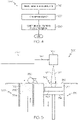
- FIG. 5 is a schematic view of a DMLF system 300 for manufacturing the vibration isolator assembly, for example one or more components of the vibration isolator assembly as shown in FIGS. 1 and 3 , such as the bellows 120 or 122 as shown in FIG. 3 , in accordance with an exemplary embodiment.
- the system 300 includes a fabrication device 310, a powder delivery device 330, a scanner 340, and a laser 360 that function to manufacture the article 350 (e.g., the vibration isolator assembly, or a component thereof) with build material 370.
- the fabrication device 310 includes a build container 312 with a fabrication support 314 on which the article 350 is formed and supported.
- the fabrication support 314 is movable within the build container 312 in a vertical direction and is adjusted in such a way to define a working plane 316.
- the delivery device 330 includes a powder chamber 332 with a delivery support 334 that supports the build material 370 and is also movable in the vertical direction.
- the delivery device 330 further includes a roller or wiper 336 that transfers build material 370 from the delivery device 330 to the fabrication device 310.
- a base block 340 may be installed on the fabrication support 314.
- the fabrication support 314 is lowered and the delivery support 334 is raised.
- the roller or wiper 336 scrapes or otherwise pushes a portion of the build material 370 from the delivery device 330 to form the working plane 316 in the fabrication device 310.
- the laser 360 emits a laser beam 362, which is directed by the scanner 340 onto the build material 370 in the working plane 316 to selectively fuse the build material 370 into a cross-sectional layer of the article 350 according to the design.
- the speed, position, and other operating parameters of the laser beam 362 are controlled to selectively fuse the powder of the build material 370 into larger structures by rapidly melting the powder particles that may melt or diffuse into the solid structure below, and subsequently, cool and re-solidify.
- each layer of build material 370 may include unfused and fused build material 370 that respectively corresponds to the cross-sectional passages and walls that form the article 350.
- the laser beam 362 is relatively low power to selectively fuse the individual layer of build material 370.
- the laser beam 362 may have a power of approximately 50 to 500 Watts, although any suitable power may be provided.
- the fabrication support 314 Upon completion of a respective layer, the fabrication support 314 is lowered and the delivery support 334 is raised. Typically, the fabrication support 314, and thus the article 350, does not move in a horizontal plane during this step.
- the roller or wiper 336 again pushes a portion of the build material 370 from the delivery device 330 to form an additional layer of build material 370 on the working plane 316 of the fabrication device 310.
- the laser beam 362 is movably supported relative to the article 350 and is again controlled to selectively form another cross-sectional layer.
- the article 350 is positioned in a bed of build material 370 as the successive layers are formed such that the unfused and fused material supports subsequent layers. This process is continued according to the modeled design as successive cross-sectional layers are formed into the completed desired portion, e.g., the vibration isolator assembly, or component thereof such as the bellows, of step 220.
- the delivery of build material 370 and movement of the article 350 in the vertical direction are relatively constant and only the movement of the laser beam 362 is selectively controlled to provide a simpler and more precise implementation.
- the localized fusing of the build material 370 enables more precise placement of fused material to reduce or eliminate the occurrence of over-deposition of material and excessive energy or heat, which may otherwise result in cracking or distortion.
- the unused and unfused build material 370 may be reused, thereby further reducing scrap.
- the build material 370 may be formed by any suitable powder, including powdered metals, such as a stainless steel powder, and alloys and super alloy materials, such as nickel-based or cobalt superalloys.
- the build material 370 is a high temperature nickel base super alloy such as IN718.
- MAR-M-247, IN738, titanium, aluminum, titanium-aluminide, or other suitable alloys may be employed.
- the powder build material 370 may be selected for enhanced strength, durability, and useful life, particularly at high temperatures, although as described below, the powder build material 370 may also be selected based on the intended function of the area being formed.
- the article 350 i.e., the vibration isolator assembly
- the vibration isolator assembly formed in step 220 may undergo finishing treatments. Finishing treatments may include, for example, aging, annealing, quenching, peening, polishing, hot isostatic pressing (HIP), or coatings. If necessary, the vibration isolator assembly may be machined to final specifications.
- finishing treatments may include, for example, aging, annealing, quenching, peening, polishing, hot isostatic pressing (HIP), or coatings. If necessary, the vibration isolator assembly may be machined to final specifications.
- a post-laser fusion process of step 230 is a HIP process in which an encapsulation layer is applied and pressure and heat are applied to remove or reduce any porosity and cracks internal to or on the surface of the component, as described in United States Patent Application Serial No. 12/820,652 , titled "METHODS FOR MANUFACTURING TURBINE COMPONENTS.
- the encapsulation layer functions to effectively convert any surface porosity and cracks into internal porosity and cracks, and after the application of pressure and heat, removes or reduces the porosity and cracks.
- Such encapsulation layers may be subsequently removed or maintained to function as an oxidation protection layer.
- the encapsulation layer may be a metal or alloy that is compatible with the substrate and may be applied by a plating or coating process, as described below.
- the HIP process may be performed at a processing temperature in a range of about 1000° C to about 1300° C and may be performed at a pressure in a range of about 1 ksi to about 25 ksi for a time period of about 1 to about 10 hours.
- the HIP processing temperature, pressure, and time may be smaller or larger to form a compacted solid having negligible porosity.
- the method 200 has been discussed above with reference to the formation of a single vibration isolator assembly, or component thereof. However, in one exemplary embodiment of the method 200, more than one vibration isolator assembly (or component thereof) may be manufactured simultaneously. Unless otherwise noted, method 200 in this embodiment proceeds as discussed above.
- the articles are formed on a common base block (e.g., base block 340) to provide a common orientation and a known point of reference and formed as discussed above.
- Successive layers can be formed for the group of articles simultaneously according to a common module or design.
- the powdered metal may be deposited across a single working plane and one or more lasers may selectively fuse the layers of each intermediate turbine article, either sequentially or simultaneously.
- the articles may then be lowered together for the formation of the next layer. Simultaneous fabrication of a number of components may reduce cost and variability of the manufacturing process.
- exemplary embodiments may enhance vibration isolator assemblies fabricated with additive manufacturing techniques, including DMLF/DMLS.
- the utility, design, durability, manufacturing cost, and life span of the vibration isolator assembly may be improved by manufacturing each portion of the vibration isolator assembly using designs that minimize the structural stresses that will be encountered during operation, especially the convolutes of the bellows which, in previously known techniques, were welded or brazed together, resulting in numerous potential points of weakness.
- rapid prototyping and manufacturing reduces cracks and other issues and reduces costs and cycle time in the system design, particularly in the iterative environment of gas turbine engine component design.
- the bellows 120,122 in FIG. 3 may be fabricated with additive manufacturing techniques to provide capability not possible with the prior art.
- a bellows 600 may be axisymmetrically formed about a bellows centerline 601.
- a first pitch length 602 between adjacent convolutes may be different than a second pitch length 604 between two other adjacent convolutes.
- a first wall thickness 610 may be different than a second wall thickness 612.
- the wall thickness distribution in the bellows may be tapered gradually to provide optimal stiffness or improved stress distribution in the bellows.
- a first inner radius 620 may be a different size than a second inner radius of curvature 622
- a first outer radius 630 may be a different size than a second outer radius of curvature 632.
- Various combinations of pitch lengths, thickness distributions, inner radius of curvatures, and outer radii of curvatures may be employed in the bellows to optimize the configuration for performance, life, cost, and weight.
- fabrication using additive manufacturing enables the bellows diameter 640 at a first end to be different from the bellows diameter 642 at a second end if desired for enhanced performance, weight, or assembly, among other reasons.
- the components are submerged in a DMLS machine powder bed.
- the DMLS process is therefore not restrained or limited by conventional roll-forming tooling, which makes this a unique approach to producing the bellows and/or other parts of the vibration isolator assembly.
- the assembly may now be optimized by utilizing variable wall thickness in the bellows.
- the bellows may now be optimized in shape (radius of curvature, variable aspect ratio of the convolutes, tapering of wall thickness or features, etc.) to produce the optimized final assembly.
Description
- The present disclosure generally relates to vibration isolator assemblies and methods of manufacturing vibration isolator assemblies. More particularly, the present disclosure relates to vibration isolator assemblies manufactured using additive manufacturing techniques.
- Many industrial, aerospace, and defense applications require components to be protected from environmental conditions such as vibration. One method of vibration protection is provided via the use of a vibration isolator positioned between the component sought to be protected and the condition causing the vibration. An exemplary class of vibration isolators known in the art includes those implementing Honeywell International Inc.'s D-Strut™ technology, which utilizes a three-parameter spring and damper system that is tuned to reduce system vibrations by incorporating hermetically sealed metallic bellows that are flexible and able to compensate for thermal contraction and/or expansions where rubber expansion joints will not work. An exemplary implementation for such vibration isolator assemblies is in the manufacture of gas turbine engines, wherein the vibration isolators are provided to isolate the aero-acoustic and rotor dynamic engine vibrations from an aircraft structure. Other exemplary implementations for vibration isolators include isolating launch vehicles from rocket motor and aerodynamic vibrations and isolating space telescopes from gyroscopic vibrations.
- While numerous vibration isolator assemblies are known in the art, they all suffer from common challenges. These challenges include, but are not limited to, high part counts, assembly complexities, the requirement of hermetically sealed bellows, and limitations due to manufacturing constraints that may result in a sub-optimal configuration. Furthermore, fabrication of the bellows is costly, and the cycle time associated with the design and fabrication of the assembly is unacceptably high for many applications.
- For example, it is commonly known that the bellows require a seamless and non-porous surface so that pressure can be maintained inside the bellows and dust and/or moisture will not penetrate the seams. Currently, metallic bellows are produced either by expansive-forming or by roll-forming techniques. A limitation of known roll-forming or expansive-forming technologies is the geometry or shape of the metallic bellows. Using existing technology, a bellows can only be circumferential if produced via roll-forming and either round or nearly round if produced via expansive forming.
- Patent document number
DE10-2010-006802A1 describes a fluid-operated linear drive having a working chamber with an elastically deformable wall section for converting fluid pressure forces in a linear motion and has a coupling rod. The working chamber is formed between the elastically deformable wall section and a housing, which surrounds the elastically deformable wall section. The elastically deformable wall section is integrally formed with the dimensionally stable housing. - Patent document number
DE10-2005-056846A1 describes a linear drive having an actuator which can be filled with a medium. A clamping collar and bellows are manufactured in one piece under application of a generative manufacturing method. The clamping collars and bellows are manufactured from a uniform material. - Document
US 2010/320358 A1 discloses a vibration isolator assembly according to the preamble of claim 1. - Hence, there is a need for improved design and manufacturing approaches that enable optimized bellow designs while simultaneously lowering cost and cycle time. The present disclosure addresses at least these needs. Furthermore, other desirable features and characteristics of the vibration isolator assemblies will become apparent from the subsequent detailed description and the appended claims, taken in conjunction with the accompanying drawings and the preceding background.
- The present invention in its various aspects is as set out in the appended claims.
- Disclosed are vibration isolator assemblies and methods for manufacturing vibration isolator assemblies. In one embodiment, an exemplary vibration isolator assembly includes a bellows component, a piston component, a shaft component, and a housing component, wherein at least one of the bellows component, the piston component, the shaft component, and the housing component is formed using additive manufacturing techniques.
- In another embodiment, an exemplary vibration isolator assembly includes a bellows component, a piston component, a shaft component, and a housing component, wherein the bellows component comprises a variable aspect ratio of the convolutes.
- An exemplary method for manufacturing a vibration isolator assembly is disclosed, the vibration isolator assembly including at least a bellows component, a piston component, a shaft component, and a housing component, the method including forming at least one of the bellows component, the piston component, the shaft component, and the housing component using manufacturing techniques; and assembling the bellows component, the piston component, the shaft component, and the housing component into a complete vibration isolator assembly.
- This summary is provided to introduce a selection of concepts in a simplified form that are further described below in the detailed description. This summary is not intended to identify key features or essential features of the claimed subject matter, nor is it intended to be used as an aid in determining the scope of the claimed subject matter.
- The present invention will hereinafter be described in conjunction with the following drawing figures, wherein like numerals denote like elements, and wherein:
-
FIG. 1 is a cross-sectional view of an exemplary of a vibration isolator assembly; -
FIG. 2 is a detailed view of the vibration isolator assembly ofFIG. 1 ; -
FIG. 3 is a perspective view of an exemplary bellows component that may form a part of the vibration isolator assembly as inFIG. 1 ; -
FIG. 4 is a flow diagram illustrating steps in a method of manufacturing a vibration isolator assembly in accordance with an embodiment of the present disclosure; -
FIG. 5 is an exemplary additive manufacturing system suitable for use in manufacturing vibration isolator assemblies in accordance with the present disclosure; and -
FIG. 6 is a cross-sectional view of an exemplary bellows component fabricated using additive manufacturing techniques as illustrated inFIGs. 4 and 5 , and that may that may form a part of the vibration isolator assembly as inFIG. 1 . - The following detailed description is merely exemplary in nature and is not intended to limit the invention or the application and uses of the invention. As used herein, the word "exemplary" means "serving as an example, instance, or illustration." Thus, any embodiment described herein as "exemplary" is not necessarily to be construed as preferred or advantageous over other embodiments. Furthermore, as used herein, numerical ordinals such as "first," "second," "third," etc., such as first, second, and third components, simply denote different singles of a plurality unless specifically defined by language in the appended claims. All of the embodiments and implementations of the vibration isolator assemblies and methods for the manufacture thereof described herein are exemplary embodiments provided to enable persons skilled in the art to make or use the invention and not to limit the scope of the invention which is defined by the claims. Furthermore, there is no intention to be bound by any expressed or implied theory presented in the preceding technical field, background, brief summary, or the following detailed description.
- Disclosed herein is an enhanced vibration isolator assembly that is fabricated using a free-form manufacturing process for its production. Unlike known vibration isolator assemblies, embodiments of the present disclosure utilize a manufacturing process that incorporates a low energy density laser beam, referred to as "direct metal laser sintering" (DMLS) in a powder tank. This "free-form" or additive manufacturing process uses a small, focused beam to build a component by fusing one layer of powder to the fused layer of powder directly beneath it. The manufacturing methods disclosed herein utilize DMLS to build unique designs that are not possible with prior technologies such as investment casting, expansive, or rolled-forming technologies, where costly and time-consuming tooling is required.
- Furthermore, DMLS is a manufacturing technology that is able to produce flexible joint assemblies from multiple materials. Manufacturing methods previously known in the art, such as roll-forming or expansion-forming, have limited capabilities. DMLS is a free-form approach to produce complex, novel designs not possible with methods previously known in the art since DMLS does not require tooling in the manufacturing process. For example, DMLS may be utilized to produce the bellows components of a vibration isolator assembly without the need for expansive- or rolled-forming technologies and without the need for complex welding processes that must maintain sealing all around the bellows.
- Additionally, the methods of the present disclosure allow for optimization of the damper/spring assembly of a vibration isolator assembly by enabling variable wall thicknesses in the bellows assembly in both the thickness and convolute (turn-around) regions. The result thereof is a lower cost and robust assembly (from a sealing perspective) that may be optimized for an individual implementation much faster than previously available in the art.
- Still further, the use of DMLS technology in connection with the manufacturing of vibration isolator assemblies as described herein enables a significant part count reduction from vibration isolator assemblies previously known in the art. Furthermore, by consolidating the entire manufacturing process in one DMLS environment, a fixed process may be employed to reduce variability in the assembly since all units are produced as one (or two) parts from the same machine and process. Multiple parts with their associated tolerance and variability (and defects) are no longer required. The result thereof is a reduced part count, optimized assembly that may be produced with lower cost and reduced cycle time when compared to previously known methods.
- It will be appreciated that the methods presented herein can be applied to any vibration isolator assembly configuration to simplify and reduce the cost of the manufacture thereof, and to improve the reliability of the assembly. For purposes of discussion only, an exemplary vibration isolator assembly is described below with regard to
FIGS. 1 and2 . The illustrated vibration isolator is provided merely as a basis to discuss the various ways in which the methods described herein can be applied to improve the manufacture of vibration isolator assemblies (i.e., to reduce the parts count, to optimize the configuration of the bellows, etc.), and should not be read in any way as limiting on the potential application of such methods. Furthermore, the vibration isolator assembly described in connection withFIGS. 1 and2 serves to illustrate how complicated these multi-piece assemblies are, and therefore why simplification in manufacturing in accordance with the methods presented herein is beneficial. - With reference now to
FIG. 1 , one exemplaryvibration isolator assembly 106 is provided. Thevibration isolator assembly 106 includes apivot 108, anisolator assembly 110, anouter housing 112, and asupport 114. Thepivot 108 receives vibratory motion from a component to which it is coupled. Thepivot 108 can also be considered a contact portion insofar as it contacts the vibrating component and/or component deflecting in response to the vibrations. Theisolator assembly 110 damps and isolates the received vibratory motion and is coupled to thepivot 108 via apivot 116. Theouter housing 112 protects theisolator assembly 110 from damage and is configured to house theisolator assembly 110 therein. Thesupport 114 attaches thevibration isolator assembly 106 to another component, and can be formed on or coupled to any suitable part of theisolator assembly 110. - Turning now to
FIG. 2 , a cross section view of theexemplary isolator assembly 110 is depicted. Theisolator assembly 110 includes anassembly housing 118, a first bellows 120, a second bellows 122, apiston assembly 124, fluid and, optionally, atemperature compensation device 126. Theassembly housing 118 is configured to operate with the other components of theisolator assembly 110 to provide a fixed volume of space and to enclose and seal the fluid therein. Theassembly housing 118 includes at least atube 128 that has afirst end 130, asecond end 132, and aninner surface 134 that defines apassage 138 extending between the first and second ends 130, 132. Theassembly housing 118 also includes alongitudinal axis 142 along which the components in thepassage 138 may travel. Thefirst end 130 includes aninlet 140, thesecond end 132 includes an outlet 141, and thetube 128 has no openings other than theinlet 140 and outlet 141. - The first bellows 120 is disposed within the
assembly housing 118 and is configured to move along thelongitudinal axis 142. The first bellows 120 is coupled at one end to afirst end plate 148 and at an opposite end to asecond end plate 150 to thereby define first bellowsinterior cavity 152 therebetween. Thefirst end plate 148 sealingly mates with the assembly housingfirst end 130 and couples thefirst bellows 120 thereto. Thesecond end plate 150 couples to asupport shaft 158 that is disposed within the first bellowsinterior cavity 152. Thesupport shaft 158 is configured to provide structural support for thefirst bellows 120 and guides thefirst bellows 120 along thelongitudinal axis 142 during operation. Thesupport shaft 158 may itself include acavity 160 configured to receiveother isolator assembly 110 components therein. - Similar to the first bellows 120, the second bellows 122 is disposed within the
assembly housing 118, is coupled to a first and asecond end plate longitudinal axis 142. The second bellowsfirst end plate 166 sealingly mates with the assembly housingsecond end 132 and couples the second bellows 122 thereto. The second bellowssecond end plate 168 is coupled to the opposite end of the second bellows 122 and, together with thefirst end plate 166 and inner surface of the second bellows 122, defines ainterior cavity 170. Just as above, each of the first andsecond end plates openings assembly housing 118. - The
piston assembly 124 is configured to operate with the first andsecond bellows FIG. 1 ). Thepiston assembly 124 is disposed within theassembly housing 118 and is coupled between the first andsecond bellows piston assembly 124 includes apiston shaft 176 andpiston flange 178. Thepiston shaft 176 may be a single or multiple pieces (for example,shaft 176 andsection 177, as shown inFIG. 2 ) and is aligned along thelongitudinal axis 142 and is disposed in the second bellowsinterior cavity 170. Thepiston shaft 176 has an end that is coupled to thepivot 116 and another end that is coupled to thepiston flange 178. Thepiston shaft 176 extends through the second end plate opening 174 of the second bellows 122 and is coupled directly to thepivot 116. Thepiston shaft 176 includes aflowpath 180 extending at least partially therethrough for receiving fluid. One section of theflowpath 180 has threaded walls that are configured to mate with a set screw. - The
piston flange 178 extends radially outward from thepiston shaft 176 and may be either formed integrally as part of thepiston shaft 176 or may be separately constructed and subsequently attached to thepiston shaft 176. Thepiston flange 178 is sealingly coupled to the second bellowssecond end plate 168. Thepiston flange 178 is coupled to thefirst bellows 120 via another section of thepiston 177. Thepiston section 177, in turn, is coupled to the first bellowssecond end plate 150. - The
isolator assembly 110 components are preferably configured to operate together to sealingly enclose the fluid therein in a fixed volume of space. The volume of space is separated into subvolumes, each of which is disposed in afirst chamber 192 and asecond chamber 194. Thefirst chamber 192 is defined by a portion of the assembly housinginner surface 134 and an outer surface of the first bellows 120, and thesecond chamber 194 is defined by another portion of the assembly housinginner surface 134 and an outer surface of the second bellows 122. Thefirst chamber 192,second chamber 194, and restrictive flow passage(s) 198 are filled with fluid. Thus, during the operation of theisolator assembly 110, when a force is exerted on thepiston assembly 124, fluid is pushed from thesecond chamber 194, through therestrictive flow passage 198, into thefirst chamber 192. - For purposes of discussion only, reference will be made to an exemplary bellows, illustrated in
FIG. 3 , which may be implemented asbellows FIGS. 1 and2 . As will be described in greater detail below, one aspect of embodiments of the present disclosure is that the components are submerged in a DMLS machine powder bed. The DMLS process is not restrained or limited by conventional roll-forming tooling, which makes this a unique approach to producing the bellows and/or other components of the vibration isolator assembly. Unlike previous methods, the vibration isolator assembly may now be optimized by utilizing, for example, a variable wall thickness in the bellows. With continued reference toFIG. 3 ,reference numeral 121, which highlights a portion of the bellows wall, is indicative of the features of the bellows that can be made to have a variable thickness, in contrast to present designs that are limited to a uniform thickness and require welding at each convolute. - In addition, the bellows (120, 122) may now be optimized in shape (radius of curvature, variable aspect ratio of the convolutes, tapering of wall thickness or features, etc.) to produce the optimized final assembly. Still further, multiple materials may be utilized in the assembly build, as described in commonly assigned patent application serial no.
13/360,126 - Other recent advances may be combined with embodiments of the present disclosure to produce an enhanced vibration isolator assembly. For example, the deficiencies in prior art additive manufacturing methods have been recently overcome by using DMLS in conjunction with super alloy materials, which may require an encapsulation technology as disclosed in commonly assigned patent application serial no.
12/820,652 13/235,210 - In general, it is expected that, based on the teachings herein, a person having ordinary skill in the art will be able to modify the vibration isolator assemblies as above to conform for use in a wide variety of applications, as the selection of size, shape, etc. of working components is generally considered to be within the level of skill of a person having ordinary skill in the art. As such, the various possible implementations of the vibration isolator assemblies should not be considered limited to any of the embodiments presented herein.
- Greater detail regarding the additive manufacturing techniques noted above will now be provided, again with reference to the exemplary bellows illustrated in
FIG. 3 and more generally to the exemplary vibrator isolator assembly illustrated inFIGS. 1 and2 . It will be appreciated that certain features of the presently described vibration isolator assemblies would be prohibitively expensive to manufacture using conventional manufacturing techniques. These include the contoured or curved inlets, the varying wall thickness features, and the structurally compliant connection portions, among others. As such, designs in accordance with the present disclosure are not known in the prior art. However, it has been discovered that using additive manufacturing techniques, or other recently developed manufacturing techniques, designs in accordance with the present disclosure can be manufactured at a significantly reduced cost as compared to traditional manufacturing techniques. Additive manufacturing techniques include, for example, direct metal laser sintering (DMLS - a form of direct metal laser fusion (DMLF)) with nickel base super-alloys, low density titanium, and aluminum alloys. DMLS is discussed in greater detail below. Another technique includes electron beam melting (EBM) with titanium, titanium aluminide, and nickel base super-alloy materials. Still further, casting or metal injection molding (MIM) may be employed. -
FIG. 4 is a flowchart illustrating amethod 200 for manufacturing a vibration isolator assembly such as thebellows bellows - In a
first step 210, a model, such as a design model, of the vibration isolator assembly, or component thereof such as thebellows - In
step 220 of themethod 200, the vibration isolator assembly, or component thereof, is formed according to the model ofstep 210. In one exemplary embodiment, a portion of the vibration isolator assembly is formed using a rapid prototyping or additive layer manufacturing process. In other embodiments, the entire vibration isolator assembly is formed using a rapid prototyping or additive layer manufacturing process. Although additive layer manufacturing processes are described in greater detail below, in still other alternative embodiments, portions of the vibration isolator assembly may be forged or cast instep 220, for example, with a single-crystal structure. - Some examples of additive layer manufacturing processes include: micro-pen deposition in which liquid media is dispensed with precision at the pen tip and then cured; selective laser sintering in which a laser is used to sinter a powder media in precisely controlled locations; laser wire deposition in which a wire feedstock is melted by a laser and then deposited and solidified in precise locations to build the product; electron beam melting; laser engineered net shaping; and direct metal deposition. In general, additive manufacturing techniques provide flexibility in free-form fabrication without geometric constraints, fast material processing time, and innovative joining techniques. In one particular exemplary embodiment, direct metal laser fusion (DMLF) is used to produce the vibration isolator assembly in
step 220. DMLF is a commercially available laser-based rapid prototyping and tooling process by which complex parts may be directly produced by precision melting and solidification of metal powder into successive layers of larger structures, each layer corresponding to a cross-sectional layer of the 3D component. DMLF may include direct metal laser sintering (DMLS), as previously noted above, and is a particularly preferred embodiment of this disclosure. - As such, in one exemplary embodiment,
step 220 is performed with DMLF techniques to form the vibration isolator assembly. However, prior to a discussion of the subsequent method steps, reference is made toFIG. 5 , which is a schematic view of aDMLF system 300 for manufacturing the vibration isolator assembly, for example one or more components of the vibration isolator assembly as shown inFIGS. 1 and3 , such as thebellows FIG. 3 , in accordance with an exemplary embodiment. - Referring to
FIG. 5 , thesystem 300 includes afabrication device 310, apowder delivery device 330, ascanner 340, and alaser 360 that function to manufacture the article 350 (e.g., the vibration isolator assembly, or a component thereof) withbuild material 370. Thefabrication device 310 includes abuild container 312 with afabrication support 314 on which thearticle 350 is formed and supported. Thefabrication support 314 is movable within thebuild container 312 in a vertical direction and is adjusted in such a way to define a workingplane 316. Thedelivery device 330 includes apowder chamber 332 with adelivery support 334 that supports thebuild material 370 and is also movable in the vertical direction. Thedelivery device 330 further includes a roller orwiper 336 that transfersbuild material 370 from thedelivery device 330 to thefabrication device 310. - During operation, a
base block 340 may be installed on thefabrication support 314. Thefabrication support 314 is lowered and thedelivery support 334 is raised. The roller orwiper 336 scrapes or otherwise pushes a portion of thebuild material 370 from thedelivery device 330 to form the workingplane 316 in thefabrication device 310. Thelaser 360 emits alaser beam 362, which is directed by thescanner 340 onto thebuild material 370 in the workingplane 316 to selectively fuse thebuild material 370 into a cross-sectional layer of thearticle 350 according to the design. More specifically, the speed, position, and other operating parameters of thelaser beam 362 are controlled to selectively fuse the powder of thebuild material 370 into larger structures by rapidly melting the powder particles that may melt or diffuse into the solid structure below, and subsequently, cool and re-solidify. As such, based on the control of thelaser beam 362, each layer ofbuild material 370 may include unfused and fusedbuild material 370 that respectively corresponds to the cross-sectional passages and walls that form thearticle 350. In general, thelaser beam 362 is relatively low power to selectively fuse the individual layer ofbuild material 370. As an example, thelaser beam 362 may have a power of approximately 50 to 500 Watts, although any suitable power may be provided. - Upon completion of a respective layer, the
fabrication support 314 is lowered and thedelivery support 334 is raised. Typically, thefabrication support 314, and thus thearticle 350, does not move in a horizontal plane during this step. The roller orwiper 336 again pushes a portion of thebuild material 370 from thedelivery device 330 to form an additional layer ofbuild material 370 on the workingplane 316 of thefabrication device 310. Thelaser beam 362 is movably supported relative to thearticle 350 and is again controlled to selectively form another cross-sectional layer. As such, thearticle 350 is positioned in a bed ofbuild material 370 as the successive layers are formed such that the unfused and fused material supports subsequent layers. This process is continued according to the modeled design as successive cross-sectional layers are formed into the completed desired portion, e.g., the vibration isolator assembly, or component thereof such as the bellows, ofstep 220. - The delivery of
build material 370 and movement of thearticle 350 in the vertical direction are relatively constant and only the movement of thelaser beam 362 is selectively controlled to provide a simpler and more precise implementation. The localized fusing of thebuild material 370 enables more precise placement of fused material to reduce or eliminate the occurrence of over-deposition of material and excessive energy or heat, which may otherwise result in cracking or distortion. The unused andunfused build material 370 may be reused, thereby further reducing scrap. - Any suitable laser and laser parameters may be used, including considerations with respect to power, laser beam spot size, and scanning velocity. As a general matter, the
build material 370 may be formed by any suitable powder, including powdered metals, such as a stainless steel powder, and alloys and super alloy materials, such as nickel-based or cobalt superalloys. In one exemplary embodiment, thebuild material 370 is a high temperature nickel base super alloy such as IN718. In other embodiments, MAR-M-247, IN738, titanium, aluminum, titanium-aluminide, or other suitable alloys may be employed. In general, thepowder build material 370 may be selected for enhanced strength, durability, and useful life, particularly at high temperatures, although as described below, thepowder build material 370 may also be selected based on the intended function of the area being formed. - Returning to
FIG. 4 , at the completion ofstep 220, thearticle 350, i.e., the vibration isolator assembly, is removed from the additive manufacturing system (e.g., from the DMLF system 300). Inoptional step 230, the vibration isolator assembly formed instep 220 may undergo finishing treatments. Finishing treatments may include, for example, aging, annealing, quenching, peening, polishing, hot isostatic pressing (HIP), or coatings. If necessary, the vibration isolator assembly may be machined to final specifications. As noted above, one example of a post-laser fusion process ofstep 230 is a HIP process in which an encapsulation layer is applied and pressure and heat are applied to remove or reduce any porosity and cracks internal to or on the surface of the component, as described inUnited States Patent Application Serial No. 12/820,652 , titled "METHODS FOR MANUFACTURING TURBINE COMPONENTS. The encapsulation layer functions to effectively convert any surface porosity and cracks into internal porosity and cracks, and after the application of pressure and heat, removes or reduces the porosity and cracks. Such encapsulation layers may be subsequently removed or maintained to function as an oxidation protection layer. - In one exemplary embodiment, the encapsulation layer may be a metal or alloy that is compatible with the substrate and may be applied by a plating or coating process, as described below. In one embodiment, the HIP process may be performed at a processing temperature in a range of about 1000° C to about 1300° C and may be performed at a pressure in a range of about 1 ksi to about 25 ksi for a time period of about 1 to about 10 hours. In other embodiments, the HIP processing temperature, pressure, and time may be smaller or larger to form a compacted solid having negligible porosity.
- The
method 200 has been discussed above with reference to the formation of a single vibration isolator assembly, or component thereof. However, in one exemplary embodiment of themethod 200, more than one vibration isolator assembly (or component thereof) may be manufactured simultaneously. Unless otherwise noted,method 200 in this embodiment proceeds as discussed above. In this embodiment of themethod 200, the articles are formed on a common base block (e.g., base block 340) to provide a common orientation and a known point of reference and formed as discussed above. Successive layers can be formed for the group of articles simultaneously according to a common module or design. For example, the powdered metal may be deposited across a single working plane and one or more lasers may selectively fuse the layers of each intermediate turbine article, either sequentially or simultaneously. The articles may then be lowered together for the formation of the next layer. Simultaneous fabrication of a number of components may reduce cost and variability of the manufacturing process. - Accordingly, exemplary embodiments may enhance vibration isolator assemblies fabricated with additive manufacturing techniques, including DMLF/DMLS. In particular, the utility, design, durability, manufacturing cost, and life span of the vibration isolator assembly may be improved by manufacturing each portion of the vibration isolator assembly using designs that minimize the structural stresses that will be encountered during operation, especially the convolutes of the bellows which, in previously known techniques, were welded or brazed together, resulting in numerous potential points of weakness. Additionally, rapid prototyping and manufacturing reduces cracks and other issues and reduces costs and cycle time in the system design, particularly in the iterative environment of gas turbine engine component design.
- For example, the bellows 120,122 in
FIG. 3 may be fabricated with additive manufacturing techniques to provide capability not possible with the prior art. For example, and referring now toFIG. 6 , abellows 600 may be axisymmetrically formed about abellows centerline 601. Afirst pitch length 602 between adjacent convolutes may be different than asecond pitch length 604 between two other adjacent convolutes. Similarly, afirst wall thickness 610 may be different than asecond wall thickness 612. The wall thickness distribution in the bellows may be tapered gradually to provide optimal stiffness or improved stress distribution in the bellows. Similarly, a firstinner radius 620 may be a different size than a second inner radius ofcurvature 622, and a firstouter radius 630 may be a different size than a second outer radius ofcurvature 632. Various combinations of pitch lengths, thickness distributions, inner radius of curvatures, and outer radii of curvatures may be employed in the bellows to optimize the configuration for performance, life, cost, and weight. In addition, fabrication using additive manufacturing enables thebellows diameter 640 at a first end to be different from thebellows diameter 642 at a second end if desired for enhanced performance, weight, or assembly, among other reasons. - As noted in the present disclosure, in implementing the DMLS methods described herein, the components are submerged in a DMLS machine powder bed. The DMLS process is therefore not restrained or limited by conventional roll-forming tooling, which makes this a unique approach to producing the bellows and/or other parts of the vibration isolator assembly. Unlike previously known fabrication techniques, the assembly may now be optimized by utilizing variable wall thickness in the bellows. In addition, the bellows may now be optimized in shape (radius of curvature, variable aspect ratio of the convolutes, tapering of wall thickness or features, etc.) to produce the optimized final assembly.
- While at least one exemplary embodiment has been presented in the foregoing detailed description, it should be appreciated that a vast number of variations exist within the scope of the appended claims. It should also be appreciated that the exemplary embodiments of the vibration isolator assembly are only examples, and are intended to be limited only by the scope, applicability, or configuration of the invention as defined in the appended claims. Rather, the foregoing detailed description will provide those skilled in the art with a convenient road map for implementing an exemplary embodiment of the inventive vibration isolator assembly accordingly to the appended claims. It is understood that various changes may be made in the function and arrangement of elements described in an exemplary embodiment without departing from the scope of the invention as set forth in the appended claims.
Claims (3)
- A vibration isolator assembly (106) comprising: a pivot (108), an isolator assembly (110), an outer housing (112), and a support (114); whereinthe pivot is configured to receive vibratory motion;the isolator assembly (110) is coupled to the pivot (108) via a pivot (116) and is configured to damp and isolates the received vibratory motion;the outer housing (112) is configured to house the isolator assembly (110) therein and is configured to protect the isolator assembly (110) from damage; andthe support (114) is configured to attach the vibration isolator assembly (106) to another component;the isolator assembly (110) includes an assembly housing (118), a first bellows (120), a second bellows (122), a piston assembly (124) and fluid; whereinthe assembly housing (118) is configured to operate with the other components of the isolator assembly (110) to provide a fixed volume of space and to enclose and seal the fluid therein;the assembly housing (118) comprises a tube (128) that has a first end (130), a second end (132), and an inner surface (134) that defines a passage (138) extending between the first and second ends (130, 132); wherein the first end (130) includes an inlet (140), the second end (132) includes an outlet (141), and the tube (128) has no openings other than the inlet (140) and outlet (141);the assembly housing (118) has a longitudinal axis (142) along which the components in the passage (138) may travel;the first bellows (120) and second bellows (122) are disposed within the assembly housing (118) and are configured to move along the longitudinal axis (142); whereinthe first bellows (120) is coupled at one end to a first bellows first end plate (148) and at an opposite end to a first bellows second end plate (150) to thereby define first bellows interior cavity (152) therebetween; the first bellows first end plate (148) is sealingly mated with the assembly housing first end (130) and couples the first bellows (120) thereto, the first bellows second end plate (150) is coupled to a support shaft (158) that is disposed within the first bellows interior cavity (152); and the support shaft (158) is configured to provide structural support for the first bellows (120) and guides the first bellows (120) along the longitudinal axis (142) during operation;the second bellows (122) is disposed within the assembly housing (118), is coupled to a second bellows first end plate (166) and a second bellows second end plate (168); the second bellows first end plate (166) sealingly mates with the assembly housing second end (132) and couples the second bellows (122) thereto, the second bellows second end plate (168) is coupled to the opposite end of the second bellows (122) and, together with the first end plate (166) and inner surface of the second bellows (122), defines a second bellows interior cavity (170), and each of the second bellows first end plate (166) and second bellows second end plates (168) comprise openings (172, 174);the first and second bellows components comprise:a variable radius of curvature; the piston assembly (124) is configured to operate with the first and second bellows (120, 122) to damp and isolate vibration received from the pivot (116);the piston assembly (124) is disposed within the assembly housing (118) and is coupled between the first and second bellows (120, 122);the piston assembly (124) comprises a piston shaft (176) and piston flange (178); wherein the piston shaft (176):is aligned along the longitudinal axis (142) and is disposed in the second bellows interior cavity (170),has an end that is coupled to the pivot (116) and another end that is coupled to the piston flange (178) and extends through the second end plate opening (174), andis coupled directly to the pivot (116) and includes a flowpath (180) extending at least partially therethrough for receiving fluid; wherein one section of the flowpath (180) has threaded walls that are configured to mate with a set screw;wherein the piston flange (178):extends radially outward from the piston shaft (176),is sealingly coupled to the second bellows second end plate (168), andis coupled to the first bellows (120) via another section of the piston (177);wherein the piston section (177), in turn, is coupled to the first bellows second end plate (150), characterised in thatthe first and second bellows components comprise:a tapering of wall thickness; andwherein a first pitch length (602) between adjacent convolutes is different than a second pitch length (604) between two other adjacent convolutes.
- The vibration isolator assembly of claim 1, wherein the first and second bellows components and at least one of the piston component, the shaft component, and the housing component are formed as an integral structure.
- The vibration isolator assembly of claim 2, wherein the integral structure is formed using additive manufacturing techniques.
Applications Claiming Priority (1)
| Application Number | Priority Date | Filing Date | Title |
|---|---|---|---|
| US13/540,409 US10900537B2 (en) | 2012-07-02 | 2012-07-02 | Vibration isolator assemblies and methods for the manufacture thereof |
Publications (3)
| Publication Number | Publication Date |
|---|---|
| EP2682207A2 EP2682207A2 (en) | 2014-01-08 |
| EP2682207A3 EP2682207A3 (en) | 2018-03-07 |
| EP2682207B1 true EP2682207B1 (en) | 2022-11-16 |
Family
ID=48782868
Family Applications (1)
| Application Number | Title | Priority Date | Filing Date |
|---|---|---|---|
| EP13173121.8A Active EP2682207B1 (en) | 2012-07-02 | 2013-06-20 | Vibration isolator assembly |
Country Status (3)
| Country | Link |
|---|---|
| US (1) | US10900537B2 (en) |
| EP (1) | EP2682207B1 (en) |
| JP (1) | JP6377323B2 (en) |
Families Citing this family (12)
| Publication number | Priority date | Publication date | Assignee | Title |
|---|---|---|---|---|
| JP6245906B2 (en) * | 2013-09-13 | 2017-12-13 | 公益財団法人鉄道総合技術研究所 | Brake disc and manufacturing method thereof |
| DE102014208040B4 (en) | 2014-04-29 | 2019-09-12 | MTU Aero Engines AG | Bearing cage and bearing device with such a bearing cage and method for forming, repairing and / or replacing such a bearing cage |
| US9850968B2 (en) * | 2014-04-29 | 2017-12-26 | Goodrich Corporation | Torque bar and methods for making |
| EP3002212B1 (en) * | 2014-09-30 | 2017-06-14 | Safran Landing Systems UK Limited | Aerospace component and method for producing an aerospace component |
| EP3242763A4 (en) * | 2015-01-05 | 2018-08-29 | Sikorsky Aircraft Corporation | Integrated vibration damper for additively manufactured structure and method |
| US10486232B2 (en) * | 2015-04-21 | 2019-11-26 | Varian Semiconductor Equipment Associates, Inc. | Semiconductor manufacturing device with embedded fluid conduits |
| US11028923B2 (en) | 2015-06-11 | 2021-06-08 | Hamilton Sundstrand Corporation | High vibration pneumatic piston assembly made from additive manufacturing |
| US9879566B2 (en) | 2015-07-07 | 2018-01-30 | Honeywell International Inc. | Turbine engine couplings and methods for manufacturing turbine engine couplings |
| US10801653B2 (en) | 2017-10-13 | 2020-10-13 | Honeywell International Inc. | Flexible, thermal-isolating, dual-walled tube with bellows and method for manufacture thereof |
| US11097835B2 (en) * | 2019-01-30 | 2021-08-24 | Goodrich Corporation | Additively manufactured thermoplastic metering pin with slots for retention hardware |
| DE102020210538A1 (en) * | 2020-08-19 | 2022-02-24 | Thyssenkrupp Ag | Vibration damper and a damper tube for a vibration damper |
| DE102021002971A1 (en) * | 2021-06-10 | 2022-12-15 | Hydac Technology Gmbh | Separating element and hydraulic accumulator with such a separating element |
Citations (1)
| Publication number | Priority date | Publication date | Assignee | Title |
|---|---|---|---|---|
| EP1950439A1 (en) * | 2005-10-25 | 2008-07-30 | NOK Corporation | Boot for universal joint |
Family Cites Families (31)
| Publication number | Priority date | Publication date | Assignee | Title |
|---|---|---|---|---|
| US213150A (en) | 1879-03-11 | Improvement in swings | ||
| DE3244997A1 (en) * | 1982-12-04 | 1984-06-14 | Festo-Maschinenfabrik Gottlieb Stoll, 7300 Esslingen | SHOCK ABSORBER |
| US4837697A (en) | 1987-07-31 | 1989-06-06 | Allied-Signal Inc. | Overspeed governor for an electronic controlled fuel system |
| US5246215A (en) | 1989-06-16 | 1993-09-21 | Nhk Spring Co., Ltd. | Spring seat member with notch for ground spring end |
| DE4128465C1 (en) | 1991-08-28 | 1993-02-25 | Mercedes-Benz Aktiengesellschaft, 7000 Stuttgart, De | |
| US5992584A (en) * | 1996-03-26 | 1999-11-30 | The United States Of America As Represented By The Secretary Of The Navy | Dashpot for power cylinder |
| AU9776498A (en) * | 1997-09-26 | 1999-04-23 | Vistek Inc. | Micro vibration isolation device |
| JPH11159551A (en) | 1997-11-27 | 1999-06-15 | Tama Spring:Kk | Non-linear deformed coil spring |
| JP4016370B2 (en) | 1999-03-29 | 2007-12-05 | 株式会社デンソー | solenoid valve |
| US7394909B1 (en) | 2000-09-25 | 2008-07-01 | Phonak Ag | Hearing device with embedded channnel |
| US6634472B1 (en) * | 2002-04-03 | 2003-10-21 | Toren S. Davis | Tuned mass damper with translational axis damping |
| US6968923B2 (en) * | 2003-07-30 | 2005-11-29 | Control Components, Inc. | Reduced noise valve stack connection |
| US20050217954A1 (en) * | 2004-03-31 | 2005-10-06 | Hindle Timothy A | Viscous isolation and damping strut utilizing a fluid mass effect |
| WO2006029174A2 (en) | 2004-09-08 | 2006-03-16 | University Of Washington | Energy absorbent material |
| CN101267852B (en) | 2005-07-22 | 2010-12-08 | 麦德托尼克公司 | Miniature pump for drug delivery |
| DE102005056846B4 (en) | 2005-11-28 | 2007-10-18 | Fraunhofer-Gesellschaft zur Förderung der angewandten Forschung e.V. | Linear drive with an actuator that can be filled with a medium |
| US7235990B1 (en) * | 2005-12-12 | 2007-06-26 | Suss Microtec Test Systems Gmbh | Probe station comprising a bellows with EMI shielding capabilities |
| JP2008229986A (en) * | 2007-03-19 | 2008-10-02 | Toyoda Gosei Co Ltd | Bellows hollow body |
| US8043684B2 (en) | 2008-02-14 | 2011-10-25 | United Technologies Corporation | Low transient and steady state thermal stress disk shaped components |
| GB0806073D0 (en) | 2008-04-03 | 2008-05-14 | Cadillac Rubber & Plastics Inc | Hydraulically damped mounting device |
| EP2293727A1 (en) * | 2008-05-28 | 2011-03-16 | Kerflin Orthopedic Innovations, Llc | Fluid-powered elongation instrumentation for correcting orthopedic deformities |
| JP2010101377A (en) | 2008-10-22 | 2010-05-06 | Ntn Corp | Constant velocity universal joint boot |
| US8327985B2 (en) * | 2009-06-22 | 2012-12-11 | Honeywell International Inc. | Two stage vibration isolator |
| CA2788249A1 (en) | 2009-12-30 | 2011-07-07 | Beat Lechmann | Intergrated multi-material implants and methods of manufacture |
| DE102010006802A1 (en) | 2010-02-04 | 2011-08-04 | FESTO AG & Co. KG, 73734 | Fluid-operated linear drive has working chamber with elastically deformable wall section for converting fluid pressure forces in linear motion and has coupling rod |
| GB201007257D0 (en) | 2010-04-29 | 2010-06-16 | Materialise Nv | Improved fixating component for a fixture |
| US8487210B2 (en) | 2010-06-11 | 2013-07-16 | W. C. Hereaus GmbH | Joined dissimilar materials and method |
| US8851194B2 (en) * | 2011-03-29 | 2014-10-07 | David L. Ford | Seal with bellows style nose ring |
| US9103403B2 (en) * | 2011-04-25 | 2015-08-11 | Honeywell International Inc. | Three parameter, multi-axis isolators, isolation systems employing the same, and methods for producing the same |
| US8985234B2 (en) | 2011-11-15 | 2015-03-24 | Cnh Industrial Canada, Ltd. | System for applying down pressure in a coulter assembly |
| US10113434B2 (en) * | 2012-01-31 | 2018-10-30 | United Technologies Corporation | Turbine blade damper seal |
-
2012
- 2012-07-02 US US13/540,409 patent/US10900537B2/en active Active
-
2013
- 2013-06-20 EP EP13173121.8A patent/EP2682207B1/en active Active
- 2013-06-25 JP JP2013132666A patent/JP6377323B2/en active Active
Patent Citations (1)
| Publication number | Priority date | Publication date | Assignee | Title |
|---|---|---|---|---|
| EP1950439A1 (en) * | 2005-10-25 | 2008-07-30 | NOK Corporation | Boot for universal joint |
Also Published As
| Publication number | Publication date |
|---|---|
| EP2682207A2 (en) | 2014-01-08 |
| JP6377323B2 (en) | 2018-08-22 |
| US10900537B2 (en) | 2021-01-26 |
| US20150047935A1 (en) | 2015-02-19 |
| EP2682207A3 (en) | 2018-03-07 |
| JP2014040910A (en) | 2014-03-06 |
Similar Documents
| Publication | Publication Date | Title |
|---|---|---|
| EP2682207B1 (en) | Vibration isolator assembly | |
| EP2865981B1 (en) | Counter-flow heat exchange systems | |
| US20200355304A1 (en) | Flexible, thermal-isolating, dual-walled tube with bellows and method for manufacture thereof | |
| EP2620594B1 (en) | Manufacturing method of multi-materials turbine components | |
| EP2540419B1 (en) | Methods for manufacturing engine components with structural bridge devices | |
| US9562616B2 (en) | Spring assemblies for use in gas turbine engines and methods for their manufacture | |
| EP2754515B1 (en) | Methods for the manufacture of gas turbine engine components using additive manufacturing techniques | |
| EP2708296B1 (en) | Methods for manufacturing turbine stator airfoil assemblies by additive manufacturing | |
| EP3702069B1 (en) | Titanium aluminide components from articles formed by consolidation processes | |
| US8685314B2 (en) | Method of joining components | |
| EP3072611A2 (en) | Net-shape or near-net shape powder metal components and methods for producing the same | |
| JP2006297482A (en) | Assembly and method of manufacture of a component by hot isostatic pressing | |
| EP3115670B1 (en) | Turbine engine couplings and methods for manufacturing turbine engine couplings | |
| US20160245519A1 (en) | Panel with cooling holes and methods for fabricating same | |
| WO2020236881A1 (en) | Engine apparatus and method for operation | |
| EP3650138B1 (en) | Cold spray forming | |
| EP3187282B1 (en) | Dynamic bonding of powder metallurgy materials |
Legal Events
| Date | Code | Title | Description |
|---|---|---|---|
| PUAI | Public reference made under article 153(3) epc to a published international application that has entered the european phase |
Free format text: ORIGINAL CODE: 0009012 |
|
| 17P | Request for examination filed |
Effective date: 20130620 |
|
| AK | Designated contracting states |
Kind code of ref document: A2 Designated state(s): AL AT BE BG CH CY CZ DE DK EE ES FI FR GB GR HR HU IE IS IT LI LT LU LV MC MK MT NL NO PL PT RO RS SE SI SK SM TR |
|
| AX | Request for extension of the european patent |
Extension state: BA ME |
|
| RAP1 | Party data changed (applicant data changed or rights of an application transferred) |
Owner name: HONEYWELL INTERNATIONAL INC. |
|
| PUAL | Search report despatched |
Free format text: ORIGINAL CODE: 0009013 |
|
| STAA | Information on the status of an ep patent application or granted ep patent |
Free format text: STATUS: EXAMINATION IS IN PROGRESS |
|
| AK | Designated contracting states |
Kind code of ref document: A3 Designated state(s): AL AT BE BG CH CY CZ DE DK EE ES FI FR GB GR HR HU IE IS IT LI LT LU LV MC MK MT NL NO PL PT RO RS SE SI SK SM TR |
|
| AX | Request for extension of the european patent |
Extension state: BA ME |
|
| RIC1 | Information provided on ipc code assigned before grant |
Ipc: F16F 9/10 20060101ALI20180129BHEP Ipc: B22F 3/24 20060101ALI20180129BHEP Ipc: F16F 9/32 20060101ALI20180129BHEP Ipc: F16F 9/19 20060101ALI20180129BHEP Ipc: B22F 3/105 20060101AFI20180129BHEP Ipc: B22F 5/10 20060101ALI20180129BHEP |
|
| 17Q | First examination report despatched |
Effective date: 20180222 |
|
| STAA | Information on the status of an ep patent application or granted ep patent |
Free format text: STATUS: EXAMINATION IS IN PROGRESS |
|
| GRAP | Despatch of communication of intention to grant a patent |
Free format text: ORIGINAL CODE: EPIDOSNIGR1 |
|
| STAA | Information on the status of an ep patent application or granted ep patent |
Free format text: STATUS: GRANT OF PATENT IS INTENDED |
|
| INTG | Intention to grant announced |
Effective date: 20220829 |
|
| GRAJ | Information related to disapproval of communication of intention to grant by the applicant or resumption of examination proceedings by the epo deleted |
Free format text: ORIGINAL CODE: EPIDOSDIGR1 |
|
| GRAL | Information related to payment of fee for publishing/printing deleted |
Free format text: ORIGINAL CODE: EPIDOSDIGR3 |
|
| GRAS | Grant fee paid |
Free format text: ORIGINAL CODE: EPIDOSNIGR3 |
|
| GRAA | (expected) grant |
Free format text: ORIGINAL CODE: 0009210 |
|
| STAA | Information on the status of an ep patent application or granted ep patent |
Free format text: STATUS: THE PATENT HAS BEEN GRANTED |
|
| AK | Designated contracting states |
Kind code of ref document: B1 Designated state(s): AL AT BE BG CH CY CZ DE DK EE ES FI FR GB GR HR HU IE IS IT LI LT LU LV MC MK MT NL NO PL PT RO RS SE SI SK SM TR |
|
| INTG | Intention to grant announced |
Effective date: 20220829 |
|
| REG | Reference to a national code |
Ref country code: GB Ref legal event code: FG4D |
|
| REG | Reference to a national code |
Ref country code: CH Ref legal event code: EP |
|
| REG | Reference to a national code |
Ref country code: IE Ref legal event code: FG4D |
|
| REG | Reference to a national code |
Ref country code: DE Ref legal event code: R096 Ref document number: 602013082868 Country of ref document: DE |
|
| REG | Reference to a national code |
Ref country code: AT Ref legal event code: REF Ref document number: 1531467 Country of ref document: AT Kind code of ref document: T Effective date: 20221215 |
|
| REG | Reference to a national code |
Ref country code: LT Ref legal event code: MG9D |
|
| REG | Reference to a national code |
Ref country code: NL Ref legal event code: MP Effective date: 20221116 |
|
| REG | Reference to a national code |
Ref country code: AT Ref legal event code: MK05 Ref document number: 1531467 Country of ref document: AT Kind code of ref document: T Effective date: 20221116 |
|
| PG25 | Lapsed in a contracting state [announced via postgrant information from national office to epo] |
Ref country code: SE Free format text: LAPSE BECAUSE OF FAILURE TO SUBMIT A TRANSLATION OF THE DESCRIPTION OR TO PAY THE FEE WITHIN THE PRESCRIBED TIME-LIMIT Effective date: 20221116 Ref country code: PT Free format text: LAPSE BECAUSE OF FAILURE TO SUBMIT A TRANSLATION OF THE DESCRIPTION OR TO PAY THE FEE WITHIN THE PRESCRIBED TIME-LIMIT Effective date: 20230316 Ref country code: NO Free format text: LAPSE BECAUSE OF FAILURE TO SUBMIT A TRANSLATION OF THE DESCRIPTION OR TO PAY THE FEE WITHIN THE PRESCRIBED TIME-LIMIT Effective date: 20230216 Ref country code: LT Free format text: LAPSE BECAUSE OF FAILURE TO SUBMIT A TRANSLATION OF THE DESCRIPTION OR TO PAY THE FEE WITHIN THE PRESCRIBED TIME-LIMIT Effective date: 20221116 Ref country code: FI Free format text: LAPSE BECAUSE OF FAILURE TO SUBMIT A TRANSLATION OF THE DESCRIPTION OR TO PAY THE FEE WITHIN THE PRESCRIBED TIME-LIMIT Effective date: 20221116 Ref country code: ES Free format text: LAPSE BECAUSE OF FAILURE TO SUBMIT A TRANSLATION OF THE DESCRIPTION OR TO PAY THE FEE WITHIN THE PRESCRIBED TIME-LIMIT Effective date: 20221116 Ref country code: AT Free format text: LAPSE BECAUSE OF FAILURE TO SUBMIT A TRANSLATION OF THE DESCRIPTION OR TO PAY THE FEE WITHIN THE PRESCRIBED TIME-LIMIT Effective date: 20221116 |
|
| PG25 | Lapsed in a contracting state [announced via postgrant information from national office to epo] |
Ref country code: RS Free format text: LAPSE BECAUSE OF FAILURE TO SUBMIT A TRANSLATION OF THE DESCRIPTION OR TO PAY THE FEE WITHIN THE PRESCRIBED TIME-LIMIT Effective date: 20221116 Ref country code: PL Free format text: LAPSE BECAUSE OF FAILURE TO SUBMIT A TRANSLATION OF THE DESCRIPTION OR TO PAY THE FEE WITHIN THE PRESCRIBED TIME-LIMIT Effective date: 20221116 Ref country code: LV Free format text: LAPSE BECAUSE OF FAILURE TO SUBMIT A TRANSLATION OF THE DESCRIPTION OR TO PAY THE FEE WITHIN THE PRESCRIBED TIME-LIMIT Effective date: 20221116 Ref country code: IS Free format text: LAPSE BECAUSE OF FAILURE TO SUBMIT A TRANSLATION OF THE DESCRIPTION OR TO PAY THE FEE WITHIN THE PRESCRIBED TIME-LIMIT Effective date: 20230316 Ref country code: HR Free format text: LAPSE BECAUSE OF FAILURE TO SUBMIT A TRANSLATION OF THE DESCRIPTION OR TO PAY THE FEE WITHIN THE PRESCRIBED TIME-LIMIT Effective date: 20221116 Ref country code: GR Free format text: LAPSE BECAUSE OF FAILURE TO SUBMIT A TRANSLATION OF THE DESCRIPTION OR TO PAY THE FEE WITHIN THE PRESCRIBED TIME-LIMIT Effective date: 20230217 |
|
| PG25 | Lapsed in a contracting state [announced via postgrant information from national office to epo] |
Ref country code: NL Free format text: LAPSE BECAUSE OF FAILURE TO SUBMIT A TRANSLATION OF THE DESCRIPTION OR TO PAY THE FEE WITHIN THE PRESCRIBED TIME-LIMIT Effective date: 20221116 |
|
| P01 | Opt-out of the competence of the unified patent court (upc) registered |
Effective date: 20230525 |
|
| PG25 | Lapsed in a contracting state [announced via postgrant information from national office to epo] |
Ref country code: SM Free format text: LAPSE BECAUSE OF FAILURE TO SUBMIT A TRANSLATION OF THE DESCRIPTION OR TO PAY THE FEE WITHIN THE PRESCRIBED TIME-LIMIT Effective date: 20221116 Ref country code: RO Free format text: LAPSE BECAUSE OF FAILURE TO SUBMIT A TRANSLATION OF THE DESCRIPTION OR TO PAY THE FEE WITHIN THE PRESCRIBED TIME-LIMIT Effective date: 20221116 Ref country code: EE Free format text: LAPSE BECAUSE OF FAILURE TO SUBMIT A TRANSLATION OF THE DESCRIPTION OR TO PAY THE FEE WITHIN THE PRESCRIBED TIME-LIMIT Effective date: 20221116 Ref country code: DK Free format text: LAPSE BECAUSE OF FAILURE TO SUBMIT A TRANSLATION OF THE DESCRIPTION OR TO PAY THE FEE WITHIN THE PRESCRIBED TIME-LIMIT Effective date: 20221116 Ref country code: CZ Free format text: LAPSE BECAUSE OF FAILURE TO SUBMIT A TRANSLATION OF THE DESCRIPTION OR TO PAY THE FEE WITHIN THE PRESCRIBED TIME-LIMIT Effective date: 20221116 |
|
| PGFP | Annual fee paid to national office [announced via postgrant information from national office to epo] |
Ref country code: FR Payment date: 20230622 Year of fee payment: 11 Ref country code: DE Payment date: 20230627 Year of fee payment: 11 |
|
| REG | Reference to a national code |
Ref country code: DE Ref legal event code: R097 Ref document number: 602013082868 Country of ref document: DE |
|
| PG25 | Lapsed in a contracting state [announced via postgrant information from national office to epo] |
Ref country code: SK Free format text: LAPSE BECAUSE OF FAILURE TO SUBMIT A TRANSLATION OF THE DESCRIPTION OR TO PAY THE FEE WITHIN THE PRESCRIBED TIME-LIMIT Effective date: 20221116 Ref country code: AL Free format text: LAPSE BECAUSE OF FAILURE TO SUBMIT A TRANSLATION OF THE DESCRIPTION OR TO PAY THE FEE WITHIN THE PRESCRIBED TIME-LIMIT Effective date: 20221116 |
|
| PLBE | No opposition filed within time limit |
Free format text: ORIGINAL CODE: 0009261 |
|
| STAA | Information on the status of an ep patent application or granted ep patent |
Free format text: STATUS: NO OPPOSITION FILED WITHIN TIME LIMIT |
|
| 26N | No opposition filed |
Effective date: 20230817 |
|
| PGFP | Annual fee paid to national office [announced via postgrant information from national office to epo] |
Ref country code: GB Payment date: 20230620 Year of fee payment: 11 |
|
| PG25 | Lapsed in a contracting state [announced via postgrant information from national office to epo] |
Ref country code: SI Free format text: LAPSE BECAUSE OF FAILURE TO SUBMIT A TRANSLATION OF THE DESCRIPTION OR TO PAY THE FEE WITHIN THE PRESCRIBED TIME-LIMIT Effective date: 20221116 |
|
| PG25 | Lapsed in a contracting state [announced via postgrant information from national office to epo] |
Ref country code: MC Free format text: LAPSE BECAUSE OF FAILURE TO SUBMIT A TRANSLATION OF THE DESCRIPTION OR TO PAY THE FEE WITHIN THE PRESCRIBED TIME-LIMIT Effective date: 20221116 |
|
| PG25 | Lapsed in a contracting state [announced via postgrant information from national office to epo] |
Ref country code: MC Free format text: LAPSE BECAUSE OF FAILURE TO SUBMIT A TRANSLATION OF THE DESCRIPTION OR TO PAY THE FEE WITHIN THE PRESCRIBED TIME-LIMIT Effective date: 20221116 |
|
| REG | Reference to a national code |
Ref country code: CH Ref legal event code: PL |
|
| REG | Reference to a national code |
Ref country code: BE Ref legal event code: MM Effective date: 20230630 |
|
| PG25 | Lapsed in a contracting state [announced via postgrant information from national office to epo] |
Ref country code: LU Free format text: LAPSE BECAUSE OF NON-PAYMENT OF DUE FEES Effective date: 20230620 |
|
| REG | Reference to a national code |
Ref country code: IE Ref legal event code: MM4A |
|
| PG25 | Lapsed in a contracting state [announced via postgrant information from national office to epo] |
Ref country code: LU Free format text: LAPSE BECAUSE OF NON-PAYMENT OF DUE FEES Effective date: 20230620 |