EP2682198A1 - Cambering device in bending presses - Google Patents
Cambering device in bending presses Download PDFInfo
- Publication number
- EP2682198A1 EP2682198A1 EP13163686.2A EP13163686A EP2682198A1 EP 2682198 A1 EP2682198 A1 EP 2682198A1 EP 13163686 A EP13163686 A EP 13163686A EP 2682198 A1 EP2682198 A1 EP 2682198A1
- Authority
- EP
- European Patent Office
- Prior art keywords
- valve
- oil
- cambering
- lower beam
- accumulator
- Prior art date
- Legal status (The legal status is an assumption and is not a legal conclusion. Google has not performed a legal analysis and makes no representation as to the accuracy of the status listed.)
- Granted
Links
Images


Classifications
-
- B—PERFORMING OPERATIONS; TRANSPORTING
- B21—MECHANICAL METAL-WORKING WITHOUT ESSENTIALLY REMOVING MATERIAL; PUNCHING METAL
- B21D—WORKING OR PROCESSING OF SHEET METAL OR METAL TUBES, RODS OR PROFILES WITHOUT ESSENTIALLY REMOVING MATERIAL; PUNCHING METAL
- B21D5/00—Bending sheet metal along straight lines, e.g. to form simple curves
- B21D5/02—Bending sheet metal along straight lines, e.g. to form simple curves on press brakes without making use of clamping means
- B21D5/0272—Deflection compensating means
-
- B—PERFORMING OPERATIONS; TRANSPORTING
- B30—PRESSES
- B30B—PRESSES IN GENERAL
- B30B15/00—Details of, or accessories for, presses; Auxiliary measures in connection with pressing
- B30B15/007—Means for maintaining the press table, the press platen or the press ram against tilting or deflection
Definitions
- the present invention relates to an active cambering device of bending presses.
- a cambering circuit which comprises a high-capacity pump, in which the deformation of the jacks is controlled by a proportional pressure valve that performs this control by operating on the pressure of the circuit.
- the aim of the present invention is therefore to solve the above technical problems, eliminating the drawbacks of the cited background art, by providing a device that makes it possible to achieve higher energy savings.
- an object of the invention is to provide a device that allows activating the press in very short times by supplying, in a set pressure range, large instantaneous oil flows.
- Another object of the invention is to allow the use of only the amount of oil that is necessary, avoiding discharging the pressurized excess uselessly.
- Another object of the invention is to allow having a lower installed power.
- Another object of the invention is to allow achieving a higher reaction speed of the cambering, reducing the cycle time and increasing productivity.
- Another object is to obtain a device that is structurally simple, has low manufacturing costs and can be provided with usual known plants.
- an active cambering device of bending presses comprising an upper beam and a lower beam, characterized in that it comprises a pump adapted to load at least one accumulator, said accumulator being adapted to actuate said lower beam by means of a proportional direction valve.
- the reference numeral 1 designates an active cambering device of bending presses comprising an upper beam 2 and a lower beam 3.
- the device comprises a pump 4, P1 adapted to load at least one accumulator 5, ACC, said accumulator being adapted to actuate said lower beam 3 by means of a proportional direction valve 6, V8.
- the position of the slider of the proportional direction valve 6, V8 is continuous and proportional to the current that flows through the coils/solenoids installed therein; in the specific case, the proportional direction valve 6, V8 has three possible positions between which the slider can move, affecting them both partially and completely.
- V8A There is a second position, designated by V8A, with crossed centers, in which the branch P is connected to the branch B; in this condition the oil flows toward the cambering jacks 7 of the lower beam 3; the branch T is also connected to the branch A; in this condition, since A is plugged, nothing happens.
- V8B There is a third position, designated by V8B, with straight centers: the branch P is thus connected to the branch A (and since A is plugged, nothing happens) and the branch T is connected to the branch B: in this case the oil that arrives from the cambering jacks 7 is discharged.
- the pump 4, P1 is activated at power-on of the machine or press: in this step a motor 8, M is switched on which, by rotating the pump 4, P1, starts to make the oil circulate in the circuit.
- the oil flows through a first valve 9, V5, which is a one-way valve for protecting the pump 4, P1; it is a one-way valve that prevents the flow of the oil toward the pump 4, P1 whereas it allows its flow toward the user device.
- V5 is a one-way valve for protecting the pump 4, P1; it is a one-way valve that prevents the flow of the oil toward the pump 4, P1 whereas it allows its flow toward the user device.
- the circuit is not pressurized, because the fluid is discharged through a first electric valve 10, V1 that is in the inactive position.
- the first electric valve 10, V1 in the inactive position discharges the circuit onto the tank 11, whereas in the position V1A it prevents the passage of the oil toward the tank 11, i.e., it acts as a plug.
- V1 In order to pressurize the circuit, all the drains to the tank 11 must be closed, and therefore the first electric valve 10, V1 is energized and reaches the position V1A and, if there is a safety block 12 for accumulators 5, ACC, as shown in Figure 2 , a second electric valve 13, V2 also is energized which in turn reaches the position V2A.
- V8 is in the inactive position with the centers closed, i.e., with P, T, A and B plugged; the oil cannot pass through it and therefore the part of the circuit that is upstream thereof is pressurized.
- T1 When a pressure transducer 16, T1 sends the signal that the reference pressure (target) has been reached, the first electric valve 10, V1 is deactivated and the oil resumes flowing through it from the pump 4, P to the tank 11.
- the bending cycle can begin; initially there is a quick descent of the upper beam 2 and then the step of approach to the metal plate to be bent (not shown) at the working speed begins.
- the pump 4, P1 is inserted in the circuit again by activation of the first electric valve 10, V1, moving it to the position V1A.
- the bending step begins and therefore following, deformation and cambering in position occur.
- the main cylinders 17a, 17b of the press push downward in order to reach the levels YY1 and YY2 that will allow reaching the target angle of the plate being bent.
- the upper beam 2 is deformed; the numeric control or computer 18, CNC begins comparing the values of the deformation of the upper beam 2 with those of the lower beam 3, measured respectively by adapted position transducers 19, UT and 20, LT, and operates accordingly; its purpose is to render the deflection of the lower beam 3 equal to the deflection of the upper beam 2.
- the cambering jacks 17a, 17b must be opened more or less according to need; the 'more or less' is obtained by operating on the proportional direction valve 6, V8, moving its slider continuously and proportionally to the supply current of the coils between the positions V8A and V8B.
- the numeric control or computer 18, CNC operates therefore in the following manner: if the level QUT detected by the transducer 19, UT on the upper beam 2 is higher than the level QLT detected by the transducer 20, LT on the lower beam 3, the slider of the proportional direction valve 6, V8 is induced to move toward the position V8A and the deformation of the lower beam 3 is increased.
- the relaxation step begins, in which the pressure in the main cylinders 17a, 17b is decreased and the structure relaxes.
- the upper beam 2 returns to the horizontal and therefore, since cambering is still active, the lower beam 3, which continues to follow its deflection, also returns to the horizontal, discharging the excess oil from the cambering jacks 7.
- V2 in circuits with accumulators 5, ACC of a capacity greater than one liter, and therefore with a safety block 12 certified according to the mandatory standards of the country of destination, once the machine or press has been powered on, the second electric valve 13, V2 remains always active (discharge closed) so that the oil cannot be discharged into the tank 11; it can be deactivated at the end of the day.
- the maximum pressure in the circuit is determined first by the third safety valve 21, V4 and then by the fourth safety valve 22, V7 and the fifth safety valve 23, V9.
- the proportional direction valve 6, V8 does not determine the pressure of the circuit, but merely passes either toward the cambering or toward the discharge quantities of oil that are proportional to the current that flows through the coils that move its slider.
- the first electric valve 10, V1 and the third electric valve 15, V3 are fundamentally on/off - open/closed valves; the third electric valve 15, V3 actually always lets the oil flow 'upward from below', whereas it behaves as on-off only downward from above.
- the invention fully achieves the intended aim and objects cited above, more energy being saved than in the illustrated background art; the device allows moving small volumes of oil, but when it intervenes these volumes are supplied in very short times; there are, therefore, high flow-rates of oil and therefore many liters/minute.
- the use of the accumulator allows using a pump having a small capacity, despite supplying, in the set pressure range, high immediate flow-rates of oil.
- the device allows having the quantity of oil necessary only when it is needed, without draining it uselessly.
- the device allows instead a position control by means of a proportional direction valve and therefore one drains and then produces the laminar flow of a quantity of oil that is positively lower than before, thus saving more energy.
- the main purpose of the pump 4 is to charge the accumulator 5, ACC during idle times, whereas the supply of the cambering jacks 7 is provided almost exclusively by the latter.
Landscapes
- Engineering & Computer Science (AREA)
- Mechanical Engineering (AREA)
- Bending Of Plates, Rods, And Pipes (AREA)
- Control Of Presses (AREA)
Abstract
Description
- The present invention relates to an active cambering device of bending presses.
- Currently, in bending presses, comprising an upper beam and a lower beam, it is known to use a cambering circuit, which comprises a high-capacity pump, in which the deformation of the jacks is controlled by a proportional pressure valve that performs this control by operating on the pressure of the circuit.
- In order to do this, large quantities of oil must be drained and therefore large amounts of energy are wasted uselessly because of the construction of this type of valve.
- Therefore, there are high management costs, also because the time necessary in order to perform the manufacturing cycle increases and therefore productivity decreases.
- The aim of the present invention is therefore to solve the above technical problems, eliminating the drawbacks of the cited background art, by providing a device that makes it possible to achieve higher energy savings.
- Within this aim, an object of the invention is to provide a device that allows activating the press in very short times by supplying, in a set pressure range, large instantaneous oil flows.
- Another object of the invention is to allow the use of only the amount of oil that is necessary, avoiding discharging the pressurized excess uselessly.
- Another object of the invention is to allow having a lower installed power.
- Another object of the invention is to allow achieving a higher reaction speed of the cambering, reducing the cycle time and increasing productivity.
- Another object is to obtain a device that is structurally simple, has low manufacturing costs and can be provided with usual known plants.
- This aim and these and other objects that will become more apparent hereinafter are achieved by an active cambering device of bending presses comprising an upper beam and a lower beam, characterized in that it comprises a pump adapted to load at least one accumulator, said accumulator being adapted to actuate said lower beam by means of a proportional direction valve.
- Further characteristics and advantages of the present invention will become more apparent from the detailed description of a particular but not exclusive embodiment, illustrated by way of non-limiting example in the accompanying drawings, wherein:
-
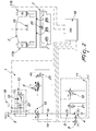
Figure 1 is a hydraulic diagram of a bending press that comprises an accumulator with a capacity of less than one liter, according to the present invention; -
Figure 2 is a hydraulic diagram of a bending press that comprises an accumulator with a capacity of more than one liter, according to the present invention; -
Figure 3 is a flowchart. - In the exemplary embodiments that follow, individual characteristics, given in relation to specific examples, may actually be interchanged with other different characteristics that exist in other exemplary embodiments.
- Moreover, it is noted that anything found to be already known during the patenting process is understood not to be claimed and to be the subject of a disclaimer.
- With reference to the previously cited figures, the
reference numeral 1 designates an active cambering device of bending presses comprising an upper beam 2 and alower beam 3. - In the accompanying drawings, some components have been designated by reference signs that are explained hereinafter:
- M1 = asynchronous motor
- P1 = pump
- V1 = pump discharge electric valve
- V2 = electric valve for accumulator discharge on safety block
- V3 = accumulator insertion electric valve
- V4 = safety valve on control unit
- V5 = one-way valve for pump protection
- V6 = circuit separation one-way valve
- V7 = accumulator oil side safety valve
- V8 = proportional direction valve
- V9 = safety valve
- BL1 = accumulator block
- BL2 = cambering block
- T I = pressure transducer
- ACC = accumulator(s)
- UT = position transducer on upper beam
- LT = position transducer on lower beam
- CNC = numeric control
- Y1 = left cylinder
- YY1 = left cylinder target level (level to which the left cylinder of the press must be brought in order to perform the set bending)
- Y2 = right cylinder
- YY2 = right cylinder target level (level to which the right cylinder of the press must be brought in order to perform the set bending)
- QUT = level detected by the transducer UT on upper beam
- QLT = level detected by the transducer LT on lower beam
- The device comprises a pump 4, P1 adapted to load at least one
accumulator 5, ACC, said accumulator being adapted to actuate saidlower beam 3 by means of a proportional direction valve 6, V8. - The position of the slider of the proportional direction valve 6, V8 is continuous and proportional to the current that flows through the coils/solenoids installed therein; in the specific case, the proportional direction valve 6, V8 has three possible positions between which the slider can move, affecting them both partially and completely.
- There is a first inactive position with closed centers, in which there is no connection between the various branches P (pressurized branch), T (discharge), A (use) and B (use) which arrive at/exit from the proportional direction valve 6, V8, which behaves like a plug, preventing the passage of the oil in any direction.
- There is a second position, designated by V8A, with crossed centers, in which the branch P is connected to the branch B; in this condition the oil flows toward the cambering
jacks 7 of thelower beam 3; the branch T is also connected to the branch A; in this condition, since A is plugged, nothing happens. - There is a third position, designated by V8B, with straight centers: the branch P is thus connected to the branch A (and since A is plugged, nothing happens) and the branch T is connected to the branch B: in this case the oil that arrives from the
cambering jacks 7 is discharged. - The pump 4, P1 is activated at power-on of the machine or press: in this step a
motor 8, M is switched on which, by rotating the pump 4, P1, starts to make the oil circulate in the circuit. - The oil flows through a
first valve 9, V5, which is a one-way valve for protecting the pump 4, P1; it is a one-way valve that prevents the flow of the oil toward the pump 4, P1 whereas it allows its flow toward the user device. - In this condition, the circuit is not pressurized, because the fluid is discharged through a first
electric valve 10, V1 that is in the inactive position. - The first
electric valve 10, V1 in the inactive position discharges the circuit onto thetank 11, whereas in the position V1A it prevents the passage of the oil toward thetank 11, i.e., it acts as a plug. - In order to pressurize the circuit, all the drains to the
tank 11 must be closed, and therefore the firstelectric valve 10, V1 is energized and reaches the position V1A and, if there is asafety block 12 foraccumulators 5, ACC, as shown inFigure 2 , a secondelectric valve 13, V2 also is energized which in turn reaches the position V2A. - The proportional direction valve 6, V8 is in the inactive position with the centers closed, i.e., with P, T, A and B plugged; the oil cannot pass through it and therefore the part of the circuit that is upstream thereof is pressurized.
- In the configuration of the preceding case, one achieves also the loading of the
accumulator 5, ACC, since thefirst valve 9, V5 and asecond valve 14, V5 and a thirdelectric valve 15, V3, the first two being simple one-way valves and the last one being a one-way valve in the inactive position, prevent the flow of the oil only downward; therefore, once the circuit is pressurized theaccumulator 5, ACC begins to load. - When a
pressure transducer 16, T1 sends the signal that the reference pressure (target) has been reached, the firstelectric valve 10, V1 is deactivated and the oil resumes flowing through it from the pump 4, P to thetank 11. - Due to the configuration of the third
electric valve 15, V3, which is inactive, theaccumulator 5, ACC remains pressurized. - Once the preparatory step for the power-on of the machine or press has ended, the bending cycle can begin; initially there is a quick descent of the upper beam 2 and then the step of approach to the metal plate to be bent (not shown) at the working speed begins.
- Shortly before the metal plate to be bent interacts with the
lower beam 3, the pump 4, P1 is inserted in the circuit again by activation of the firstelectric valve 10, V1, moving it to the position V1A. - One reaches a situation of equilibrium as regards the pressures, between the branches upstream and downstream of the third
electric valve 15, V3, which therefore can be in the position V3A so that the oil of theaccumulator 5, ACC can flow in the circuit; as long as this situation of pressure balance persists, nothing happens. - Upstream of the proportional direction valve 6, V8, which continues to remain inactive, the circuit is pressurized and the
accumulator 5, ACC is inserted. - The bending step begins and therefore following, deformation and cambering in position occur.
- The
main cylinders - As this step proceeds, the upper beam 2 is deformed; the numeric control or
computer 18, CNC begins comparing the values of the deformation of the upper beam 2 with those of thelower beam 3, measured respectively by adaptedposition transducers 19, UT and 20, LT, and operates accordingly; its purpose is to render the deflection of thelower beam 3 equal to the deflection of the upper beam 2. - To achieve this, the
cambering jacks - By moving toward the position V8A, the oil flows toward the
cambering jacks - By moving toward the position V8B, the cambering is depressurized and consequently the deformation of the lower
central beam 3 is reduced. - The numeric control or
computer 18, CNC operates therefore in the following manner: if the level QUT detected by thetransducer 19, UT on the upper beam 2 is higher than the level QLT detected by thetransducer 20, LT on thelower beam 3, the slider of the proportional direction valve 6, V8 is induced to move toward the position V8A and the deformation of thelower beam 3 is increased. - If instead QUT<QLT, the slider of the proportional direction valve 6, V8 is caused to move toward the position V8B and the deformation of the
lower beam 3 is decreased. - If QUT = QLT, the slider of the proportional direction valve 6, V8 is caused to move toward the inactive position and the deformation of the
lower beam 3 is kept constant. - All this occurs in a continuous and dynamic manner; as the two deflections mutually approach, the proportional direction valve 6, V8 approaches the central closure position; as the demand for oil decreases, the excess oil reloads the
accumulator 5, ACC. - Once the
main cylinders main cylinders - The upper beam 2 returns to the horizontal and therefore, since cambering is still active, the
lower beam 3, which continues to follow its deflection, also returns to the horizontal, discharging the excess oil from the cambering jacks 7. - Once the relaxation step has finished, with the upper beam 2 and the
lower beam 3 by now perfectly horizontal, the proportional direction valve 6, V8 is returned to the inactive position and one is ready to restart with a new bending cycle by reloading theaccumulators 5, ACC if necessary. - It is noted that in circuits with
accumulators 5, ACC of a capacity greater than one liter, and therefore with asafety block 12 certified according to the mandatory standards of the country of destination, once the machine or press has been powered on, the secondelectric valve 13, V2 remains always active (discharge closed) so that the oil cannot be discharged into thetank 11; it can be deactivated at the end of the day. - The maximum pressure in the circuit is determined first by the
third safety valve 21, V4 and then by thefourth safety valve 22, V7 and thefifth safety valve 23, V9. - The pressure of the
accumulator 5, ACC never drops below the minimum value necessary for cambering. - The proportional direction valve 6, V8 does not determine the pressure of the circuit, but merely passes either toward the cambering or toward the discharge quantities of oil that are proportional to the current that flows through the coils that move its slider.
- The first
electric valve 10, V1 and the thirdelectric valve 15, V3 are fundamentally on/off - open/closed valves; the thirdelectric valve 15, V3 actually always lets the oil flow 'upward from below', whereas it behaves as on-off only downward from above. - It is possible to provide for the use of
multiple accumulators 5, ACC with a capacity of less than one liter which are mutually connected. - In practice it has been found that the invention fully achieves the intended aim and objects cited above, more energy being saved than in the illustrated background art; the device allows moving small volumes of oil, but when it intervenes these volumes are supplied in very short times; there are, therefore, high flow-rates of oil and therefore many liters/minute.
- The use of the accumulator allows using a pump having a small capacity, despite supplying, in the set pressure range, high immediate flow-rates of oil.
- It is noted, moreover, that the device allows having the quantity of oil necessary only when it is needed, without draining it uselessly.
- Therefore, higher energy savings are achieved thanks to the use of the proportional direction valve 6, V8: in the background art the deformation of the jacks was controlled by a proportional pressure valve that operated this control, acting on the pressure of the circuit, but in order to do this large quantities of oil were drained and therefore large amounts of energy were 'wasted' uselessly.
- The device allows instead a position control by means of a proportional direction valve and therefore one drains and then produces the laminar flow of a quantity of oil that is positively lower than before, thus saving more energy.
- There is, moreover, a lower installed power: the main purpose of the pump 4, P1 is to charge the
accumulator 5, ACC during idle times, whereas the supply of the cambering jacks 7 is provided almost exclusively by the latter. - It is possible therefore to install a pump 4, P1 with a lower capacity than that of a circuit of the known type without accumulator.
- Finally, there is a higher speed of reaction of the cambering, due to the greater instantaneous flow supplied by the
accumulator 5, ACC and the use of the proportional direction valve 6, V8 with respect to the traditional circuit of the known type, where the function of supplying power to the cambering was performed by a larger pump and a proportional pressure valve was used. - With the device, the cycle time is reduced and productivity increases.
- The materials used, as well as the dimensions that constitute the individual components of the invention, may of course be more pertinent to the specific requirements.
- The various means for performing certain different functions need not certainly coexist only in the illustrated embodiment but can be present per se in many embodiments, including embodiments that are not illustrated.
- The characteristics indicated as advantageous, convenient or the like may also be omitted or be replaced with equivalents.
- The disclosures in
Italian Patent Application No. TV2012A000125 - Where technical features mentioned in any claim are followed by reference signs, those reference signs have been included for the sole purpose of increasing the intelligibility of the claims and accordingly such reference signs do not have any limiting effect on the interpretation of each element identified by way of example by such reference signs.
Claims (10)
- An active cambering device (1) of bending presses comprising an upper beam (2) and a lower beam (3), characterized in that it comprises a pump (4, P1) adapted to load at least one accumulator (5, ACC), said accumulator (5, ACC) being adapted to actuate said lower beam (3) by means of a proportional direction valve (6, V8).
- The device according to claim 1, characterized in that said proportional direction valve (6, V8) has a positioning of the slider that is continuous and proportional to the current that flows through the coils/solenoids installed therein, said proportional direction valve (6, V8) having three possible positions, between which said slider can move, affecting them both partially and completely: a first inactive position with closed centers, in which there is no connection between the various branches P (pressurized branch), T (discharge), A (use) and B (use) which arrive at/exit from said proportional direction valve (6, V8), which behaves like a plug, preventing the passage of the oil in any direction; a second position V8A with crossed centers, in which said branch P is connected to said branch B so that in this condition the oil flows toward the cambering jacks (7) of said lower beam (3) and said branch T is also connected to said branch A, which is plugged; a third position V8B with said centers straight, so as to connect said branch P to said plugged branch A, and said branch T to said branch B so as to discharge the oil that arrives form said cambering jacks (7).
- A method for active cambering of bending presses comprising an upper beam (2) and a lower beam (3), characterized in that once all the drains to a tank (11) are closed, in order to pressurize the circuit a first electric valve (10, V1) is energized and reaches the position V1A and, if a safety block (12) for at least one accumulator (5, ACC) is provided, a second electric valve (13, V2) also is energized and in turn reaches the position V2A, a proportional direction valve (6, V8) being provided in the inactive position with the branches (P, T, A, B) closed, allowing pressurization of the part of the circuit that is upstream thereof, achieving also the loading of said at least one accumulator (5, ACC) since a first valve (9, V5) and a second valve (14, V5) and a third electric valve (15, V3), the first two being simple one-way valves and the last one being a check valve in the inactive position, prevent the flow of the oil only downward, so that once the circuit is pressurized said at least one accumulator (5, ACC) begins to load.
- The method according to claim 3, characterized in that when a pressure transducer (16, T1) sends the signal that the reference pressure (target) has been reached, said first electric valve (10, V1) is deactivated and the oil resumes flowing through it from a pump (4, P) to said tank (11), the configuration of said third electric valve (15, V3) when inactive allowing said at least one accumulator (5, ACC) to remain pressurized.
- The method according to claim 3, wherein, once the preparatory step for the power-on of said bending press has ended, the bending cycle begins with an initial quick descent of said upper beam (2) and then a step of approach to the metal plate to be bent at the working speed, characterized in that shortly before said metal plate to be bent interacts with said lower beam (3), said pump (4, P1) is inserted in the circuit again by activating said first electric valve (10, V1), moving it to the position V1A so that a situation of equilibrium is reached as regards pressures between the branches upstream and downstream of said third electric valve (15, V3), which therefore can be in the position V3A so that the oil that is present in said at least one accumulator (5, ACC) can flow in the circuit.
- The method according to one or more of claims 3 to 5, characterized in that at the beginning of the bending step main cylinders (17a, 17b) of said upper beam (2) press downward in order to reach preset heights YY1 and YY2 which are adapted to allow reaching the target angle of the plate being bent as this step progresses, said upper beam (2) being deformed while a numeric control or computer (18, CNC) begins to compare the values of the deformation of said upper beam (2) with those of said lower beam (3), measured respectively by adapted position transducers (19, UT; 20, LT) in this step opening partially or fully said cambering jacks (17a, 17b) by acting on said proportional direction valve (6, V8), moving its slider continuously and proportionally to the supply current of the coils, between the positions V8A and V8B so that the deflection of said lower beam (3) matches the deflection of said upper beam (2).
- The method according to one or more of claims 3 to 6, characterized in that by moving toward said position V8A the oil flows toward said cambering jacks (17a, 17b), pressurizing them and opening them, whereas by moving toward said position V8B the cambering is depressurized and consequently the deformation of said lower beam (3) is reduced, said numeric control or computer (18, CNC) operating so that if the level (QOT) detected by said transducer (19, UT) on said upper beam (2) is higher than the level (QLT) detected by said transducer (20, LT) on said lower beam (3), the slider of said proportional direction valve (6, V() is caused to move toward said position V8A and the deformation of said lower beam (3) is increased; if instead QUT < QLT the slider of said proportional direction valve (6, V8) is caused to move toward said position V8B and the deformation of said lower beam (3) is decreased; if QUT = QLT the slider of said proportional direction valve (6, V8) is caused to move toward the inactive position and the deformation of said lower beam (3) is kept constant.
- The method according to one or more of claims 3 to 7, characterized in that as the two deflections mutually approach, said proportional direction valve (6, V8) approaches the central closure position, whereas as the demand for oil decreases, the excess oil reloads said at least one accumulator (5, ACC).
- The method according to one or more of claims 3 to 8, characterized in that once said main cylinders (17a, 17b) of said bending press have reached said levels YY1 and YY2 and the values of the deflections of said two beams, the lower one (3) and the upper one (2), are identical, the part has been bent and the relaxation step begins, in said step the pressure in said main cylinders (17a, 17b) being decreased and said upper beam (2) and said lower beam (3) returning to the horizontal, discharging the excess oil from said cambering jacks (7).
- The method according to one or more of claims 3 to 9, characterized in that the maximum pressure in the circuit is determined by a fourth safety valve (21, V4), by a fifth valve (22, V7) and by a sixth safety valve (23, V9), said proportional direction valve (6, V8) merely passing either toward the cambering or toward the discharge quantities of oil that are proportional to the current that flows through the coils that move the slider thereof.
Applications Claiming Priority (1)
| Application Number | Priority Date | Filing Date | Title |
|---|---|---|---|
| IT000125A ITTV20120125A1 (en) | 2012-07-06 | 2012-07-06 | DEVICE FOR BENDING IN FOLDING PRESSES. |
Publications (2)
| Publication Number | Publication Date |
|---|---|
| EP2682198A1 true EP2682198A1 (en) | 2014-01-08 |
| EP2682198B1 EP2682198B1 (en) | 2018-06-20 |
Family
ID=46758949
Family Applications (1)
| Application Number | Title | Priority Date | Filing Date |
|---|---|---|---|
| EP13163686.2A Active EP2682198B1 (en) | 2012-07-06 | 2013-04-15 | Cambering device in bending presses |
Country Status (2)
| Country | Link |
|---|---|
| EP (1) | EP2682198B1 (en) |
| IT (1) | ITTV20120125A1 (en) |
Cited By (1)
| Publication number | Priority date | Publication date | Assignee | Title |
|---|---|---|---|---|
| IT202400000804A1 (en) | 2024-01-17 | 2025-07-17 | Gasparini Ind S R L | PRESS BRAKE WITH ACTIVE CROWNING SYSTEM AND BENDING PROCEDURE WITH ACTIVE CROWNING SYSTEM. |
Citations (3)
| Publication number | Priority date | Publication date | Assignee | Title |
|---|---|---|---|---|
| US3914975A (en) * | 1970-12-25 | 1975-10-28 | Amada Co Ltd | Hydraulic press brake |
| US20070033981A1 (en) * | 2003-02-26 | 2007-02-15 | Gerrit Gerritsen | Method for correcting a folding operation and folding press |
| WO2008049796A1 (en) * | 2006-10-23 | 2008-05-02 | Task 84 S.P.A. | Process and device for measuring and controlling structural deflections of a pressing-bending machine |
Family Cites Families (6)
| Publication number | Priority date | Publication date | Assignee | Title |
|---|---|---|---|---|
| CH686119A5 (en) | 1991-10-31 | 1996-01-15 | Beyeler Raskin Sa | Method of adjustment of the slide stroke of a press brake and press brake with a tuning device for the implementation of the Method. |
| JP3317995B2 (en) | 1992-06-03 | 2002-08-26 | 株式会社アマダ | Processing control device for bending machine |
| JP3802176B2 (en) | 1997-01-27 | 2006-07-26 | 株式会社アマダエンジニアリングセンター | Deflection correction device for table in bending machine |
| IT1295498B1 (en) | 1997-10-17 | 1999-05-12 | Luciano Gasparini | DEVICE FOR DETECTING THE BENDING OF THE LOWER AND UPPER CROSSBARS, AIMED AT INTERACTION WITH AT LEAST ONE |
| US7079919B2 (en) | 2001-03-16 | 2006-07-18 | Bystronic Laser Ag | Method for setting the travel of a press brake |
| DE10155063A1 (en) | 2001-11-09 | 2003-05-22 | Wabco Gmbh & Co Ohg | Inductive displacement sensor, integrated in a hydraulic accumulator |
-
2012
- 2012-07-06 IT IT000125A patent/ITTV20120125A1/en unknown
-
2013
- 2013-04-15 EP EP13163686.2A patent/EP2682198B1/en active Active
Patent Citations (3)
| Publication number | Priority date | Publication date | Assignee | Title |
|---|---|---|---|---|
| US3914975A (en) * | 1970-12-25 | 1975-10-28 | Amada Co Ltd | Hydraulic press brake |
| US20070033981A1 (en) * | 2003-02-26 | 2007-02-15 | Gerrit Gerritsen | Method for correcting a folding operation and folding press |
| WO2008049796A1 (en) * | 2006-10-23 | 2008-05-02 | Task 84 S.P.A. | Process and device for measuring and controlling structural deflections of a pressing-bending machine |
Cited By (2)
| Publication number | Priority date | Publication date | Assignee | Title |
|---|---|---|---|---|
| IT202400000804A1 (en) | 2024-01-17 | 2025-07-17 | Gasparini Ind S R L | PRESS BRAKE WITH ACTIVE CROWNING SYSTEM AND BENDING PROCEDURE WITH ACTIVE CROWNING SYSTEM. |
| EP4588586A1 (en) | 2024-01-17 | 2025-07-23 | Gasparini Industries S.r.l. | Bending press with active crowning system and bending method with active crowning system |
Also Published As
| Publication number | Publication date |
|---|---|
| ITTV20120125A1 (en) | 2014-01-07 |
| EP2682198B1 (en) | 2018-06-20 |
Similar Documents
| Publication | Publication Date | Title |
|---|---|---|
| RU2683992C2 (en) | Hydraulic forging press and method of controlling such press | |
| CN205101299U (en) | Numerical control hydraulic pressure sheet material tubulation make -up machine hydraulic system | |
| CN207762060U (en) | A kind of overhead working truck system | |
| RU2459044C2 (en) | Load control hydraulic valve device | |
| US11407192B2 (en) | Hydraulic extrusion press and method for operating a hydraulic extrusion press | |
| US20200376527A1 (en) | Improved control of the water economy of a cooling path | |
| CN106351899B (en) | Auxiliary hydraulic system and pumping machine | |
| CN218717912U (en) | Accurate pressure control system in isostatic pressing machine pressure-increasing and pressure-reducing process | |
| EP2682198B1 (en) | Cambering device in bending presses | |
| US11358359B2 (en) | Hydraulic machine unit and method for operating such a machine unit | |
| CN102734237B (en) | Energy accumulator system and water pump system | |
| CN113883116A (en) | Oil drain valve, energy storage device, hydraulic system and operation machine | |
| RU2644443C1 (en) | Hydraulic system for loading of structures during strength tests | |
| US20250369458A1 (en) | Volume Follow Supply | |
| US20070137192A1 (en) | Circuit arrangement | |
| CN104930002A (en) | Hydraulic synchronous motor hydraulic console | |
| CN103111471B (en) | Dual-roll rolling machine hydraulic pressing down system and operation method thereof | |
| CN205089714U (en) | Pneumatic cylinder oil piping system of numerical control hydraulic pressure sheet material tubulation make -up machine | |
| CN204113776U (en) | A kind of energy-conservation second voltage regulation loop of hydraulic system | |
| CN107965482B (en) | Accurately controlled steel support prestress graded application system | |
| CN102803746A (en) | Arrangement for controlling the position of a device with a fluid pressure-driven piston-cylinder arrangement | |
| CN214742497U (en) | Proportional reversing valve control device of testing machine with different load control precision | |
| CN204572585U (en) | The hydraulic system of multi-position enclosed 4 Press Slider anti-bias loads | |
| RU2276237C2 (en) | Hydraulic system for mobile machine | |
| CN104265703B (en) | A kind of energy-conservation second voltage regulation loop of hydraulic system |
Legal Events
| Date | Code | Title | Description |
|---|---|---|---|
| PUAI | Public reference made under article 153(3) epc to a published international application that has entered the european phase |
Free format text: ORIGINAL CODE: 0009012 |
|
| AK | Designated contracting states |
Kind code of ref document: A1 Designated state(s): AL AT BE BG CH CY CZ DE DK EE ES FI FR GB GR HR HU IE IS IT LI LT LU LV MC MK MT NL NO PL PT RO RS SE SI SK SM TR |
|
| AX | Request for extension of the european patent |
Extension state: BA ME |
|
| RBV | Designated contracting states (corrected) |
Designated state(s): AL AT BE BG CH CY CZ DE DK EE ES FI FR GB GR HR HU IE IS IT LI LT LU LV MC MK MT NL NO PL PT RO RS SE SI SK SM TR |
|
| 17P | Request for examination filed |
Effective date: 20140626 |
|
| GRAP | Despatch of communication of intention to grant a patent |
Free format text: ORIGINAL CODE: EPIDOSNIGR1 |
|
| STAA | Information on the status of an ep patent application or granted ep patent |
Free format text: STATUS: GRANT OF PATENT IS INTENDED |
|
| INTG | Intention to grant announced |
Effective date: 20180116 |
|
| GRAS | Grant fee paid |
Free format text: ORIGINAL CODE: EPIDOSNIGR3 |
|
| GRAA | (expected) grant |
Free format text: ORIGINAL CODE: 0009210 |
|
| STAA | Information on the status of an ep patent application or granted ep patent |
Free format text: STATUS: THE PATENT HAS BEEN GRANTED |
|
| AK | Designated contracting states |
Kind code of ref document: B1 Designated state(s): AL AT BE BG CH CY CZ DE DK EE ES FI FR GB GR HR HU IE IS IT LI LT LU LV MC MK MT NL NO PL PT RO RS SE SI SK SM TR |
|
| REG | Reference to a national code |
Ref country code: GB Ref legal event code: FG4D |
|
| REG | Reference to a national code |
Ref country code: IE Ref legal event code: FG4D |
|
| REG | Reference to a national code |
Ref country code: AT Ref legal event code: REF Ref document number: 1010207 Country of ref document: AT Kind code of ref document: T Effective date: 20180715 |
|
| REG | Reference to a national code |
Ref country code: DE Ref legal event code: R096 Ref document number: 602013039101 Country of ref document: DE |
|
| REG | Reference to a national code |
Ref country code: NL Ref legal event code: MP Effective date: 20180620 |
|
| PG25 | Lapsed in a contracting state [announced via postgrant information from national office to epo] |
Ref country code: LT Free format text: LAPSE BECAUSE OF FAILURE TO SUBMIT A TRANSLATION OF THE DESCRIPTION OR TO PAY THE FEE WITHIN THE PRESCRIBED TIME-LIMIT Effective date: 20180620 Ref country code: NO Free format text: LAPSE BECAUSE OF FAILURE TO SUBMIT A TRANSLATION OF THE DESCRIPTION OR TO PAY THE FEE WITHIN THE PRESCRIBED TIME-LIMIT Effective date: 20180920 Ref country code: SE Free format text: LAPSE BECAUSE OF FAILURE TO SUBMIT A TRANSLATION OF THE DESCRIPTION OR TO PAY THE FEE WITHIN THE PRESCRIBED TIME-LIMIT Effective date: 20180620 Ref country code: FI Free format text: LAPSE BECAUSE OF FAILURE TO SUBMIT A TRANSLATION OF THE DESCRIPTION OR TO PAY THE FEE WITHIN THE PRESCRIBED TIME-LIMIT Effective date: 20180620 Ref country code: BG Free format text: LAPSE BECAUSE OF FAILURE TO SUBMIT A TRANSLATION OF THE DESCRIPTION OR TO PAY THE FEE WITHIN THE PRESCRIBED TIME-LIMIT Effective date: 20180920 |
|
| REG | Reference to a national code |
Ref country code: LT Ref legal event code: MG4D |
|
| PG25 | Lapsed in a contracting state [announced via postgrant information from national office to epo] |
Ref country code: LV Free format text: LAPSE BECAUSE OF FAILURE TO SUBMIT A TRANSLATION OF THE DESCRIPTION OR TO PAY THE FEE WITHIN THE PRESCRIBED TIME-LIMIT Effective date: 20180620 Ref country code: HR Free format text: LAPSE BECAUSE OF FAILURE TO SUBMIT A TRANSLATION OF THE DESCRIPTION OR TO PAY THE FEE WITHIN THE PRESCRIBED TIME-LIMIT Effective date: 20180620 Ref country code: GR Free format text: LAPSE BECAUSE OF FAILURE TO SUBMIT A TRANSLATION OF THE DESCRIPTION OR TO PAY THE FEE WITHIN THE PRESCRIBED TIME-LIMIT Effective date: 20180921 Ref country code: RS Free format text: LAPSE BECAUSE OF FAILURE TO SUBMIT A TRANSLATION OF THE DESCRIPTION OR TO PAY THE FEE WITHIN THE PRESCRIBED TIME-LIMIT Effective date: 20180620 |
|
| REG | Reference to a national code |
Ref country code: AT Ref legal event code: MK05 Ref document number: 1010207 Country of ref document: AT Kind code of ref document: T Effective date: 20180620 |
|
| PG25 | Lapsed in a contracting state [announced via postgrant information from national office to epo] |
Ref country code: NL Free format text: LAPSE BECAUSE OF FAILURE TO SUBMIT A TRANSLATION OF THE DESCRIPTION OR TO PAY THE FEE WITHIN THE PRESCRIBED TIME-LIMIT Effective date: 20180620 |
|
| PG25 | Lapsed in a contracting state [announced via postgrant information from national office to epo] |
Ref country code: IS Free format text: LAPSE BECAUSE OF FAILURE TO SUBMIT A TRANSLATION OF THE DESCRIPTION OR TO PAY THE FEE WITHIN THE PRESCRIBED TIME-LIMIT Effective date: 20181020 Ref country code: AT Free format text: LAPSE BECAUSE OF FAILURE TO SUBMIT A TRANSLATION OF THE DESCRIPTION OR TO PAY THE FEE WITHIN THE PRESCRIBED TIME-LIMIT Effective date: 20180620 Ref country code: EE Free format text: LAPSE BECAUSE OF FAILURE TO SUBMIT A TRANSLATION OF THE DESCRIPTION OR TO PAY THE FEE WITHIN THE PRESCRIBED TIME-LIMIT Effective date: 20180620 Ref country code: PL Free format text: LAPSE BECAUSE OF FAILURE TO SUBMIT A TRANSLATION OF THE DESCRIPTION OR TO PAY THE FEE WITHIN THE PRESCRIBED TIME-LIMIT Effective date: 20180620 Ref country code: CZ Free format text: LAPSE BECAUSE OF FAILURE TO SUBMIT A TRANSLATION OF THE DESCRIPTION OR TO PAY THE FEE WITHIN THE PRESCRIBED TIME-LIMIT Effective date: 20180620 Ref country code: RO Free format text: LAPSE BECAUSE OF FAILURE TO SUBMIT A TRANSLATION OF THE DESCRIPTION OR TO PAY THE FEE WITHIN THE PRESCRIBED TIME-LIMIT Effective date: 20180620 Ref country code: SK Free format text: LAPSE BECAUSE OF FAILURE TO SUBMIT A TRANSLATION OF THE DESCRIPTION OR TO PAY THE FEE WITHIN THE PRESCRIBED TIME-LIMIT Effective date: 20180620 |
|
| PG25 | Lapsed in a contracting state [announced via postgrant information from national office to epo] |
Ref country code: ES Free format text: LAPSE BECAUSE OF FAILURE TO SUBMIT A TRANSLATION OF THE DESCRIPTION OR TO PAY THE FEE WITHIN THE PRESCRIBED TIME-LIMIT Effective date: 20180620 Ref country code: SM Free format text: LAPSE BECAUSE OF FAILURE TO SUBMIT A TRANSLATION OF THE DESCRIPTION OR TO PAY THE FEE WITHIN THE PRESCRIBED TIME-LIMIT Effective date: 20180620 |
|
| REG | Reference to a national code |
Ref country code: DE Ref legal event code: R026 Ref document number: 602013039101 Country of ref document: DE |
|
| PLBI | Opposition filed |
Free format text: ORIGINAL CODE: 0009260 |
|
| PLAX | Notice of opposition and request to file observation + time limit sent |
Free format text: ORIGINAL CODE: EPIDOSNOBS2 |
|
| 26 | Opposition filed |
Opponent name: BYSTRONIC LASER AG Effective date: 20190320 |
|
| PG25 | Lapsed in a contracting state [announced via postgrant information from national office to epo] |
Ref country code: DK Free format text: LAPSE BECAUSE OF FAILURE TO SUBMIT A TRANSLATION OF THE DESCRIPTION OR TO PAY THE FEE WITHIN THE PRESCRIBED TIME-LIMIT Effective date: 20180620 |
|
| PLBB | Reply of patent proprietor to notice(s) of opposition received |
Free format text: ORIGINAL CODE: EPIDOSNOBS3 |
|
| PG25 | Lapsed in a contracting state [announced via postgrant information from national office to epo] |
Ref country code: SI Free format text: LAPSE BECAUSE OF FAILURE TO SUBMIT A TRANSLATION OF THE DESCRIPTION OR TO PAY THE FEE WITHIN THE PRESCRIBED TIME-LIMIT Effective date: 20180620 |
|
| REG | Reference to a national code |
Ref country code: DE Ref legal event code: R119 Ref document number: 602013039101 Country of ref document: DE |
|
| PG25 | Lapsed in a contracting state [announced via postgrant information from national office to epo] |
Ref country code: AL Free format text: LAPSE BECAUSE OF FAILURE TO SUBMIT A TRANSLATION OF THE DESCRIPTION OR TO PAY THE FEE WITHIN THE PRESCRIBED TIME-LIMIT Effective date: 20180620 |
|
| REG | Reference to a national code |
Ref country code: CH Ref legal event code: PL |
|
| REG | Reference to a national code |
Ref country code: BE Ref legal event code: MM Effective date: 20190430 |
|
| GBPC | Gb: european patent ceased through non-payment of renewal fee |
Effective date: 20190415 |
|
| PG25 | Lapsed in a contracting state [announced via postgrant information from national office to epo] |
Ref country code: LU Free format text: LAPSE BECAUSE OF NON-PAYMENT OF DUE FEES Effective date: 20190415 Ref country code: MC Free format text: LAPSE BECAUSE OF FAILURE TO SUBMIT A TRANSLATION OF THE DESCRIPTION OR TO PAY THE FEE WITHIN THE PRESCRIBED TIME-LIMIT Effective date: 20180620 |
|
| PG25 | Lapsed in a contracting state [announced via postgrant information from national office to epo] |
Ref country code: DE Free format text: LAPSE BECAUSE OF NON-PAYMENT OF DUE FEES Effective date: 20191101 Ref country code: LI Free format text: LAPSE BECAUSE OF NON-PAYMENT OF DUE FEES Effective date: 20190430 Ref country code: CH Free format text: LAPSE BECAUSE OF NON-PAYMENT OF DUE FEES Effective date: 20190430 Ref country code: GB Free format text: LAPSE BECAUSE OF NON-PAYMENT OF DUE FEES Effective date: 20190415 |
|
| PG25 | Lapsed in a contracting state [announced via postgrant information from national office to epo] |
Ref country code: BE Free format text: LAPSE BECAUSE OF NON-PAYMENT OF DUE FEES Effective date: 20190430 Ref country code: FR Free format text: LAPSE BECAUSE OF NON-PAYMENT OF DUE FEES Effective date: 20190430 |
|
| PG25 | Lapsed in a contracting state [announced via postgrant information from national office to epo] |
Ref country code: TR Free format text: LAPSE BECAUSE OF FAILURE TO SUBMIT A TRANSLATION OF THE DESCRIPTION OR TO PAY THE FEE WITHIN THE PRESCRIBED TIME-LIMIT Effective date: 20180620 |
|
| PG25 | Lapsed in a contracting state [announced via postgrant information from national office to epo] |
Ref country code: IE Free format text: LAPSE BECAUSE OF NON-PAYMENT OF DUE FEES Effective date: 20190415 |
|
| PG25 | Lapsed in a contracting state [announced via postgrant information from national office to epo] |
Ref country code: PT Free format text: LAPSE BECAUSE OF FAILURE TO SUBMIT A TRANSLATION OF THE DESCRIPTION OR TO PAY THE FEE WITHIN THE PRESCRIBED TIME-LIMIT Effective date: 20181022 |
|
| PLAB | Opposition data, opponent's data or that of the opponent's representative modified |
Free format text: ORIGINAL CODE: 0009299OPPO |
|
| R26 | Opposition filed (corrected) |
Opponent name: BYSTRONIC LASER AG Effective date: 20190320 |
|
| PG25 | Lapsed in a contracting state [announced via postgrant information from national office to epo] |
Ref country code: CY Free format text: LAPSE BECAUSE OF FAILURE TO SUBMIT A TRANSLATION OF THE DESCRIPTION OR TO PAY THE FEE WITHIN THE PRESCRIBED TIME-LIMIT Effective date: 20180620 |
|
| PG25 | Lapsed in a contracting state [announced via postgrant information from national office to epo] |
Ref country code: HU Free format text: LAPSE BECAUSE OF FAILURE TO SUBMIT A TRANSLATION OF THE DESCRIPTION OR TO PAY THE FEE WITHIN THE PRESCRIBED TIME-LIMIT; INVALID AB INITIO Effective date: 20130415 Ref country code: MT Free format text: LAPSE BECAUSE OF FAILURE TO SUBMIT A TRANSLATION OF THE DESCRIPTION OR TO PAY THE FEE WITHIN THE PRESCRIBED TIME-LIMIT Effective date: 20180620 |
|
| PLCK | Communication despatched that opposition was rejected |
Free format text: ORIGINAL CODE: EPIDOSNREJ1 |
|
| APBM | Appeal reference recorded |
Free format text: ORIGINAL CODE: EPIDOSNREFNO |
|
| APBP | Date of receipt of notice of appeal recorded |
Free format text: ORIGINAL CODE: EPIDOSNNOA2O |
|
| APAH | Appeal reference modified |
Free format text: ORIGINAL CODE: EPIDOSCREFNO |
|
| APBQ | Date of receipt of statement of grounds of appeal recorded |
Free format text: ORIGINAL CODE: EPIDOSNNOA3O |
|
| PG25 | Lapsed in a contracting state [announced via postgrant information from national office to epo] |
Ref country code: MK Free format text: LAPSE BECAUSE OF FAILURE TO SUBMIT A TRANSLATION OF THE DESCRIPTION OR TO PAY THE FEE WITHIN THE PRESCRIBED TIME-LIMIT Effective date: 20180620 |
|
| REG | Reference to a national code |
Ref country code: DE Ref legal event code: R100 Ref document number: 602013039101 Country of ref document: DE |
|
| APBU | Appeal procedure closed |
Free format text: ORIGINAL CODE: EPIDOSNNOA9O |
|
| PLBN | Opposition rejected |
Free format text: ORIGINAL CODE: 0009273 |
|
| STAA | Information on the status of an ep patent application or granted ep patent |
Free format text: STATUS: OPPOSITION REJECTED |
|
| 27O | Opposition rejected |
Effective date: 20230220 |
|
| PGFP | Annual fee paid to national office [announced via postgrant information from national office to epo] |
Ref country code: IT Payment date: 20260407 Year of fee payment: 14 |