EP2682075A1 - Stent delivery system - Google Patents
Stent delivery system Download PDFInfo
- Publication number
- EP2682075A1 EP2682075A1 EP12752266.2A EP12752266A EP2682075A1 EP 2682075 A1 EP2682075 A1 EP 2682075A1 EP 12752266 A EP12752266 A EP 12752266A EP 2682075 A1 EP2682075 A1 EP 2682075A1
- Authority
- EP
- European Patent Office
- Prior art keywords
- stent
- rotary roller
- delivery system
- outer tube
- housing
- Prior art date
- Legal status (The legal status is an assumption and is not a legal conclusion. Google has not performed a legal analysis and makes no representation as to the accuracy of the status listed.)
- Withdrawn
Links
- 230000006835 compression Effects 0.000 claims description 3
- 238000007906 compression Methods 0.000 claims description 3
- 238000003780 insertion Methods 0.000 claims description 3
- 230000037431 insertion Effects 0.000 claims description 3
- 230000033001 locomotion Effects 0.000 abstract description 24
- 230000005540 biological transmission Effects 0.000 abstract description 5
- 230000000717 retained effect Effects 0.000 description 12
- 230000003902 lesion Effects 0.000 description 11
- 239000007788 liquid Substances 0.000 description 11
- 239000000463 material Substances 0.000 description 5
- 210000004204 blood vessel Anatomy 0.000 description 3
- 239000003550 marker Substances 0.000 description 3
- 229910045601 alloy Inorganic materials 0.000 description 2
- 239000000956 alloy Substances 0.000 description 2
- 238000011010 flushing procedure Methods 0.000 description 2
- 239000011347 resin Substances 0.000 description 2
- 229920005989 resin Polymers 0.000 description 2
- 210000000013 bile duct Anatomy 0.000 description 1
- 230000000694 effects Effects 0.000 description 1
- 230000005489 elastic deformation Effects 0.000 description 1
- 210000003238 esophagus Anatomy 0.000 description 1
- KHYBPSFKEHXSLX-UHFFFAOYSA-N iminotitanium Chemical compound [Ti]=N KHYBPSFKEHXSLX-UHFFFAOYSA-N 0.000 description 1
- 239000007769 metal material Substances 0.000 description 1
- 229910001000 nickel titanium Inorganic materials 0.000 description 1
- 230000000149 penetrating effect Effects 0.000 description 1
- 239000002504 physiological saline solution Substances 0.000 description 1
- 230000000630 rising effect Effects 0.000 description 1
- 210000003437 trachea Anatomy 0.000 description 1
- 210000003708 urethra Anatomy 0.000 description 1
Images




Classifications
-
- A—HUMAN NECESSITIES
- A61—MEDICAL OR VETERINARY SCIENCE; HYGIENE
- A61F—FILTERS IMPLANTABLE INTO BLOOD VESSELS; PROSTHESES; DEVICES PROVIDING PATENCY TO, OR PREVENTING COLLAPSING OF, TUBULAR STRUCTURES OF THE BODY, e.g. STENTS; ORTHOPAEDIC, NURSING OR CONTRACEPTIVE DEVICES; FOMENTATION; TREATMENT OR PROTECTION OF EYES OR EARS; BANDAGES, DRESSINGS OR ABSORBENT PADS; FIRST-AID KITS
- A61F2/00—Filters implantable into blood vessels; Prostheses, i.e. artificial substitutes or replacements for parts of the body; Appliances for connecting them with the body; Devices providing patency to, or preventing collapsing of, tubular structures of the body, e.g. stents
- A61F2/95—Instruments specially adapted for placement or removal of stents or stent-grafts
- A61F2/962—Instruments specially adapted for placement or removal of stents or stent-grafts having an outer sleeve
- A61F2/966—Instruments specially adapted for placement or removal of stents or stent-grafts having an outer sleeve with relative longitudinal movement between outer sleeve and prosthesis, e.g. using a push rod
-
- A—HUMAN NECESSITIES
- A61—MEDICAL OR VETERINARY SCIENCE; HYGIENE
- A61F—FILTERS IMPLANTABLE INTO BLOOD VESSELS; PROSTHESES; DEVICES PROVIDING PATENCY TO, OR PREVENTING COLLAPSING OF, TUBULAR STRUCTURES OF THE BODY, e.g. STENTS; ORTHOPAEDIC, NURSING OR CONTRACEPTIVE DEVICES; FOMENTATION; TREATMENT OR PROTECTION OF EYES OR EARS; BANDAGES, DRESSINGS OR ABSORBENT PADS; FIRST-AID KITS
- A61F2/00—Filters implantable into blood vessels; Prostheses, i.e. artificial substitutes or replacements for parts of the body; Appliances for connecting them with the body; Devices providing patency to, or preventing collapsing of, tubular structures of the body, e.g. stents
- A61F2/02—Prostheses implantable into the body
- A61F2/04—Hollow or tubular parts of organs, e.g. bladders, tracheae, bronchi or bile ducts
- A61F2/06—Blood vessels
- A61F2/07—Stent-grafts
-
- A—HUMAN NECESSITIES
- A61—MEDICAL OR VETERINARY SCIENCE; HYGIENE
- A61F—FILTERS IMPLANTABLE INTO BLOOD VESSELS; PROSTHESES; DEVICES PROVIDING PATENCY TO, OR PREVENTING COLLAPSING OF, TUBULAR STRUCTURES OF THE BODY, e.g. STENTS; ORTHOPAEDIC, NURSING OR CONTRACEPTIVE DEVICES; FOMENTATION; TREATMENT OR PROTECTION OF EYES OR EARS; BANDAGES, DRESSINGS OR ABSORBENT PADS; FIRST-AID KITS
- A61F2/00—Filters implantable into blood vessels; Prostheses, i.e. artificial substitutes or replacements for parts of the body; Appliances for connecting them with the body; Devices providing patency to, or preventing collapsing of, tubular structures of the body, e.g. stents
- A61F2/95—Instruments specially adapted for placement or removal of stents or stent-grafts
- A61F2/9517—Instruments specially adapted for placement or removal of stents or stent-grafts handle assemblies therefor
Definitions
- the present invention relates to a stent delivery system for delivering and indwelling a stent into a lumen of a living body such as a blood vessel.
- a stent which is formed in the shape of a hollow cylinder having a multiplicity of openings in its side wall from a metallic wire or the like and which can be expanded in a lumen of a living body, such as a blood vessel, bile duct, trachea, esophagus and urethra, is used for improvement of a lesion part (stenosed part or obliterated part) generated in the lumen of the living body.
- a stent delivery system in which the stent is delivered into a living body in the state of being compressed and contained in a gap between an inner tube and an outer tube, and then the outer tube is retracted proximally so as to release the stent, whereby the stent is put indwelling in the lesion part.
- the above-mentioned stent delivery system has an operating mechanism for displacing the outer tube in an axial direction relative to the inner tube.
- a gear rack is meshed with a gear of a rotatable wheel, and the outer tube is connected to an end portion of the gear rack. With the wheel rotated in a predetermined direction, the gear rack is advanced and retracted in the axial direction so as to move the outer tube relative to the inner tube, whereby the stent is released to the exterior of the outer tube.
- the gear rack and the outer tube connected to the gear rack can be moved in the axial direction attendantly on the rotation of the wheel. Therefore, in the case where the outer tube is caught in the lesion part in a lumen of a living body or the like so that movement of the outer tube in the axial direction is made difficult, for example, if an operator continues to forcibly rotate the wheel, the gear rack and the outer tube are forcibly pulled in the axial direction. This is attended by exertion of an excessive load on the stent delivery system (especially, on the outer tube). As a result, the stent delivery system would be broken, so that a broken component part of the stent delivery system may be left in the lumen of the living body.
- a stent delivery system including: an inner tube; a stent which is compressed toward a center axis and disposed on a distal-side outer surface of the inner tube at the time of insertion into a lumen of a living body and which can be restored into its pre-compression shape by expanding outward when put indwelling in the lumen of the living body; an outer tube which is disposed on an outer surface side of the inner tube, can contain the stent in its lumen, and can release the stent to the exterior by moving proximally relative to the inner tube; and an operating unit for moving the outer tube in an axial direction relative to the inner tube.
- the operating unit includes: a housing; a rotary body which is so supported as to be rotatable relative to the housing and which has a first tooth portion; a rack body which has a second tooth portion meshed with the first tooth portion, is so disposed as to be movable in the axial direction relative to the housing, and is connected to the outer tube; and a releasing mechanism by which meshing between the rotary body and the rack body is released when a load of not less than a predetermined value is exerted on either one of the rotary body and the rack body.
- the operating unit by which the outer tube disposed on the outer surface side of the inner tube is moved in the axial direction includes: the housing; the rotary body supported so as to be rotatable relative to the housing and having the first tooth portion; and the rack body having the second tooth portion meshed with the first tooth portion, being movable in the axial direction relative to the housing, and being connected to the outer tube.
- the operating unit is provided with the releasing mechanism by which meshing between the rotary body and the rack body can be released when a load of not less than a predetermined value is exerted on either one of the rotary body and the rack body.
- the releasing mechanism ensures that when a load of not less than a predetermined value is exerted on the rotary body or the rack body, the meshed state of the first tooth portion of the rotary body and the second tooth portion of the rack body is released. In such a case, therefore, transmission of the rotating force of the rotary body to the rack body is prevented from occurring. Accordingly, a situation in which the rack body and the outer tube would be forcibly pulled in the axial direction is obviated. As a result, each component constituting the stent delivery system can be securely prevented from being broken due to exertion of an excessive load, so that a situation in which, for example, a broken part would be left in a living body lumen can be avoided.
- reference symbol 10 denotes a stent delivery system of a first embodiment according to the present invention.
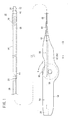
- this stent delivery system 10 includes: an inner tube body (inner tube) 12 formed in a tubular shape; an outer tube body (outer tube) 14 disposed on the outer circumference side of the inner tube body 12; an expandable stent 16 contained between the inner tube body 12 and the outer tube body 14; and an operating unit 18 for moving the outer tube body 14 in relation to the inner tube body 12.
- proximal end (rear end) the left side of the inner tube body 12 and the outer tube body 14
- distal end the right side of the inner tube body 12 and the outer tube body 14
- distal end direction of arrow B
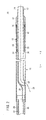
- the inner tube body 12 includes: a first distal tube 24 formed therein with a guide wire lumen 22 in which to insert and pass a guide wire 20 (see FIG. 2 ); a first proximal tube 28 connected through a connecting member 26 to the proximal side (the direction of arrow A) of the first distal tube 24; and a connector 30 connected to the proximal end of the first proximal tube 28.
- This inner tube body 12 is composed of tubular bodies, in which the distal ends and proximal ends of the first distal tube 24 and the first proximal tube 28 are opening respectively, and the distal end of the first distal tube 24 is so disposed as to protrude beyond the distal end of the outer tube body 14.
- the above-mentioned guide wire 20 is used, for example, for guiding the stent delivery system 10 to a lesion part in a lumen of a living body.
- the inner tube body 12 has a structure in which the proximal end of the first distal tube 24 and the distal end of the first proximal tube 28 are connected to each other, through the connecting member 26, inside the outer tube body 14.
- the first proximal tube 28 has a lumen 32 penetrating therethrough from the distal end to the proximal end thereof.
- a liquid such as physiological saline is injected via the connector 30.
- the first distal tube 24 is formed from a highly flexible resin material
- the first proximal tube 28 is formed from a high-strength metallic material.
- the first distal tube 24 is provided with a stent holding mechanism 34 which functions at the time of re-containing the stent 16 having been released to the exterior of the outer tube body 14 to an intermediate extent.
- the stent holding mechanism 34 disposed on the outer circumferential surface of the inner tube body 12 includes a stent locking part 36 and a stent engaging part 38.
- the stent locking part 36 is disposed at a position located on the proximal side (the direction of arrow A) of the stent 16 when the stent 16 is contained in the inside of the outer tube body 14.
- the stent engaging part 38 is disposed on the distal side (the direction of arrow B) of the first distal tube 24 relative to the stent locking part 36, and a reduced diameter section 40 of the stent 16 to be described later is engaged with the stent engaging part 38.
- the stent locking part 36 and the stent engaging part 38 are each formed in an annular shape, they protrude toward the radially outer side which is the outer tube body 14 side, and they are arranged with a predetermined spacing therebetween along an axial direction of the first distal tube 24 (in the direction of arrows A and B).
- the height of the stent engaging part 38 is set smaller than the height of the stent locking part 36.
- the proximal end of the stent 16 makes contact with the stent locking part 36, whereby the stent 16 is expanded in the state of being positioned in a predetermined position.
- the reduced diameter section 40 makes contact with the stent engaging part 38, whereby the stent 16 is retained in the state of being positioned in a predetermined position.
- a stopper part 42 which bulges radially outward and which restricts distal movement of the outer tube body 14. This ensures that the outer tube body 14 is inhibited from protruding in the axial direction (in the direction of arrow B) relative to the distal end of the inner tube body 12.
- the proximal end of the first distal tube 24 is gently curved toward the radially outer side of the first distal tube 24, and communicates with a guide wire leading-out hole 44 of the outer tube body 14.
- the connector 30 is formed in a hollow cylindrical shape, is connected to and communicates with the first proximal tube 28 of the inner tube body 12, and is so formed as to permit connection thereto of a liquid injector (e.g., syringe) which is not shown.
- a liquid injector e.g., syringe
- the liquid injector is connected to the connector 30, a liquid is injected through the lumen 32 of the first proximal tube 28, and the liquid flows to the distal ends of the inner tube body 12 and the outer tube body 14, whereby the inside of the tube bodies can be flushed.
- the outer tube body 14 is composed of tubular bodies; specifically, it includes a second distal tube 46 in which the first distal tube 24 of the inner tube body 12 is disposed, and a second proximal tube 48 which is connected to the proximal side (the direction of arrow A) of the second distal tube 46 and in which the first proximal tube 28 is disposed.
- the distal end of the second distal tube 46 functions as a release port at the time of indwelling the stent 16 into a lesion part of a lumen of a living body, and functions also as a containing port at the time of containing the stent 16 having been released to an intermediate extent.
- the guide wire leading-out hole 44 so opened as to establish communication between the inner lumen of the second distal tube 46 and the exterior.
- the guide wire leading-out hole 44 is so provided that it can communicate with the opening of the guide wire lumen 22 of the first distal tube 24 provided inside the second distal tube 46.
- the guide wire 20 inserted and passed in the guide wire lumen 22 of the inner tube body 12 can be led out to the exterior.
- a contrast marker 50 is disposed on the outer circumferential surface of the second distal tube 46.
- the contrast marker 50 is formed in an annular shape from a radiopaque material, for example.
- the stent 16 is formed in the shape of a substantially cylindrical mesh having a multiplicity of openings.
- the stent 16 is a self-expandable stent which is disposed inside the second distal tube 46 of the outer tube body 14 in the state of being compressed toward the radially inner side (toward the center axis) at the time of insertion into a lumen of a living body, and which, by being released via the distal end of the outer tube body 14 into a lesion part in the lumen of the living body, can be expanded radially outward to be restored into its pre-compression shape.
- the material constituting the stent 16 is preferably a superelastic alloy such as Ni-Ti alloy, for example.
- contrast markers 52a and 52b each formed in an annular shape from a radiopaque material, for example.
- the reduced diameter section 40 which is reduced radially inward is formed at the proximal end of the stent 16. The reduced diameter section 40 is so formed as not to make contact with the outer circumferential surface of the inner tube body 12.
- the operating unit 18 includes: a housing 54; a rack member (rack body) 56 contained inside the housing 54 and connected to the outer tube body 14; and a rotary roller 60 which has a first gear 58 meshed with the rack member 56 and by which the rack member 56 is displaced rectilinearly.
- the housing 54 is round-shaped at its central portion, and is composed of a first housing 62 and a second housing 64 into which the housing 54 is bisected at the center in the thickness direction thereof.
- the housing 54 is provided, inside the first and second housings 62 and 64, with a roller containing section 66 capable of containing the rotary roller 60 in a roughly central portion thereof. Part of the rotary roller 60 is exposed to the exterior through a roller hole 68 formed in the roller containing section 66.
- the roller containing section 66 is provided with a curved wall 70 projecting from an inner wall surface of the first housing 62 toward the second housing 64.
- the curved wall 70 is formed in an arcuate sectional shape curved toward the radially outer side (in the direction of arrow C1 in FIG. 8A ) with the axis of the rotary roller 60 as a center (of a circle) and with a predetermined radius.
- the curved wall 70 is disposed downward relative to rotary shafts 74 of the rotary roller 60.
- the curved wall 70 is formed over the range of a predetermined center angle about the rotary shafts 74.
- the rotary roller 60 is rotatably supported by a pair of bearings 72 formed at inner wall surfaces of the first and second housings 62 and 64.
- the bearings 72 are recessed in relation to the inner wall surfaces of the first and second housings 62 and 64, and are formed in the shape of oblong holes which are elongated in the vertical direction (in the directions of arrows D1 and D2) orthogonal to the axial direction (the directions of arrows A and B) of the first and second housings 62 and 64.
- the rotary roller 60 is supported so as to be movable in the vertical direction (in the directions of arrows D1 and D2) through the rotary shafts 74 supported by the bearings 72.
- the second housing 64 is formed therein with first and second containing grooves 76 and 78 in which the rack member 56 is contained and retained so as to be movable in the axial direction (in the directions of arrows A and B).
- the first containing groove 76 is provided on the proximal side (the direction of arrow A) in the second housing 64, while the second containing groove 78 is provided on the distal side (the direction of arrow B) in the second housing 64.
- the roller containing section 66 is disposed between the first containing groove 76 and the second containing groove 78.
- the rack member 56 is retained by the first and second containing grooves 76 and 78 in the state of being movable rectilinearly toward the distal side and the proximal side.
- a connector containing section 80 in which to contain the connector 30 is formed on the proximal side (the direction of arrow A) relative to the first containing groove 76.
- the connector 30 is fixed to the housing 54 by being contained in the connector containing section 80.
- the proximal end of the first proximal tube 28 constituting the inner tube body 12 is fixed to the operating unit 18 through the connector 30.
- the connector containing section 80 is opening toward the proximal side (in the direction of arrow A) of the housing 54, and is so formed that the liquid injector (not shown) can be connected to the connector 30 from the exterior of the housing 54.
- a distal nozzle 82 by which the second proximal tube 48 of the outer tube body 14 is slidably retained is mounted on the distal end of the housing 54.
- the distal nozzle 82 is formed therein with a through-hole (not shown) in which the second proximal tube 48 is inserted and passed.
- a cap 84 is screw-engaged onto the distal end of the housing 54, whereby the distal nozzle 82 is fixed.
- the outer tube body 14, with the inner tube body 12 inserted and passed therein is inserted into the housing 54 through the distal nozzle 82, and is connected to the rack member 56.
- the rack member 56 is composed of a pair of first and second blocks 86 and 88 which are formed in straight and substantially symmetric shapes.
- the proximal end of the second proximal tube 48 of the outer tube body 14 is fixed by being clamped between the first block 86 and the second block 88.
- the rack member 56 composed of the first and second blocks 86 and 88 is inserted in the first and second containing grooves 76 and 78 inside the housing 54, whereby the rack member 56 is retained in the state of being rectilinearly movable toward the distal side and the proximal side of the housing 54.
- the first block 86 is provided inside the housing 54 so as to front on the rotary roller 60, and its side surface fronting on the rotary roller 60 is provided with a plurality of first tooth portions 90 defined by projections and recesses arranged along the axial direction (the direction of arrows A and B).
- the rotary roller 60 includes a main body 92 having the pair of rotary shafts 74, and an annular section 94 spaced radially outward from the main body 92 and exposed to the exterior through the roller hole 68.
- the main body 92 and the annular section 94 are formed to be approximately equal in width.
- the main body 92 is formed in a cylindrical shape, and is provided at its center with the pair of rotary shafts 74 projecting in mutually spaced directions.
- the rotary shafts 74 are inserted in the bearings 72 of the first and second housings 62 and 64, respectively.
- first gear 58 having a plurality of second tooth portions 96 in radially outward direction, with the rotary shafts 74 as a center, is provided at a side surface of the main body 92, and is meshed with the first tooth portions 90 of the rack member 56.
- the rack member 56 With the rotary roller 60 rotated, the rack member 56 is moved rectilinearly along the first and second containing grooves 76 and 78.
- the operating unit 18 is provided with a releasing mechanism 100 by which meshing between the rotary roller 60 and the rack member 56 is released in the case where the outer tube body 14 comes to be unmovable relative to the inner tube body 12 and a load G of not less than a predetermined value is exerted on the rotary roller 60.
- the releasing mechanism 100 includes: a support body 104 which is arcuate in sectional shape and which is provided in a space 102 between the main body 92 and the annular section 94; and a resilient member 106 which is provided between the support body 104 and the curved wall 70 and which biases the support body 104 toward the main body 92.
- the curved wall 70 is also disposed inside the space 102.
- the support body 104 is so disposed as to make sliding contact with the outer circumferential surface of the main body 92.
- the support body 104 is so formed as to have an inside diameter approximately equal to the outside diameter of the main body 92 and have a predetermined thickness; besides, the support body 104 faces the curved wall 70 and is disposed coaxially with the curved wall 70 and the rotary roller 60.
- the resilient member 106 is composed, for example, of a plurality of coil springs, which are arranged at intervals along the outer circumferential surface of the support body 104, and are constantly biasing the support body 104 toward the rotary roller 60, or radially inward (in the direction of arrow C2).
- the resilient force of the resilient member 106 is appropriately set so that the pressure with which the support body 104 is pressed toward the rotary roller 60 (in the direction of arrow C2) will be a predetermined pressure. The setting of the resilient force will be described later.
- the support body 104 is so supported as to be freely movable toward and away from the curved wall 70 through the resilient member 106.
- a leaf spring, a resin material, a rubber and the like may also be used in place of the coil springs.
- the inner circumferential surface of the support body 104 is constantly making sliding contact with the outer circumferential surface of the main body 92 under resiliency of the resilient member 106, thereby pressing the main body 92 radially inward (in the direction of arrow C2).
- the rotary roller 60 is rotatably retained in the condition in which the rotary shafts 74 are located upward (the direction of arrow D1) inside the bearings 72.
- the first gear 58 (the rotary roller 60) is being biased toward the rack member 56, and the rotary roller 60 and the rack member 56 are in a meshed state.
- the operator rotates the annular section 94 of the rotary roller 60 in a predetermined direction (in the direction of arrow E) relative to the housing 54, as shown in FIG. 6 .
- the rack member 56 inside the housing 54 is moved along the first and second containing grooves 76 and 78 toward the connector 30 (in the direction of arrow A), attended by movement (retraction) of the outer tube body 14 toward the proximal side of the housing 54.
- the stent 16 is released via the distal end of the outer tube body 14.
- the rack member 56 is moved along the first and second containing grooves 76 and 78 in the direction for spacing away from the connector 30 (in the direction of arrow B). This is attended by movement (advancement) of the outer tube body 14 toward the distal side relative to the inner tube body 12, whereby the stent 16 is re-contained into the inside of the outer tube body 14.
- the operating unit 18 is provided with a locking mechanism 108 by which a moving motion of the rack member 56 can be restricted through restriction of a rotating motion of the rotary roller 60.
- the locking mechanism 108 includes: a slide member 112 which is provided at a hole part 110 opening in a side surface of the first housing 62 so that it can be displaced by sliding; and a pin groove 114 formed in a side surface of the main body 92 of the rotary roller 60 so as to front on the slide member 112.
- the slide member 112 is so retained as to be rectilinearly displaceable toward the distal and proximal sides (in the directions of arrows A and B) of the first housing 62 through the hole part 110.
- the rack member 56 is prevented from moving in the axial direction, and, attendantly, a forward or backward movement of the outer tube body 14 is restricted.
- the operating unit 18 is provided with an intermittent mechanism 118 for putting the rotary roller 60 into intermittent rotation.
- the intermittent mechanism 118 includes: a second gear 120 disposed at a side surface, opposite to the first gear 58, of the rotary roller 60; and a notch member 122 retained by the second housing 64 and engaged with a tooth portion of the second gear 120.
- the notch member 122 is formed in the shape of an elastically deformable thin sheet, for example. The notch member 122 extends from a part retained by the second housing 64 toward the center of the second gear 120, and is engaged with the tooth portion of the second gear 120.
- the notch member 122 engaged with the second gear 120 is elastically deformed, to being disengaged from a recess of the tooth portion and come over a projection adjacent to the recess, thereby being again engaged with another recess.
- This enables an intermittent rotating motion.
- it is also possible to confirm the rotating motion and/or a rotational angle of the rotary roller 60.
- the stent delivery system 10 of the first embodiment according to the present invention is basically configured as above-described. Now, the operation and effect of the stent delivery system 10 will be described below. Incidentally, a state is assumed in which the guide wire 20 is inserted in a lumen of a living body (for example, a blood vessel), and its distal end has preliminarily been put indwelling in a lesion part in the lumen of the living body.
- a living body for example, a blood vessel
- flushing of the stent delivery system 10 shown in FIG. 1 is conducted.
- the operator connects a liquid injector (not shown) to the connector 30 disposed at the proximal end of the operating unit 18, and injects a liquid from the liquid injector into the connector 30.
- the liquid flows to the distal side of the inner tube body 12 and the outer tube body 14 (in the direction of arrow B).
- the liquid having reached the distal end is ejected from the distal ends of the inner tube body 12 and the outer tube body 14, whereby flushing of the inside of the inner tube body 12 and the outer tube body 14 is completed in the exterior of a living body.
- the proximal end of the guide wire 20 exposed to the exterior of the living body is inserted and passed via the distal end of the inner tube body 12 into the guide wire lumen 22, and the inner tube body 12 and the outer tube body 14 are gradually advanced along the guide wire 20 into the lumen of the living body.
- the proximal end of the guide wire 20 is led out to the exterior of the outer tube body 14 through the guide wire leading-out hole 44.
- the slide member 112 of the operating unit 18 is moved toward the distal side (in the direction of arrow B), and the pin 116 is disengaged from the pin groove 114 of the rotary roller 60, whereby the restriction imposed on rotation of the rotary roller 60 is removed. Then, the rotary roller 60 is rotated in a predetermined direction (in the direction of arrow E).
- the rack member 56 is moved proximally (in the direction of arrow A) within the housing 54. This is attended by gradual movement of the outer tube body 14 toward the proximal side of the operating unit 18.
- the stent 16 contained in the outer tube body 14 starts being gradually exposed, starting from its distal portion; simultaneously, the stent 16 starts being expanded radially outward. Then, the stent 16 comes into the state of being completely exposed from the outer tube body 14, whereby the stent 16 is put indwelling in the lesion part in the state of being expanded in the cylindrical shape.
- the rotary roller 60 of the operating unit 18 is rotated so as to gradually move the outer tube body 14 toward the proximal side (in the direction of arrow A).
- the outer tube body 14 may be caught at the lesion part in the lumen of the living body, making it difficult to move the outer tube body 14 proximally.
- the load G exerted on the rotary roller 60 causes the second tooth portion 96 of the first gear 58 to run onto the first tooth portion 90 of the rack member 56, and the rotary roller 60 is pressed down radially outward (in the direction of arrow C1) while compressing the resilient member 106 through the support body 104.
- the rotary roller 60 is moved by a predetermined distance in the vertically downward direction (in the direction of arrow D2) along the bearings 72 in which the rotary shafts 74 are inserted. Consequently, the first gear 58 of the rotary roller 60 and the first tooth portion 90 of the rack member 56 are put into a non-meshed state, so that transmission of the rotating force of the rotary roller 60 to the rack member 56 is avoided.
- the second tooth portion 96 of the rotary roller 60 comes over the first tooth portion 90 of the rack member 56, and the rotary roller 60 is moved radially outward against the resilience of the resilient member 106, to be put into a non-meshed state, namely, the state of being out of mesh with the rack member 56.
- the load G is appropriately set according to the resilient force of the resilient member 106.
- the load G is set on the basis of a lowest-yield-point part of such components as the outer tube body 14, the inner tube body 12, the operating unit 18, etc. constituting the stent delivery system 10.
- the load G is set on the basis of the lowest yield point of the components of the stent delivery system 10, and the resilient member 106 having a resilient force approximately equal to or lower than the load G is disposed between the curved wall 70 and the support body 104, thereby biasing the rotary roller 60 upward (toward the rack member 56 side).
- This ensures that when the load G is applied to the rotary roller 60, the rotary roller 60 is so moved as to be separated from the rack member 56, so that the meshing between them is released, and exertion of a further load on the rack member 56 is avoided. Therefore, the lowest-yield-point component in the stent delivery system 10 is prevented from being plastically deformed beyond its yield point, and breakage of the component is securely prevented.
- the releasing mechanism 100 is provided by which meshing between the rotary roller 60 and the rack member 56 constituting the operating unit 18 can be released. This ensures that, even in the case where axial movement of the rack member 56 and the outer tube body 14 connected to the rack member 56 becomes difficult for some reason, when a load G of not less than a predetermined value is exerted on the rotary roller 60, the rotary roller 60 can go down in the direction for spacing from the rack member 56, and thereby to put the rotary roller 60 and the rack member 56 into a non-meshed state.
- FIGS. 10A and 10B a stent delivery system 150 of a second embodiment according to the present invention is shown in FIGS. 10A and 10B .
- the same components as those of the stent delivery system 10 according to the first embodiment described above will be denoted by the same reference symbols as used above, and detailed descriptions thereof will be omitted.
- the stent delivery system 150 of the second embodiment differs from the stent delivery system 10 of the first embodiment in that a rack member 154 constituting an operating unit 152 is formed to be hollow and that a first block 156 meshed with the first gear 58 is freely bendable.
- the rack member 154 has a structure in which first and second blocks 156 and 158 are formed therein with an inner cavity 160, and the inner cavity 160 extends in the axial direction of the rack member 154 while having a substantially constant height.
- the first block 156 is freely bendable in a direction in which the first tooth portion 90 is spaced away from the first gear 58 of the rotary roller 60. More specifically, the first block 156 is so formed that its bottom surface having the first tooth portion 90 is freely bendable upward (in the direction of arrow D1) through the inner cavity 160.
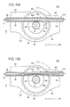
- a load G of not less than a predetermined value is exerted on the rotary roller 60 radially outward (in the direction of arrow C1) and upward (in the direction of arrow D1) due to the rotation of the rotary roller 60, as shown in FIG. 10B .
- the load G is set on the basis of a lowest-yield-point component of such components as the outer tube body 14, the inner tube body 12, the operating unit 152, etc. constituting the stent delivery system 150. Then, the second tooth portion 96 of the first gear 58 runs onto the first tooth portion 90 of the rack member 154 of which movement is restricted, and the first block 156 of the rack member 154 is deformed so as to be bent toward the second block 158 (in the direction of arrow D1).
- the first block 156 is elastically deformed upward so as to become arcuate in sectional shape, with its part meshed with the first gear 58 as a center, and comes into the inner cavity 160.
- This deformation of the first block 156 results in a non-meshed state in which meshing between the first gear 58 and the rack member 154 has been released, so that transmission of the rotating force of the rotary roller 60 to the rack member 154 is obviated.
- the first block 156 constituting the rack member 154 may be so configured that it is plastically deformed when the second tooth portion 96 of the first gear 58 runs onto the first tooth portion 90 and when it is bent upward (in the direction of arrow D1). In this case, the first block 156 is retained in the state of being bent upward, so that its first tooth portion 90 is perfectly prevented from being meshed with the first gear 58. Consequently, the meshed state is prevented from being established again.
- the rack member 154 having therein with the inner cavity 160 functions as a releasing mechanism 162 by which the meshed state of the rotary roller 60 and the rack member 154 constituting the operating unit 152 can be released.
- the rack member 154 constituting the releasing mechanism 162 is formed to be freely deformable in the direction for spacing away from the first gear 58 of the rotary roller 60 when a load G of not less than a predetermined value is exerted on the rotary roller 60 radially outward (in the direction of arrow C1) and upward (in the direction of arrow D1). It is ensured that, when such a load G is exerted, the first block 156 is bent in the direction for spacing away from the first gear 58 (in the direction of arrow D1), and the meshing between the rotary roller 60 and the rack member 154 is released.
- FIGS. 11A and 11B a stent delivery system 200 of a third embodiment according to the present invention is shown in FIGS. 11A and 11B .
- the same components as those of the stent delivery systems 10 and 150 of the first and second embodiments described above are denoted by the same reference symbols as used above, and detailed descriptions thereof will be omitted.
- the stent delivery system 200 of the third embodiment differs from the stent delivery systems 10 and 150 of the first and second embodiments in that an elastic member 204 capable of elastic deformation is disposed between the rack member 56 constituting an operating unit 202 and inner wall surfaces of the first and second containing grooves 76 and 78 so that the rack member 56 can be moved upward by compressing the elastic member 204.
- the elastic member 204 is formed, for example, from a rubber or the like, in a plate-like shape with a substantially uniform thickness, and has a predetermined resilient force in the thickness direction thereof.
- the elastic member 204 is mounted between a top surface of the second block 88 constituting the rack member 56 and the inner wall surfaces of the first and second containing gooves 76 and 78.
- a load G of not less than a predetermined value is exerted on the rotary roller 60 radially outward (in the direction of arrow C1) and upward (in the direction of arrow D1) due to the rotation of the rotary roller 60, as shown in FIG. 11B .
- the load G is set on the basis of a lowest-yield-point component of such components as the outer tube body 14, the inner tube body 12, the operating unit 202, etc. constituting the stent delivery system 200.
- the second tooth portion 96 of the first gear 58 runs onto the first tooth portion 90 of the rack member 56, of which movement is restricted, and the rack member 56 is pressed upward (in the direction of arrow D1) so as to rise against the resilient force of the elastic member 204.
- the rising of the rack member 56 results in a non-meshed state in which meshing between the first gear 58 and the rack member 56 has been released, so that transmission of the rotating force of the rotary roller 60 to the rack member 56 is avoided.
- the rack member 56 is provided in the housing 54 in the state of being movable upward (in the direction of arrow D1) through the elastic member 204, and the elastic member 204 and the rack member 56 function as a releasing mechanism 206 by which the meshed state of the rotary roller 60 and the rack member 56 constituting the operating unit 202 can be released.
- the rack member 56 is so provided as to be freely movable in the direction for spacing away from the first gear 58 of the rotary roller 60 (in the direction of arrow D1) relative to the housing 54. This ensures that, when a load G of not less than a predetermined value is exerted on the rotary roller 60 radially outward (in the direction of arrow C1) and upward (in the direction of arrow D1), the rack member 56 is moved in the direction for spacing away from the first gear 58 (in the direction of arrow D1) against the resilient force of the elastic member 204 disposed on the upper side thereof, and the meshing between the rotary roller 60 and the rack member 56 is released.
- the stent delivery system according to the present invention is not restricted to the above-described embodiments, and, naturally, various configurations are possible without departure from the gist of the invention.
Landscapes
- Health & Medical Sciences (AREA)
- Engineering & Computer Science (AREA)
- Biomedical Technology (AREA)
- Heart & Thoracic Surgery (AREA)
- Oral & Maxillofacial Surgery (AREA)
- Transplantation (AREA)
- Cardiology (AREA)
- Vascular Medicine (AREA)
- Life Sciences & Earth Sciences (AREA)
- Animal Behavior & Ethology (AREA)
- General Health & Medical Sciences (AREA)
- Public Health (AREA)
- Veterinary Medicine (AREA)
- Pulmonology (AREA)
- Gastroenterology & Hepatology (AREA)
- Media Introduction/Drainage Providing Device (AREA)
Abstract
Description
- The present invention relates to a stent delivery system for delivering and indwelling a stent into a lumen of a living body such as a blood vessel.
- Conventionally, there have been cases where a stent which is formed in the shape of a hollow cylinder having a multiplicity of openings in its side wall from a metallic wire or the like and which can be expanded in a lumen of a living body, such as a blood vessel, bile duct, trachea, esophagus and urethra, is used for improvement of a lesion part (stenosed part or obliterated part) generated in the lumen of the living body.
- In connection with the case of a self-expandable stent in which the stent itself has a self-expanding function, for example, there has been known a stent delivery system in which the stent is delivered into a living body in the state of being compressed and contained in a gap between an inner tube and an outer tube, and then the outer tube is retracted proximally so as to release the stent, whereby the stent is put indwelling in the lesion part.
- As disclosed in
JP-T-2007-504897 - In the stent delivery system having the operating mechanism as above-mentioned, however, the gear rack and the outer tube connected to the gear rack can be moved in the axial direction attendantly on the rotation of the wheel. Therefore, in the case where the outer tube is caught in the lesion part in a lumen of a living body or the like so that movement of the outer tube in the axial direction is made difficult, for example, if an operator continues to forcibly rotate the wheel, the gear rack and the outer tube are forcibly pulled in the axial direction. This is attended by exertion of an excessive load on the stent delivery system (especially, on the outer tube). As a result, the stent delivery system would be broken, so that a broken component part of the stent delivery system may be left in the lumen of the living body.
- It is a general object of the present invention to provide a stent delivery system by which breakage due to exertion of an excessive load when movement of the outer tube becomes difficult can be prevented from occurring.
- According to the present invention, there is provided a stent delivery system including: an inner tube; a stent which is compressed toward a center axis and disposed on a distal-side outer surface of the inner tube at the time of insertion into a lumen of a living body and which can be restored into its pre-compression shape by expanding outward when put indwelling in the lumen of the living body; an outer tube which is disposed on an outer surface side of the inner tube, can contain the stent in its lumen, and can release the stent to the exterior by moving proximally relative to the inner tube; and an operating unit for moving the outer tube in an axial direction relative to the inner tube. The operating unit includes: a housing; a rotary body which is so supported as to be rotatable relative to the housing and which has a first tooth portion; a rack body which has a second tooth portion meshed with the first tooth portion, is so disposed as to be movable in the axial direction relative to the housing, and is connected to the outer tube; and a releasing mechanism by which meshing between the rotary body and the rack body is released when a load of not less than a predetermined value is exerted on either one of the rotary body and the rack body.
- According to the present invention, in the stent delivery system for putting a stent indwelling in a lesion part in a lumen of a living body, the operating unit by which the outer tube disposed on the outer surface side of the inner tube is moved in the axial direction includes: the housing; the rotary body supported so as to be rotatable relative to the housing and having the first tooth portion; and the rack body having the second tooth portion meshed with the first tooth portion, being movable in the axial direction relative to the housing, and being connected to the outer tube. The operating unit is provided with the releasing mechanism by which meshing between the rotary body and the rack body can be released when a load of not less than a predetermined value is exerted on either one of the rotary body and the rack body.
- Therefore, even in the case where axial movement of the rack body and the outer tube connected to the rack body becomes difficult for some reason and the operator forcibly rotates the rotary body, the releasing mechanism ensures that when a load of not less than a predetermined value is exerted on the rotary body or the rack body, the meshed state of the first tooth portion of the rotary body and the second tooth portion of the rack body is released. In such a case, therefore, transmission of the rotating force of the rotary body to the rack body is prevented from occurring. Accordingly, a situation in which the rack body and the outer tube would be forcibly pulled in the axial direction is obviated. As a result, each component constituting the stent delivery system can be securely prevented from being broken due to exertion of an excessive load, so that a situation in which, for example, a broken part would be left in a living body lumen can be avoided.
-
- [
FIG. 1 ]
FIG. 1 is a general configuration view of a stent delivery system of a first embodiment according to the present invention. - [
FIG. 2 ]
FIG. 2 is a partly omitted sectional view showing an inner tube body and an outer tube body of the stent delivery system shown inFIG. 1 . - [
FIG. 3 ]
FIG. 3 is an enlarged sectional view showing the vicinity of distal ends of the inner tube body and the outer tube body shown inFIG. 2 . - [
FIG. 4 ]
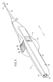
FIG. 4 is an external appearance perspective view of an operating unit constituting the stent delivery system shown inFIG. 1 . - [
FIG. 5 ]
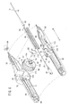
FIG. 5 is an exploded perspective view of the operating unit shown inFIG. 4 . - [
FIG. 6 ]
FIG. 6 is a side view of the inside of the operating unit shown inFIGS. 4 and5 . - [
FIG. 7 ]
FIG. 7 is an enlarged sectional view showing a state in which a stent is released from the distal end of the outer tube body to an intermediate extent, or a case in which the stent released to an intermediate extent is containd into the inside of the outer tube body. - [
FIG. 8 ]
FIG. 8A is a partly omitted enlarged view showing the vicinity of a rotary roller and a rack member shown inFIG. 6 , andFIG. 8B is a cross-sectional view taken along line VIIIB-VIIIB ofFIG. 8A . - [
FIG. 9 ]
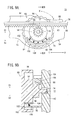
FIG. 9A is a partly omitted enlarged view showing a non-meshed state in which the rotary roller shown inFIG. 8 goes down in a direction for spacing away from the rack member, andFIG. 9B is a cross-sectional view taken along line IXB-IXB ofFIG. 9A . - [
FIG. 10 ]
FIG. 10A is an enlarged view showing the vicinity of a rotary roller and a rack member in an operating unit of a stent delivery system of a second embodiment according to the present invention, andFIG. 10B is an enlarged view showing a non-meshed state in which the rack member ofFIG. 10A is bent upward to be spaced from a first gear. - [
FIG. 11 ]
FIG. 11A is an enlarged view showing the vicinity of a rotary roller and a rack member in an operating unit of a stent delivery system of a third embodiment according to the present invention, andFIG. 11B is an enlarged view showing a non-meshed state in which the rack member ofFIG. 11A has been moved in a direction for spacing away from the first gear while compressing an elastic member. - In
FIG. 1 ,reference symbol 10 denotes a stent delivery system of a first embodiment according to the present invention. - As shown in
FIG. 1 , thisstent delivery system 10 includes: an inner tube body (inner tube) 12 formed in a tubular shape; an outer tube body (outer tube) 14 disposed on the outer circumference side of theinner tube body 12; anexpandable stent 16 contained between theinner tube body 12 and theouter tube body 14; and anoperating unit 18 for moving theouter tube body 14 in relation to theinner tube body 12. - Incidentally, in
FIG. 1 , the left side of theinner tube body 12 and theouter tube body 14 is referred to as "proximal end (rear end)" side (direction of arrow A), and the right side of theinner tube body 12 and theouter tube body 14 is referred to as "distal end" side (direction of arrow B), the same applying also to the other figures. - As shown in
FIGS. 1 to 3 , theinner tube body 12 includes: a firstdistal tube 24 formed therein with aguide wire lumen 22 in which to insert and pass a guide wire 20 (seeFIG. 2 ); a firstproximal tube 28 connected through a connectingmember 26 to the proximal side (the direction of arrow A) of the firstdistal tube 24; and aconnector 30 connected to the proximal end of the firstproximal tube 28. - This
inner tube body 12 is composed of tubular bodies, in which the distal ends and proximal ends of the firstdistal tube 24 and the firstproximal tube 28 are opening respectively, and the distal end of thefirst distal tube 24 is so disposed as to protrude beyond the distal end of theouter tube body 14. Incidentally, the above-mentionedguide wire 20 is used, for example, for guiding thestent delivery system 10 to a lesion part in a lumen of a living body. - The
inner tube body 12 has a structure in which the proximal end of thefirst distal tube 24 and the distal end of the firstproximal tube 28 are connected to each other, through the connectingmember 26, inside theouter tube body 14. In addition, the firstproximal tube 28 has alumen 32 penetrating therethrough from the distal end to the proximal end thereof. Into thelumen 32, a liquid such as physiological saline is injected via theconnector 30. Incidentally, it is preferable that the firstdistal tube 24 is formed from a highly flexible resin material, and the firstproximal tube 28 is formed from a high-strength metallic material. - The first
distal tube 24 is provided with astent holding mechanism 34 which functions at the time of re-containing thestent 16 having been released to the exterior of theouter tube body 14 to an intermediate extent. As shown inFIG. 3 , thestent holding mechanism 34 disposed on the outer circumferential surface of theinner tube body 12 includes astent locking part 36 and astent engaging part 38. Thestent locking part 36 is disposed at a position located on the proximal side (the direction of arrow A) of thestent 16 when thestent 16 is contained in the inside of theouter tube body 14. Thestent engaging part 38 is disposed on the distal side (the direction of arrow B) of the firstdistal tube 24 relative to thestent locking part 36, and a reduceddiameter section 40 of thestent 16 to be described later is engaged with thestent engaging part 38. - The
stent locking part 36 and thestent engaging part 38 are each formed in an annular shape, they protrude toward the radially outer side which is theouter tube body 14 side, and they are arranged with a predetermined spacing therebetween along an axial direction of the first distal tube 24 (in the direction of arrows A and B). Incidentally, the height of thestent engaging part 38 is set smaller than the height of thestent locking part 36. - This ensures that in a state in which the
stent 16 is contained inside theouter tube body 14, its proximal end makes contact with thestent locking part 36, and the reduceddiameter section 40 is retained between thestent locking part 36 and thestent engaging part 38, whereby thestent 16 is retained in such a position as not to be exposed to the exterior through the distal end of theouter tube body 14. - Incidentally, at the time when the
stent 16 is released via the distal end of theouter tube body 14, the proximal end of thestent 16 makes contact with thestent locking part 36, whereby thestent 16 is expanded in the state of being positioned in a predetermined position. In addition, at the time when thestent 16 having been released to an intermediate extent is re-contained into the inside of theouter tube body 14, the reduceddiameter section 40 makes contact with thestent engaging part 38, whereby thestent 16 is retained in the state of being positioned in a predetermined position. - Besides, at the distal end of the first
distal tube 24, there is formed astopper part 42 which bulges radially outward and which restricts distal movement of theouter tube body 14. This ensures that theouter tube body 14 is inhibited from protruding in the axial direction (in the direction of arrow B) relative to the distal end of theinner tube body 12. - On the other hand, the proximal end of the first
distal tube 24 is gently curved toward the radially outer side of the firstdistal tube 24, and communicates with a guide wire leading-out hole 44 of theouter tube body 14. - As shown in
FIGS. 4 to 6 , theconnector 30 is formed in a hollow cylindrical shape, is connected to and communicates with the firstproximal tube 28 of theinner tube body 12, and is so formed as to permit connection thereto of a liquid injector (e.g., syringe) which is not shown. In a state in which the liquid injector is connected to theconnector 30, a liquid is injected through thelumen 32 of the firstproximal tube 28, and the liquid flows to the distal ends of theinner tube body 12 and theouter tube body 14, whereby the inside of the tube bodies can be flushed. - As shown in
FIGS. 1 to 3 , theouter tube body 14 is composed of tubular bodies; specifically, it includes a seconddistal tube 46 in which the firstdistal tube 24 of theinner tube body 12 is disposed, and a secondproximal tube 48 which is connected to the proximal side (the direction of arrow A) of the seconddistal tube 46 and in which the firstproximal tube 28 is disposed. Incidentally, the distal end of the seconddistal tube 46 functions as a release port at the time of indwelling thestent 16 into a lesion part of a lumen of a living body, and functions also as a containing port at the time of containing thestent 16 having been released to an intermediate extent. - In addition, on the proximal side of the second
distal tube 46, there is formed the guide wire leading-out hole 44 so opened as to establish communication between the inner lumen of the seconddistal tube 46 and the exterior. The guide wire leading-out hole 44 is so provided that it can communicate with the opening of theguide wire lumen 22 of the firstdistal tube 24 provided inside the seconddistal tube 46. Through the guide wire leading-out hole 44, theguide wire 20 inserted and passed in theguide wire lumen 22 of theinner tube body 12 can be led out to the exterior. - Furthermore, at a distal portion of the second
distal tube 46, acontrast marker 50 is disposed on the outer circumferential surface of the seconddistal tube 46. Thecontrast marker 50 is formed in an annular shape from a radiopaque material, for example. - The
stent 16 is formed in the shape of a substantially cylindrical mesh having a multiplicity of openings. Thestent 16 is a self-expandable stent which is disposed inside the seconddistal tube 46 of theouter tube body 14 in the state of being compressed toward the radially inner side (toward the center axis) at the time of insertion into a lumen of a living body, and which, by being released via the distal end of theouter tube body 14 into a lesion part in the lumen of the living body, can be expanded radially outward to be restored into its pre-compression shape. Incidentally, the material constituting thestent 16 is preferably a superelastic alloy such as Ni-Ti alloy, for example. - Besides, at the distal end and the proximal end of the
stent 16, there aredisposed contrast markers diameter section 40 which is reduced radially inward is formed at the proximal end of thestent 16. The reduceddiameter section 40 is so formed as not to make contact with the outer circumferential surface of theinner tube body 12. - As shown in
FIGS. 1 and4 to6 , the operatingunit 18 includes: ahousing 54; a rack member (rack body) 56 contained inside thehousing 54 and connected to theouter tube body 14; and arotary roller 60 which has afirst gear 58 meshed with therack member 56 and by which therack member 56 is displaced rectilinearly. - The
housing 54 is round-shaped at its central portion, and is composed of afirst housing 62 and asecond housing 64 into which thehousing 54 is bisected at the center in the thickness direction thereof. Thehousing 54 is provided, inside the first andsecond housings roller containing section 66 capable of containing therotary roller 60 in a roughly central portion thereof. Part of therotary roller 60 is exposed to the exterior through aroller hole 68 formed in theroller containing section 66. - As shown in
FIGS. 5 ,8 and9 , theroller containing section 66 is provided with acurved wall 70 projecting from an inner wall surface of thefirst housing 62 toward thesecond housing 64. Thecurved wall 70 is formed in an arcuate sectional shape curved toward the radially outer side (in the direction of arrow C1 inFIG. 8A ) with the axis of therotary roller 60 as a center (of a circle) and with a predetermined radius. Thecurved wall 70 is disposed downward relative torotary shafts 74 of therotary roller 60. Incidentally, thecurved wall 70 is formed over the range of a predetermined center angle about therotary shafts 74. - In addition, the
rotary roller 60 is rotatably supported by a pair ofbearings 72 formed at inner wall surfaces of the first andsecond housings bearings 72 are recessed in relation to the inner wall surfaces of the first andsecond housings second housings rotary roller 60 is supported so as to be movable in the vertical direction (in the directions of arrows D1 and D2) through therotary shafts 74 supported by thebearings 72. - Besides, the
second housing 64 is formed therein with first and second containinggrooves rack member 56 is contained and retained so as to be movable in the axial direction (in the directions of arrows A and B). The first containinggroove 76 is provided on the proximal side (the direction of arrow A) in thesecond housing 64, while the second containinggroove 78 is provided on the distal side (the direction of arrow B) in thesecond housing 64. Theroller containing section 66 is disposed between the first containinggroove 76 and the second containinggroove 78. - With the
first housing 62 and thesecond housing 64 combined with each other, therack member 56 is retained by the first and second containinggrooves - In addition, a
connector containing section 80 in which to contain theconnector 30 is formed on the proximal side (the direction of arrow A) relative to the first containinggroove 76. Theconnector 30 is fixed to thehousing 54 by being contained in theconnector containing section 80. As a result, the proximal end of the firstproximal tube 28 constituting theinner tube body 12 is fixed to the operatingunit 18 through theconnector 30. - Incidentally, the
connector containing section 80 is opening toward the proximal side (in the direction of arrow A) of thehousing 54, and is so formed that the liquid injector (not shown) can be connected to theconnector 30 from the exterior of thehousing 54. - On the other hand, a
distal nozzle 82 by which the secondproximal tube 48 of theouter tube body 14 is slidably retained is mounted on the distal end of thehousing 54. Thedistal nozzle 82 is formed therein with a through-hole (not shown) in which the secondproximal tube 48 is inserted and passed. In the condition in which thedistal nozzle 82 is mounted on the distal end of thehousing 54, acap 84 is screw-engaged onto the distal end of thehousing 54, whereby thedistal nozzle 82 is fixed. In other words, theouter tube body 14, with theinner tube body 12 inserted and passed therein, is inserted into thehousing 54 through thedistal nozzle 82, and is connected to therack member 56. - The
rack member 56 is composed of a pair of first andsecond blocks proximal tube 48 of theouter tube body 14 is fixed by being clamped between thefirst block 86 and thesecond block 88. - The
rack member 56 composed of the first andsecond blocks grooves housing 54, whereby therack member 56 is retained in the state of being rectilinearly movable toward the distal side and the proximal side of thehousing 54. - Besides, the
first block 86 is provided inside thehousing 54 so as to front on therotary roller 60, and its side surface fronting on therotary roller 60 is provided with a plurality offirst tooth portions 90 defined by projections and recesses arranged along the axial direction (the direction of arrows A and B). - The
rotary roller 60 includes amain body 92 having the pair ofrotary shafts 74, and anannular section 94 spaced radially outward from themain body 92 and exposed to the exterior through theroller hole 68. Themain body 92 and theannular section 94 are formed to be approximately equal in width. Themain body 92 is formed in a cylindrical shape, and is provided at its center with the pair ofrotary shafts 74 projecting in mutually spaced directions. Therotary shafts 74 are inserted in thebearings 72 of the first andsecond housings - In addition, the
first gear 58 having a plurality ofsecond tooth portions 96 in radially outward direction, with therotary shafts 74 as a center, is provided at a side surface of themain body 92, and is meshed with thefirst tooth portions 90 of therack member 56. With therotary roller 60 rotated, therack member 56 is moved rectilinearly along the first and second containinggrooves - The operating
unit 18 is provided with a releasingmechanism 100 by which meshing between therotary roller 60 and therack member 56 is released in the case where theouter tube body 14 comes to be unmovable relative to theinner tube body 12 and a load G of not less than a predetermined value is exerted on therotary roller 60. - The releasing
mechanism 100 includes: asupport body 104 which is arcuate in sectional shape and which is provided in aspace 102 between themain body 92 and theannular section 94; and aresilient member 106 which is provided between thesupport body 104 and thecurved wall 70 and which biases thesupport body 104 toward themain body 92. Incidentally, thecurved wall 70 is also disposed inside thespace 102. - The
support body 104 is so disposed as to make sliding contact with the outer circumferential surface of themain body 92. For example, thesupport body 104 is so formed as to have an inside diameter approximately equal to the outside diameter of themain body 92 and have a predetermined thickness; besides, thesupport body 104 faces thecurved wall 70 and is disposed coaxially with thecurved wall 70 and therotary roller 60. - The
resilient member 106 is composed, for example, of a plurality of coil springs, which are arranged at intervals along the outer circumferential surface of thesupport body 104, and are constantly biasing thesupport body 104 toward therotary roller 60, or radially inward (in the direction of arrow C2). In addition, the resilient force of theresilient member 106 is appropriately set so that the pressure with which thesupport body 104 is pressed toward the rotary roller 60 (in the direction of arrow C2) will be a predetermined pressure. The setting of the resilient force will be described later. - In other words, the
support body 104 is so supported as to be freely movable toward and away from thecurved wall 70 through theresilient member 106. Incidentally, as the above-mentionedresilient member 106, a leaf spring, a resin material, a rubber and the like may also be used in place of the coil springs. - As a result of this, the inner circumferential surface of the
support body 104 is constantly making sliding contact with the outer circumferential surface of themain body 92 under resiliency of theresilient member 106, thereby pressing themain body 92 radially inward (in the direction of arrow C2). As shown inFIG. 8A , therefore, therotary roller 60 is rotatably retained in the condition in which therotary shafts 74 are located upward (the direction of arrow D1) inside thebearings 72. In addition, the first gear 58 (the rotary roller 60) is being biased toward therack member 56, and therotary roller 60 and therack member 56 are in a meshed state. - In the above-mentioned
operating unit 18, for example, the operator rotates theannular section 94 of therotary roller 60 in a predetermined direction (in the direction of arrow E) relative to thehousing 54, as shown inFIG. 6 . By this operation, therack member 56 inside thehousing 54 is moved along the first and second containinggrooves outer tube body 14 toward the proximal side of thehousing 54. As a result, thestent 16 is released via the distal end of theouter tube body 14. - On the other hand, when the
rotary roller 60 is rotated in the opposite direction to the above-mentioned (in the direction of arrow F) after thestent 16 is released to an intermediate extent, therack member 56 is moved along the first and second containinggrooves outer tube body 14 toward the distal side relative to theinner tube body 12, whereby thestent 16 is re-contained into the inside of theouter tube body 14. - Besides, as shown in
FIG. 6 , the operatingunit 18 is provided with alocking mechanism 108 by which a moving motion of therack member 56 can be restricted through restriction of a rotating motion of therotary roller 60. - The
locking mechanism 108 includes: aslide member 112 which is provided at ahole part 110 opening in a side surface of thefirst housing 62 so that it can be displaced by sliding; and apin groove 114 formed in a side surface of themain body 92 of therotary roller 60 so as to front on theslide member 112. Theslide member 112 is so retained as to be rectilinearly displaceable toward the distal and proximal sides (in the directions of arrows A and B) of thefirst housing 62 through thehole part 110. - When a
pin 116 rectangular in sectional shape projecting into the inside of thefirst housing 62 is inserted into thepin groove 114 of therotary roller 60, in the condition where theslide member 112 is located on the proximal side of thehousing 54, a rotating motion of therotary roller 60 is restricted. - Therefore, the
rack member 56 is prevented from moving in the axial direction, and, attendantly, a forward or backward movement of theouter tube body 14 is restricted. - In addition, with the
slide member 112 moved toward the distal side of the housing 54 (in the direction of arrow B), thepin 116 is disengaged from thepin groove 114 toward the radially outer side of therotary roller 60. Therefore, the restriction of rotation of therotary roller 60 by thepin 116 is removed, resulting in a state in which therack member 56 can be moved in the axial direction (in the directions of arrows A and B) under the rotating action of therotary roller 60. - Furthermore, the operating
unit 18 is provided with anintermittent mechanism 118 for putting therotary roller 60 into intermittent rotation. Theintermittent mechanism 118 includes: asecond gear 120 disposed at a side surface, opposite to thefirst gear 58, of therotary roller 60; and anotch member 122 retained by thesecond housing 64 and engaged with a tooth portion of thesecond gear 120. Thenotch member 122 is formed in the shape of an elastically deformable thin sheet, for example. Thenotch member 122 extends from a part retained by thesecond housing 64 toward the center of thesecond gear 120, and is engaged with the tooth portion of thesecond gear 120. - When the
rotary roller 60 is rotated, thenotch member 122 engaged with thesecond gear 120 is elastically deformed, to being disengaged from a recess of the tooth portion and come over a projection adjacent to the recess, thereby being again engaged with another recess. This enables an intermittent rotating motion. Furthermore, from a sound generated at the moment of engagement between thenotch member 122 and thesecond gear 120, it is also possible to confirm the rotating motion and/or a rotational angle of therotary roller 60. - The
stent delivery system 10 of the first embodiment according to the present invention is basically configured as above-described. Now, the operation and effect of thestent delivery system 10 will be described below. Incidentally, a state is assumed in which theguide wire 20 is inserted in a lumen of a living body (for example, a blood vessel), and its distal end has preliminarily been put indwelling in a lesion part in the lumen of the living body. - In such a preparatory state, flushing of the
stent delivery system 10 shown inFIG. 1 is conducted. First, the operator connects a liquid injector (not shown) to theconnector 30 disposed at the proximal end of the operatingunit 18, and injects a liquid from the liquid injector into theconnector 30. As a result, the liquid flows to the distal side of theinner tube body 12 and the outer tube body 14 (in the direction of arrow B). Then, the liquid having reached the distal end is ejected from the distal ends of theinner tube body 12 and theouter tube body 14, whereby flushing of the inside of theinner tube body 12 and theouter tube body 14 is completed in the exterior of a living body. - Next, as shown in
FIG. 2 , the proximal end of theguide wire 20 exposed to the exterior of the living body is inserted and passed via the distal end of theinner tube body 12 into theguide wire lumen 22, and theinner tube body 12 and theouter tube body 14 are gradually advanced along theguide wire 20 into the lumen of the living body. The proximal end of theguide wire 20 is led out to the exterior of theouter tube body 14 through the guide wire leading-out hole 44. - After the arrival of the distal end of the
outer tube body 14 in the lesion part is confirmed by thecontrast marker 50, theslide member 112 of the operatingunit 18 is moved toward the distal side (in the direction of arrow B), and thepin 116 is disengaged from thepin groove 114 of therotary roller 60, whereby the restriction imposed on rotation of therotary roller 60 is removed. Then, therotary roller 60 is rotated in a predetermined direction (in the direction of arrow E). - As a result, attendant on the rotation of the
first gear 58, therack member 56 is moved proximally (in the direction of arrow A) within thehousing 54. This is attended by gradual movement of theouter tube body 14 toward the proximal side of the operatingunit 18. As a result, as shown inFIG. 7 , thestent 16 contained in theouter tube body 14 starts being gradually exposed, starting from its distal portion; simultaneously, thestent 16 starts being expanded radially outward. Then, thestent 16 comes into the state of being completely exposed from theouter tube body 14, whereby thestent 16 is put indwelling in the lesion part in the state of being expanded in the cylindrical shape. - At the time of releasing the
stent 16 in the above-mentioned manner, for example, therotary roller 60 of the operatingunit 18 is rotated so as to gradually move theouter tube body 14 toward the proximal side (in the direction of arrow A). In this case, for example, theouter tube body 14 may be caught at the lesion part in the lumen of the living body, making it difficult to move theouter tube body 14 proximally. In such a situation, if the operator continues to forcibly rotate therotary roller 60 in a predetermined direction, a load G of not less than a predetermined value would be exerted on the rotary roller 60 (the first gear 58) in the radially outward direction (in the direction of arrow C1) and in the vertically downward direction (in the direction of arrow D2), since it is difficult for therack member 56 connected to theouter tube body 14 to move proximally (in the direction of arrow A). - Then, as shown in
FIGS. 9A and 9B , the load G exerted on therotary roller 60 causes thesecond tooth portion 96 of thefirst gear 58 to run onto thefirst tooth portion 90 of therack member 56, and therotary roller 60 is pressed down radially outward (in the direction of arrow C1) while compressing theresilient member 106 through thesupport body 104. In this instance, therotary roller 60 is moved by a predetermined distance in the vertically downward direction (in the direction of arrow D2) along thebearings 72 in which therotary shafts 74 are inserted. Consequently, thefirst gear 58 of therotary roller 60 and thefirst tooth portion 90 of therack member 56 are put into a non-meshed state, so that transmission of the rotating force of therotary roller 60 to therack member 56 is avoided. - As a result, even if the
rotary roller 60 is rotated, therack member 56 in the non-meshed state is not moved proximally, so that therack member 56 and theouter tube body 14 of which movement has become difficult due to the catching or the like can be securely prevented from being forcibly pulled proximally. Accordingly, damages to thestent delivery system 10 which might be caused by forcible movement of theouter tube body 14 and therack member 56 can be avoided assuredly. - Specifically, when a load G of not less than a predetermined value is exerted on the
rotary roller 60 in the radially outward direction (in the direction of arrow C1) and in the vertically downward direction (in the direction of arrow D2) in the state in which axial movement of therack member 56 is restricted, thesecond tooth portion 96 of therotary roller 60 comes over thefirst tooth portion 90 of therack member 56, and therotary roller 60 is moved radially outward against the resilience of theresilient member 106, to be put into a non-meshed state, namely, the state of being out of mesh with therack member 56. The load G is appropriately set according to the resilient force of theresilient member 106. In addition, the load G is set on the basis of a lowest-yield-point part of such components as theouter tube body 14, theinner tube body 12, the operatingunit 18, etc. constituting thestent delivery system 10. - Specifically, the load G is set on the basis of the lowest yield point of the components of the
stent delivery system 10, and theresilient member 106 having a resilient force approximately equal to or lower than the load G is disposed between thecurved wall 70 and thesupport body 104, thereby biasing therotary roller 60 upward (toward therack member 56 side). This ensures that when the load G is applied to therotary roller 60, therotary roller 60 is so moved as to be separated from therack member 56, so that the meshing between them is released, and exertion of a further load on therack member 56 is avoided. Therefore, the lowest-yield-point component in thestent delivery system 10 is prevented from being plastically deformed beyond its yield point, and breakage of the component is securely prevented. - As above-described, in the first embodiment, the releasing
mechanism 100 is provided by which meshing between therotary roller 60 and therack member 56 constituting the operatingunit 18 can be released. This ensures that, even in the case where axial movement of therack member 56 and theouter tube body 14 connected to therack member 56 becomes difficult for some reason, when a load G of not less than a predetermined value is exerted on therotary roller 60, therotary roller 60 can go down in the direction for spacing from therack member 56, and thereby to put therotary roller 60 and therack member 56 into a non-meshed state. - As a result, even in the case where the operator continues to forcibly rotate the
rotary roller 60, therack member 56 is prevented from being forcibly pulled due to rotation of therotary roller 60. Therefore, breakage of the lowest-yield-point component in thestent delivery system 10 can be securely prevented. Accordingly, a situation in which, for example, a broken component is left in a lumen of a living body can be avoided. - Now, a
stent delivery system 150 of a second embodiment according to the present invention is shown inFIGS. 10A and 10B . Incidentally, the same components as those of thestent delivery system 10 according to the first embodiment described above will be denoted by the same reference symbols as used above, and detailed descriptions thereof will be omitted. - The
stent delivery system 150 of the second embodiment differs from thestent delivery system 10 of the first embodiment in that arack member 154 constituting anoperating unit 152 is formed to be hollow and that afirst block 156 meshed with thefirst gear 58 is freely bendable. - As shown in
FIGS. 10A and 10B , therack member 154 has a structure in which first andsecond blocks inner cavity 160, and theinner cavity 160 extends in the axial direction of therack member 154 while having a substantially constant height. Thefirst block 156 is freely bendable in a direction in which thefirst tooth portion 90 is spaced away from thefirst gear 58 of therotary roller 60. More specifically, thefirst block 156 is so formed that its bottom surface having thefirst tooth portion 90 is freely bendable upward (in the direction of arrow D1) through theinner cavity 160. - In the
stent delivery system 150 having therack member 154 as above-mentioned, in the case where movement of theouter tube body 14 and therack member 154 in the axial direction (in the directions of arrows A and B) becomes difficult for some reason and the operator continues to forcibly rotate therotary roller 60, a load G of not less than a predetermined value is exerted on therotary roller 60 radially outward (in the direction of arrow C1) and upward (in the direction of arrow D1) due to the rotation of therotary roller 60, as shown inFIG. 10B . - Incidentally, in the second embodiment, also, the load G is set on the basis of a lowest-yield-point component of such components as the
outer tube body 14, theinner tube body 12, theoperating unit 152, etc. constituting thestent delivery system 150. Then, thesecond tooth portion 96 of thefirst gear 58 runs onto thefirst tooth portion 90 of therack member 154 of which movement is restricted, and thefirst block 156 of therack member 154 is deformed so as to be bent toward the second block 158 (in the direction of arrow D1). - More specifically, the
first block 156 is elastically deformed upward so as to become arcuate in sectional shape, with its part meshed with thefirst gear 58 as a center, and comes into theinner cavity 160. This deformation of thefirst block 156 results in a non-meshed state in which meshing between thefirst gear 58 and therack member 154 has been released, so that transmission of the rotating force of therotary roller 60 to therack member 154 is obviated. - As a result, even if the
rotary roller 60 is rotated, for example, therack member 154 in the non-meshed state would not be moved proximally (in the direction of arrow A). Therefore, theouter tube body 14 and therack member 154, movement of which in the axial direction has become difficult for some reason, can be securely prevented from being forcibly pulled in the axial direction. Accordingly, damages to thestent delivery system 150 which might be caused by forcible movement of theouter tube body 14 and therack member 154 can be avoided assuredly. - Incidentally, the
first block 156 constituting therack member 154 may be so configured that it is plastically deformed when thesecond tooth portion 96 of thefirst gear 58 runs onto thefirst tooth portion 90 and when it is bent upward (in the direction of arrow D1). In this case, thefirst block 156 is retained in the state of being bent upward, so that itsfirst tooth portion 90 is perfectly prevented from being meshed with thefirst gear 58. Consequently, the meshed state is prevented from being established again. - Thus, in the second embodiment, the
rack member 154 having therein with theinner cavity 160 functions as a releasingmechanism 162 by which the meshed state of therotary roller 60 and therack member 154 constituting theoperating unit 152 can be released. - As above-mentioned, in the second embodiment, the
rack member 154 constituting the releasingmechanism 162 is formed to be freely deformable in the direction for spacing away from thefirst gear 58 of therotary roller 60 when a load G of not less than a predetermined value is exerted on therotary roller 60 radially outward (in the direction of arrow C1) and upward (in the direction of arrow D1). It is ensured that, when such a load G is exerted, thefirst block 156 is bent in the direction for spacing away from the first gear 58 (in the direction of arrow D1), and the meshing between therotary roller 60 and therack member 154 is released. - As a result, even in the case where the operator continues to forcibly rotate the
rotary roller 60, therack member 154 is prevented from being forcibly pulled due to the rotation of therotary roller 60. Therefore, breakage of the lowest-yield-point component in thestent delivery system 150 can be securely prevented. Accordingly, a situation in which a broken component of thestent delivery system 150 is left in a lumen of a living body can be obviated. - Now, a
stent delivery system 200 of a third embodiment according to the present invention is shown inFIGS. 11A and 11B . Incidentally, the same components as those of thestent delivery systems - As shown in
FIGS. 11A and 11B , thestent delivery system 200 of the third embodiment differs from thestent delivery systems elastic member 204 capable of elastic deformation is disposed between therack member 56 constituting anoperating unit 202 and inner wall surfaces of the first and second containinggrooves rack member 56 can be moved upward by compressing theelastic member 204. - The
elastic member 204 is formed, for example, from a rubber or the like, in a plate-like shape with a substantially uniform thickness, and has a predetermined resilient force in the thickness direction thereof. Theelastic member 204 is mounted between a top surface of thesecond block 88 constituting therack member 56 and the inner wall surfaces of the first and second containinggooves - In the
stent delivery system 200 having theelastic member 204 as above-mentioned, in the case where movement of theouter tube body 14 and therack member 56 in the axial direction becomes difficult for some reason and the operator continues to forcibly rotate therotary roller 60, a load G of not less than a predetermined value is exerted on therotary roller 60 radially outward (in the direction of arrow C1) and upward (in the direction of arrow D1) due to the rotation of therotary roller 60, as shown inFIG. 11B . - Incidentally, in the third embodiment, also, the load G is set on the basis of a lowest-yield-point component of such components as the
outer tube body 14, theinner tube body 12, theoperating unit 202, etc. constituting thestent delivery system 200. Then, thesecond tooth portion 96 of thefirst gear 58 runs onto thefirst tooth portion 90 of therack member 56, of which movement is restricted, and therack member 56 is pressed upward (in the direction of arrow D1) so as to rise against the resilient force of theelastic member 204. The rising of therack member 56 results in a non-meshed state in which meshing between thefirst gear 58 and therack member 56 has been released, so that transmission of the rotating force of therotary roller 60 to therack member 56 is avoided. - Thus, the
rack member 56 is provided in thehousing 54 in the state of being movable upward (in the direction of arrow D1) through theelastic member 204, and theelastic member 204 and therack member 56 function as a releasingmechanism 206 by which the meshed state of therotary roller 60 and therack member 56 constituting theoperating unit 202 can be released. - As above-mentioned, in the third embodiment, the
rack member 56 is so provided as to be freely movable in the direction for spacing away from thefirst gear 58 of the rotary roller 60 (in the direction of arrow D1) relative to thehousing 54. This ensures that, when a load G of not less than a predetermined value is exerted on therotary roller 60 radially outward (in the direction of arrow C1) and upward (in the direction of arrow D1), therack member 56 is moved in the direction for spacing away from the first gear 58 (in the direction of arrow D1) against the resilient force of theelastic member 204 disposed on the upper side thereof, and the meshing between therotary roller 60 and therack member 56 is released. - As a result, even in the case where the operator continues to forcibly rotate the
rotary roller 60, therack member 56 is prevented from being forcibly pulled due to the rotation of therotary roller 60. Therefore, breakage of the lowest-yield-point component in thestent delivery system 200 can be securely prevented. Accordingly, a situation in which a broken component of thestent delivery system 200 is left in a lumen of a living body can be avoided. - Incidentally, the stent delivery system according to the present invention is not restricted to the above-described embodiments, and, naturally, various configurations are possible without departure from the gist of the invention.
Claims (6)
- A stent delivery system comprising:an inner tube (12);a stent (16) which is compressed toward a center axis and disposed on a distal-side outer surface of the inner tube (12) at the time of insertion into a lumen of a living body and which can be restored into its pre-compression shape by expanding outward when put indwelling in the lumen of the living body;an outer tube (14) which is disposed on an outer surface side of the inner tube (12), can contain the stent (16) in its lumen, and can release the stent (16) to the exterior by moving proximally relative to the inner tube (12); andan operating unit (18, 152, 202) for moving the outer tube (14) in an axial direction relative to the inner tube (12),characterized in that the operating unit (18, 152, 202) includesa housing (62, 64),a rotary body (60) which is so supported as to be rotatable relative to the housing (62, 64) and which has a first tooth portion,a rack body (56, 154) which has a second tooth portion meshed with the first tooth portion, is so disposed as to be movable in the axial direction relative to the housing (62, 64), and is connected to the outer tube (14), anda releasing mechanism (100, 162, 206) by which meshing between the rotary body (60) and the rack body (56, 154) is released when a load of not less than a predetermined value is exerted on either one of the rotary body (60) and the rack body (56, 154).
- The stent delivery system according to claim 1, characterized in that the load is equal to or lower than a yield point of a member which is the lowest of the inner tube (12), the outer tube (14) and the operating unit (18, 152, 202) in yield point.
- The stent delivery system according to claim 1 or 2,
characterized in that the releasing mechanism (100) moves either one of the rotary body (60) and the rack body (56) in a direction orthogonal to the axial direction of the housing (62, 64). - The stent delivery system according to any one of claims 1 to 3,
characterized in that the releasing mechanism (206) has a resilient member (106) which is provided in the housing (64) and which biases the rotary body (60) toward the rack body (56). - The stent delivery system according to any one of claims 1 to 3,
characterized in that the releasing mechanism (162) includes the rack body (154) which has an inner cavity (160) therein and which can be bent in a direction for spacing away from the rotary body (60). - The stent delivery system according to any one of claims 1 to 3,
characterized in that the releasing mechanism (206) has an elastic body (204) which is disposed between the housing (64) and the rack body (56) and which has a resilient force for biasing the rack body (56) toward the rotary body (60).
Applications Claiming Priority (2)
| Application Number | Priority Date | Filing Date | Title |
|---|---|---|---|
| JP2011045791 | 2011-03-03 | ||
| PCT/JP2012/050048 WO2012117749A1 (en) | 2011-03-03 | 2012-01-05 | Stent delivery system |
Publications (2)
| Publication Number | Publication Date |
|---|---|
| EP2682075A1 true EP2682075A1 (en) | 2014-01-08 |
| EP2682075A4 EP2682075A4 (en) | 2014-09-10 |
Family
ID=46757691
Family Applications (1)
| Application Number | Title | Priority Date | Filing Date |
|---|---|---|---|
| EP12752266.2A Withdrawn EP2682075A4 (en) | 2011-03-03 | 2012-01-05 | Stent delivery system |
Country Status (4)
| Country | Link |
|---|---|
| US (1) | US9452071B2 (en) |
| EP (1) | EP2682075A4 (en) |
| JP (1) | JP5907946B2 (en) |
| WO (1) | WO2012117749A1 (en) |
Families Citing this family (16)
| Publication number | Priority date | Publication date | Assignee | Title |
|---|---|---|---|---|
| US9724223B2 (en) * | 2011-05-27 | 2017-08-08 | Abbotcardiovascular Systems Inc. | Delivery system for a self expanding stent |
| JP6163478B2 (en) * | 2012-02-15 | 2017-07-12 | テルモ株式会社 | Stent delivery system |
| WO2015012007A1 (en) * | 2013-07-22 | 2015-01-29 | テルモ株式会社 | Stent delivery system |
| JP6113682B2 (en) * | 2014-03-18 | 2017-04-12 | 日本ライフライン株式会社 | Medical device handle and medical device |
| US20150297379A1 (en) * | 2014-04-22 | 2015-10-22 | Abbott Cardiovascular Systems Inc. | System for continuous stent advancement |
| US10098768B2 (en) * | 2014-09-15 | 2018-10-16 | Cook Medical Technologies Llc | Ratchet operated vascular intervention device delivery system |
| RU2669994C2 (en) * | 2016-12-30 | 2018-10-17 | Общество с ограниченной ответственностью "СЕВЕН САНС" | Device and method for safe positioning of coronary stent in coronary arteries |
| RU2652732C1 (en) * | 2016-12-30 | 2018-04-28 | Общество с ограниченной ответственностью "СЕВЕН САНС" | Device and method for safe positioning of coronary stent in coronary arteries |
| CN109758279B (en) | 2017-11-09 | 2021-08-27 | 先健科技(深圳)有限公司 | Conveyor |
| WO2019091329A1 (en) * | 2017-11-09 | 2019-05-16 | 先健科技(深圳)有限公司 | Delivery device |
| US10441449B1 (en) | 2018-05-30 | 2019-10-15 | Vesper Medical, Inc. | Rotary handle stent delivery system and method |
| US10449073B1 (en) | 2018-09-18 | 2019-10-22 | Vesper Medical, Inc. | Rotary handle stent delivery system and method |
| US11219541B2 (en) | 2020-05-21 | 2022-01-11 | Vesper Medical, Inc. | Wheel lock for thumbwheel actuated device |
| CN113730057B (en) * | 2020-05-29 | 2024-08-16 | 常州乐奥医疗科技股份有限公司 | Conveying device for support |
| CN116407380A (en) * | 2021-12-29 | 2023-07-11 | 上海鸿脉医疗科技有限公司 | Handle, conveying device and medical system |
| CN116807700B (en) * | 2022-03-21 | 2025-10-17 | 上海鸿脉医疗科技有限公司 | Handle, conveying device and medical system |
Family Cites Families (10)
| Publication number | Priority date | Publication date | Assignee | Title |
|---|---|---|---|---|
| JPH0641234Y2 (en) * | 1986-01-20 | 1994-10-26 | コニカ株式会社 | Image forming device |
| JPH0640359Y2 (en) * | 1989-09-25 | 1994-10-19 | 澁谷工業株式会社 | Rack and pinion drive safety device |
| US5662320A (en) * | 1992-10-12 | 1997-09-02 | Fujitsu Limited | Apparatus having document transport mechanism |
| WO2000018330A1 (en) * | 1998-09-30 | 2000-04-06 | Impra, Inc. | Delivery mechanism for implantable stent |
| US6755854B2 (en) * | 2001-07-31 | 2004-06-29 | Advanced Cardiovascular Systems, Inc. | Control device and mechanism for deploying a self-expanding medical device |
| JP4293845B2 (en) | 2003-06-17 | 2009-07-08 | 鹿島建設株式会社 | Tunnel lining method and tunnel lining construction equipment used therefor |
| US7758625B2 (en) * | 2003-09-12 | 2010-07-20 | Abbott Vascular Solutions Inc. | Delivery system for medical devices |
| JP4018048B2 (en) * | 2003-09-16 | 2007-12-05 | 株式会社ジェイ・エム・エス | Sample plate and measurement / analysis equipment |
| US8708210B2 (en) | 2006-10-05 | 2014-04-29 | Covidien Lp | Method and force-limiting handle mechanism for a surgical instrument |
| US8584919B2 (en) * | 2008-02-14 | 2013-11-19 | Ethicon Endo-Sugery, Inc. | Surgical stapling apparatus with load-sensitive firing mechanism |
-
2012
- 2012-01-05 EP EP12752266.2A patent/EP2682075A4/en not_active Withdrawn
- 2012-01-05 WO PCT/JP2012/050048 patent/WO2012117749A1/en not_active Ceased
- 2012-01-05 JP JP2013502206A patent/JP5907946B2/en not_active Expired - Fee Related
-
2013
- 2013-07-22 US US13/947,560 patent/US9452071B2/en active Active
Also Published As
| Publication number | Publication date |
|---|---|
| JP5907946B2 (en) | 2016-04-26 |
| US20130304189A1 (en) | 2013-11-14 |
| JPWO2012117749A1 (en) | 2014-07-07 |
| WO2012117749A1 (en) | 2012-09-07 |
| US9452071B2 (en) | 2016-09-27 |
| EP2682075A4 (en) | 2014-09-10 |
Similar Documents
| Publication | Publication Date | Title |
|---|---|---|
| US9452071B2 (en) | Stent delivery system | |
| EP2679202B1 (en) | Stent delivery system | |
| EP2689753B1 (en) | Stent delivery system | |
| JP6541809B2 (en) | Indwelling needle assembly | |
| EP2366362B1 (en) | Deploying medical implants | |
| US10888331B2 (en) | Active release of embolic coils | |
| US9707115B2 (en) | Stent delivery system | |
| EP2818140B1 (en) | Stent delivery system | |
| EP2833846B1 (en) | Handle for delivering medical device | |
| JP7085162B2 (en) | Needle assembly | |
| JP2002516158A (en) | Self-retractable catheter introducer | |
| EP2967943B1 (en) | Stent crimping tool insert, system, and method | |
| JP6151683B2 (en) | Stent delivery system | |
| US10136917B2 (en) | Intravascular catheter insertion device | |
| AU2022328990A1 (en) | Percutaneous implant delivery system | |
| CN116807700B (en) | Handle, conveying device and medical system | |
| WO2014102890A1 (en) | Catheter |
Legal Events
| Date | Code | Title | Description |
|---|---|---|---|
| PUAI | Public reference made under article 153(3) epc to a published international application that has entered the european phase |
Free format text: ORIGINAL CODE: 0009012 |
|
| 17P | Request for examination filed |
Effective date: 20130723 |
|
| AK | Designated contracting states |
Kind code of ref document: A1 Designated state(s): AL AT BE BG CH CY CZ DE DK EE ES FI FR GB GR HR HU IE IS IT LI LT LU LV MC MK MT NL NO PL PT RO RS SE SI SK SM TR |
|
| DAX | Request for extension of the european patent (deleted) | ||
| A4 | Supplementary search report drawn up and despatched |
Effective date: 20140807 |
|
| RIC1 | Information provided on ipc code assigned before grant |
Ipc: A61F 2/95 20130101ALI20140804BHEP Ipc: A61F 2/82 20130101AFI20140804BHEP |
|
| STAA | Information on the status of an ep patent application or granted ep patent |
Free format text: STATUS: THE APPLICATION IS DEEMED TO BE WITHDRAWN |
|
| 18D | Application deemed to be withdrawn |
Effective date: 20190801 |