EP2681964B1 - Local call local switching at handover - Google Patents
Local call local switching at handover Download PDFInfo
- Publication number
- EP2681964B1 EP2681964B1 EP12714412.9A EP12714412A EP2681964B1 EP 2681964 B1 EP2681964 B1 EP 2681964B1 EP 12714412 A EP12714412 A EP 12714412A EP 2681964 B1 EP2681964 B1 EP 2681964B1
- Authority
- EP
- European Patent Office
- Prior art keywords
- message
- user equipment
- handover
- bss
- core network
- Prior art date
- Legal status (The legal status is an assumption and is not a legal conclusion. Google has not performed a legal analysis and makes no representation as to the accuracy of the status listed.)
- Active
Links
Images

Classifications
-
- H—ELECTRICITY
- H04—ELECTRIC COMMUNICATION TECHNIQUE
- H04W—WIRELESS COMMUNICATION NETWORKS
- H04W36/00—Hand-off or reselection arrangements
- H04W36/0005—Control or signalling for completing the hand-off
- H04W36/0011—Control or signalling for completing the hand-off for data sessions of end-to-end connection
- H04W36/0016—Hand-off preparation specially adapted for end-to-end data sessions
-
- H—ELECTRICITY
- H04—ELECTRIC COMMUNICATION TECHNIQUE
- H04W—WIRELESS COMMUNICATION NETWORKS
- H04W36/00—Hand-off or reselection arrangements
- H04W36/0005—Control or signalling for completing the hand-off
- H04W36/0011—Control or signalling for completing the hand-off for data sessions of end-to-end connection
-
- H—ELECTRICITY
- H04—ELECTRIC COMMUNICATION TECHNIQUE
- H04W—WIRELESS COMMUNICATION NETWORKS
- H04W36/00—Hand-off or reselection arrangements
- H04W36/10—Reselecting an access point controller
Definitions
- the present invention relates generally to telecommunications systems, and in particular, to methods, systems, devices and software associated with local call local switching at handover in radio communication systems.
- Radiocommunication networks were originally developed primarily to provide voice services over circuit-switched networks.
- the introduction of packet-switched bearers in, for example, the so-called 2.5G and 3G networks enabled network operators to provide data services as well as voice services.
- IP Internet Protocol
- network architectures will likely evolve toward all Internet Protocol (IP) networks which provide both voice and data services.
- IP Internet Protocol
- network operators have a substantial investment in existing infrastructures and would, therefore, typically prefer to migrate gradually to all IP network architectures in order to allow them to extract sufficient value from their investment in existing infrastructures.
- next generation radio communication system is overlaid onto an existing circuit-switched or packet-switched network as a first step in the transition to an all IP-based network.
- a radio communication system can evolve from one generation to the next while still providing backward compatibility for legacy equipment.
- LTE Long Term Evolution
- LCLS Local Call Local Switch
- GSM/EDGE Radio Access Network GSM/EDGE Radio Access Network
- CT Corona Network and Terminals
- the LCLS feature provides the capability for the user plane (i.e. the voice data path) to be locally switched within the BSS (e.g. voice data in user plane is not backhauled to the CS Core Network) for calls that are generated and terminated by users that are served by the same BSS.
- the result is saving of transmission resources on the Abis and/or A-interface.
- LCLS may be supported on both TDM based A-interface (AoTDM) and IP based A-interface (AoIP).
- the stage 2 work of the LCLS feature is specified in the 3GPP Technical Specification 23.284 bounded for Release-10 in March 2011.
- Document 3GPP TS 23.284, V1.2.0 (2011-02), 3rd Generation Partnership Project ; Technical Specification Group Core Network and Terminals; Local Call Local Switch; Stage 2 (Release 10), in section 8.4.1.1.7.2 and figure 8.4.1.1.7.2.1 refers to a basic sequence for inter-BSS handover that breaks LCLS.
- UE user equipment
- independent claim 1 refers to a method in a core network node
- independent claim 10 which refers to a core network node
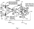
- FIG. 1 depicts various nodes and interfaces which are involved in an LCLS call.
- the "active" User Plane path 100 is for a call between two UEs 102 and 104 wherein local switching is provided between two BTS's, 106 and 108, while the "inactive" User Plane path 109, i.e. the two Abis-links, the two A-links and the links within the Core Network, are not carrying traffic and are therefore marked with dotted lines.
- the Control Plane paths 110 are also illustrated in Figure 1 .
- the radio access network part RAN 117 and the core network part CN 116 are illustrated in figure 1 .
- the radio access network RAN 117 in the embodiment in figure 1 comprises the BCS/BSS 114 and the two BTS's 106 and 108.
- the BSC/BSS 114 has the capability to perform local call switching, however other BSC/BSSs may not have such a capability.
- Various elements in the core network 116 are also shown including the originating MSC (oMSC)118, an intermediate MSC (iMSC) 120 and terminating MSC (tMSC) 122 in the signaling/control plane and various MGWs 124 in the data/control plane.
- LCLS is typically attempted to be instantiated during the call establishment phase in a radiocommunication system.
- negotiation for support of LCLS is performed within the core network (CN) and requests to correlate and connect the originating and terminating terminals (a.k.a. call legs) are made to the BSS when LCLS is successfully negotiated.
- Interaction with existing supplementary services, lawful intercept and handover are supported.
- this may require a break of an existing, locally switched call where the voice data on the user plane is routed via the core network.
- a call is locally switched through the BSS and an inter-system handover occurs to, e.g., an UMTS/LTE RAT, or an inter-BSS handover within the same RAT occurs to a BSS that does not support the LCLS feature
- an inter-system handover occurs to, e.g., an UMTS/LTE RAT, or an inter-BSS handover within the same RAT occurs to a BSS that does not support the LCLS feature
- the locally switched call is broken and normal core network switched user plane is resumed.
- UE-1 which has an ongoing call that is locally switched in the system of Figure 1
- a target BSS not shown in Figure 1
- a target RNS which does not support the LCLS feature.
- the anchor MSC sends a message to the BSS 114 (or BSC) controlling the call leg of the stationary mobile station 104 (UE-2, i.e., the mobile station that is not subject to a handover), requesting the BSS 114 to start sending user plane data UL to the core network in addition to the locally switched user plane data sent between UE-1 102 and UE-2 104.
- the user plane data from UE-2 104 is transmitted to the target BSS (or, respectively, target RNS), where it eventually will be received by UE-1 102 (when UE-1 102 has moved to the target BSS (respectively target RNS) once the handover is successfully completed).
- 3GPP Technical Specification 23.284 specifies that the BSS controlling the call leg of the stationary mobile station (UE-2, the mobile station that is not subject to a handover) at the reception of the above message from the MSC also shall be prepared to receive user plane data DL from the Core Network originating from UE-1 when the mobile station eventually has moved to the target BSS (respectively to the target RNS).
- this BSS has to autonomously, i.e. without any explicit assistance from the CN, switch the incoming user plane data path between the locally switched connection and the Core Network switched path, when user plane data from the Core Network is detected in the BSS.
- The3GPP specification referred to earlier also provides an alternative in case the in-band switch in the BSS based on the detection of the valid user plane, as described above, cannot be implemented in the BSS or will not work due to e.g. interoperability problems.
- a Clear Command message sent from the anchor MSC (triggered by a Handover Complete message received from the target BSS (or by a Relocation Complete message received from the target RNS on the Iu interface) at the successful completion of the handover procedure) to the old serving BSS of the handed over mobile station (UE-1) will break local switching and resume normal user plane switching through the Core Network from both ends.
- the BSS controlling the call leg of the stationary mobile station (UE-2, the mobile station which is not subject to a handover) will no longer use the locally switched user plane path as that path has been broken and thus receive the user plane addressed to UE-2 from the CN.
- the usage of the Clear Command message in the BSS for the purpose of triggering the switch of the user plane data path towards UE-2 104 will cause a longer break in the speech flow between the two parties compared to the same handover scenario in the legacy network (without any impact of the LCLS feature).
- the change of the target MGW user data path from one-way to both-way is triggered already at the reception of the Handover Detect message (respectively the Relocation Detect message received on the Iu interface) in the target MSC, giving the network the possibility to transmit user data from the handed over mobile station to the other end as soon as the mobile station has completed the handover.
- the time lag between the Handover Detect message and the Handover Complete message (or between the Relocation Detect message and the Relocation Complete message) has, in live networks, been measured from 200 ms up to 600 ms.
- the core network can assist in switching the user plane path for a call using LCLS which is being handed over.
- the target BSS or target RNS
- the target BSS will send the Handover Detect message (respectively Relocation Detect message) to its serving MSC.
- This Handover Detect message per se, is a legacy part of the inter-BSS handover and inter-system handover to UMTS procedures, see for example, 3GPP TS 44.018, 3GPP TS 48.008, 3GPP TS 23.205 and 3GPP TS 23.009.
- the reception of the Handover Detect message in the MSC will trigger the sending of a new control message, or an enhanced or modified version of a legacy control message, to the BSS serving the call leg of the other (stationary) mobile station (UE-2).
- the BSS Upon reception of the new control message, or the enhanced or modified version of a legacy control message, the BSS will switch the user plane data path from the locally switched connection to the Core Network switched path. As a result the user plane data is now transmitted from UE-1 102 through the Core Network to the BSS where it is further sent to UE-2 104.
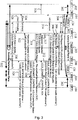
- FIG. 2 shows an exemplary signaling sequence for an embodiment wherein an inter-BSS handover breaks LCLS, and where the call leg belonging to UE-1 is handed over from the serving BSS-1 to the target BSS.
- BSS-1 is the same as BSS-2 when LCLS is established for the call, i.e., local call switching is being performed prior to the handover as indicated by arrows 200.
- a Handover Required message is sent from BSS-1 114 requesting an inter-BSS handover for UE-1 102.
- the Serving BSS-1 114 shall continue to forward the user plane data locally from UE-1 102 to UE-2 104 as long as UE-1 is served by BSS-1.
- the Anchor MSC-1 server sends the Handover Request message, as shown in step/signal 204, to the Target BSS 203 with the LCLS-Connection-Status-Control IE indicating "Connect" to through-connect the local call.
- the Target BSS 203 returns the Handover Request Acknowledge message 206 indicating that the call is not possible to be locally switched since, e.g., Target BSS 203 does not have the LCLS capability.
- the far end MSC-2 server 208 After receiving a message 210 from the anchor MSC 118 regarding LCLS disconnection, the far end MSC-2 server 208 requests the BSS-2 114 to start sending user plane data UL with the LCLS-Connect-Control message 212 and the LCLS-Connection-Status-Control Information Element (IE) indicating "BicastAtHandover". This triggers BSS-2 114 to bi-cast user plane data from UE-2 UL to the Core Network (MGW-2 124) in addition to the locally switched user plane data sent between UE-1 102 and UE-2 104. In the Core Network the user plane data is transmitted to the Target BSS 203 where it eventually will be received by UE-1 102 (when UE-1 102 has moved to the Target BSS 203). Message 212 is acknowledged via message 213.
- IE LCLS-Connection-Status-Control Information Element
- the Anchor MSC-1 118 server sends the BSSMAP Handover Command message 214 to the Serving BSS-1 114 which will trigger the BSS to send the Handover Command message 216 to UE-1 102.
- the Handover Detect message 218 is sent to the Anchor MSC-1 118.
- the Handover Detect message 218 can serve as a trigger for the user plane data path switch in the BSS.
- the Anchor MSC-1 server 118 upon reception of the Handover Detect message 218, the Anchor MSC-1 server 118 sends an LCLS status change message 220 re-using the LCLS-Status-Update message but with a new value in the LCLS-Status-Change-Request IE to the succeeding MSC server 208.
- the far end MSC-2 208 server requests BSS-2 114, via message 222, to switch Down Link (DL) user plane data path on purpose to start receiving user plane data from the Core Network 116 originating from UE-1 102.
- DL Down Link
- the message 222 does not explicitly request BSS-2 (and BSS-1) to break local switching, i.e. BSS-1/BSS-2 may continue to send user plane data locally.
- the break of local switching is initiated at reception of the Clear Command message in the old serving BSS-1, i.e., signal 226 described below.
- MSC-2 server 208 requests BSS-2 114 to break local switching and to start receiving user plane data DL from the Core Network originating from UE-1, i.e. the message 222 will stop BSS-1 and BSS-2 from sending user plane data locally between UE-1 and UE-2. Normal Core Network switched user plane is now resumed at both ends.
- the message 222 sent from the MSC-2 server 208 to BSS-2 114 could, for example, be a completely new message or a re-use of the existing LCLS-Connect-Control message with a new value in the LCLS-Connection-Status-Control IE
- the Target-BSS 203 indicates to the MSC-1 server 118 in the LCLS-BSS-Status IE that the call is not possible to be locally switched.
- the MSC-1 server 118 requests the old serving BSS-1 114 to clear the old call leg via Clear Command message 226.
- the Clear Command message will also break the local switching, i.e. sending of user plane data locally between UE-1 and UE-2 is now stopped.
- the release of local switching can already be done at the reception of the new control message 222 in BSS-2.
- the Serving BSS-2 114 informs the MSC-2 server 208 that LCLS is broken via LCLS-Notification message 228. Clearing of the old call leg in the Serving BSS-1 is completed as indicated by message 230 and the Anchor MSC-1 server 118 informs succeeding Core Network nodes that LCLS is finally disconnected via message 232. At this time, the normally switched user plane is established between UE -1 102 and UE-2 104, as indicated by arrows 234.
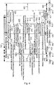
- Similar signaling/steps can be used according to embodiments and examples for performing an inter-system handover which terminates local switching, e.g., to a UMTS RAT, an example of which is provided as Figure 3 .
- a UMTS RAT an example of which is provided as Figure 3 .
- the same node numbering is used in Figure 3 to reference the similar nodes.
- the target node may be labeled as an RNS rather than a BSS in this example.
- inter-system handovers are not limited to UMTS RATs, but can be performed between any desired RATs, e.g., toward LTE RATs, etc.
- the nodes illustrated and discussed below with respect to Figure 3 as BSSs, MSCs, MGWs and RNSs can more generally be referred to as communication nodes and may be implemented differently in other RATs, e.g., LTE.
- one or more of the nodes illustrated in Figure 3 and discussed below can, instead, be an eNodeB or a node in an Evolved Packet Core (EPC), or any other communication node which performs the same or similar functions to those illustrated in Figure 3 .
- EPC Evolved Packet Core
- UE-1 102 and UE-2 104 are connected via a locally switched call using the same BSS 114 as indicated by arrows 302. Then, a Handover Required message 304 is sent from BSS-1 114 requesting an inter-System handover for UE-1 102.
- the Serving BSS-1 114 shall continue to forward the user plane data locally from UE-1 102 to UE-2 1-4 as long as UE-1 102 is served by BSS-1 114.
- the Anchor MSC-1 server 118 sends the Relocation Request message 306 to the Target RNS, and the target RNS returns the Relocation Request Acknowledge message 308.
- the far end MSC-2 server 208 Upon being informed of the change in LCLS status via message 310, the far end MSC-2 server 208 requests the BSS-2 114 to start sending user plane data UL with the LCLS-Connect-Control message 312 and the LCLS-Connection-Status-Control IE indicating "BicastAtHandover".
- Message 312 can be acknowledged by BSS-2 114 via message 313.
- Receipt of message 312 triggers BSS-2 114 to bi-cast user plane data from UE-2 UL to the Core Network 116 (e.g., MGW-2 124) in addition to the locally switched user plane data sent between UE-1 102 and UE-2 104.
- the Core Network 116 the user plane data is transmitted to the Target RNS where it eventually will be received by UE-1 102 (when UE-1 102 has moved to the Target RNS).
- the Anchor MSC-1 118 server sends the BSSMAP Handover Command message 314 to the Serving BSS-1 114, which will trigger the BSS 114 to send the Handover Command message 316 to UE-1 102.
- the Relocation Detect message 317 is sent to the Anchor MSC-1 118.
- the Relocation Detect message 317 is used as a trigger for the user plane data path switch in the BSS 114.
- the Anchor MSC-1 118 server upon the reception of the Relocation Detect message 317, the Anchor MSC-1 118 server according to an embodiment sends a LCLS status change message 318 re-using the LCLS-Status-Update message but with a new value in the LCLS-Status-Change-Request IE to the succeeding MSC server 208.
- the far end MSC-2 server 208 requests BSS-2 114, via message 320, to switch DL user plane data path on purpose to start receiving user plane data from the Core Network 116 which originates from UE-1 102.
- the message 320 does not explicitly request BSS-2 114 (and BSS-1 114) to break local switching, i.e. BSS-1/BSS-2 may continue to send user plane data locally.
- the break of local switching is initiated at reception of the Clear Command message in the old serving BSS-1 114, as described below.
- MSC-2 server 208 requests BSS-2 114 to break local switching and to start receiving user plane data DL from the Core Network 116 originating from UE-1 102, i.e. the message 320 will stop BSS-1 114 and BSS-2 114 from sending user plane data locally between UE-1 102 and UE-2 104. Normal Core Network switched user plane is now resumed at both ends.
- the message 320 sent from the MSC-2 server 208 to BSS-2 114 could be a completely new message or a re-use of the existing LCLS-Connect-Control message with a new value in the LCLS-Connection-Status-Control IE.
- the Target-RNS indicates to the MSC-1 server 118 in the LCLS-BSS-Status IE that the call is not possible to be locally switched.
- the MSC-1 server 118 requests the old serving BSS-1 114 to clear the old call leg via the Clear Command message 324.
- the Clear Command message will also break the local switching, i.e. sending of user plane data locally between UE-1 and UE-2 is now stopped.
- the release of local switching can already be done at the reception of the new control message 320 in BSS-2, as described above.'
- the Serving BSS-2 114 informs the MSC-2 server 208 that LCLS is broken via LCLS-Notification message 326. Clearing of the old call leg in the Serving BSS-1 113 is completed, as indicated by message 328.
- the Anchor MSC-1 server 118 informs succeeding Core Network nodes that LCLS is finally disconnected via message 330 and then data flows via the normally switched user plane 332 after the handover.
- the Handover Detect message as a trigger for switching the DL user plane data path in the serving BSS (or other node) for the stationary mobile station (UE-2) during an inter-system handover or an inter-node handover to a node which does not supporting the LCLS feature, the break in the speech path between the mobile station (UE-1) now located in the target cell and the stationary mobile station (UE-2) will be minimized.
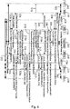
- Figures 4 and 5 illustrate other embodiments and examples of the present method where an inter-BSS ( Figure 4 ) or an inter-RAT ( Figure 5 ) handover occurs where the LCLS connection is terminated. Both figure 4 and 5 contain some minor modifications to embodiments and examples illustrated in figures 2 and 3 . In order to avoid repetition, only the additional signals in these embodiments and examples will be explained, since the remainin signaling in figures 4 and 5 is identical to the embodiments in figures 2 and 3 .
- BSS-2 transmits a LCLS_CONNECT_CONTROL Ack message 222a back to the target MSC-1 208 informing the target MSC-2 208 that the call connection between the first and second user equipments UE-1 102 and UE-2 104 is locally switched with the LCLS configuration requested by the anchor MSC-1 118 in the LCLS-Status-Change-Request message 220, Thereafter, the anchor MSC-1 118 is the informed of the completion of the switching of the user plane path between the first and second user equipments UE-1 102 and UE-2 104 by transmitting an LCLS-Status-Change-Request Ack message 220a from the target MSC-2 208 to the anchor MSC-1 118.
- This message informs the MSC-1 118 that disconnection of the locally switched call connection between UE-1 102 and UE-2 104 is prepared and that the request for change of the locally switched call connection between the two user equipments UE-1 102 and UE-2 104 has been accepted.
- the signals LCLS_CONNECT_CONTROL Ack message 320a and an LCLS-Status-Change-Request Ack message 318a are analogous to signals with reference numbers 222a and 220a mentioned in the previous paragraph and will thus not be explained again.
- the foregoing methods and signaling schemes can be embodied in nodes or structures which are configured to perform the steps described in the above embodiments and examples.
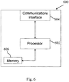
- An exemplary BSS, eNodeB, MSC or other node 600 described above is generically illustrated in Figure 6 .
- the node 600 can include a processor 602 connected to one or more communication interfaces 604.
- the processor 602 is configured to analyze and process signals received from the communications interface(s) 604 and to transmit messages or signals using the communications interface, e.g., as described above with respect to Figures 2 , 3 , 4 and 5 .
- the node 600 includes air interface capability, e.g., if node 600 is or includes base station functionality, then the node 600 includes one or more antennas (not shown) connected to processor 600 via a transceiver.
- the processor 600 may also be connected to one or more memory device 606 in which software code or program instructions can be stored for execution by the processor 600 to, for example, generate the messages described above.
Landscapes
- Engineering & Computer Science (AREA)
- Computer Networks & Wireless Communication (AREA)
- Signal Processing (AREA)
- Mobile Radio Communication Systems (AREA)
Description
- The present invention relates generally to telecommunications systems, and in particular, to methods, systems, devices and software associated with local call local switching at handover in radio communication systems.
- Radiocommunication networks were originally developed primarily to provide voice services over circuit-switched networks. The introduction of packet-switched bearers in, for example, the so-called 2.5G and 3G networks enabled network operators to provide data services as well as voice services. Eventually, network architectures will likely evolve toward all Internet Protocol (IP) networks which provide both voice and data services. However, network operators have a substantial investment in existing infrastructures and would, therefore, typically prefer to migrate gradually to all IP network architectures in order to allow them to extract sufficient value from their investment in existing infrastructures. Also to provide the capabilities needed to support next generation radio communication applications, while at the same time using legacy infrastructure, network operators could deploy hybrid networks wherein a next generation radio communication system is overlaid onto an existing circuit-switched or packet-switched network as a first step in the transition to an all IP-based network. Alternatively, a radio communication system can evolve from one generation to the next while still providing backward compatibility for legacy equipment.
- One example of such an evolved network is based upon the Universal Mobile Telephone System (UMTS) which is an existing third generation (3G) radio communication system that is evolving into High Speed Packet Access (HSPA) technology. Yet another alternative is the introduction of a new air interface technology within the UMTS framework, e.g., the so-called Long Term Evolution (LTE) technology. Target performance goals for LTE systems include, for example, support for 200 active calls per 5 MHz cell and sub 5 ms latency for small IP packets. Each new generation, or partial generation, of mobile communication systems add complexity and abilities to mobile communication systems and this can be expected to continue with either enhancements to proposed systems or completely new systems in the future.
- Local Call Local Switch (LCLS) is an ongoing work item within the 3GPP standardization groups GERAN (GSM/EDGE Radio Access Network) and CT (Core Network and Terminals) which is intended to save transmission resources of the Abis and/or A-interface. The LCLS feature provides the capability for the user plane (i.e. the voice data path) to be locally switched within the BSS (e.g. voice data in user plane is not backhauled to the CS Core Network) for calls that are generated and terminated by users that are served by the same BSS. The result is saving of transmission resources on the Abis and/or A-interface. LCLS may be supported on both TDM based A-interface (AoTDM) and IP based A-interface (AoIP). The
stage 2 work of the LCLS feature is specified in the 3GPP Technical Specification 23.284 bounded for Release-10 in March 2011. Document 3GPP TS 23.284, V1.2.0 (2011-02), 3rd Generation Partnership Project; Technical Specification Group Core Network and Terminals; Local Call Local Switch; Stage 2 (Release 10), in section 8.4.1.1.7.2 and figure 8.4.1.1.7.2.1 refers to a basic sequence for inter-BSS handover that breaks LCLS. However, there remain a number of issues regarding how to, for example, handover a user equipment (UE) that has an ongoing call which is locally switched to a target BSS or RNS which does not support the LCLS feature. -
- A-interface
- Interface between the BSC and the MSC\
- A-link
- Interface between the BSC and the MSC
- Abis
- Interface between the BTS and BSC
- 3GPP
- 3rd Generation Partnership Project
- BSC
- Base Station Centre
- BSS
- Base Station Subsystem
- BTS
- Base Station System
- CN
- Core Network
- CS
- Circuit Switched Core Network
- CT
- Core Network and Terminals
- DL
- Down Link
- GERAN
- GSM/EDGE Radio Access Network
- IE
- Information Element
- Iu
- Interface between MSC and RNC
- LCLS
- Local Call Local Switch
- LTE
- 3GPP Long Term Evolution
- Mc
- Interface between MSC and MGW
- MGW
- Media Gate-Way
- MSC
- Mobile Switching Centre
- MSS
- Mobile Switching Centre Server
- Nc
- Interface between MSCs
- oA
- A-interface originating call
- RAT
- Radio Access Technology
- RNC
- Radio Network Controller
- RNS
- Radio Network Subsystem
- tA
- A-interface terminating call
- TDM
- Time Division Multiplexing
- UE
- User Equipment
- UL
- Up Link
- UMTS
- Universal Mobile Telecommunications System
- The invention is defined by
independent claim 1, which refers to a method in a core network node, and by independent claim 10, which refers to a core network node. In the following, parts of the description and drawings referring to embodiments which are not covered by the claims are not presented as embodiments of the invention, but as examples useful for understanding the invention. - The exemplary embodiments described below will be understood, in conjunction with the drawings submitted herewith in which:
-
Figure 1 depicts various nodes associated with a locally switched local call in a radio communication system; -
Figure 2 depicts signaling associated with a handover involving a locally switched local call according to an embodiment; -
Figure 3 depicts signaling associated with a handover involving a locally switched local call according to another embodiment; -
Figure 4 depicts signaling associated with a handover involving a locally switched local call according to yet another embodiment -
Figure 5 depicts signaling associated with a handover involving a locally switched local call according to one another embodiment -
Figure 6 illustrates a node which can be used to implement embodiments. - The following detailed description of the exemplary embodiments refers to the accompanying drawings. The same reference numbers in different drawings identify the same or similar elements.
- As mentioned briefly above, handover in the context of local call local switched (LCLS) calls presents certain challenges. In order to better understand these challenges,
Figure 1 depicts various nodes and interfaces which are involved in an LCLS call. - The "active"
User Plane path 100 is for a call between two UEs 102 and 104 wherein local switching is provided between two BTS's, 106 and 108, while the "inactive"User Plane path 109, i.e. the two Abis-links, the two A-links and the links within the Core Network, are not carrying traffic and are therefore marked with dotted lines. TheControl Plane paths 110 are also illustrated inFigure 1 . Moreover, the radio accessnetwork part RAN 117 and the corenetwork part CN 116 are illustrated infigure 1 . As can be seen fromfigure 1 , the radioaccess network RAN 117 in the embodiment infigure 1 comprises the BCS/BSS 114 and the two BTS's 106 and 108. In this example, the BSC/BSS 114 has the capability to perform local call switching, however other BSC/BSSs may not have such a capability. Various elements in thecore network 116 are also shown including the originating MSC (oMSC)118, an intermediate MSC (iMSC) 120 and terminating MSC (tMSC) 122 in the signaling/control plane andvarious MGWs 124 in the data/control plane. - LCLS is typically attempted to be instantiated during the call establishment phase in a radiocommunication system. During this phase, negotiation for support of LCLS is performed within the core network (CN) and requests to correlate and connect the originating and terminating terminals (a.k.a. call legs) are made to the BSS when LCLS is successfully negotiated. Interaction with existing supplementary services, lawful intercept and handover are supported. Depending on the scenario, when such supplementary services are invoked, this may require a break of an existing, locally switched call where the voice data on the user plane is routed via the core network.
- When a call is locally switched through the BSS and an inter-system handover occurs to, e.g., an UMTS/LTE RAT, or an inter-BSS handover within the same RAT occurs to a BSS that does not support the LCLS feature, then the locally switched call is broken and normal core network switched user plane is resumed. For example, consider that a mobile station 102 (UE-1) which has an ongoing call that is locally switched in the system of
Figure 1 , is handed over to a target BSS (not shown inFigure 1 ), or a target RNS, which does not support the LCLS feature. As part of the inter-BSS handover preparation phase and the inter-system handover preparation phase, the anchor MSC sends a message to the BSS 114 (or BSC) controlling the call leg of the stationary mobile station 104 (UE-2, i.e., the mobile station that is not subject to a handover), requesting theBSS 114 to start sending user plane data UL to the core network in addition to the locally switched user plane data sent between UE-1 102 and UE-2 104. In the core network the user plane data from UE-2 104 is transmitted to the target BSS (or, respectively, target RNS), where it eventually will be received by UE-1 102 (when UE-1 102 has moved to the target BSS (respectively target RNS) once the handover is successfully completed). - 3GPP Technical Specification 23.284 specifies that the BSS controlling the call leg of the stationary mobile station (UE-2, the mobile station that is not subject to a handover) at the reception of the above message from the MSC also shall be prepared to receive user plane data DL from the Core Network originating from UE-1 when the mobile station eventually has moved to the target BSS (respectively to the target RNS).
- This solution implies that this BSS has to autonomously, i.e. without any explicit assistance from the CN, switch the incoming user plane data path between the locally switched connection and the Core Network switched path, when user plane data from the Core Network is detected in the BSS.
- This specific solution will unnecessarily increase the complexity of the BSS implementation when LCLS is implemented in a BSS communicating with the core network via a TDM based A-interface. The reason for this is that the TDM time slot pattern for TDM time slots "not in use" and TDM time slots "in use but not containing any user data" on the A-interface are not standardized, hence interoperability between different BSS/MSS vendors will most likely not be ensured.
- The3GPP specification referred to earlier also provides an alternative in case the in-band switch in the BSS based on the detection of the valid user plane, as described above, cannot be implemented in the BSS or will not work due to e.g. interoperability problems. In this case a Clear Command message sent from the anchor MSC (triggered by a Handover Complete message received from the target BSS (or by a Relocation Complete message received from the target RNS on the Iu interface) at the successful completion of the handover procedure) to the old serving BSS of the handed over mobile station (UE-1) will break local switching and resume normal user plane switching through the Core Network from both ends. This means that the BSS controlling the call leg of the stationary mobile station (UE-2, the mobile station which is not subject to a handover) will no longer use the locally switched user plane path as that path has been broken and thus receive the user plane addressed to UE-2 from the CN. However the usage of the Clear Command message in the BSS for the purpose of triggering the switch of the user plane data path towards UE-2 104 will cause a longer break in the speech flow between the two parties compared to the same handover scenario in the legacy network (without any impact of the LCLS feature). More specifically, in a legacy network the change of the target MGW user data path from one-way to both-way is triggered already at the reception of the Handover Detect message (respectively the Relocation Detect message received on the Iu interface) in the target MSC, giving the network the possibility to transmit user data from the handed over mobile station to the other end as soon as the mobile station has completed the handover. The time lag between the Handover Detect message and the Handover Complete message (or between the Relocation Detect message and the Relocation Complete message) has, in live networks, been measured from 200 ms up to 600 ms. This will result in an audible break in the speech flow from UE-1 102 to UE-2 104 if the Handover Complete/Clear Command message (or the Relocation Complete/Clear Command message) is used to trigger the switch of the user plane data path towards the stationary mobile unit during a handover involving LCLS.
- Instead, according to embodiments, the core network can assist in switching the user plane path for a call using LCLS which is being handed over. For example, when the mobile station 102 (UE-1) has tuned to the assigned channel in the target cell and the target BSS (or target RNS) has detected the new mobile station, the target BSS (or target RNS) will send the Handover Detect message (respectively Relocation Detect message) to its serving MSC. This Handover Detect message, per se, is a legacy part of the inter-BSS handover and inter-system handover to UMTS procedures, see for example, 3GPP TS 44.018, 3GPP TS 48.008, 3GPP TS 23.205 and 3GPP TS 23.009. However, the reception of the Handover Detect message in the MSC according to embodiments will trigger the sending of a new control message, or an enhanced or modified version of a legacy control message, to the BSS serving the call leg of the other (stationary) mobile station (UE-2). Upon reception of the new control message, or the enhanced or modified version of a legacy control message, the BSS will switch the user plane data path from the locally switched connection to the Core Network switched path. As a result the user plane data is now transmitted from UE-1 102 through the Core Network to the BSS where it is further sent to UE-2 104.
-
Figure 2 shows an exemplary signaling sequence for an embodiment wherein an inter-BSS handover breaks LCLS, and where the call leg belonging to UE-1 is handed over from the serving BSS-1 to the target BSS. Note that in this example, BSS-1 is the same as BSS-2 when LCLS is established for the call, i.e., local call switching is being performed prior to the handover as indicated byarrows 200. At step/signal 202, a Handover Required message is sent from BSS-1 114 requesting an inter-BSS handover for UE-1 102. The Serving BSS-1 114 shall continue to forward the user plane data locally from UE-1 102 to UE-2 104 as long as UE-1 is served by BSS-1. - The Anchor MSC-1 server sends the Handover Request message, as shown in step/
signal 204, to theTarget BSS 203 with the LCLS-Connection-Status-Control IE indicating "Connect" to through-connect the local call. TheTarget BSS 203 returns the Handover Request Acknowledgemessage 206 indicating that the call is not possible to be locally switched since, e.g.,Target BSS 203 does not have the LCLS capability. - After receiving a
message 210 from theanchor MSC 118 regarding LCLS disconnection, the far end MSC-2server 208 requests the BSS-2 114 to start sending user plane data UL with the LCLS-Connect-Control message 212 and the LCLS-Connection-Status-Control Information Element (IE) indicating "BicastAtHandover". This triggers BSS-2 114 to bi-cast user plane data from UE-2 UL to the Core Network (MGW-2 124) in addition to the locally switched user plane data sent between UE-1 102 and UE-2 104. In the Core Network the user plane data is transmitted to theTarget BSS 203 where it eventually will be received by UE-1 102 (when UE-1 102 has moved to the Target BSS 203).Message 212 is acknowledged viamessage 213. - The Anchor MSC-1 118 server sends the BSSMAP
Handover Command message 214 to the Serving BSS-1 114 which will trigger the BSS to send theHandover Command message 216 to UE-1 102. When UE-1 102 is detected in theTarget BSS 203, the Handover Detectmessage 218 is sent to the Anchor MSC-1 118. - According to embodiments, the Handover Detect
message 218 can serve as a trigger for the user plane data path switch in the BSS. For example, upon reception of the Handover Detectmessage 218, the Anchor MSC-1server 118 sends an LCLSstatus change message 220 re-using the LCLS-Status-Update message but with a new value in the LCLS-Status-Change-Request IE to the succeedingMSC server 208. The far end MSC-2 208 server requests BSS-2 114, viamessage 222, to switch Down Link (DL) user plane data path on purpose to start receiving user plane data from theCore Network 116 originating from UE-1 102. - According to one embodiment, the
message 222 does not explicitly request BSS-2 (and BSS-1) to break local switching, i.e. BSS-1/BSS-2 may continue to send user plane data locally. For this embodiment, the break of local switching is initiated at reception of the Clear Command message in the old serving BSS-1, i.e., signal 226 described below. As an alternative embodiment, MSC-2server 208 requests BSS-2 114 to break local switching and to start receiving user plane data DL from the Core Network originating from UE-1, i.e. themessage 222 will stop BSS-1 and BSS-2 from sending user plane data locally between UE-1 and UE-2. Normal Core Network switched user plane is now resumed at both ends. Themessage 222 sent from the MSC-2server 208 to BSS-2 114 could, for example, be a completely new message or a re-use of the existing LCLS-Connect-Control message with a new value in the LCLS-Connection-Status-Control IE - In the Handover
Complete message 224, the Target-BSS 203 indicates to the MSC-1server 118 in the LCLS-BSS-Status IE that the call is not possible to be locally switched. The MSC-1server 118 requests the old serving BSS-1 114 to clear the old call leg viaClear Command message 226. In the3GPP specification referred to earlier the Clear Command message will also break the local switching, i.e. sending of user plane data locally between UE-1 and UE-2 is now stopped. However, as an alternative (described above) the release of local switching can already be done at the reception of thenew control message 222 in BSS-2. - The Serving BSS-2 114 informs the MSC-2
server 208 that LCLS is broken via LCLS-Notification message 228. Clearing of the old call leg in the Serving BSS-1 is completed as indicated bymessage 230 and the Anchor MSC-1server 118 informs succeeding Core Network nodes that LCLS is finally disconnected viamessage 232. At this time, the normally switched user plane is established between UE -1 102 and UE-2 104, as indicated byarrows 234. - Similar signaling/steps can be used according to embodiments and examples for performing an inter-system handover which terminates local switching, e.g., to a UMTS RAT, an example of which is provided as
Figure 3 . Note that since similar nodes are used in this embodiment relative to that ofFigure 2 , the same node numbering is used inFigure 3 to reference the similar nodes. However, since this figure depicts an inter-system handover to a UMTS RAT, as opposed to an intra-system handover, the target node may be labeled as an RNS rather than a BSS in this example. Note further that inter-system handovers according to embodiments and examples are not limited to UMTS RATs, but can be performed between any desired RATs, e.g., toward LTE RATs, etc. Thus the nodes illustrated and discussed below with respect toFigure 3 as BSSs, MSCs, MGWs and RNSs can more generally be referred to as communication nodes and may be implemented differently in other RATs, e.g., LTE. For example, one or more of the nodes illustrated inFigure 3 and discussed below can, instead, be an eNodeB or a node in an Evolved Packet Core (EPC), or any other communication node which performs the same or similar functions to those illustrated inFigure 3 . - Again, prior to the handover, UE-1 102 and UE-2 104 are connected via a locally switched call using the
same BSS 114 as indicated byarrows 302. Then, a Handover Requiredmessage 304 is sent from BSS-1 114 requesting an inter-System handover for UE-1 102. The Serving BSS-1 114 shall continue to forward the user plane data locally from UE-1 102 to UE-2 1-4 as long as UE-1 102 is served by BSS-1 114. The Anchor MSC-1server 118 sends theRelocation Request message 306 to the Target RNS, and the target RNS returns the Relocation Request Acknowledgemessage 308. Upon being informed of the change in LCLS status viamessage 310, the far end MSC-2server 208 requests the BSS-2 114 to start sending user plane data UL with the LCLS-Connect-Control message 312 and the LCLS-Connection-Status-Control IE indicating "BicastAtHandover".Message 312 can be acknowledged by BSS-2 114 viamessage 313. - Receipt of
message 312, triggers BSS-2 114 to bi-cast user plane data from UE-2 UL to the Core Network 116 (e.g., MGW-2 124) in addition to the locally switched user plane data sent between UE-1 102 and UE-2 104. In theCore Network 116 the user plane data is transmitted to the Target RNS where it eventually will be received by UE-1 102 (when UE-1 102 has moved to the Target RNS). The Anchor MSC-1 118 server sends the BSSMAPHandover Command message 314 to the Serving BSS-1 114, which will trigger theBSS 114 to send theHandover Command message 316 to UE-1 102. When UE-1 102 is detected in the Target RNS, the Relocation Detectmessage 317 is sent to the Anchor MSC-1 118. According to this embodiment, the Relocation Detectmessage 317 is used as a trigger for the user plane data path switch in theBSS 114. - More specifically, upon the reception of the Relocation Detect
message 317, the Anchor MSC-1 118 server according to an embodiment sends a LCLSstatus change message 318 re-using the LCLS-Status-Update message but with a new value in the LCLS-Status-Change-Request IE to the succeedingMSC server 208. - The far end MSC-2
server 208 requests BSS-2 114, viamessage 320, to switch DL user plane data path on purpose to start receiving user plane data from theCore Network 116 which originates from UE-1 102. - According to an embodiment, the
message 320 does not explicitly request BSS-2 114 (and BSS-1 114) to break local switching, i.e. BSS-1/BSS-2 may continue to send user plane data locally. According to this embodiment, the break of local switching is initiated at reception of the Clear Command message in the old serving BSS-1 114, as described below. - As an alternative MSC-2
server 208 requests BSS-2 114 to break local switching and to start receiving user plane data DL from theCore Network 116 originating from UE-1 102, i.e. themessage 320 will stop BSS-1 114 and BSS-2 114 from sending user plane data locally between UE-1 102 and UE-2 104. Normal Core Network switched user plane is now resumed at both ends. Themessage 320 sent from the MSC-2server 208 to BSS-2 114 could be a completely new message or a re-use of the existing LCLS-Connect-Control message with a new value in the LCLS-Connection-Status-Control IE. - In the Relocation
Complete message 322, the Target-RNS indicates to the MSC-1server 118 in the LCLS-BSS-Status IE that the call is not possible to be locally switched. The MSC-1server 118 requests the old serving BSS-1 114 to clear the old call leg via theClear Command message 324. In the3GPP specification , the Clear Command message will also break the local switching, i.e. sending of user plane data locally between UE-1 and UE-2 is now stopped. However, as an alternative, the release of local switching can already be done at the reception of thenew control message 320 in BSS-2, as described above.' - The Serving BSS-2 114 informs the MSC-2
server 208 that LCLS is broken via LCLS-Notification message 326. Clearing of the old call leg in the Serving BSS-1 113 is completed, as indicated bymessage 328. The Anchor MSC-1server 118 informs succeeding Core Network nodes that LCLS is finally disconnected viamessage 330 and then data flows via the normally switcheduser plane 332 after the handover. - Thus, according to the foregoing embodiments and examples by, for example, using the Handover Detect message as a trigger for switching the DL user plane data path in the serving BSS (or other node) for the stationary mobile station (UE-2) during an inter-system handover or an inter-node handover to a node which does not supporting the LCLS feature, the break in the speech path between the mobile station (UE-1) now located in the target cell and the stationary mobile station (UE-2) will be minimized.
-
Figures 4 and5 illustrate other embodiments and examples of the present method where an inter-BSS (Figure 4 ) or an inter-RAT (Figure 5 ) handover occurs where the LCLS connection is terminated. Bothfigure 4 and5 contain some minor modifications to embodiments and examples illustrated infigures 2 and3 . In order to avoid repetition, only the additional signals in these embodiments and examples will be explained, since the remainin signaling infigures 4 and5 is identical to the embodiments infigures 2 and3 . - In
figure 4 , it is shown that the LCLS-Status-Update message 310 transmitted by theanchor MSC 118 is acknowledged by the far-end MSC-2server 208 by transmitting the LCLS-Status-Update-Ack message 310a after sending of user plane data UL via both the locally switched call connection and the core network path has begun and been acknowledged by the BSS-2 via theLCSL_CONNECT_CONTROL_Ack message 313. - Moreover, once the user plane path between the first user equipment UE-1 102 and the second user equipment UE-2 has been switched to the
core network path 109 BSS-2 transmits aLCLS_CONNECT_CONTROL Ack message 222a back to the target MSC-1 208 informing the target MSC-2 208 that the call connection between the first and second user equipments UE-1 102 and UE-2 104 is locally switched with the LCLS configuration requested by the anchor MSC-1 118 in the LCLS-Status-Change-Request message 220, Thereafter, the anchor MSC-1 118 is the informed of the completion of the switching of the user plane path between the first and second user equipments UE-1 102 and UE-2 104 by transmitting an LCLS-Status-Change-Request Ack message 220a from the target MSC-2 208 to the anchor MSC-1 118. This message informs the MSC-1 118 that disconnection of the locally switched call connection between UE-1 102 and UE-2 104 is prepared and that the request for change of the locally switched call connection between the two user equipments UE-1 102 and UE-2 104 has been accepted. - In
figure 5 , the signalsLCLS_CONNECT_CONTROL Ack message 320a and an LCLS-Status-Change-Request Ack message 318a are analogous to signals withreference numbers - The foregoing methods and signaling schemes can be embodied in nodes or structures which are configured to perform the steps described in the above embodiments and examples. An exemplary BSS, eNodeB, MSC or
other node 600 described above is generically illustrated inFigure 6 . Thenode 600 can include aprocessor 602 connected to one or more communication interfaces 604. Theprocessor 602 is configured to analyze and process signals received from the communications interface(s) 604 and to transmit messages or signals using the communications interface, e.g., as described above with respect toFigures 2 ,3 ,4 and5 . If thenode 600 includes air interface capability, e.g., ifnode 600 is or includes base station functionality, then thenode 600 includes one or more antennas (not shown) connected toprocessor 600 via a transceiver. Theprocessor 600 may also be connected to one ormore memory device 606 in which software code or program instructions can be stored for execution by theprocessor 600 to, for example, generate the messages described above.
Claims (10)
- Method in a core network node (118) for managing locally switched call connections in a wireless communication network, comprising the steps:- receiving a first message (218, 317) indicating that a first user equipment (102) connected via the locally switched call connection has been detected in a target base station subsystem, BSS (203);- transmitting, triggered by the first message (218, 317), a local call local switching status change request, LCLS-Status-Change-Request (220, 318) requesting a status change of the locally switched call connection to a second user equipment (104), wherein the LCLS-Status-Change Request message comprises a value in its information element, IE, the value being "Indicate DL data after handover", indicating reception of user plane downlink data originating at the first user equipment (102) at the second user equipment (104) via a core network switched path (109), such that a user plane data path (100) from the first user equipment (102) to the second user equipment (104) is switched to the core network path (109);- receiving, at the core network node (118) from the target BSS (203), a fourth message (224, 322) indicating that the first user equipment (102) has completed the handover and that the call connection between the handed over first user equipment (102) and the second user equipment (104) cannot be locally switched; ,- transmitting to a source base station subsystem (114), in response to the fourth message (224, 322), a fifth message (226, 324) instructing the clearing of the locally switched call connection between the first user equipment (102) and the second user equipment (104), after handover of the first user equipment (102) has been completed.
- Method according to claim 1, further comprising the step of receiving, at the core network node (118), a third message (220a, 318a) in response to the LCLS-Status-Change-Request (220, 318), indicating switching of the user plane data path (100) to the core network path (109) has been completed.
- Method according to one of the claims 1-2, wherein the first message comprises a handover detect, HO detect, message (218).
- Method according to one of the claims 1-2, wherein the first message comprises a relocation detect message (317).
- Method according to one of the claims 1-4, wherein the fourth message comprises a handover complete, HO Complete, message (224).
- Method according to one of the claims 1-4, wherein the fourth message comprises a Relocation Complete message (322).
- Method according to one of the claims 1-6, wherein the fifth message comprises a clear command message (226, 324).
- Method according to one of the claims 1-7, wherein the core network node (118) comprises a mobile switching center (MSC).
- Method according to one of the claims 1-8, wherein the locally switched call connection comprises a data or voice connection between two user equipments served by at least one network node wherein the call connection is switched locally within an additional network node controlling the at least one network node.
- Core Network node (600) adapted for a wireless communication network, comprising:- a communication interface (604) adapted for receiving and transmitting data and control information in the wireless communication network,- a processor (602) configured to analyze and process signals received from the communication interface (604), the signals comprising a first message (218, 317) indicating that a first user equipment (102) connected via a locally switched call connection has been detected in a target base station subsystem (203) and a fourth message (224, 322) indicating that the first user equipment (102) has completed the handover to the target base station subsystem (203), the processor (602) being further configured to generate a fifth message (226, 324) in response to the fourth message (224, 322) received from the communication interface (604), the fifth (226, 324) message instructing the clearing of the locally switched call connection between the first user equipment (102) and the second user equipment (104) after the first user equipment (102) has been successfully handed over to the target base station subsystem (203) and to transmit the fifth message (226, 324) to a source base station subsystem (114) via the communication interface (604);- a memory device (606) for storing software code adapted to generate messages transmitted by the processor (602) via the wireless communication network,characterized in that
the processor (602) is further configured to generate a local call local switching status change request, LCLS-Status-Change-Request (220, 318) in response to the received first message (218, 317) and to transmit the LCLS-Status-Change-Request (220, 318) via the communication interface (604) requesting a status change of the locally switched connection to the second user equipment (104), wherein the LCLS-Status-Change Request message comprises a value in its information element, IE, the value being "Indicate DL data after handover", indicating reception of user plane downlink data originating at the first user equipment (102) at the second user equipment (104) via a core network switched path (109), such that a user plane data path (100) from the first user equipment (102) to the second user equipment (104) is switched to the core network path (109) in order to receive user plane data originating from the first user equipment (102) via the core network path (109).
Applications Claiming Priority (2)
| Application Number | Priority Date | Filing Date | Title |
|---|---|---|---|
| US201161449205P | 2011-03-04 | 2011-03-04 | |
| PCT/SE2012/050218 WO2012121644A1 (en) | 2011-03-04 | 2012-02-27 | Local call local switching at handover |
Publications (2)
| Publication Number | Publication Date |
|---|---|
| EP2681964A1 EP2681964A1 (en) | 2014-01-08 |
| EP2681964B1 true EP2681964B1 (en) | 2017-10-25 |
Family
ID=45955075
Family Applications (1)
| Application Number | Title | Priority Date | Filing Date |
|---|---|---|---|
| EP12714412.9A Active EP2681964B1 (en) | 2011-03-04 | 2012-02-27 | Local call local switching at handover |
Country Status (8)
| Country | Link |
|---|---|
| US (2) | US8712419B2 (en) |
| EP (1) | EP2681964B1 (en) |
| JP (2) | JP2014508479A (en) |
| CN (1) | CN103404220B (en) |
| DK (1) | DK2681964T3 (en) |
| ES (1) | ES2657617T3 (en) |
| WO (1) | WO2012121644A1 (en) |
| ZA (1) | ZA201304738B (en) |
Families Citing this family (6)
| Publication number | Priority date | Publication date | Assignee | Title |
|---|---|---|---|---|
| WO2011018524A1 (en) * | 2009-08-14 | 2011-02-17 | Telefonaktiebolaget L M Ericsson (Publ) | Connection set-up between two terminals |
| DK2681964T3 (en) * | 2011-03-04 | 2018-01-08 | ERICSSON TELEFON AB L M (publ) | Local switching of local calls by handover |
| CN104125612B (en) * | 2013-04-28 | 2019-09-24 | 中兴通讯股份有限公司 | Discontinuous reception cycle synchronization method, system and device |
| WO2017003418A1 (en) * | 2015-06-29 | 2017-01-05 | Telefonaktiebolaget Lm Ericsson (Publ) | Methods and apparatuses for handling data traffic in a radio node having a split protocol stack |
| CN110710261B (en) * | 2018-01-19 | 2022-05-20 | Oppo广东移动通信有限公司 | Handover processing method, network device, UE, and computer storage medium |
| WO2021195843A1 (en) * | 2020-03-30 | 2021-10-07 | Lenovo (Beijing) Limited | Method and apparatus for data transmission |
Family Cites Families (15)
| Publication number | Priority date | Publication date | Assignee | Title |
|---|---|---|---|---|
| JPH08172659A (en) * | 1994-12-19 | 1996-07-02 | Nec Corp | Mobile communication system |
| US5734699A (en) * | 1995-05-04 | 1998-03-31 | Interwave Communications International, Ltd. | Cellular private branch exchanges |
| FI108269B (en) * | 1999-02-26 | 2001-12-14 | Nokia Corp | A method for determining a confidence limit in a telecommunications system |
| US7843878B2 (en) * | 2000-12-04 | 2010-11-30 | Ericsson Ab | Method and apparatus to control handoff between different wireless systems |
| US20060229054A1 (en) * | 2005-04-07 | 2006-10-12 | Esa Erola | Help desk connect |
| WO2006126923A1 (en) * | 2005-05-27 | 2006-11-30 | Telefonaktiebolaget Lm Ericsson (Publ) | Local switching in radio access networks |
| EP2059087A1 (en) * | 2007-11-06 | 2009-05-13 | Nokia Siemens Networks S.p.A. | Method for establishing circuit switched calls in a mobile radio network and mobile radio network |
| JP2010098444A (en) * | 2008-10-15 | 2010-04-30 | Ntt Docomo Inc | Exchange and communication control method |
| US8880073B2 (en) * | 2008-12-23 | 2014-11-04 | Telefonaktiebolaget Lm Ericsson (Publ) | Handover routing in CS-over-LTE-via-GAN solutions |
| CN102577576B (en) * | 2009-05-08 | 2017-03-01 | 瑞典爱立信有限公司 | local exchange |
| EP2273820A1 (en) * | 2009-06-30 | 2011-01-12 | Panasonic Corporation | Inter-VPLMN handover via a handover proxy node |
| CN101998666B (en) * | 2009-08-12 | 2014-09-10 | 中兴通讯股份有限公司 | Method for realizing local call and local exchange |
| WO2011018524A1 (en) | 2009-08-14 | 2011-02-17 | Telefonaktiebolaget L M Ericsson (Publ) | Connection set-up between two terminals |
| CN101754416B (en) * | 2009-12-31 | 2012-01-25 | 华为技术有限公司 | Method for establishing and removing interoffice local exchanging and mobile exchanging center |
| DK2681964T3 (en) * | 2011-03-04 | 2018-01-08 | ERICSSON TELEFON AB L M (publ) | Local switching of local calls by handover |
-
2012
- 2012-02-27 DK DK12714412.9T patent/DK2681964T3/en active
- 2012-02-27 WO PCT/SE2012/050218 patent/WO2012121644A1/en not_active Ceased
- 2012-02-27 ES ES12714412.9T patent/ES2657617T3/en active Active
- 2012-02-27 JP JP2013556580A patent/JP2014508479A/en active Pending
- 2012-02-27 EP EP12714412.9A patent/EP2681964B1/en active Active
- 2012-02-27 CN CN201280008939.1A patent/CN103404220B/en not_active Expired - Fee Related
- 2012-02-27 US US13/497,930 patent/US8712419B2/en active Active
-
2013
- 2013-06-25 ZA ZA2013/04738A patent/ZA201304738B/en unknown
-
2014
- 2014-03-26 US US14/225,534 patent/US9326193B2/en active Active
-
2017
- 2017-01-18 JP JP2017006962A patent/JP6386596B2/en active Active
Non-Patent Citations (1)
| Title |
|---|
| None * |
Also Published As
| Publication number | Publication date |
|---|---|
| US8712419B2 (en) | 2014-04-29 |
| DK2681964T3 (en) | 2018-01-08 |
| US20120225656A1 (en) | 2012-09-06 |
| WO2012121644A1 (en) | 2012-09-13 |
| US20140235250A1 (en) | 2014-08-21 |
| ZA201304738B (en) | 2014-09-25 |
| EP2681964A1 (en) | 2014-01-08 |
| CN103404220B (en) | 2019-04-12 |
| JP6386596B2 (en) | 2018-09-05 |
| US9326193B2 (en) | 2016-04-26 |
| ES2657617T3 (en) | 2018-03-06 |
| CN103404220A (en) | 2013-11-20 |
| JP2014508479A (en) | 2014-04-03 |
| JP2017108420A (en) | 2017-06-15 |
Similar Documents
| Publication | Publication Date | Title |
|---|---|---|
| US11665599B2 (en) | Light-weight RRC connection setup in multi-rat network | |
| KR101320984B1 (en) | Method and apparatus for handover | |
| EP2521395B1 (en) | Method of handling an inter RAT handover in wireless communication system | |
| US9578571B2 (en) | Paging for circuit switched fallback (CSFB) in long term evolution (LTE) connected mode | |
| US9516533B2 (en) | Method for reporting radio link failure information | |
| JP6386596B2 (en) | Local call local exchange during handover | |
| CN113940137B (en) | Handover during secondary cell group failure | |
| CN116648952A (en) | Method and apparatus for mobility robustness optimization | |
| KR20230009939A (en) | Communication management in the event of a master cell group failure | |
| JP5732467B2 (en) | Control method, terminal device, network node device, method and program for mobile side incoming procedure | |
| CN108024300B (en) | A method, device and system for reducing CSFB delay | |
| Ying et al. | Forward handover for voice call continuity |
Legal Events
| Date | Code | Title | Description |
|---|---|---|---|
| PUAI | Public reference made under article 153(3) epc to a published international application that has entered the european phase |
Free format text: ORIGINAL CODE: 0009012 |
|
| 17P | Request for examination filed |
Effective date: 20130620 |
|
| AK | Designated contracting states |
Kind code of ref document: A1 Designated state(s): AL AT BE BG CH CY CZ DE DK EE ES FI FR GB GR HR HU IE IS IT LI LT LU LV MC MK MT NL NO PL PT RO RS SE SI SK SM TR |
|
| DAX | Request for extension of the european patent (deleted) | ||
| 17Q | First examination report despatched |
Effective date: 20160830 |
|
| REG | Reference to a national code |
Ref country code: DE Ref legal event code: R079 Ref document number: 602012038899 Country of ref document: DE Free format text: PREVIOUS MAIN CLASS: H04W0076040000 Ipc: H04W0036000000 |
|
| GRAP | Despatch of communication of intention to grant a patent |
Free format text: ORIGINAL CODE: EPIDOSNIGR1 |
|
| RIC1 | Information provided on ipc code assigned before grant |
Ipc: H04W 36/10 20090101ALN20170516BHEP Ipc: H04W 36/00 20090101AFI20170516BHEP |
|
| INTG | Intention to grant announced |
Effective date: 20170612 |
|
| GRAS | Grant fee paid |
Free format text: ORIGINAL CODE: EPIDOSNIGR3 |
|
| GRAA | (expected) grant |
Free format text: ORIGINAL CODE: 0009210 |
|
| AK | Designated contracting states |
Kind code of ref document: B1 Designated state(s): AL AT BE BG CH CY CZ DE DK EE ES FI FR GB GR HR HU IE IS IT LI LT LU LV MC MK MT NL NO PL PT RO RS SE SI SK SM TR |
|
| REG | Reference to a national code |
Ref country code: GB Ref legal event code: FG4D |
|
| REG | Reference to a national code |
Ref country code: CH Ref legal event code: EP |
|
| REG | Reference to a national code |
Ref country code: AT Ref legal event code: REF Ref document number: 940984 Country of ref document: AT Kind code of ref document: T Effective date: 20171115 |
|
| REG | Reference to a national code |
Ref country code: SE Ref legal event code: TRGR |
|
| REG | Reference to a national code |
Ref country code: IE Ref legal event code: FG4D |
|
| REG | Reference to a national code |
Ref country code: DE Ref legal event code: R096 Ref document number: 602012038899 Country of ref document: DE |
|
| REG | Reference to a national code |
Ref country code: DK Ref legal event code: T3 Effective date: 20180103 |
|
| REG | Reference to a national code |
Ref country code: NL Ref legal event code: FP |
|
| REG | Reference to a national code |
Ref country code: FR Ref legal event code: PLFP Year of fee payment: 7 |
|
| REG | Reference to a national code |
Ref country code: ES Ref legal event code: FG2A Ref document number: 2657617 Country of ref document: ES Kind code of ref document: T3 Effective date: 20180306 |
|
| REG | Reference to a national code |
Ref country code: LT Ref legal event code: MG4D |
|
| REG | Reference to a national code |
Ref country code: AT Ref legal event code: MK05 Ref document number: 940984 Country of ref document: AT Kind code of ref document: T Effective date: 20171025 |
|
| PG25 | Lapsed in a contracting state [announced via postgrant information from national office to epo] |
Ref country code: FI Free format text: LAPSE BECAUSE OF FAILURE TO SUBMIT A TRANSLATION OF THE DESCRIPTION OR TO PAY THE FEE WITHIN THE PRESCRIBED TIME-LIMIT Effective date: 20171025 Ref country code: NO Free format text: LAPSE BECAUSE OF FAILURE TO SUBMIT A TRANSLATION OF THE DESCRIPTION OR TO PAY THE FEE WITHIN THE PRESCRIBED TIME-LIMIT Effective date: 20180125 Ref country code: LT Free format text: LAPSE BECAUSE OF FAILURE TO SUBMIT A TRANSLATION OF THE DESCRIPTION OR TO PAY THE FEE WITHIN THE PRESCRIBED TIME-LIMIT Effective date: 20171025 |
|
| PG25 | Lapsed in a contracting state [announced via postgrant information from national office to epo] |
Ref country code: RS Free format text: LAPSE BECAUSE OF FAILURE TO SUBMIT A TRANSLATION OF THE DESCRIPTION OR TO PAY THE FEE WITHIN THE PRESCRIBED TIME-LIMIT Effective date: 20171025 Ref country code: AT Free format text: LAPSE BECAUSE OF FAILURE TO SUBMIT A TRANSLATION OF THE DESCRIPTION OR TO PAY THE FEE WITHIN THE PRESCRIBED TIME-LIMIT Effective date: 20171025 Ref country code: BG Free format text: LAPSE BECAUSE OF FAILURE TO SUBMIT A TRANSLATION OF THE DESCRIPTION OR TO PAY THE FEE WITHIN THE PRESCRIBED TIME-LIMIT Effective date: 20180125 Ref country code: HR Free format text: LAPSE BECAUSE OF FAILURE TO SUBMIT A TRANSLATION OF THE DESCRIPTION OR TO PAY THE FEE WITHIN THE PRESCRIBED TIME-LIMIT Effective date: 20171025 Ref country code: LV Free format text: LAPSE BECAUSE OF FAILURE TO SUBMIT A TRANSLATION OF THE DESCRIPTION OR TO PAY THE FEE WITHIN THE PRESCRIBED TIME-LIMIT Effective date: 20171025 Ref country code: IS Free format text: LAPSE BECAUSE OF FAILURE TO SUBMIT A TRANSLATION OF THE DESCRIPTION OR TO PAY THE FEE WITHIN THE PRESCRIBED TIME-LIMIT Effective date: 20180225 |
|
| REG | Reference to a national code |
Ref country code: GR Ref legal event code: EP Ref document number: 20170403595 Country of ref document: GR Effective date: 20180518 |
|
| REG | Reference to a national code |
Ref country code: DE Ref legal event code: R097 Ref document number: 602012038899 Country of ref document: DE |
|
| PG25 | Lapsed in a contracting state [announced via postgrant information from national office to epo] |
Ref country code: SK Free format text: LAPSE BECAUSE OF FAILURE TO SUBMIT A TRANSLATION OF THE DESCRIPTION OR TO PAY THE FEE WITHIN THE PRESCRIBED TIME-LIMIT Effective date: 20171025 Ref country code: CY Free format text: LAPSE BECAUSE OF FAILURE TO SUBMIT A TRANSLATION OF THE DESCRIPTION OR TO PAY THE FEE WITHIN THE PRESCRIBED TIME-LIMIT Effective date: 20171025 Ref country code: EE Free format text: LAPSE BECAUSE OF FAILURE TO SUBMIT A TRANSLATION OF THE DESCRIPTION OR TO PAY THE FEE WITHIN THE PRESCRIBED TIME-LIMIT Effective date: 20171025 |
|
| PG25 | Lapsed in a contracting state [announced via postgrant information from national office to epo] |
Ref country code: PL Free format text: LAPSE BECAUSE OF FAILURE TO SUBMIT A TRANSLATION OF THE DESCRIPTION OR TO PAY THE FEE WITHIN THE PRESCRIBED TIME-LIMIT Effective date: 20171025 Ref country code: SM Free format text: LAPSE BECAUSE OF FAILURE TO SUBMIT A TRANSLATION OF THE DESCRIPTION OR TO PAY THE FEE WITHIN THE PRESCRIBED TIME-LIMIT Effective date: 20171025 Ref country code: RO Free format text: LAPSE BECAUSE OF FAILURE TO SUBMIT A TRANSLATION OF THE DESCRIPTION OR TO PAY THE FEE WITHIN THE PRESCRIBED TIME-LIMIT Effective date: 20171025 |
|
| PLBE | No opposition filed within time limit |
Free format text: ORIGINAL CODE: 0009261 |
|
| STAA | Information on the status of an ep patent application or granted ep patent |
Free format text: STATUS: NO OPPOSITION FILED WITHIN TIME LIMIT |
|
| REG | Reference to a national code |
Ref country code: CH Ref legal event code: PL |
|
| PG25 | Lapsed in a contracting state [announced via postgrant information from national office to epo] |
Ref country code: MC Free format text: LAPSE BECAUSE OF FAILURE TO SUBMIT A TRANSLATION OF THE DESCRIPTION OR TO PAY THE FEE WITHIN THE PRESCRIBED TIME-LIMIT Effective date: 20171025 |
|
| 26N | No opposition filed |
Effective date: 20180726 |
|
| PG25 | Lapsed in a contracting state [announced via postgrant information from national office to epo] |
Ref country code: LU Free format text: LAPSE BECAUSE OF NON-PAYMENT OF DUE FEES Effective date: 20180227 Ref country code: LI Free format text: LAPSE BECAUSE OF NON-PAYMENT OF DUE FEES Effective date: 20180228 Ref country code: CH Free format text: LAPSE BECAUSE OF NON-PAYMENT OF DUE FEES Effective date: 20180228 Ref country code: SI Free format text: LAPSE BECAUSE OF FAILURE TO SUBMIT A TRANSLATION OF THE DESCRIPTION OR TO PAY THE FEE WITHIN THE PRESCRIBED TIME-LIMIT Effective date: 20171025 |
|
| PG25 | Lapsed in a contracting state [announced via postgrant information from national office to epo] |
Ref country code: MT Free format text: LAPSE BECAUSE OF NON-PAYMENT OF DUE FEES Effective date: 20180227 |
|
| PG25 | Lapsed in a contracting state [announced via postgrant information from national office to epo] |
Ref country code: PT Free format text: LAPSE BECAUSE OF FAILURE TO SUBMIT A TRANSLATION OF THE DESCRIPTION OR TO PAY THE FEE WITHIN THE PRESCRIBED TIME-LIMIT Effective date: 20171025 Ref country code: HU Free format text: LAPSE BECAUSE OF FAILURE TO SUBMIT A TRANSLATION OF THE DESCRIPTION OR TO PAY THE FEE WITHIN THE PRESCRIBED TIME-LIMIT; INVALID AB INITIO Effective date: 20120227 |
|
| PG25 | Lapsed in a contracting state [announced via postgrant information from national office to epo] |
Ref country code: MK Free format text: LAPSE BECAUSE OF NON-PAYMENT OF DUE FEES Effective date: 20171025 |
|
| PG25 | Lapsed in a contracting state [announced via postgrant information from national office to epo] |
Ref country code: AL Free format text: LAPSE BECAUSE OF FAILURE TO SUBMIT A TRANSLATION OF THE DESCRIPTION OR TO PAY THE FEE WITHIN THE PRESCRIBED TIME-LIMIT Effective date: 20171025 |
|
| PGFP | Annual fee paid to national office [announced via postgrant information from national office to epo] |
Ref country code: GR Payment date: 20240227 Year of fee payment: 13 |
|
| PGFP | Annual fee paid to national office [announced via postgrant information from national office to epo] |
Ref country code: NL Payment date: 20240226 Year of fee payment: 13 Ref country code: IE Payment date: 20240227 Year of fee payment: 13 Ref country code: ES Payment date: 20240301 Year of fee payment: 13 |
|
| PGFP | Annual fee paid to national office [announced via postgrant information from national office to epo] |
Ref country code: DE Payment date: 20240228 Year of fee payment: 13 Ref country code: CZ Payment date: 20240207 Year of fee payment: 13 Ref country code: GB Payment date: 20240227 Year of fee payment: 13 |
|
| PGFP | Annual fee paid to national office [announced via postgrant information from national office to epo] |
Ref country code: TR Payment date: 20240214 Year of fee payment: 13 Ref country code: SE Payment date: 20240307 Year of fee payment: 13 Ref country code: IT Payment date: 20240222 Year of fee payment: 13 Ref country code: FR Payment date: 20240226 Year of fee payment: 13 Ref country code: DK Payment date: 20240226 Year of fee payment: 13 Ref country code: BE Payment date: 20240227 Year of fee payment: 13 |
|
| REG | Reference to a national code |
Ref country code: DE Ref legal event code: R119 Ref document number: 602012038899 Country of ref document: DE |
|
| REG | Reference to a national code |
Ref country code: DK Ref legal event code: EBP Effective date: 20250228 |
|
| REG | Reference to a national code |
Ref country code: SE Ref legal event code: EUG |
|
| REG | Reference to a national code |
Ref country code: NL Ref legal event code: MM Effective date: 20250301 |
|
| PG25 | Lapsed in a contracting state [announced via postgrant information from national office to epo] |
Ref country code: GR Free format text: LAPSE BECAUSE OF NON-PAYMENT OF DUE FEES Effective date: 20250903 |
|
| PG25 | Lapsed in a contracting state [announced via postgrant information from national office to epo] |
Ref country code: CZ Free format text: LAPSE BECAUSE OF NON-PAYMENT OF DUE FEES Effective date: 20250227 |
|
| GBPC | Gb: european patent ceased through non-payment of renewal fee |
Effective date: 20250227 |
|
| PG25 | Lapsed in a contracting state [announced via postgrant information from national office to epo] |
Ref country code: NL Free format text: LAPSE BECAUSE OF NON-PAYMENT OF DUE FEES Effective date: 20250301 |
|
| REG | Reference to a national code |
Ref country code: BE Ref legal event code: MM Effective date: 20250228 |
|
| PG25 | Lapsed in a contracting state [announced via postgrant information from national office to epo] |
Ref country code: DE Free format text: LAPSE BECAUSE OF NON-PAYMENT OF DUE FEES Effective date: 20250902 |
|
| PG25 | Lapsed in a contracting state [announced via postgrant information from national office to epo] |
Ref country code: GB Free format text: LAPSE BECAUSE OF NON-PAYMENT OF DUE FEES Effective date: 20250227 |
|
| PG25 | Lapsed in a contracting state [announced via postgrant information from national office to epo] |
Ref country code: DK Free format text: LAPSE BECAUSE OF NON-PAYMENT OF DUE FEES Effective date: 20250228 |
|
| PG25 | Lapsed in a contracting state [announced via postgrant information from national office to epo] |
Ref country code: FR Free format text: LAPSE BECAUSE OF NON-PAYMENT OF DUE FEES Effective date: 20250228 Ref country code: IT Free format text: LAPSE BECAUSE OF NON-PAYMENT OF DUE FEES Effective date: 20250227 |
|
| PG25 | Lapsed in a contracting state [announced via postgrant information from national office to epo] |
Ref country code: BE Free format text: LAPSE BECAUSE OF NON-PAYMENT OF DUE FEES Effective date: 20250228 |
|
| PG25 | Lapsed in a contracting state [announced via postgrant information from national office to epo] |
Ref country code: IE Free format text: LAPSE BECAUSE OF NON-PAYMENT OF DUE FEES Effective date: 20250227 |
|
| REG | Reference to a national code |
Ref country code: ES Ref legal event code: FD2A Effective date: 20260407 |
|
| PG25 | Lapsed in a contracting state [announced via postgrant information from national office to epo] |
Ref country code: ES Free format text: LAPSE BECAUSE OF NON-PAYMENT OF DUE FEES Effective date: 20250228 |