EP2681365B1 - Automated shifting of hydraulic drive systems - Google Patents
Automated shifting of hydraulic drive systems Download PDFInfo
- Publication number
- EP2681365B1 EP2681365B1 EP12710013.9A EP12710013A EP2681365B1 EP 2681365 B1 EP2681365 B1 EP 2681365B1 EP 12710013 A EP12710013 A EP 12710013A EP 2681365 B1 EP2681365 B1 EP 2681365B1
- Authority
- EP
- European Patent Office
- Prior art keywords
- signal
- power machine
- hydraulic
- displacement arrangement
- shift valve
- Prior art date
- Legal status (The legal status is an assumption and is not a legal conclusion. Google has not performed a legal analysis and makes no representation as to the accuracy of the status listed.)
- Active
Links
- 238000006073 displacement reaction Methods 0.000 claims description 84
- 239000012530 fluid Substances 0.000 claims description 55
- 238000000034 method Methods 0.000 claims description 34
- 238000004891 communication Methods 0.000 claims description 25
- 230000004044 response Effects 0.000 claims description 10
- 230000007935 neutral effect Effects 0.000 claims 4
- 230000000712 assembly Effects 0.000 description 19
- 238000000429 assembly Methods 0.000 description 19
- 238000010586 diagram Methods 0.000 description 9
- 230000007704 transition Effects 0.000 description 5
- 238000006243 chemical reaction Methods 0.000 description 4
- 230000006870 function Effects 0.000 description 3
- 238000010276 construction Methods 0.000 description 2
- 230000008878 coupling Effects 0.000 description 2
- 238000010168 coupling process Methods 0.000 description 2
- 238000005859 coupling reaction Methods 0.000 description 2
- 230000002706 hydrostatic effect Effects 0.000 description 2
- 229910000831 Steel Inorganic materials 0.000 description 1
- 238000004458 analytical method Methods 0.000 description 1
- 230000001174 ascending effect Effects 0.000 description 1
- 238000002485 combustion reaction Methods 0.000 description 1
- 230000001934 delay Effects 0.000 description 1
- 230000007246 mechanism Effects 0.000 description 1
- 238000012544 monitoring process Methods 0.000 description 1
- 230000009467 reduction Effects 0.000 description 1
- 239000010959 steel Substances 0.000 description 1
Images


Classifications
-
- F—MECHANICAL ENGINEERING; LIGHTING; HEATING; WEAPONS; BLASTING
- F15—FLUID-PRESSURE ACTUATORS; HYDRAULICS OR PNEUMATICS IN GENERAL
- F15B—SYSTEMS ACTING BY MEANS OF FLUIDS IN GENERAL; FLUID-PRESSURE ACTUATORS, e.g. SERVOMOTORS; DETAILS OF FLUID-PRESSURE SYSTEMS, NOT OTHERWISE PROVIDED FOR
- F15B13/00—Details of servomotor systems ; Valves for servomotor systems
-
- E—FIXED CONSTRUCTIONS
- E02—HYDRAULIC ENGINEERING; FOUNDATIONS; SOIL SHIFTING
- E02F—DREDGING; SOIL-SHIFTING
- E02F9/00—Component parts of dredgers or soil-shifting machines, not restricted to one of the kinds covered by groups E02F3/00 - E02F7/00
- E02F9/20—Drives; Control devices
- E02F9/22—Hydraulic or pneumatic drives
- E02F9/2253—Controlling the travelling speed of vehicles, e.g. adjusting travelling speed according to implement loads, control of hydrostatic transmission
-
- E—FIXED CONSTRUCTIONS
- E02—HYDRAULIC ENGINEERING; FOUNDATIONS; SOIL SHIFTING
- E02F—DREDGING; SOIL-SHIFTING
- E02F9/00—Component parts of dredgers or soil-shifting machines, not restricted to one of the kinds covered by groups E02F3/00 - E02F7/00
- E02F9/20—Drives; Control devices
- E02F9/22—Hydraulic or pneumatic drives
- E02F9/2278—Hydraulic circuits
- E02F9/2296—Systems with a variable displacement pump
-
- F—MECHANICAL ENGINEERING; LIGHTING; HEATING; WEAPONS; BLASTING
- F16—ENGINEERING ELEMENTS AND UNITS; GENERAL MEASURES FOR PRODUCING AND MAINTAINING EFFECTIVE FUNCTIONING OF MACHINES OR INSTALLATIONS; THERMAL INSULATION IN GENERAL
- F16H—GEARING
- F16H61/00—Control functions within control units of change-speed- or reversing-gearings for conveying rotary motion ; Control of exclusively fluid gearing, friction gearing, gearings with endless flexible members or other particular types of gearing
- F16H61/38—Control of exclusively fluid gearing
- F16H61/40—Control of exclusively fluid gearing hydrostatic
- F16H61/42—Control of exclusively fluid gearing hydrostatic involving adjustment of a pump or motor with adjustable output or capacity
- F16H61/421—Motor capacity control by electro-hydraulic control means, e.g. using solenoid valves
Definitions
- the current disclosure is related to power machines. More particularly, the current disclosure is related to drive systems for power machines.
- Many power machines such as excavators, wheel loaders including skid steer loaders and steerable axle loaders, tracked loaders and the like incorporate hydraulic or hydrostatic drive systems to propel the power machine over a support surface.
- One component in many of these types of machines is a drive motor, which receives power in the form of pressurized hydraulic fluid from a power source and converts the power into rotational motion to drive one or more wheels, tracks or other similar devices to cause the power machine to move over the support surface.
- motors with a relatively high displacement deliver higher torque but at a lower speed than motors with relatively lower displacement.
- power machines that employ a higher displacement motor are more advantageous than similar power machines that have a lower displacement motor.
- a higher torque motor is more advantageous than a lower torque motor.
- a high-speed motor is more advantageous in some situations. For example, when an operator wishes to move the power machine from one location to another on a generally flat surface, a lower torque motor that achieves higher travel speed is more advantageous.
- Some hydraulic motors have the capability to shift from a high displacement arrangement to a low displacement arrangement in response to an operator input. However, there may be instances when an operator selects the low displacement arrangement but then operates the power machine in a way that causes a high load condition on the power machine. In such situations, a hydraulic motor on the power machine may be overloaded and stall, causing the operator to shift from a low displacement arrangement to a high displacement arrangement. Alternatively, an operator may reduce travel inputs to reduce the travel signals provided to a hydraulic pump and avoid a stalling condition, but even an experienced operator will find it extremely difficult, if not impossible, to maximize the effort of such a power machine and avoid a stalling condition.
- EP 1 008 785 A2 relates to an automatic shift for a two speed hydrostatic motor on a compact tractor.
- a pressure sensor monitors the pressure in a working line supplying fluid from a pump to the monitor. When the pressure exceeds a pre-determined pressure for a certain time interval, a controller signals a solenoid to shift a pilot valve allowing fluid to shift a torque valve. The shifting of the torque valve allows fluid to reach cylinders which shift a swash plate controlling the motor's speed. Conversely, if there is a reduction in pressure below a further pre-determined pressure, the controller deactivates the solenoid, whereby the pilot valve and torque valve return to their previous positions.
- a switch is provided to allow the operator to select an automatic mode or to allow the motor to remain at either a high or a low speed setting.
- JP 2004340259 A relates to a drive system for travelling of construction machinery which aims at securing smooth turn operation by preventing sudden drop of turn speed.
- load pressure of variable displacement hydraulic motors as a drive source of right and left travelling bodies is beyond a setting value, motor capacity is enlarged.
- the speed mode is forcibly switched to the first-speed mode when spin turn operation is performed by the second-speed mode.
- the present invention relates to a power machine and a method of propelling a power machine and is defined by the features of the claims.
- a power machine having a drive system for propelling the power machine over a support surface having a drive system for propelling the power machine over a support surface.
- the drive system includes a hydraulic pressure source with at least one hydraulic pump that provides pressurized fluid as an output.
- the power machine also includes a drive assembly with a hydraulic motor, a drive control valve, a shift valve and a sensing device.
- the hydraulic motor is in fluid communication with the hydraulic pressure source and is switchable between a first displacement arrangement and a second displacement arrangement.
- the first displacement arrangement has a larger displacement than the second displacement arrangement.
- a drive control valve is operably coupled to the hydraulic pressure source and the hydraulic motor.
- the drive control valve is configured to provide pressurized fluid from the hydraulic pressure source to the hydraulic motor to cause the hydraulic motor to rotate.
- the shift valve is operably coupled to the hydraulic pressure source and receives pressurized fluid from the hydraulic pressure source.
- the shift valve provides a shift signal to the hydraulic motor assembly to selectively cause the displacement of the hydraulic motor to shift between the first displacement arrangement and the second displacement arrangement.
- the sensing device generates a load signal indicative of a load condition provided by the drive assembly.
- the power machine also includes an electronic controller.
- the electronic controller is operably coupled to the sensing device and the shift valve to provide a control signal to the shift valve to control the displacement of the hydraulic motor in response at least in part due to the load signal.
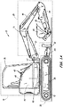
- FIGs. 1 and 1A illustrate a power machine 10 of the type upon which embodiments of the present discussion may be advantageously employed.
- the power machine 10 shown in FIGs. 1 and 1A is generally referred to as a mini-excavator, which is one example of a tracked excavator, but it should be understood that the embodiments disclosed herein may be advantageously employed on other power machines.
- Some examples of the types of power machines upon which the embodiments may be employed include wheeled loaders including rigid axle skid steer loader, suspended axle loaders, and steerable axle loaders, track loaders, wheeled excavators, utility vehicles, and the like.
- Power machine 10 includes a house 15, an undercarriage 20, a workgroup 25, and an undercarriage mounted implement such as a backfill blade 30.
- the house structure 15 includes an operator compartment 35 containing operator input devices 40 such as joysticks, switches, levers foot pedals and the like, an engine compartment or frame 45 containing an internal combustion engine and a hydraulic pressure source including one or more hydraulic pumps that are operably coupled to the engine, the combination of the engine and hydraulic pressure source shown generally as block 50 in FIG. 1A .
- the house 15 is attached to the top of the undercarriage 20 via a slew bearing 60.
- the house 15 and workgroup 25 are able to rotate or "slew" about a vertical axis on the slew bearing 60 under the influence of a slew motor (not shown) that operates under the influence of high pressure hydraulic fluid provided by the hydraulic pressure source.
- the operator input devices 40 are manipulable by an operator of the power machine 10 to selectively distribute the hydraulic fluid to the slew motor, the undercarriage 20, and/or the workgroup 25.
- the undercarriage 20 includes rubber or steel tracks 65, drive sprockets 70, rollers, and idlers.
- the drive sprockets are, in one embodiment, fixed to and driven by a drive motor (not shown in FIGs. 1 and 1A ) under the influence of high-pressure hydraulic fluid provided by the hydraulic pressure source through various hydraulic components, some of which will be described in more detail below.
- the tracks 65 rotate under the influence of the drive sprockets 70 and the power machine 10 navigates by rotating the right and left side tracks 65 forward and backward under the influence of one or more operator input devices 40.
- the workgroup 25 includes a boom 75, a dipper or arm 80, an implement 85 that is attachable to the dipper, a boom cylinder 90, a dipper cylinder 95, and an implement cylinder 96.
- the illustrated implement 85 is a bucket, but in other embodiments, the implement may include an auger, a jackhammer, or other implements suitable for the worksite.
- the workgroup 25 is attached to the front of the house 15 by way of a swing frame 92 that allows the workgroup 25 to be pivoted left or right under control of an offset cylinder (not shown) to be offset with respect to the longitudinal extent of the undercarriage 20 for worksites that require digging and trenching parallel with the tracks 65 when the house 15 is not parallel to the tracks 65.
- the hydraulic pressure source provides pressurized hydraulic fluid to the boom, dipper, and implement cylinders 90, 95, and 96 to pivot the boom 75 with respect to the house 15, the dipper 80 with respect to the boom 75, and the implement 85 with respect to the dipper 80.
- the implement 85 also receives pressurized hydraulic fluid from the hydraulic pressure source to actuate a moving part of the implement with respect to other parts of the implement 85 (e.g., moving parts of implements such as augers, saws, rotary brushes, etc.).
- At least one backfill blade cylinder 94 is pivotally interconnected between the backfill blade 30 and the undercarriage 20.
- the at least one backfill blade cylinder 94 receives pressurized hydraulic fluid from the hydraulic pressure source and extends and retracts to raise and lower the backfill blade 30 with respect to the undercarriage 20.
- the backfill blade 30 is used for grading, leveling, backfilling, trenching, and general dozing work.
- the backfill blade 30 can be lowered against the ground to lift the rest of the power machine 10 and raise the dump height of the workgroup 25.
- the backfill blade 30 can also be used to stabilize the power machine 10 during digging operations.
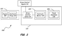
- FIG. 2 is a simple block diagram broadly illustrating the function of a drive system 100 for a vehicle such as power machine 10.
- the drive system 100 has a power source 102, which is operably coupled to a power conversion device 104.
- the power conversion device 104 receives a power signal (such as pressurized hydraulic fluid) from the power source 102 and converts it into an output, which is then transferred to at least one work element 106 that is operably coupled to the power conversion device 104.
- a power signal such as pressurized hydraulic fluid
- Power source 102 includes an engine 108 that is operably coupled to and is configured to power a hydraulic pump 110, which should be understood to represent the one or more hydraulic pumps that are part of the hydraulic pressure source referred to above.
- Hydraulic pump 110 in one embodiment, is an open loop, variable displacement pump. The hydraulic pump 110 receives fluid from a hydraulic tank (not shown in FIG. 2 ) and provides pressurized fluid to a drive assembly 115 and more particularly a drive control valve 114. Hydraulic pump 110 can be part of a hydraulic pressure source of the type discussed above and in some embodiments is one of a plurality of hydraulic pumps in a hydraulic pressure source.
- Drive control valve 114 is a spool valve or any other acceptable type of valve arrangement and is shown as a stand-alone valve in FIG.
- the drive control valve 114 can be part of a multiple valve assembly that controls other functions such as the workgroup 25 of power machine 10.
- the drive assembly 115 only those portions of such a valve assembly that are related to providing oil to other components in the drive assembly 115 are considered to be part of the drive control valve 114 and, by extension, drive assembly 115.
- the drive control valve 114 then ports pressurized fluid to the power conversion device 104, which includes at least one hydraulic motor 118, in response to signals provided by one or more operator drive control inputs 116.
- Hydraulic motor 118 is illustratively an axial piston motor (although other types of hydraulic motors such as radial piston motors or geroller motors may be employed) that converts the power received from the pressurized fluid into rotational motion, which is then provided to work element 106.
- Work element 106 can be a track drive assembly as is depicted on the power machine 10 of FIG. 1 .
- the track assembly 128 engages a support surface, such as ground and is capable of moving a vehicle.
- the work element 106 can be a wheel or a plurality of wheels that are operably connected to the hydraulic motor 118.
- hydraulic motor 118 is a two-speed hydraulic motor, meaning that it has two different displacement arrangements with a first displacement arrangement known as “low range” and a second displacement arrangement known as “high range” and that the hydraulic motor 118 can be shifted from one displacement arrangement to the other. This is accomplished in some embodiments, as discussed in more detail below, by shifting a swash plate in a hydraulic motor from one position to another. When the hydraulic motor is in low range, a larger displacement is required than when the hydraulic motor is in high range. Thus, for a given pressure and flow rate, the low range is a high torque, low speed configuration and the high range is a low torque, high-speed configuration.
- hydraulic motors may be capable of being shifted into multiple ranges, including embodiments where the displacement for a given pressure and flow is infinitely variable between a minimum displacement and a maximum displacement.
- FIG. 3 is a block diagram that illustrates a portion of drive system 100 of FIG. 2 , with additional detail provided about individual components in the drive assembly 115 of drive system 100.
- the drive system 100 is shown with first and second drive motor assemblies 150 and 152, each of which includes a hydraulic motor.
- Other drive systems with which embodiments of the present disclosure may be incorporated may have any number of drive motor assemblies.
- first drive motor assembly 150 has an output shaft (not shown in FIG. 3 ) that is operably coupled to a left track and second drive motor assembly 152 has an output shaft (not shown in FIG. 3 ) that is operably coupled to a right track.
- the first and second drive motor assemblies 150 and 152 are substantially similar. For the purposes of brevity, then, only first drive motor assembly 150 will be discussed.
- First drive motor assembly 150 is operably coupled to drive control valve 114 via first and second hydraulic conduits 154 and 156, respectively, which are each capable of providing hydraulic fluid to the hydraulic motor 118 of the first drive motor assembly 150 to cause the hydraulic motor 118 to rotate in response to signals provided via operator drive control inputs 116.
- first and second hydraulic conduits 154 and 156 are each capable of providing hydraulic fluid to the hydraulic motor 118 of the first drive motor assembly 150 to cause the hydraulic motor 118 to rotate in response to signals provided via operator drive control inputs 116.
- First drive motor assembly 150 includes a spool valve 158, which is biased to a center position by springs 160 and 162.
- spool valve 158 When hydraulic fluid is not provided from the drive control valve 114 via either of the first and second hydraulic conduits 154 and 156, spool valve 158 is biased to the center position 164 and prevents fluid from being returned to drive control valve 114 via spool valve 158 because of the presence of check valves 165 and 167.
- hydraulic fluid is provided from the drive control valve 114 to the first drive motor assembly 150 via first hydraulic conduit 154, a portion of the fluid is provided to an end 174 of spool valve 158 so that the pressure from the hydraulic fluid overcomes the spring 160 and shifts spool valve 158 into position 166.
- Fluid is then supplied to hydraulic motor 118 via hydraulic conduit 170 and returns to the drive control valve 114 via hydraulic conduit 172, spool valve 158, and second hydraulic conduit 156.
- a portion of the fluid is provided to an end 176 of spool valve 158 to overcome spring 162 and shift the spool valve 158 into position 168.
- Fluid is then supplied to hydraulic motor 118 via hydraulic conduit 172 and returns to the drive control valve 114 via hydraulic conduit 170, spool valve 158, and first hydraulic conduit 154.
- the second drive motor assembly 152 is substantially similar to the first drive motor assembly 150.
- Drive control valve 114 is operably coupled to the second drive motor assembly 152 via third and fourth hydraulic conduits 178 and 180.
- hydraulic motor 118 is an axial piston motor and displacement of the plurality of pistons (not shown) in the motor is converted into rotational motion of an output shaft.
- First drive motor assembly 150 also includes a swash plate 182, which is configured to engage the plurality of pistons in hydraulic motor 118. The angle of the swash plate 182 determines the maximum displacement of the hydraulic motor 118.
- spring 184 and piston forces bias the swash plate 182 into a first swash plate position, shown in FIG. 3 . When the swash plate 182 is in the first swash plate position, the hydraulic motor 118 is in low range, that is, a high torque, low speed configuration.
- First drive motor assembly 150 illustratively includes a pair of actuators 186 and 188 that are operably coupled to swash plate 182. Actuation of one or both of the actuators 186 and 188 illustratively causes the swash plate 182 to move from the first swash plate position, shown in FIG. 3 , to the second plate position by overcoming spring 184 and forces from the pistons (not shown) in the hydraulic motor 118. When the swash plate 182 is in the second swash plate position, the swash plate 182 engages at least one of the plurality of pistons in the hydraulic motor 118, thereby reducing the overall displacement of the hydraulic motor 118. Thus, when the swash plate 182 is in the second swash plate position, the motor is in high range, that is, relative to the low range, a low torque, high-speed configuration.
- Actuators 186 and 188 are illustratively hydraulic pistons, coupled to a valve 190.
- Valve 190 is a two-position, five-way valve.
- Valve 190 is biased into a first position 192, which puts actuators 186 and 188 in communication with tank 196, thereby allowing spring 184 to bias the actuators 186 and 188 to their default positions.
- valve 190 is in the second position 194, hydraulic conduits 170 and 172 are in hydraulic communication with actuators 186 and 188, respectively.
- hydraulic motor assembly 150 refers to an assembly that employs an axial piston motor
- other motors such as radial piston motors and geroller motors may have different arrangement, including different actuators that are capable of shifting the displacement of the motor in response to an external signal, as is discussed below.
- Valve 190 moves from one position to another based upon the presence or absence of a signal 198 provided from an external source, which is provided in the illustrated embodiment to the valve 190 from a shift valve 200.
- External signal 198 is a hydraulic signal capable of causing valve 190 to move between positions 192 and 194.
- FIG. 3 illustrates signal 198 being connected to valve 190 in drive motor assembly 150 and a valve similar to valve 190 in drive motor assembly 152.
- Shift valve 200 is a two-position, three-way valve. It is biased to a first position 202, unless signal 208 causes shift valve 200 to shift to a second position 204.
- shift valve 200 When shift valve 200 is in first position 202, signal 198 is in communication with tank 196 and valve 190 is biased into the first position 192.
- a hydraulic signal from hydraulic pump 110 is provided to signal 198, causing valve 190 to move to the second position 194.
- the signal from hydraulic pump 110 provided through second position 204 may have a reduced pressure, which may be accomplished by a pressure reducing valve (not shown).
- the signal provided through second position may be provided by a source other than hydraulic pump 110.
- a solenoid 206 is operably coupled to the shift valve 200.
- the solenoid 206 receives a signal 208 from a controller 210 to enable the shift valve 200 to move between the first position 202 and the second position 204.
- signal 208 is an electrical signal. It should be appreciated that other arrangements of two-speed drive motor assemblies and shifting valves can be employed to shift solely in response to a signal external to the drive motor assembly without departing from the scope of the present discussion.
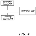
- Controller 210 in one embodiment, is an electronic controller that provides signal 208 to shift valve 200 in response to one or more inputs.
- FIG. 4 illustrates controller 210 and a plurality of inputs that can be used by the controller 210 to determine the status of signal 208.
- One input to be provided to the controller 210 is operator input 212.
- operator input 212 is an actuable switch that is wired directly to the controller 210.
- Operator input can be any acceptable device and the status of the operator input can be communicated to controller 210 via wired or wireless serial communication protocols.
- Controller 210 can measure the state of the operator input 212, or recognize transition from one state to another as an indication of whether the operator input 212 has been actuated.
- sensing device 214 is configured to sense a particular condition on the machine and provide a signal to the controller 210 indicative of the given condition.
- sensing device 214 is a pressure sensing device that is exposed to hydraulic fluid at a location in the drive system 100 so that it is capable of measuring fluid pressures in the system.
- sensing device 214 is a variable output sensor providing an indication of a sensed pressure level.
- sensing device 214 can be a switch that provides a binary output, changing states at a particular threshold.
- Sensing device 214 is illustratively provided to measure the fluid pressures in the drive assembly to determine when a high load condition exists.
- a high load condition it is meant that it is the engine that is subjected to a high load. In such a condition, the engine may not be able to support such a load and may eventually bog down or quit running, resulting in reduced performance.
- a high load condition exists when the sensing device 214 measures a pressure in the drive assembly above a given threshold level.
- This threshold value can be a constant pressure in any given condition or in the alternative may be variable, depending on different conditions such as the speed of the engine. It is known that one way to reduce the load on the engine is to shift the drive system from a high range displacement arrangement to a low range displacement arrangement, which provides additional torque to the drive system.
- a plurality of sensing devices can be incorporated into the drive system to measure pressure levels or other indicators that might be used to determine whether a high load condition exists and therefore whether controller 210 should provide a signal 208 to shift valve 200.
- the signal provided by the one or more sensing devices that are operably coupled to controller 210 can be a voltage or a current level, a wired or wireless serial communication signal or any other signal capable of being received by controller 210.
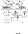
- FIG. 5 illustrates a portion of a drive system similar to that illustrated in FIG. 3 and further including operator input 212 and sensing device 214.
- the sensing device is exposed to fluid pressure in both first and second hydraulic conduits 154 and 156 via a shuttle valve 216, which is in communication with each of first and second hydraulic conduits 154 and 156 and operates to allow the higher fluid pressure in the two conduits to communicate with the pressure-sensing device 214.
- sensing device 214 is exposed to fluid pressure in third and fourth hydraulic conduits 178 and 180.
- one or more sensing devices can be used to determine whether any of the operator drive control inputs 116 are being actuated.
- the sensing devices may be the operator input devices themselves or additional sensing devices that monitor the operator input devices.
- the relationship between the operator drive control inputs 116 and controller 210 is shown by a dashed line in FIG. 5 .
- Signals indicative of the measured phenomena of each sensing device 214 is provided to controller 210.
- the controller 210 can determine whether a drive system is being subjected to a large load that is best confronted by shifting a machine that is in high range into low range.
- FIG. 5A illustrates an alternative embodiment of a portion of a drive system similar to that shown in FIG. 5 with similar components identified with the same reference numbers provided in FIG. 5 .
- a plurality of shuttle valves 218, 220, and 222 are provided to create a logic arrangement to provide the highest pressure from first, second, third and fourth hydraulic conduits 154, 156, 178, and 180 to sensing device 214.
- Shuttle valve 218 is in communication with first and second hydraulic conduits 154 and 156 and provides an output 224, which is the higher pressure of the two hydraulic conduits with which it is in communication.
- shuttle valve 220 is in communication with third and fourth hydraulic conduits 178 and 180 and provides an output 226, which is the higher pressure of third and fourth hydraulic conduits 178 and 180.
- Outputs 224 and 226 are each provided to shuttle valve 222, which operates to provide the highest pressure from the outputs 224 and 226 and thus, from first, second, third and fourth hydraulic conduits 154, 156, 178 and 180, to pressure sensing device 214.
- FIG. 5B illustrates another embodiment of a portion of a drive system similar to that shown in FIG. 3 and with the same reference numbers used to indicate similar components.
- sensing device 214 is in communication with a load sense output 228 from the drive control valve 114. Sensing device 214 thus provides a signal to controller 210 indicative of the load sense output 228 as an input to determine a load condition on the machine.
- sensing device 214 is in communication with the output 207 of the hydraulic pump 110, as shown in FIG. 5C .
- FIG. 6 illustrates a method 300 of providing a two-speed signal to one or more hydraulic motors in drive motor assemblies of the type illustrated in FIGs. 3 and 5 to shift the hydraulic motors between first and second displacement arrangements.
- the state of the operator input 212 is analyzed. If the state of operator input 212 indicates a desire on the part of an operator to operate the drive system in low range, the control signal 208 is set to a low range condition so as to allow shift valve 200 to return to a biased position, that is to move the spool to prevent pressurized hydraulic fluid to flow from the pump through shift valve 200 to the valve 190.
- controller 210 sets the control signal 208 to a low range condition.
- shift valve 200 in one embodiment, is positioned to allow valve 190 to shift to position 192 so as to allow pressurized hydraulic fluid from pistons 186 and 188 to return to tank 196 and therefore allow swash plate 182 to move to or stay in the first swash plate position.
- the control signal 208 is set to a high range condition, thereby allowing the swash plate 182 to move or stay in a second swash plate position. This is shown in block 308. As shown in FIG. 6 , once an operation is performed at block 304 or 308, the routine returns to block 302 and is performed again. It should be appreciated that there may be a small time delay between each performance of the routine, but effectively, the method 300 is performed often enough to provide virtually continuous monitoring of power machine conditions that might make an automatic shifting of the hydraulic drive motors advantageous.
- time delays may be incorporated to require high load conditions at block 306 to be present or absent for a period of time before providing a signal indicative of a shift.
- method 300 may require the presence of a high load condition for a certain period of time before providing a shifting signal to shift the motors into a low range condition.
- the method 300 may require the absence of a high load condition for a period of time before providing a shifting signal to shift the motors into a high range condition.
- different hydraulic components may function differently to the control signal 208 and such differences are within the scope of the current discussion.
- controller 210 can include memory to hold data, the pressure level at which it is determined that a high load condition exists can be stored as a set point in memory.
- multiple set points can be stored and used to make high load determinations in different situations.
- set points for other sensing devices can be stored in the memory of controller 210 to help determine whether a power machine is in a high load condition.
- an engine speed set point can be stored in the memory of controller 210 and controller 210 can monitor engine speed or communicate with other controllers (not shown in any figures) on a power machine to receive engine speed data.
- Controller 210 can also monitor a plurality of pressure sensing devices and have customizable set points for each of the pressure sensing devices, thereby providing the controller 210 with a variety of inputs to determine whether to provide a signal that is indicative of high range or low range.
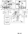
- FIG. 7 illustrates a portion of a drive system 260 similar to drive system 100 according to another illustrative embodiment. Some of the components illustrated in FIG. 7 are the same or substantially similar to those illustrated in FIG. 3 and that similarity is represented by identical reference numbers as those used in FIG. 3 . Description of those components is generally not provided here for the sake of brevity.
- drive system 260 has a shift valve 200, which receives a signal 208 from controller 210 to cause shift valve 200 to move between first position 202 and second position 204.
- Output 238 is provided as an input to an additional shifting valve 240, which is a two-position, three-way valve.
- shifting valve 240 When shifting valve 240 is in a first position 242, signal 198 is in communication with output 238 of shift valve 200.
- shifting valve 240 is in second position 244, signal 198 in communication with tank 196.
- Spring 250 illustratively urges shift valve 240 toward the first position 242.
- An input port 246 is in communication with conduit 248 to provide a pressure to input port 246.
- conduit 248 is in communication with load sense output 228 from hydraulic pump 110.
- conduit 248 can be in communication with an output 207 from hydraulic pump 110 or from a shuttle valve of the type illustrated in FIGs. 5 and 5A to measure the highest pressure from any combination of pressure lines in the drive system 260, including, for example, any combination of first, second, third, and fourth hydraulic conduits 154, 156, 178, and 180.
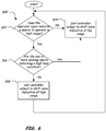
- FIG. 8 illustrates a method 400 of controlling the signal 198 provided to drive motor assemblies 150 and 152 as illustrated in FIG. 7 .
- Signal 198 provides an indication to drive motor assemblies 150 and 152 as to whether the motors 118 in each of the drive motor assemblies should be in a low range displacement arrangement or a high range displacement arrangement, each of which is described in detail above.
- an input 248 is provided to input port 246 of shifting valve 240.
- the level of input 248 is evaluated. If the input 248 is sufficient to overcome spring 250, signal 198 provided to drive motor assemblies 150 and 152 is indicative of an intention to position the drive motor assemblies 150 and 152 in a low range condition, as is shown in block 406.
- shifting valve 240 This is illustratively accomplished by placing shifting valve 240 into second position 244, thereby putting signal 198 and, by extension, valve 190 in communication with tank 196.
- shifting valve 240 When shifting valve 240 is in the second position 244, it does not matter what the output signal 208 from controller 210 is providing to shift valve 200; signal 198 is effectively controlled exclusively by shifting valve 240.
- shifting valve 240 is in the first position 242, and signal 198 is in communication with output 238.
- the method 400 determines the status of the shift valve 200. This is illustrated at block 408. If the shift valve 200 is in the first position 202, indicating that an operator input 212 has been manipulated to indicate an preference of an operator to operate the power machine 10 in low range, output 238 and signal 198 are in communication with tank 196, thereby sending an indication to position the drive motor assemblies 150 and 152 to a low range condition. This is illustrated in block 412.
- output 238 and signal 198 are in communication with hydraulic pump 110, thereby providing an indication to position the drive motor assemblies 150 and 152 to a high range condition. This is indicated by block 410.
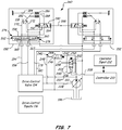
- FIG. 9 is an illustration of a portion of a drive system 300 according to yet another embodiment.
- Drive control valve 114 is operably connected to first and second drive motor assemblies 150 and 152 via first, second, third, and fourth hydraulic conduits 154, 156, 178, and 180 to provide hydraulic fluid to the first and second drive motor assemblies 150 and 152 as generally discussed above.
- a controller 210 provides an output signal 208 to a shift valve 200, which provides a signal 198 to the first and second drive motor assemblies 150 and 152.
- Drive control inputs 116 are manipulable by an operator to provide control signals to the drive control valve 114.
- a sensing device 270 senses the status of the drive control inputs 116 and provides a signal 274 to controller 210.
- the drive control inputs 116 provide hydraulic signals to the drive control valve 114 as will be discussed in more detail below.
- Sensing 270 is a variable output pressure sensor capable of measuring a pressure level.
- sensing device 270 is a switch that changes state at a given pressure level.
- An illustration of one configuration of drive control inputs and corresponding sensing device 270 is provided in FIG. 10 and is discussed in more detail below.
- a signal is sent to the controller 210 that is indicative of the status of the drive control inputs 116 without the employment of a device such as sensing device 270.
- drive control inputs 116 can be electrical devices, the signal 274 is a current, voltage, or digital signal indicative of the status of the drive control inputs provided to the controller without a sensing device 270.
- one or more sensing devices can measure movement of actuation devices such as 330, 332, 334, and 336, which are shown in FIG. 10 and discussed below.
- Such sensing devices can be proximity sensors, linear variable differential transformers (LVDTs), and the like. It should be appreciated that a number of other types of sensing devices can measure when drive control inputs have been actuated, in addition to those discussed here.
- sensing device 214 provides a signal 278 to the controller 210 indicative of the pressure in the drive system 300.
- an indicator 272 can provide a signal 276 to controller 210 indicative of the temperature of hydraulic fluid in the drive system 300.
- indicator 272 is a temperature sensor.
- one or more additional sensors or switches can provide signals to controller 210 indicative of various machine conditions, the status of which is, in some embodiments, used by the controller 210 to determine the appropriate control signal to send to the shift valve 200.
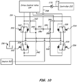
- FIG. 10 illustrates drive control inputs 116 according to one illustrative embodiment.
- Drive control inputs 116 include, in the embodiment shown in FIG. 10 a plurality of hydraulic valves 322, 324, 326, and 328 that are configured to be actuated by an operator and provide an input signal to the control valve 114.
- a hydraulic source 312 is provided to the inputs. Hydraulic source 312 can be provided from a pump such as hydraulic pump 110 or any other suitable source.
- the valves 322, 324, 326 and 328 are operably coupled to actuation devices 330, 332, 334, and 336, respectively.
- each of the valves 322, 324, 326 and 328 When in an unactuated condition, each of the valves 322, 324, 326 and 328 are open to tank 196 and provide a non-pressurized signal to the control valve 114, which is indicative of an unactuated signal.
- the actuation devices 330 and 332 are coupled together so that only one of the two actuation devices can actuate one of the hydraulic valves 322 and 324 at any given time. Thus, at most, only one of the hydraulic valves 322 and 324 can provide an actuation signal, with an actuation signal being pressurized fluid to the control valve 114.
- actuation devices 330 and 332 are opposing sides of a foot pedal that pivots in two directions about a pivot point.
- actuation devices 334 and 336 are similarly coupled such that only one of valves 326 and 328 can be actuated at any one time.
- Output lines 340 and 342 from valves 322 and 324 are provided to opposing sides of a shuttle valve 344.
- output lines 346 and 348 are provided to opposing sides of a shuttle valve 350.
- Output 352 of shuttle valve 344 and output 354 of shuttle valve 350 are provided to opposing sides of shuttle valve 356.
- the output 358 of shuttle valve 356 is thus provided to sensing devices 270, which in turn provides signal 274 to controller 210.
- sensing devices 270 is provided with a pressure indicative of that actuation.
- Sensing devices 270 then provides signal 274 to indicate whether any of the valves 322, 324, 326, and 328 are actuated.
- Controller 210 illustratively provides signal 208 to shift valve 200 based on the signals 274, 276, and 278.
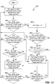
- One embodiment of a method 500 of providing a signal to the shift valve 200 is illustrated in FIG. 11 .
- signal 208 is provided to the shift valve 200 so that shift valve provides a signal 198 to each of the first and second drive motor assemblies 150 and 152 that is indicative of a high displacement, low range position.
- the settings illustrated at block 502 are considered a first state of operation for the method 500.
- the signal 274 and operator input 212 are considered.
- method 500 returns to block 502 and remains at the first state of operation.
- a timer is set.
- the status of the signal 274 and operator input 212 are considered. If the signal 274 indicates that none of the drive control inputs 116 is actuated or if operator input 212 indicates that the operator intends to operate the power machine in a high displacement, low range condition, the method 500 returns to block 502, which, as is discussed above, is the first state of operation. If, however, the signal 274 provided by sensing devices 270 to controller 210 indicates that at least one of the drive control inputs 116 is actuated and operator input 212 indicates that the operator intends to operate the power machine 10 in the low displacement, high range condition, the method moves to block 510.
- the timer is compared to a pre-determined time period and if it has been running for longer than the pre-determined time period since being reset in block 506, the method moves to block 512. If not, the method moves back to block 508 to re-examine the status of signal 274 and operator input 212. Effectively, then, the loop shown in blocks 508 and 510 form a transition state. In this transition state, a period of time must pass before it can be determined whether the operator intended to operate the power machine in high range and whether at least one of the drive control inputs was being operated during the entire time period. During this transition state, the output signal 208 remains as it was in the first state of operation. If these conditions for transition are satisfied, the method moves to the second state of operation at block 512. Otherwise, the method moves back to the first state of operation at block 502.
- the signal 208 sent to shift valve 200 is indicative of having the shift valve send a signal 198 to the first and second drive motor assemblies to shift to a low displacement, high range position.
- method 500 moves to block 514, which examines the signal 274 and the operator input 212 to determine whether the method should move back to the first state. If it is determined that the operator continues to signal an intention to operate the power machine 10 in high range and is operating at least one of the drive control inputs, the method does not return to the first state of operation.
- the signal 278 is then examined to determine whether the pressure measured by sensing device 214 is higher than a high-pressure set point. If it is determined that the pressure measured is higher than the high-pressure set point, the method moves to block 518, which is the third state of operation. If, however the pressure measured at block 516 is lower than the high-pressure set point, the method returns to block 512 and remains in the second state of operation.
- the controller 210 sends a signal 208 to shift valve 200 so that shift valve, in turn sends a signal 198 to the first and second drive motor assemblies 150 and 152 to cause the drive motor assemblies to shift to a high displacement, low range position.
- the controller 210 analyses the status of the signal 274 and the operator input 212 to determine whether the operator is still operating one or more drive control inputs and still indicates a desire to operate in the low displacement, high range condition, as is illustrated at block 520. If it is determined that the operator intends to operate the power machine in a low displacement, high range condition, the pressure indicated by signal 278 is compared to a low pressure set point.
- the method moves to the second operation state, illustrated at block 512. If the pressure indicated by pressure signal 278 is not below the low-pressure set point, the method remains at the third operating state, at block 518.
- high and low pressure set points are established to determine when to shift between the second and third operating states.
- Each of the high and low pressure set points are, in some embodiments a single value.
- the high and low-pressure set points can be set at different pressure levels based on the temperature of the hydraulic fluid in the power machine.
- indicator 272 is illustratively in communication with hydraulic fluid at an acceptable location in the drive system. Indicator 272 provides a signal 276 to the controller 210 that is indicative of the temperature of the hydraulic fluid.
- the controller 210 is configured to adjust the high and low-pressure set points based on the temperature provided.
- the set points can be established as a series of temperatures ranges. Actual temperatures may vary from one drive system to another, but are set at levels that improve shifting at various temperatures.
- the embodiments above provide several important advantages.
- power machines can be controlled in a way that improves operational efficiency with reduced input required from an operator.
- the power machine will not be in a low displacement, high range condition at any time when the power machine is not being operated, thereby reducing the likelihood of the power machine creeping.
- the embodiments disclosed herein can be implemented on any type of multiple speed hydraulic motor.
Description
- The current disclosure is related to power machines. More particularly, the current disclosure is related to drive systems for power machines. Many power machines such as excavators, wheel loaders including skid steer loaders and steerable axle loaders, tracked loaders and the like incorporate hydraulic or hydrostatic drive systems to propel the power machine over a support surface. One component in many of these types of machines is a drive motor, which receives power in the form of pressurized hydraulic fluid from a power source and converts the power into rotational motion to drive one or more wheels, tracks or other similar devices to cause the power machine to move over the support surface. For a given pressure and flow rate, motors with a relatively high displacement deliver higher torque but at a lower speed than motors with relatively lower displacement.
- In certain situations, power machines that employ a higher displacement motor are more advantageous than similar power machines that have a lower displacement motor. For example, when a power machine is engaging ground such as in a digging or grading application, ascending an incline, or negotiating a turn, a higher torque motor is more advantageous than a lower torque motor. Conversely, a high-speed motor is more advantageous in some situations. For example, when an operator wishes to move the power machine from one location to another on a generally flat surface, a lower torque motor that achieves higher travel speed is more advantageous.
- Some hydraulic motors have the capability to shift from a high displacement arrangement to a low displacement arrangement in response to an operator input. However, there may be instances when an operator selects the low displacement arrangement but then operates the power machine in a way that causes a high load condition on the power machine. In such situations, a hydraulic motor on the power machine may be overloaded and stall, causing the operator to shift from a low displacement arrangement to a high displacement arrangement. Alternatively, an operator may reduce travel inputs to reduce the travel signals provided to a hydraulic pump and avoid a stalling condition, but even an experienced operator will find it extremely difficult, if not impossible, to maximize the effort of such a power machine and avoid a stalling condition.
-
EP 1 008 785 A2 relates to an automatic shift for a two speed hydrostatic motor on a compact tractor. A pressure sensor monitors the pressure in a working line supplying fluid from a pump to the monitor. When the pressure exceeds a pre-determined pressure for a certain time interval, a controller signals a solenoid to shift a pilot valve allowing fluid to shift a torque valve. The shifting of the torque valve allows fluid to reach cylinders which shift a swash plate controlling the motor's speed. Conversely, if there is a reduction in pressure below a further pre-determined pressure, the controller deactivates the solenoid, whereby the pilot valve and torque valve return to their previous positions. In addition, a switch is provided to allow the operator to select an automatic mode or to allow the motor to remain at either a high or a low speed setting. -
JP 2004340259 A - The discussion above is merely provided for general background information and is not intended to be used as an aid in determining the scope of the claimed subject matter.
- The present invention relates to a power machine and a method of propelling a power machine and is defined by the features of the claims.
- In one illustrative embodiment, a power machine having a drive system for propelling the power machine over a support surface is disclosed. The drive system includes a hydraulic pressure source with at least one hydraulic pump that provides pressurized fluid as an output. The power machine also includes a drive assembly with a hydraulic motor, a drive control valve, a shift valve and a sensing device. The hydraulic motor is in fluid communication with the hydraulic pressure source and is switchable between a first displacement arrangement and a second displacement arrangement. The first displacement arrangement has a larger displacement than the second displacement arrangement. A drive control valve is operably coupled to the hydraulic pressure source and the hydraulic motor. The drive control valve is configured to provide pressurized fluid from the hydraulic pressure source to the hydraulic motor to cause the hydraulic motor to rotate. The shift valve is operably coupled to the hydraulic pressure source and receives pressurized fluid from the hydraulic pressure source. The shift valve provides a shift signal to the hydraulic motor assembly to selectively cause the displacement of the hydraulic motor to shift between the first displacement arrangement and the second displacement arrangement. The sensing device generates a load signal indicative of a load condition provided by the drive assembly. The power machine also includes an electronic controller. The electronic controller is operably coupled to the sensing device and the shift valve to provide a control signal to the shift valve to control the displacement of the hydraulic motor in response at least in part due to the load signal.
- This Summary is provided to introduce a selection of concepts in a simplified form that are further described below in the Detailed Description. This Summary is not intended to identify key features or essential features of the claimed subject matter, nor is it intended to be used as an aid in determining the scope of the claimed subject matter which is defined by the claims.
-
-
FIG. 1 is a perspective view of an exemplary power machine upon which embodiment of the present disclosure maybe advantageously employed. -
FIG. 1A is a side elevation view of the power machine ofFIG. 1 . -
FIG. 2 is a simplified block diagram of a drive system of a power machine such as the power machine ofFIG. 1 having a drive motor configurable between a first displacement and a second displacement. -
FIG. 3 is a block diagram illustrating a portion of the drive system ofFIG. 2 in more detail according to one illustrative embodiment. -
FIG. 4 is a block diagram that illustrates a controller that provides control signals for the drive system ofFIG. 3 and input devices that are provided to the controller according to one illustrative embodiment. -
FIGs. 5-5C are block diagrams that each illustrate a portion of a drive system of the type illustrated inFIG. 2 in more detail according to another embodiment. -
FIG. 6 is a flowchart illustrating a method for selecting between a first displacement and a second displacement in a drive motor for a power machine according to one embodiment. -
FIG. 7 is a block diagram that illustrates a portion of a drive system of the type illustrated inFIG. 2 in more detail according to another embodiment. -
FIG. 8 is a flow chart that illustrates a method of controlling the displacement arrangement of a motor according to one illustrative embodiment. -
FIG. 9 is a block diagram that illustrates a portion of a drive system of the type illustrated inFIG. 2 in more detail according to another embodiment. -
FIG. 10 is a block diagram that illustrates a portion of a drive system of the type illustrated inFIG. 2 in more detail according to another embodiment. -
FIG. 11 is a flow chart that illustrates a method of controlling the displacement arrangement of a motor according to one illustrative embodiment. - Before any embodiments are explained in detail, it is to be understood that the embodiments described herein are not limited in its application to the details of construction and the arrangement of components set forth in the following description or illustrated in the following drawings. Further, it is to be understood that the phraseology and terminology used herein is for the purpose of description and should not be regarded as limiting. The use of words such as "including," "comprising," and "having" and variations thereof herein is meant to encompass the items listed thereafter and equivalents thereof as well as additional items. Unless specified or limited otherwise, the terms "mounted," "connected," "supported," and "coupled" and variations thereof are used broadly and encompass both direct and indirect mountings, connections, supports, and couplings. Further, "connected" and "coupled" are not restricted to physical or mechanical connections or couplings.
-
FIGs. 1 and1A illustrate apower machine 10 of the type upon which embodiments of the present discussion may be advantageously employed. Thepower machine 10 shown inFIGs. 1 and1A is generally referred to as a mini-excavator, which is one example of a tracked excavator, but it should be understood that the embodiments disclosed herein may be advantageously employed on other power machines. Some examples of the types of power machines upon which the embodiments may be employed include wheeled loaders including rigid axle skid steer loader, suspended axle loaders, and steerable axle loaders, track loaders, wheeled excavators, utility vehicles, and the like. -
Power machine 10 includes a house 15, an undercarriage 20, aworkgroup 25, and an undercarriage mounted implement such as abackfill blade 30. The house structure 15 includes anoperator compartment 35 containingoperator input devices 40 such as joysticks, switches, levers foot pedals and the like, an engine compartment orframe 45 containing an internal combustion engine and a hydraulic pressure source including one or more hydraulic pumps that are operably coupled to the engine, the combination of the engine and hydraulic pressure source shown generally asblock 50 inFIG. 1A . The house 15 is attached to the top of the undercarriage 20 via a slew bearing 60. The house 15 andworkgroup 25 are able to rotate or "slew" about a vertical axis on the slew bearing 60 under the influence of a slew motor (not shown) that operates under the influence of high pressure hydraulic fluid provided by the hydraulic pressure source. Theoperator input devices 40 are manipulable by an operator of thepower machine 10 to selectively distribute the hydraulic fluid to the slew motor, the undercarriage 20, and/or theworkgroup 25. - The undercarriage 20 includes rubber or steel tracks 65, drive
sprockets 70, rollers, and idlers. The drive sprockets are, in one embodiment, fixed to and driven by a drive motor (not shown inFIGs. 1 and1A ) under the influence of high-pressure hydraulic fluid provided by the hydraulic pressure source through various hydraulic components, some of which will be described in more detail below. The tracks 65 rotate under the influence of thedrive sprockets 70 and thepower machine 10 navigates by rotating the right and left side tracks 65 forward and backward under the influence of one or moreoperator input devices 40. - The
workgroup 25 includes aboom 75, a dipper orarm 80, an implement 85 that is attachable to the dipper, aboom cylinder 90, adipper cylinder 95, and an implementcylinder 96. The illustrated implement 85 is a bucket, but in other embodiments, the implement may include an auger, a jackhammer, or other implements suitable for the worksite. Theworkgroup 25 is attached to the front of the house 15 by way of aswing frame 92 that allows theworkgroup 25 to be pivoted left or right under control of an offset cylinder (not shown) to be offset with respect to the longitudinal extent of the undercarriage 20 for worksites that require digging and trenching parallel with the tracks 65 when the house 15 is not parallel to the tracks 65. The hydraulic pressure source provides pressurized hydraulic fluid to the boom, dipper, and implementcylinders boom 75 with respect to the house 15, thedipper 80 with respect to theboom 75, and the implement 85 with respect to thedipper 80. The implement 85 also receives pressurized hydraulic fluid from the hydraulic pressure source to actuate a moving part of the implement with respect to other parts of the implement 85 (e.g., moving parts of implements such as augers, saws, rotary brushes, etc.). - At least one
backfill blade cylinder 94 is pivotally interconnected between thebackfill blade 30 and the undercarriage 20. The at least onebackfill blade cylinder 94 receives pressurized hydraulic fluid from the hydraulic pressure source and extends and retracts to raise and lower thebackfill blade 30 with respect to the undercarriage 20. Thebackfill blade 30 is used for grading, leveling, backfilling, trenching, and general dozing work. Thebackfill blade 30 can be lowered against the ground to lift the rest of thepower machine 10 and raise the dump height of theworkgroup 25. Thebackfill blade 30 can also be used to stabilize thepower machine 10 during digging operations. -
FIG. 2 is a simple block diagram broadly illustrating the function of adrive system 100 for a vehicle such aspower machine 10. Thedrive system 100 has apower source 102, which is operably coupled to apower conversion device 104. Thepower conversion device 104 receives a power signal (such as pressurized hydraulic fluid) from thepower source 102 and converts it into an output, which is then transferred to at least onework element 106 that is operably coupled to thepower conversion device 104. -
Power source 102 includes anengine 108 that is operably coupled to and is configured to power ahydraulic pump 110, which should be understood to represent the one or more hydraulic pumps that are part of the hydraulic pressure source referred to above.Hydraulic pump 110, in one embodiment, is an open loop, variable displacement pump. Thehydraulic pump 110 receives fluid from a hydraulic tank (not shown inFIG. 2 ) and provides pressurized fluid to adrive assembly 115 and more particularly adrive control valve 114.Hydraulic pump 110 can be part of a hydraulic pressure source of the type discussed above and in some embodiments is one of a plurality of hydraulic pumps in a hydraulic pressure source. Drivecontrol valve 114 is a spool valve or any other acceptable type of valve arrangement and is shown as a stand-alone valve inFIG. 2 and subsequent FIGs. in this disclosure, but it should be appreciated that thedrive control valve 114 can be part of a multiple valve assembly that controls other functions such as theworkgroup 25 ofpower machine 10. For the purposes of this discussion, only those portions of such a valve assembly that are related to providing oil to other components in thedrive assembly 115 are considered to be part of thedrive control valve 114 and, by extension,drive assembly 115. - The
drive control valve 114 then ports pressurized fluid to thepower conversion device 104, which includes at least onehydraulic motor 118, in response to signals provided by one or more operatordrive control inputs 116.Hydraulic motor 118 is illustratively an axial piston motor (although other types of hydraulic motors such as radial piston motors or geroller motors may be employed) that converts the power received from the pressurized fluid into rotational motion, which is then provided to workelement 106.Work element 106 can be a track drive assembly as is depicted on thepower machine 10 ofFIG. 1 . Thetrack assembly 128 engages a support surface, such as ground and is capable of moving a vehicle. Alternatively, thework element 106 can be a wheel or a plurality of wheels that are operably connected to thehydraulic motor 118. - In one embodiment,
hydraulic motor 118 is a two-speed hydraulic motor, meaning that it has two different displacement arrangements with a first displacement arrangement known as "low range" and a second displacement arrangement known as "high range" and that thehydraulic motor 118 can be shifted from one displacement arrangement to the other. This is accomplished in some embodiments, as discussed in more detail below, by shifting a swash plate in a hydraulic motor from one position to another. When the hydraulic motor is in low range, a larger displacement is required than when the hydraulic motor is in high range. Thus, for a given pressure and flow rate, the low range is a high torque, low speed configuration and the high range is a low torque, high-speed configuration. While the embodiments discussed herein refer to two-speed hydraulic motors, it should be appreciated that in some embodiments, hydraulic motors may be capable of being shifted into multiple ranges, including embodiments where the displacement for a given pressure and flow is infinitely variable between a minimum displacement and a maximum displacement. -
FIG. 3 is a block diagram that illustrates a portion ofdrive system 100 ofFIG. 2 , with additional detail provided about individual components in thedrive assembly 115 ofdrive system 100. Thedrive system 100 is shown with first and seconddrive motor assemblies drive motor assembly 150 has an output shaft (not shown inFIG. 3 ) that is operably coupled to a left track and seconddrive motor assembly 152 has an output shaft (not shown inFIG. 3 ) that is operably coupled to a right track. The first and seconddrive motor assemblies motor assembly 150 will be discussed. - First drive
motor assembly 150 is operably coupled to drivecontrol valve 114 via first and secondhydraulic conduits hydraulic motor 118 of the firstdrive motor assembly 150 to cause thehydraulic motor 118 to rotate in response to signals provided via operatordrive control inputs 116. In one embodiment, when hydraulic fluid is provided to firstdrive motor assembly 150 via firsthydraulic conduit 154, the output shaft of thehydraulic motor 118 rotates in a clockwise direction. Conversely, when hydraulic fluid is provided to the firstdrive motor assembly 150 via secondhydraulic conduit 156, thehydraulic motor 118 rotates in a counterclockwise direction. First drivemotor assembly 150 includes aspool valve 158, which is biased to a center position bysprings drive control valve 114 via either of the first and secondhydraulic conduits spool valve 158 is biased to thecenter position 164 and prevents fluid from being returned to drivecontrol valve 114 viaspool valve 158 because of the presence ofcheck valves drive control valve 114 to the firstdrive motor assembly 150 via firsthydraulic conduit 154, a portion of the fluid is provided to anend 174 ofspool valve 158 so that the pressure from the hydraulic fluid overcomes thespring 160 and shiftsspool valve 158 intoposition 166. Fluid is then supplied tohydraulic motor 118 viahydraulic conduit 170 and returns to thedrive control valve 114 viahydraulic conduit 172,spool valve 158, and secondhydraulic conduit 156. Conversely, when hydraulic fluid is provided from thedrive control valve 114 to the firstdrive motor assembly 150 via secondhydraulic conduit 156, a portion of the fluid is provided to anend 176 ofspool valve 158 to overcomespring 162 and shift thespool valve 158 intoposition 168. Fluid is then supplied tohydraulic motor 118 viahydraulic conduit 172 and returns to thedrive control valve 114 viahydraulic conduit 170,spool valve 158, and firsthydraulic conduit 154. As discussed above, the seconddrive motor assembly 152 is substantially similar to the firstdrive motor assembly 150. Drivecontrol valve 114 is operably coupled to the seconddrive motor assembly 152 via third and fourthhydraulic conduits - As discussed above,
hydraulic motor 118 is an axial piston motor and displacement of the plurality of pistons (not shown) in the motor is converted into rotational motion of an output shaft. First drivemotor assembly 150 also includes aswash plate 182, which is configured to engage the plurality of pistons inhydraulic motor 118. The angle of theswash plate 182 determines the maximum displacement of thehydraulic motor 118. In one embodiment,spring 184 and piston forces bias theswash plate 182 into a first swash plate position, shown inFIG. 3 . When theswash plate 182 is in the first swash plate position, thehydraulic motor 118 is in low range, that is, a high torque, low speed configuration. First drivemotor assembly 150 illustratively includes a pair ofactuators swash plate 182. Actuation of one or both of theactuators swash plate 182 to move from the first swash plate position, shown inFIG. 3 , to the second plate position by overcomingspring 184 and forces from the pistons (not shown) in thehydraulic motor 118. When theswash plate 182 is in the second swash plate position, theswash plate 182 engages at least one of the plurality of pistons in thehydraulic motor 118, thereby reducing the overall displacement of thehydraulic motor 118. Thus, when theswash plate 182 is in the second swash plate position, the motor is in high range, that is, relative to the low range, a low torque, high-speed configuration. -
Actuators valve 190.Valve 190 is a two-position, five-way valve.Valve 190 is biased into afirst position 192, which putsactuators tank 196, thereby allowingspring 184 to bias theactuators valve 190 is in thesecond position 194,hydraulic conduits actuators hydraulic conduits control valve 114 and whenvalve 190 is in itssecond position 194, hydraulic fluid is provided to at least one ofactuators hydraulic motor 118 into its high range. While the discussion ofhydraulic motor assembly 150 above refers to an assembly that employs an axial piston motor, other motors such as radial piston motors and geroller motors may have different arrangement, including different actuators that are capable of shifting the displacement of the motor in response to an external signal, as is discussed below. -
Valve 190 moves from one position to another based upon the presence or absence of asignal 198 provided from an external source, which is provided in the illustrated embodiment to thevalve 190 from ashift valve 200.External signal 198 is a hydraulic signal capable of causingvalve 190 to move betweenpositions FIG. 3 illustrates signal 198 being connected tovalve 190 indrive motor assembly 150 and a valve similar tovalve 190 indrive motor assembly 152. One of ordinary skill in the art would appreciate that other configurations ofsignal 198 andshift valve 200 can be implemented.Shift valve 200 is a two-position, three-way valve. It is biased to afirst position 202, unlesssignal 208 causes shiftvalve 200 to shift to asecond position 204. Whenshift valve 200 is infirst position 202, signal 198 is in communication withtank 196 andvalve 190 is biased into thefirst position 192. Whenshift valve 200 is in thesecond position 204, a hydraulic signal fromhydraulic pump 110 is provided to signal 198, causingvalve 190 to move to thesecond position 194. It should be appreciated that the signal fromhydraulic pump 110 provided throughsecond position 204 may have a reduced pressure, which may be accomplished by a pressure reducing valve (not shown). It should be further appreciated that, in some embodiments, the signal provided through second position may be provided by a source other thanhydraulic pump 110. In one embodiment, asolenoid 206 is operably coupled to theshift valve 200. Thesolenoid 206 receives asignal 208 from acontroller 210 to enable theshift valve 200 to move between thefirst position 202 and thesecond position 204. In one embodiment, signal 208 is an electrical signal. It should be appreciated that other arrangements of two-speed drive motor assemblies and shifting valves can be employed to shift solely in response to a signal external to the drive motor assembly without departing from the scope of the present discussion. -
Controller 210, in one embodiment, is an electronic controller that providessignal 208 to shiftvalve 200 in response to one or more inputs.FIG. 4 illustratescontroller 210 and a plurality of inputs that can be used by thecontroller 210 to determine the status ofsignal 208. One input to be provided to thecontroller 210 isoperator input 212. In one embodiment,operator input 212 is an actuable switch that is wired directly to thecontroller 210. Operator input can be any acceptable device and the status of the operator input can be communicated tocontroller 210 via wired or wireless serial communication protocols.Controller 210 can measure the state of theoperator input 212, or recognize transition from one state to another as an indication of whether theoperator input 212 has been actuated. A second input that, in one embodiment, is provided to thecontroller 210, is asensing device 214.Sensing device 214 is configured to sense a particular condition on the machine and provide a signal to thecontroller 210 indicative of the given condition. In one embodiment,sensing device 214 is a pressure sensing device that is exposed to hydraulic fluid at a location in thedrive system 100 so that it is capable of measuring fluid pressures in the system. In one embodiment,sensing device 214 is a variable output sensor providing an indication of a sensed pressure level. Alternatively sensingdevice 214 can be a switch that provides a binary output, changing states at a particular threshold.Sensing device 214 is illustratively provided to measure the fluid pressures in the drive assembly to determine when a high load condition exists. By a high load condition, it is meant that it is the engine that is subjected to a high load. In such a condition, the engine may not be able to support such a load and may eventually bog down or quit running, resulting in reduced performance. In one embodiment, it is determined that a high load condition exists when thesensing device 214 measures a pressure in the drive assembly above a given threshold level. This threshold value can be a constant pressure in any given condition or in the alternative may be variable, depending on different conditions such as the speed of the engine. It is known that one way to reduce the load on the engine is to shift the drive system from a high range displacement arrangement to a low range displacement arrangement, which provides additional torque to the drive system. Alternatively, a plurality of sensing devices can be incorporated into the drive system to measure pressure levels or other indicators that might be used to determine whether a high load condition exists and therefore whethercontroller 210 should provide asignal 208 to shiftvalve 200. The signal provided by the one or more sensing devices that are operably coupled tocontroller 210 can be a voltage or a current level, a wired or wireless serial communication signal or any other signal capable of being received bycontroller 210. -
FIG. 5 illustrates a portion of a drive system similar to that illustrated inFIG. 3 and further includingoperator input 212 andsensing device 214. In the illustrated embodiment, the sensing device is exposed to fluid pressure in both first and secondhydraulic conduits shuttle valve 216, which is in communication with each of first and secondhydraulic conduits device 214. In other embodiments,sensing device 214 is exposed to fluid pressure in third and fourthhydraulic conduits hydraulic conduits hydraulic conduits drive control inputs 116 are being actuated. The sensing devices may be the operator input devices themselves or additional sensing devices that monitor the operator input devices. The relationship between the operatordrive control inputs 116 andcontroller 210 is shown by a dashed line inFIG. 5 . Signals indicative of the measured phenomena of eachsensing device 214 is provided tocontroller 210. By measuring the pressure of the hydraulic conduits and by incorporating other collected information, thecontroller 210 can determine whether a drive system is being subjected to a large load that is best confronted by shifting a machine that is in high range into low range. -
FIG. 5A illustrates an alternative embodiment of a portion of a drive system similar to that shown inFIG. 5 with similar components identified with the same reference numbers provided inFIG. 5 . In the embodiment shown inFIG. 5A , a plurality ofshuttle valves hydraulic conduits sensing device 214.Shuttle valve 218 is in communication with first and secondhydraulic conduits output 224, which is the higher pressure of the two hydraulic conduits with which it is in communication. Similarly,shuttle valve 220 is in communication with third and fourthhydraulic conduits output 226, which is the higher pressure of third and fourthhydraulic conduits Outputs shuttle valve 222, which operates to provide the highest pressure from theoutputs hydraulic conduits sensing device 214. -
FIG. 5B illustrates another embodiment of a portion of a drive system similar to that shown inFIG. 3 and with the same reference numbers used to indicate similar components. InFIG. 5B ,sensing device 214 is in communication with aload sense output 228 from thedrive control valve 114.Sensing device 214 thus provides a signal tocontroller 210 indicative of theload sense output 228 as an input to determine a load condition on the machine. In still another embodiment,sensing device 214 is in communication with theoutput 207 of thehydraulic pump 110, as shown inFIG. 5C . -
FIG. 6 illustrates amethod 300 of providing a two-speed signal to one or more hydraulic motors in drive motor assemblies of the type illustrated inFIGs. 3 and5 to shift the hydraulic motors between first and second displacement arrangements. Inblock 302, the state of theoperator input 212 is analyzed. If the state ofoperator input 212 indicates a desire on the part of an operator to operate the drive system in low range, thecontrol signal 208 is set to a low range condition so as to allowshift valve 200 to return to a biased position, that is to move the spool to prevent pressurized hydraulic fluid to flow from the pump throughshift valve 200 to thevalve 190. As a result, theactuators swash plate 182 is urged into the first position, andhydraulic motor 118 is in the high displacement, low speed position. This is indicated inblock 304. If atblock 302 the state ofoperator input 212 indicates a desire on the part of an operator to operate the drive system in high range but the controller determines that the machine is in a high load condition, as shown atblock 306,controller 210 sets thecontrol signal 208 to a low range condition. As discussed above, when thecontrol signal 208 is set to a low range condition,shift valve 200, in one embodiment, is positioned to allowvalve 190 to shift toposition 192 so as to allow pressurized hydraulic fluid frompistons tank 196 and therefore allowswash plate 182 to move to or stay in the first swash plate position. - However, if at
block 306 it is determined that the power machine is not in a high load condition, thecontrol signal 208 is set to a high range condition, thereby allowing theswash plate 182 to move or stay in a second swash plate position. This is shown inblock 308. As shown inFIG. 6 , once an operation is performed atblock method 300 is performed often enough to provide virtually continuous monitoring of power machine conditions that might make an automatic shifting of the hydraulic drive motors advantageous. It should also be appreciated that time delays, in some embodiments, may be incorporated to require high load conditions atblock 306 to be present or absent for a period of time before providing a signal indicative of a shift. For example, if a shift valve is in a high range condition,method 300 may require the presence of a high load condition for a certain period of time before providing a shifting signal to shift the motors into a low range condition. Similarly, if the machine is in a low range condition, having been shifted into the condition because of the sensing of a high load condition, themethod 300 may require the absence of a high load condition for a period of time before providing a shifting signal to shift the motors into a high range condition. It should be understood that in different embodiments, different hydraulic components may function differently to thecontrol signal 208 and such differences are within the scope of the current discussion. - The embodiments discussed herein provide many advantages. As
controller 210 can include memory to hold data, the pressure level at which it is determined that a high load condition exists can be stored as a set point in memory. In addition, multiple set points can be stored and used to make high load determinations in different situations. In addition, set points for other sensing devices can be stored in the memory ofcontroller 210 to help determine whether a power machine is in a high load condition. For example, an engine speed set point can be stored in the memory ofcontroller 210 andcontroller 210 can monitor engine speed or communicate with other controllers (not shown in any figures) on a power machine to receive engine speed data.Controller 210 can also monitor a plurality of pressure sensing devices and have customizable set points for each of the pressure sensing devices, thereby providing thecontroller 210 with a variety of inputs to determine whether to provide a signal that is indicative of high range or low range. -
FIG. 7 illustrates a portion of adrive system 260 similar todrive system 100 according to another illustrative embodiment. Some of the components illustrated inFIG. 7 are the same or substantially similar to those illustrated inFIG. 3 and that similarity is represented by identical reference numbers as those used inFIG. 3 . Description of those components is generally not provided here for the sake of brevity. - As with the drive system of
FIG. 3 ,drive system 260 has ashift valve 200, which receives asignal 208 fromcontroller 210 to causeshift valve 200 to move betweenfirst position 202 andsecond position 204.Output 238 is provided as an input to anadditional shifting valve 240, which is a two-position, three-way valve. When shiftingvalve 240 is in a first position 242, signal 198 is in communication withoutput 238 ofshift valve 200. When shiftingvalve 240 is insecond position 244, signal 198 in communication withtank 196. Spring 250 illustratively urges shiftvalve 240 toward the first position 242. Aninput port 246 is in communication withconduit 248 to provide a pressure to inputport 246. When the pressure provided atinput port 246 is sufficient enough to overcome the force of spring 250,shift valve 240 is moved into thesecond position 244. In one embodiment,conduit 248 is in communication withload sense output 228 fromhydraulic pump 110. Alternatively,conduit 248 can be in communication with anoutput 207 fromhydraulic pump 110 or from a shuttle valve of the type illustrated inFIGs. 5 and5A to measure the highest pressure from any combination of pressure lines in thedrive system 260, including, for example, any combination of first, second, third, and fourthhydraulic conduits -
FIG. 8 illustrates amethod 400 of controlling thesignal 198 provided to drivemotor assemblies FIG. 7 .Signal 198 provides an indication to drivemotor assemblies motors 118 in each of the drive motor assemblies should be in a low range displacement arrangement or a high range displacement arrangement, each of which is described in detail above. Atblock 402, aninput 248 is provided to inputport 246 of shiftingvalve 240. Atdecision block 404, the level ofinput 248 is evaluated. If theinput 248 is sufficient to overcome spring 250, signal 198 provided to drivemotor assemblies drive motor assemblies block 406. This is illustratively accomplished by placing shiftingvalve 240 intosecond position 244, thereby puttingsignal 198 and, by extension,valve 190 in communication withtank 196. When shiftingvalve 240 is in thesecond position 244, it does not matter what theoutput signal 208 fromcontroller 210 is providing to shiftvalve 200; signal 198 is effectively controlled exclusively by shiftingvalve 240. - Returning to decision block 404, if the
input 248 is not sufficient to move shiftingvalve 240 to thesecond position 244, shiftingvalve 240 is in the first position 242, and signal 198 is in communication withoutput 238. Themethod 400 then determines the status of theshift valve 200. This is illustrated atblock 408. If theshift valve 200 is in thefirst position 202, indicating that anoperator input 212 has been manipulated to indicate an preference of an operator to operate thepower machine 10 in low range,output 238 and signal 198 are in communication withtank 196, thereby sending an indication to position thedrive motor assemblies block 412. Returning to block 408, if theshift valve 200 is in thesecond position 204, indicating that anoperator input 212 has been manipulated to indicate a preference of an operator to operate thepower machine 10 in high range,output 238 and signal 198 are in communication withhydraulic pump 110, thereby providing an indication to position thedrive motor assemblies block 410. -
FIG. 9 is an illustration of a portion of adrive system 300 according to yet another embodiment. Drivecontrol valve 114 is operably connected to first and seconddrive motor assemblies hydraulic conduits drive motor assemblies controller 210 provides anoutput signal 208 to ashift valve 200, which provides asignal 198 to the first and seconddrive motor assemblies control inputs 116 are manipulable by an operator to provide control signals to thedrive control valve 114. Asensing device 270 senses the status of thedrive control inputs 116 and provides asignal 274 tocontroller 210. In one embodiment, thedrive control inputs 116 provide hydraulic signals to thedrive control valve 114 as will be discussed in more detail below. Sensing 270, the embodiment, is a variable output pressure sensor capable of measuring a pressure level. Alternatively,sensing device 270 is a switch that changes state at a given pressure level. An illustration of one configuration of drive control inputs andcorresponding sensing device 270 is provided inFIG. 10 and is discussed in more detail below. In still other embodiments, a signal is sent to thecontroller 210 that is indicative of the status of thedrive control inputs 116 without the employment of a device such assensing device 270. For example, in some embodiments,drive control inputs 116 can be electrical devices, thesignal 274 is a current, voltage, or digital signal indicative of the status of the drive control inputs provided to the controller without asensing device 270. In other embodiments, one or more sensing devices can measure movement of actuation devices such as 330, 332, 334, and 336, which are shown inFIG. 10 and discussed below. Such sensing devices can be proximity sensors, linear variable differential transformers (LVDTs), and the like. It should be appreciated that a number of other types of sensing devices can measure when drive control inputs have been actuated, in addition to those discussed here. Additionally,sensing device 214 provides asignal 278 to thecontroller 210 indicative of the pressure in thedrive system 300. Although not shown connected to any particular part of thedrive system 300, it should be understood thatsensing device 214 could be connected to any suitable location in thedrive system 300, including locations discussed in previous embodiments. In addition, anindicator 272 can provide a signal 276 tocontroller 210 indicative of the temperature of hydraulic fluid in thedrive system 300. In one embodiment,indicator 272 is a temperature sensor. Alternatively, one or more additional sensors or switches can provide signals tocontroller 210 indicative of various machine conditions, the status of which is, in some embodiments, used by thecontroller 210 to determine the appropriate control signal to send to theshift valve 200. -
FIG. 10 illustratesdrive control inputs 116 according to one illustrative embodiment. Drivecontrol inputs 116 include, in the embodiment shown inFIG. 10 a plurality ofhydraulic valves control valve 114. Ahydraulic source 312 is provided to the inputs.Hydraulic source 312 can be provided from a pump such ashydraulic pump 110 or any other suitable source. Thevalves actuation devices valves tank 196 and provide a non-pressurized signal to thecontrol valve 114, which is indicative of an unactuated signal. In one embodiment, theactuation devices hydraulic valves hydraulic valves control valve 114. In one embodiment,actuation devices actuation devices valves -
Output lines valves shuttle valve 344. Similarly,output lines shuttle valve 350.Output 352 ofshuttle valve 344 andoutput 354 ofshuttle valve 350 are provided to opposing sides ofshuttle valve 356. Theoutput 358 ofshuttle valve 356 is thus provided tosensing devices 270, which in turn providessignal 274 tocontroller 210. Thus, whenever at least one of thevalves sensing devices 270 is provided with a pressure indicative of that actuation.Sensing devices 270 then provides signal 274 to indicate whether any of thevalves -
Controller 210 illustratively providessignal 208 to shiftvalve 200 based on thesignals method 500 of providing a signal to theshift valve 200 is illustrated inFIG. 11 . Atblock 502, signal 208 is provided to theshift valve 200 so that shift valve provides asignal 198 to each of the first and seconddrive motor assemblies block 502 are considered a first state of operation for themethod 500. Atblock 504, thesignal 274 andoperator input 212 are considered. Ifsignal 274 indicates that at least one of thedrive control inputs 116 is actuated andoperator input 212 indicates the intention of an operator to operate thepower machine 10 in a low displacement arrangement, i.e., a high range condition, andmethod 500 moves to block 506. Otherwise,method 500 returns to block 502 and remains at the first state of operation. Atblock 506, a timer is set. - At
block 508, the status of thesignal 274 andoperator input 212 are considered. If thesignal 274 indicates that none of thedrive control inputs 116 is actuated or ifoperator input 212 indicates that the operator intends to operate the power machine in a high displacement, low range condition, themethod 500 returns to block 502, which, as is discussed above, is the first state of operation. If, however, thesignal 274 provided by sensingdevices 270 tocontroller 210 indicates that at least one of thedrive control inputs 116 is actuated andoperator input 212 indicates that the operator intends to operate thepower machine 10 in the low displacement, high range condition, the method moves to block 510. Atblock 510, the timer is compared to a pre-determined time period and if it has been running for longer than the pre-determined time period since being reset inblock 506, the method moves to block 512. If not, the method moves back to block 508 to re-examine the status ofsignal 274 andoperator input 212. Effectively, then, the loop shown inblocks output signal 208 remains as it was in the first state of operation. If these conditions for transition are satisfied, the method moves to the second state of operation atblock 512. Otherwise, the method moves back to the first state of operation atblock 502. - In the second state of operation, the
signal 208 sent to shiftvalve 200 is indicative of having the shift valve send asignal 198 to the first and second drive motor assemblies to shift to a low displacement, high range position. Once the method moves to the second state of operation,method 500 moves to block 514, which examines thesignal 274 and theoperator input 212 to determine whether the method should move back to the first state. If it is determined that the operator continues to signal an intention to operate thepower machine 10 in high range and is operating at least one of the drive control inputs, the method does not return to the first state of operation. - The
signal 278 is then examined to determine whether the pressure measured by sensingdevice 214 is higher than a high-pressure set point. If it is determined that the pressure measured is higher than the high-pressure set point, the method moves to block 518, which is the third state of operation. If, however the pressure measured atblock 516 is lower than the high-pressure set point, the method returns to block 512 and remains in the second state of operation. - In the third state of operation, the
controller 210 sends asignal 208 to shiftvalve 200 so that shift valve, in turn sends asignal 198 to the first and seconddrive motor assemblies signal 208 is sent bycontroller 210, thecontroller 210 analyses the status of thesignal 274 and theoperator input 212 to determine whether the operator is still operating one or more drive control inputs and still indicates a desire to operate in the low displacement, high range condition, as is illustrated atblock 520. If it is determined that the operator intends to operate the power machine in a low displacement, high range condition, the pressure indicated bysignal 278 is compared to a low pressure set point. If thepressure signal 278 indicates a pressure below the low-pressure set point, the method moves to the second operation state, illustrated atblock 512. If the pressure indicated bypressure signal 278 is not below the low-pressure set point, the method remains at the third operating state, atblock 518. - As discussed above, in some embodiments, high and low pressure set points are established to determine when to shift between the second and third operating states. Each of the high and low pressure set points are, in some embodiments a single value. Alternatively, the high and low-pressure set points can be set at different pressure levels based on the temperature of the hydraulic fluid in the power machine. As discussed above,
indicator 272 is illustratively in communication with hydraulic fluid at an acceptable location in the drive system.Indicator 272 provides a signal 276 to thecontroller 210 that is indicative of the temperature of the hydraulic fluid. Thecontroller 210 is configured to adjust the high and low-pressure set points based on the temperature provided. The set points can be established as a series of temperatures ranges. Actual temperatures may vary from one drive system to another, but are set at levels that improve shifting at various temperatures. - The embodiments above provide several important advantages. By providing an automated shifting mechanism that interfaces with multiple speed hydraulic motors, power machines can be controlled in a way that improves operational efficiency with reduced input required from an operator. By implementing the states of operation as described above, the power machine will not be in a low displacement, high range condition at any time when the power machine is not being operated, thereby reducing the likelihood of the power machine creeping. The embodiments disclosed herein can be implemented on any type of multiple speed hydraulic motor.
Claims (17)
- A power machine (100) having a drive system for propelling the power machine over a support surface, the drive system including a hydraulic pressure source (110) including at least one hydraulic pump capable of providing pressurized fluid as an output and a drive assembly (115) including a hydraulic motor (118) in fluid communication with the hydraulic pressure source and switchable between a first displacement arrangement and a second displacement arrangement, the first displacement arrangement having a larger displacement than the second displacement arrangement and further characterized by:the drive assembly further including:a drive control valve (114) operably coupled to the hydraulic pressure source and configured to provide pressurized fluid from the hydraulic pressure source to the hydraulic motor (118) to cause the hydraulic motor to rotate;a shift valve (200, 240) configured to receive pressurized fluid from the hydraulic pressure source and provide a shift signal to the hydraulic motor for selecting one of the first displacement arrangement and the second displacement arrangement; anda sensing device (214) capable of generating a load signal indicative of a load condition provided by the drive assembly; andan electronic controller (210) in communication with the sensing device and configured to provide an electronic control signal (208) to the shift valve to control the displacement of the hydraulic motor in response at least in part to the load signal; andwherein the drive control valve is in communication with an input (246) of the shift valve (200, 400) and is configured to provide a pressure to the shift valve.
- The power machine of claim 1 and further comprising:
a first operator input (212) configured to provide an arrangement signal indicative of an intention of an operator to operate the drive system in one of the first displacement arrangement and the second displacement arrangement. - The power machine of claim 2, wherein the electronic controller is configured to provide the control signal to the shift valve for operating the hydraulic motor in the second displacement arrangement when the arrangement signal indicates an intention to operate the drive system in the second displacement arrangement and when the load signal indicates a load below a load threshold.
- The power machine of claim 2, wherein the electronic controller is configured to provide the control signal to the shift valve for operating the hydraulic motor in the first displacement arrangement when the load signal indicates a load above the load threshold.
- The power machine of claim 2, and further comprising:at least one drive control input device (212) moveable from a neutral position to an actuated position, each of the at least one drive control input devices being configured to provide an intention of an operator to move the power machine when in an actuated position; andwherein the electronic controller is configured to provide the control signal to the shift valve indicative of operating the hydraulic motor in the first displacement arrangement whenever each of the at least one drive control input devices is in a neutral position.
- The power machine of claim 5, and further comprising:
a drive control input sensing device (270) configured to sense a position of the at least one drive control input device and provide a drive control input signal to the electronic controller. - The power machine of claim 6, wherein the electronic controller is configured to provide the control signal to the shift valve for operating the hydraulic motor in the second displacement arrangement when the arrangement signal is indicative of an intention to operate the drive system in the second displacement arrangement, when the load signal indicates a load below a load threshold, and when the drive control input signal indicates that at least one of the drive control input devices is in an actuated position.
- The power machine of claim 5, wherein the drive control input device (212) is moveable to indicate an intention to move the power machine in a forward direction and wherein moving the drive control input device to indicate an intention to move the power machine in a forward direction causes the drive control input device to provide a signal indicative of an actuated position.
- The power machine of claim 5, wherein the drive control input device (212) is moveable to indicate an intention to move the power machine in a reverse direction and wherein moving the drive control input device to indicate an intention to move the power machine in a reverse direction causes the drive control input device to provide a signal indicative of an actuated position.
- The power machine of claim 1, wherein the sensing device is a pressure sensor configured to measure hydraulic pressure at an outlet of the hydraulic pump.
- The power machine of claim 1, wherein the sensing device is a pressure sensor configured to measure a highest pressure selected from a plurality of sources in the drive assembly.
- The power machine of claim 1, wherein the sensing device is a first sensing device and further comprising a second sensing device (272) capable of providing an indication of a machine condition and wherein the electronic controller is configured to provide the control signal to the shift valve in response to the indication provided by the second sensing device.
- A method of propelling a power machine (100) having a drive assembly (115) with a hydraulic motor (118) capable of driving a tractive element, the hydraulic motor capable of being shifted between a first displacement arrangement and a second displacement arrangement having a smaller displacement than the first displacement arrangement, the method comprising:selectively providing pressurized fluid from a hydraulic pressure source (110) to the hydraulic motor though a drive control valve (114) to cause the hydraulic motor to rotate while operating in a selected one of the first displacement arrangement and the second displacement arrangement;providing a shift valve (200, 240) to cause the hydraulic motor to select one of the first displacement arrangement and the second displacement arrangement; andcontrolling the shift valve by providing a shift valve signal (208) from an electronic controller to the shift valve in response to a load signal from a load sensing device (214) that provides an indication of a load provided by the drive assembly to the electronic controller and a pressure signal from the drive control valve.
- The method of claim 13, wherein controlling the shift valve further comprises providing a shift valve signal (198) and wherein the shift valve causes the hydraulic motor to select the first displacement arrangement whenever the load signal indicates a load above a given threshold.
- The method of claim 14, wherein controlling the shift valve further comprises receiving a displacement selection signal from an operator input device (212) indicative of an intention to select one of the first displacement arrangement and the second displacement arrangement and wherein the shift valve causes the hydraulic motor to select the first displacement arrangement when the operator input device is indicative of an intention to select the second displacement arrangement and the load signal indicates a load below a given threshold.
- The method of claim 14, wherein controlling the shift valve further comprises receiving an indication of one of a neutral position and an actuated position from each input device (116) dedicated to controlling propulsion of the power machine, and wherein the shift valve signal causes the hydraulic motor to select the first displacement arrangement whenever each input device provides an indication of being in the neutral position.
- The method of claim 13, wherein a load signal is provided by a sensing device (214) capable of receiving a pressure signal from a highest pressure level selected from a plurality of pressure nodes (222, 218) within the drive assembly.
Applications Claiming Priority (2)
| Application Number | Priority Date | Filing Date | Title |
|---|---|---|---|
| US201161448940P | 2011-03-03 | 2011-03-03 | |
| PCT/US2012/027513 WO2012119089A1 (en) | 2011-03-03 | 2012-03-02 | Automated shifting of hydraulic drive systems |
Publications (2)
| Publication Number | Publication Date |
|---|---|
| EP2681365A1 EP2681365A1 (en) | 2014-01-08 |
| EP2681365B1 true EP2681365B1 (en) | 2018-05-09 |
Family
ID=45873237
Family Applications (1)
| Application Number | Title | Priority Date | Filing Date |
|---|---|---|---|
| EP12710013.9A Active EP2681365B1 (en) | 2011-03-03 | 2012-03-02 | Automated shifting of hydraulic drive systems |
Country Status (6)
| Country | Link |
|---|---|
| US (1) | US9382925B2 (en) |
| EP (1) | EP2681365B1 (en) |
| CN (1) | CN102971467B (en) |
| CA (1) | CA2804017C (en) |
| ES (1) | ES2682246T3 (en) |
| WO (1) | WO2012119089A1 (en) |
Families Citing this family (9)
| Publication number | Priority date | Publication date | Assignee | Title |
|---|---|---|---|---|
| US20140260224A1 (en) * | 2013-03-14 | 2014-09-18 | Clark Equipment Company | Control System for Variable Displacement Hydraulic Motor |
| NL1040157C2 (en) * | 2013-04-12 | 2014-10-14 | Hudson Bay Holding B V | MOBILE DEVICE WITH CONTROL SYSTEM. |
| GB2531762A (en) | 2014-10-29 | 2016-05-04 | Bamford Excavators Ltd | Working machine |
| DE102014117355A1 (en) * | 2014-11-26 | 2016-06-02 | Linde Hydraulics Gmbh & Co. Kg | Hydrostatic drive |
| JP2017075505A (en) * | 2015-10-16 | 2017-04-20 | 株式会社アイメック | Loader work machine |
| JP6685783B2 (en) * | 2016-03-16 | 2020-04-22 | 住友建機株式会社 | Excavator |
| JP6959905B2 (en) * | 2018-11-29 | 2021-11-05 | 日立建機株式会社 | Hydraulic drive |
| WO2021021943A1 (en) | 2019-07-29 | 2021-02-04 | Great Plains Manufacturing, Inc. | Compact utility loader |
| CN114402150A (en) * | 2019-09-19 | 2022-04-26 | 克拉克设备公司 | Displacement control device for drive motor |
Family Cites Families (25)
| Publication number | Priority date | Publication date | Assignee | Title |
|---|---|---|---|---|
| US4148231A (en) | 1977-04-25 | 1979-04-10 | Clark Equipment Company | Automatic transmission control |
| US4261431A (en) | 1979-04-27 | 1981-04-14 | Deere & Company | Control for effecting downshift during vehicle turning operations |
| JPH0745652Y2 (en) * | 1990-03-09 | 1995-10-18 | 新キャタピラー三菱株式会社 | Travel speed switching device |
| US5875630A (en) | 1997-06-10 | 1999-03-02 | Sauer Inc. | Hydraulic drive assembly |
| JP2000017692A (en) * | 1998-07-06 | 2000-01-18 | Hitachi Constr Mach Co Ltd | Automatic operation shovel and operating method thereof |
| EP1008785A3 (en) * | 1998-12-10 | 2001-01-03 | New Holland U.K. Limited | Automatic shift for a two speed hydrostatic motor of a compact agricultural tractor |
| US6202014B1 (en) | 1999-04-23 | 2001-03-13 | Clark Equipment Company | Features of main control computer for a power machine |
| AU772902B2 (en) | 1999-12-15 | 2004-05-13 | Caterpillar Inc. | System and method for automatically controlling a work implement of an earthmoving machine based on discrete values of torque |
| WO2002021023A1 (en) * | 2000-09-08 | 2002-03-14 | Hitachi Construction Machinery Co., Ltd | Speed controller of wheel type hydraulic traveling vehicle |
| JP3819699B2 (en) * | 2000-10-20 | 2006-09-13 | 日立建機株式会社 | Hydraulic traveling vehicle |
| US6725105B2 (en) | 2000-11-30 | 2004-04-20 | Caterpillar Inc | Bucket shakeout mechanism for electro-hydraulic machines |
| US6609368B2 (en) | 2001-06-04 | 2003-08-26 | Caterpillar S.A.R.L. | Automatic downshift and override control for a transmission |
| JP4012730B2 (en) | 2001-12-25 | 2007-11-21 | アイシン・エィ・ダブリュ株式会社 | Vehicle driving force control device |
| JP2004340259A (en) * | 2003-05-15 | 2004-12-02 | Kobelco Contstruction Machinery Ltd | Drive system for travelling of construction machinery |
| JP4436647B2 (en) * | 2003-09-30 | 2010-03-24 | 日立建機株式会社 | Hydraulic drive vehicle travel control device and hydraulic drive vehicle |
| US7894961B2 (en) | 2004-11-12 | 2011-02-22 | Caterpillar Inc | Dump cycle counting and monitoring system |
| KR101155718B1 (en) * | 2004-12-31 | 2012-06-12 | 두산인프라코어 주식회사 | An apparatus for controlling the starting speed of an excavator |
| US7390282B2 (en) | 2005-01-12 | 2008-06-24 | Caterpillar Inc. | Directional shift in hydrostatic drive work machine |
| JP4287425B2 (en) * | 2005-11-25 | 2009-07-01 | 日立建機株式会社 | Pump torque control device for hydraulic work machine |
| US8269360B2 (en) | 2006-01-17 | 2012-09-18 | Uusi, Llc | Electronic control for a hydraulically driven auxiliary power source |
| US7539571B2 (en) | 2006-06-05 | 2009-05-26 | Cnh America Llc | Non-contact neutral sensing with directional feedback |
| US7894963B2 (en) | 2006-12-21 | 2011-02-22 | Caterpillar Inc. | System and method for controlling a machine |
| US7712555B2 (en) * | 2007-06-04 | 2010-05-11 | Clark Equipment Company | Steerable series two speed motor configuration |
| DE202007014676U1 (en) * | 2007-10-19 | 2009-02-26 | Liebherr-Machines Bulle S.A. | Hydraulic drive system |
| CN101914932B (en) * | 2010-08-04 | 2012-07-18 | 贵州詹阳动力重工有限公司 | Travelling automatic transmission of tyre type hydraulic excavator |
-
2012
- 2012-03-02 CA CA2804017A patent/CA2804017C/en active Active
- 2012-03-02 ES ES12710013.9T patent/ES2682246T3/en active Active
- 2012-03-02 US US13/805,759 patent/US9382925B2/en active Active
- 2012-03-02 CN CN201280001879.0A patent/CN102971467B/en active Active
- 2012-03-02 EP EP12710013.9A patent/EP2681365B1/en active Active
- 2012-03-02 WO PCT/US2012/027513 patent/WO2012119089A1/en active Application Filing
Non-Patent Citations (1)
| Title |
|---|
| None * |
Also Published As
| Publication number | Publication date |
|---|---|
| ES2682246T3 (en) | 2018-09-19 |
| US20130133319A1 (en) | 2013-05-30 |
| CN102971467B (en) | 2017-01-18 |
| WO2012119089A1 (en) | 2012-09-07 |
| CA2804017C (en) | 2018-08-14 |
| CN102971467A (en) | 2013-03-13 |
| EP2681365A1 (en) | 2014-01-08 |
| US9382925B2 (en) | 2016-07-05 |
| CA2804017A1 (en) | 2012-09-07 |
Similar Documents
| Publication | Publication Date | Title |
|---|---|---|
| EP2681365B1 (en) | Automated shifting of hydraulic drive systems | |
| KR910009257B1 (en) | Control system for hydraulically operated construction machinery | |
| CN108282999B (en) | Traction control system and method for a machine having a work implement | |
| US9707958B2 (en) | Work vehicle and method for controlling same | |
| KR20060107905A (en) | Engine output controller | |
| CN111801490B (en) | Working vehicle | |
| EP3660226B1 (en) | Wheel loader | |
| KR102325861B1 (en) | hydraulic working machine | |
| KR102461096B1 (en) | Method and apparatus for controlling travelling speed of construction machinery | |
| EP2367711B1 (en) | Pedal map shift | |
| US10767344B2 (en) | Hydraulic drive control | |
| US11286646B2 (en) | Loading vehicle | |
| JP3923980B2 (en) | Construction machinery | |
| CN112424429B (en) | Loading and unloading vehicle | |
| US11946227B2 (en) | Working machine | |
| JP7210651B2 (en) | Hydraulic system of work equipment | |
| EP3825475B1 (en) | Wheel loader | |
| US20230193595A1 (en) | Working machine | |
| US20230228062A1 (en) | Working machine | |
| WO2021182421A1 (en) | Work vehicle | |
| KR102452805B1 (en) | Method and system for controlling wheel loader | |
| US20230203782A1 (en) | Working machine | |
| EP2971871A1 (en) | Control system for variable displacement hydraulic motor |
Legal Events
| Date | Code | Title | Description |
|---|---|---|---|
| PUAI | Public reference made under article 153(3) epc to a published international application that has entered the european phase |
Free format text: ORIGINAL CODE: 0009012 |
|
| 17P | Request for examination filed |
Effective date: 20130227 |
|
| AK | Designated contracting states |
Kind code of ref document: A1 Designated state(s): AL AT BE BG CH CY CZ DE DK EE ES FI FR GB GR HR HU IE IS IT LI LT LU LV MC MK MT NL NO PL PT RO RS SE SI SK SM TR |
|
| DAX | Request for extension of the european patent (deleted) | ||
| 17Q | First examination report despatched |
Effective date: 20160226 |
|
| STAA | Information on the status of an ep patent application or granted ep patent |
Free format text: STATUS: EXAMINATION IS IN PROGRESS |
|
| GRAP | Despatch of communication of intention to grant a patent |
Free format text: ORIGINAL CODE: EPIDOSNIGR1 |
|
| STAA | Information on the status of an ep patent application or granted ep patent |
Free format text: STATUS: GRANT OF PATENT IS INTENDED |
|
| INTG | Intention to grant announced |
Effective date: 20171004 |
|
| GRAS | Grant fee paid |
Free format text: ORIGINAL CODE: EPIDOSNIGR3 |
|
| GRAA | (expected) grant |
Free format text: ORIGINAL CODE: 0009210 |
|
| STAA | Information on the status of an ep patent application or granted ep patent |
Free format text: STATUS: THE PATENT HAS BEEN GRANTED |
|
| AK | Designated contracting states |
Kind code of ref document: B1 Designated state(s): AL AT BE BG CH CY CZ DE DK EE ES FI FR GB GR HR HU IE IS IT LI LT LU LV MC MK MT NL NO PL PT RO RS SE SI SK SM TR |
|
| REG | Reference to a national code |
Ref country code: GB Ref legal event code: FG4D |
|
| REG | Reference to a national code |
Ref country code: CH Ref legal event code: EP Ref country code: AT Ref legal event code: REF Ref document number: 997675 Country of ref document: AT Kind code of ref document: T Effective date: 20180515 |
|
| REG | Reference to a national code |
Ref country code: IE Ref legal event code: FG4D |
|
| REG | Reference to a national code |
Ref country code: DE Ref legal event code: R096 Ref document number: 602012046133 Country of ref document: DE |
|
| REG | Reference to a national code |
Ref country code: NL Ref legal event code: MP Effective date: 20180509 |
|
| REG | Reference to a national code |
Ref country code: ES Ref legal event code: FG2A Ref document number: 2682246 Country of ref document: ES Kind code of ref document: T3 Effective date: 20180919 |
|
| REG | Reference to a national code |
Ref country code: LT Ref legal event code: MG4D |
|
| PG25 | Lapsed in a contracting state [announced via postgrant information from national office to epo] |
Ref country code: SE Free format text: LAPSE BECAUSE OF FAILURE TO SUBMIT A TRANSLATION OF THE DESCRIPTION OR TO PAY THE FEE WITHIN THE PRESCRIBED TIME-LIMIT Effective date: 20180509 Ref country code: NO Free format text: LAPSE BECAUSE OF FAILURE TO SUBMIT A TRANSLATION OF THE DESCRIPTION OR TO PAY THE FEE WITHIN THE PRESCRIBED TIME-LIMIT Effective date: 20180809 Ref country code: LT Free format text: LAPSE BECAUSE OF FAILURE TO SUBMIT A TRANSLATION OF THE DESCRIPTION OR TO PAY THE FEE WITHIN THE PRESCRIBED TIME-LIMIT Effective date: 20180509 Ref country code: BG Free format text: LAPSE BECAUSE OF FAILURE TO SUBMIT A TRANSLATION OF THE DESCRIPTION OR TO PAY THE FEE WITHIN THE PRESCRIBED TIME-LIMIT Effective date: 20180809 Ref country code: FI Free format text: LAPSE BECAUSE OF FAILURE TO SUBMIT A TRANSLATION OF THE DESCRIPTION OR TO PAY THE FEE WITHIN THE PRESCRIBED TIME-LIMIT Effective date: 20180509 |
|
| PG25 | Lapsed in a contracting state [announced via postgrant information from national office to epo] |
Ref country code: NL Free format text: LAPSE BECAUSE OF FAILURE TO SUBMIT A TRANSLATION OF THE DESCRIPTION OR TO PAY THE FEE WITHIN THE PRESCRIBED TIME-LIMIT Effective date: 20180509 Ref country code: GR Free format text: LAPSE BECAUSE OF FAILURE TO SUBMIT A TRANSLATION OF THE DESCRIPTION OR TO PAY THE FEE WITHIN THE PRESCRIBED TIME-LIMIT Effective date: 20180810 Ref country code: RS Free format text: LAPSE BECAUSE OF FAILURE TO SUBMIT A TRANSLATION OF THE DESCRIPTION OR TO PAY THE FEE WITHIN THE PRESCRIBED TIME-LIMIT Effective date: 20180509 Ref country code: HR Free format text: LAPSE BECAUSE OF FAILURE TO SUBMIT A TRANSLATION OF THE DESCRIPTION OR TO PAY THE FEE WITHIN THE PRESCRIBED TIME-LIMIT Effective date: 20180509 Ref country code: LV Free format text: LAPSE BECAUSE OF FAILURE TO SUBMIT A TRANSLATION OF THE DESCRIPTION OR TO PAY THE FEE WITHIN THE PRESCRIBED TIME-LIMIT Effective date: 20180509 |
|
| REG | Reference to a national code |
Ref country code: AT Ref legal event code: MK05 Ref document number: 997675 Country of ref document: AT Kind code of ref document: T Effective date: 20180509 |
|
| PG25 | Lapsed in a contracting state [announced via postgrant information from national office to epo] |
Ref country code: CZ Free format text: LAPSE BECAUSE OF FAILURE TO SUBMIT A TRANSLATION OF THE DESCRIPTION OR TO PAY THE FEE WITHIN THE PRESCRIBED TIME-LIMIT Effective date: 20180509 Ref country code: RO Free format text: LAPSE BECAUSE OF FAILURE TO SUBMIT A TRANSLATION OF THE DESCRIPTION OR TO PAY THE FEE WITHIN THE PRESCRIBED TIME-LIMIT Effective date: 20180509 Ref country code: SK Free format text: LAPSE BECAUSE OF FAILURE TO SUBMIT A TRANSLATION OF THE DESCRIPTION OR TO PAY THE FEE WITHIN THE PRESCRIBED TIME-LIMIT Effective date: 20180509 Ref country code: EE Free format text: LAPSE BECAUSE OF FAILURE TO SUBMIT A TRANSLATION OF THE DESCRIPTION OR TO PAY THE FEE WITHIN THE PRESCRIBED TIME-LIMIT Effective date: 20180509 Ref country code: DK Free format text: LAPSE BECAUSE OF FAILURE TO SUBMIT A TRANSLATION OF THE DESCRIPTION OR TO PAY THE FEE WITHIN THE PRESCRIBED TIME-LIMIT Effective date: 20180509 Ref country code: AT Free format text: LAPSE BECAUSE OF FAILURE TO SUBMIT A TRANSLATION OF THE DESCRIPTION OR TO PAY THE FEE WITHIN THE PRESCRIBED TIME-LIMIT Effective date: 20180509 Ref country code: PL Free format text: LAPSE BECAUSE OF FAILURE TO SUBMIT A TRANSLATION OF THE DESCRIPTION OR TO PAY THE FEE WITHIN THE PRESCRIBED TIME-LIMIT Effective date: 20180509 |
|
| REG | Reference to a national code |
Ref country code: DE Ref legal event code: R097 Ref document number: 602012046133 Country of ref document: DE |
|
| PG25 | Lapsed in a contracting state [announced via postgrant information from national office to epo] |
Ref country code: SM Free format text: LAPSE BECAUSE OF FAILURE TO SUBMIT A TRANSLATION OF THE DESCRIPTION OR TO PAY THE FEE WITHIN THE PRESCRIBED TIME-LIMIT Effective date: 20180509 |
|
| PLBE | No opposition filed within time limit |
Free format text: ORIGINAL CODE: 0009261 |
|
| STAA | Information on the status of an ep patent application or granted ep patent |
Free format text: STATUS: NO OPPOSITION FILED WITHIN TIME LIMIT |
|
| 26N | No opposition filed |
Effective date: 20190212 |
|
| PG25 | Lapsed in a contracting state [announced via postgrant information from national office to epo] |
Ref country code: SI Free format text: LAPSE BECAUSE OF FAILURE TO SUBMIT A TRANSLATION OF THE DESCRIPTION OR TO PAY THE FEE WITHIN THE PRESCRIBED TIME-LIMIT Effective date: 20180509 |
|
| PG25 | Lapsed in a contracting state [announced via postgrant information from national office to epo] |
Ref country code: MC Free format text: LAPSE BECAUSE OF FAILURE TO SUBMIT A TRANSLATION OF THE DESCRIPTION OR TO PAY THE FEE WITHIN THE PRESCRIBED TIME-LIMIT Effective date: 20180509 |
|
| REG | Reference to a national code |
Ref country code: CH Ref legal event code: PL |
|
| PG25 | Lapsed in a contracting state [announced via postgrant information from national office to epo] |
Ref country code: AL Free format text: LAPSE BECAUSE OF FAILURE TO SUBMIT A TRANSLATION OF THE DESCRIPTION OR TO PAY THE FEE WITHIN THE PRESCRIBED TIME-LIMIT Effective date: 20180509 Ref country code: LU Free format text: LAPSE BECAUSE OF NON-PAYMENT OF DUE FEES Effective date: 20190302 |
|
| REG | Reference to a national code |
Ref country code: BE Ref legal event code: MM Effective date: 20190331 |
|
| PG25 | Lapsed in a contracting state [announced via postgrant information from national office to epo] |
Ref country code: IE Free format text: LAPSE BECAUSE OF NON-PAYMENT OF DUE FEES Effective date: 20190302 Ref country code: LI Free format text: LAPSE BECAUSE OF NON-PAYMENT OF DUE FEES Effective date: 20190331 Ref country code: CH Free format text: LAPSE BECAUSE OF NON-PAYMENT OF DUE FEES Effective date: 20190331 |
|
| PG25 | Lapsed in a contracting state [announced via postgrant information from national office to epo] |
Ref country code: BE Free format text: LAPSE BECAUSE OF NON-PAYMENT OF DUE FEES Effective date: 20190331 |
|
| PG25 | Lapsed in a contracting state [announced via postgrant information from national office to epo] |
Ref country code: TR Free format text: LAPSE BECAUSE OF FAILURE TO SUBMIT A TRANSLATION OF THE DESCRIPTION OR TO PAY THE FEE WITHIN THE PRESCRIBED TIME-LIMIT Effective date: 20180509 |
|
| PGFP | Annual fee paid to national office [announced via postgrant information from national office to epo] |
Ref country code: IT Payment date: 20200323 Year of fee payment: 9 |
|
| PG25 | Lapsed in a contracting state [announced via postgrant information from national office to epo] |
Ref country code: PT Free format text: LAPSE BECAUSE OF FAILURE TO SUBMIT A TRANSLATION OF THE DESCRIPTION OR TO PAY THE FEE WITHIN THE PRESCRIBED TIME-LIMIT Effective date: 20180910 Ref country code: MT Free format text: LAPSE BECAUSE OF NON-PAYMENT OF DUE FEES Effective date: 20190302 |
|
| PGFP | Annual fee paid to national office [announced via postgrant information from national office to epo] |
Ref country code: ES Payment date: 20200401 Year of fee payment: 9 |
|
| PG25 | Lapsed in a contracting state [announced via postgrant information from national office to epo] |
Ref country code: CY Free format text: LAPSE BECAUSE OF FAILURE TO SUBMIT A TRANSLATION OF THE DESCRIPTION OR TO PAY THE FEE WITHIN THE PRESCRIBED TIME-LIMIT Effective date: 20180509 |
|
| PG25 | Lapsed in a contracting state [announced via postgrant information from national office to epo] |
Ref country code: IS Free format text: LAPSE BECAUSE OF FAILURE TO SUBMIT A TRANSLATION OF THE DESCRIPTION OR TO PAY THE FEE WITHIN THE PRESCRIBED TIME-LIMIT Effective date: 20180909 |
|
| PG25 | Lapsed in a contracting state [announced via postgrant information from national office to epo] |
Ref country code: HU Free format text: LAPSE BECAUSE OF FAILURE TO SUBMIT A TRANSLATION OF THE DESCRIPTION OR TO PAY THE FEE WITHIN THE PRESCRIBED TIME-LIMIT; INVALID AB INITIO Effective date: 20120302 |
|
| PG25 | Lapsed in a contracting state [announced via postgrant information from national office to epo] |
Ref country code: IT Free format text: LAPSE BECAUSE OF NON-PAYMENT OF DUE FEES Effective date: 20210302 |
|
| REG | Reference to a national code |
Ref country code: ES Ref legal event code: FD2A Effective date: 20220517 |
|
| PG25 | Lapsed in a contracting state [announced via postgrant information from national office to epo] |
Ref country code: MK Free format text: LAPSE BECAUSE OF FAILURE TO SUBMIT A TRANSLATION OF THE DESCRIPTION OR TO PAY THE FEE WITHIN THE PRESCRIBED TIME-LIMIT Effective date: 20180509 |
|
| PG25 | Lapsed in a contracting state [announced via postgrant information from national office to epo] |
Ref country code: ES Free format text: LAPSE BECAUSE OF NON-PAYMENT OF DUE FEES Effective date: 20210303 |
|
| PGFP | Annual fee paid to national office [announced via postgrant information from national office to epo] |
Ref country code: FR Payment date: 20230328 Year of fee payment: 12 |
|
| PGFP | Annual fee paid to national office [announced via postgrant information from national office to epo] |
Ref country code: GB Payment date: 20230327 Year of fee payment: 12 Ref country code: DE Payment date: 20230329 Year of fee payment: 12 |
|
| REG | Reference to a national code |
Ref country code: DE Ref legal event code: R081 Ref document number: 602012046133 Country of ref document: DE Owner name: DOOSAN BOBCAT NORTH AMERICA, INC. (N.D.GES.D.S, US Free format text: FORMER OWNER: CLARK EQUIPMENT COMPANY, WEST FARGO, N.D., US |