EP2681061B1 - A suspension control system - Google Patents
A suspension control system Download PDFInfo
- Publication number
- EP2681061B1 EP2681061B1 EP12706929.2A EP12706929A EP2681061B1 EP 2681061 B1 EP2681061 B1 EP 2681061B1 EP 12706929 A EP12706929 A EP 12706929A EP 2681061 B1 EP2681061 B1 EP 2681061B1
- Authority
- EP
- European Patent Office
- Prior art keywords
- wheel
- vehicle
- suspension
- longitudinal
- vehicle body
- Prior art date
- Legal status (The legal status is an assumption and is not a legal conclusion. Google has not performed a legal analysis and makes no representation as to the accuracy of the status listed.)
- Active
Links
Images


Classifications
-
- B—PERFORMING OPERATIONS; TRANSPORTING
- B60—VEHICLES IN GENERAL
- B60G—VEHICLE SUSPENSION ARRANGEMENTS
- B60G17/00—Resilient suspensions having means for adjusting the spring or vibration-damper characteristics, for regulating the distance between a supporting surface and a sprung part of vehicle or for locking suspension during use to meet varying vehicular or surface conditions, e.g. due to speed or load
- B60G17/015—Resilient suspensions having means for adjusting the spring or vibration-damper characteristics, for regulating the distance between a supporting surface and a sprung part of vehicle or for locking suspension during use to meet varying vehicular or surface conditions, e.g. due to speed or load the regulating means comprising electric or electronic elements
- B60G17/0152—Resilient suspensions having means for adjusting the spring or vibration-damper characteristics, for regulating the distance between a supporting surface and a sprung part of vehicle or for locking suspension during use to meet varying vehicular or surface conditions, e.g. due to speed or load the regulating means comprising electric or electronic elements characterised by the action on a particular type of suspension unit
- B60G17/0157—Resilient suspensions having means for adjusting the spring or vibration-damper characteristics, for regulating the distance between a supporting surface and a sprung part of vehicle or for locking suspension during use to meet varying vehicular or surface conditions, e.g. due to speed or load the regulating means comprising electric or electronic elements characterised by the action on a particular type of suspension unit non-fluid unit, e.g. electric motor
-
- B—PERFORMING OPERATIONS; TRANSPORTING
- B60—VEHICLES IN GENERAL
- B60G—VEHICLE SUSPENSION ARRANGEMENTS
- B60G17/00—Resilient suspensions having means for adjusting the spring or vibration-damper characteristics, for regulating the distance between a supporting surface and a sprung part of vehicle or for locking suspension during use to meet varying vehicular or surface conditions, e.g. due to speed or load
- B60G17/06—Characteristics of dampers, e.g. mechanical dampers
- B60G17/08—Characteristics of fluid dampers
-
- B—PERFORMING OPERATIONS; TRANSPORTING
- B60—VEHICLES IN GENERAL
- B60G—VEHICLE SUSPENSION ARRANGEMENTS
- B60G17/00—Resilient suspensions having means for adjusting the spring or vibration-damper characteristics, for regulating the distance between a supporting surface and a sprung part of vehicle or for locking suspension during use to meet varying vehicular or surface conditions, e.g. due to speed or load
- B60G17/015—Resilient suspensions having means for adjusting the spring or vibration-damper characteristics, for regulating the distance between a supporting surface and a sprung part of vehicle or for locking suspension during use to meet varying vehicular or surface conditions, e.g. due to speed or load the regulating means comprising electric or electronic elements
-
- B—PERFORMING OPERATIONS; TRANSPORTING
- B60—VEHICLES IN GENERAL
- B60K—ARRANGEMENT OR MOUNTING OF PROPULSION UNITS OR OF TRANSMISSIONS IN VEHICLES; ARRANGEMENT OR MOUNTING OF PLURAL DIVERSE PRIME-MOVERS IN VEHICLES; AUXILIARY DRIVES FOR VEHICLES; INSTRUMENTATION OR DASHBOARDS FOR VEHICLES; ARRANGEMENTS IN CONNECTION WITH COOLING, AIR INTAKE, GAS EXHAUST OR FUEL SUPPLY OF PROPULSION UNITS IN VEHICLES
- B60K17/00—Arrangement or mounting of transmissions in vehicles
- B60K17/04—Arrangement or mounting of transmissions in vehicles characterised by arrangement, location or kind of gearing
- B60K17/043—Transmission unit disposed in on near the vehicle wheel, or between the differential gear unit and the wheel
-
- B—PERFORMING OPERATIONS; TRANSPORTING
- B60—VEHICLES IN GENERAL
- B60K—ARRANGEMENT OR MOUNTING OF PROPULSION UNITS OR OF TRANSMISSIONS IN VEHICLES; ARRANGEMENT OR MOUNTING OF PLURAL DIVERSE PRIME-MOVERS IN VEHICLES; AUXILIARY DRIVES FOR VEHICLES; INSTRUMENTATION OR DASHBOARDS FOR VEHICLES; ARRANGEMENTS IN CONNECTION WITH COOLING, AIR INTAKE, GAS EXHAUST OR FUEL SUPPLY OF PROPULSION UNITS IN VEHICLES
- B60K7/00—Disposition of motor in, or adjacent to, traction wheel
- B60K7/0007—Disposition of motor in, or adjacent to, traction wheel the motor being electric
-
- B—PERFORMING OPERATIONS; TRANSPORTING
- B60—VEHICLES IN GENERAL
- B60L—PROPULSION OF ELECTRICALLY-PROPELLED VEHICLES; SUPPLYING ELECTRIC POWER FOR AUXILIARY EQUIPMENT OF ELECTRICALLY-PROPELLED VEHICLES; ELECTRODYNAMIC BRAKE SYSTEMS FOR VEHICLES IN GENERAL; MAGNETIC SUSPENSION OR LEVITATION FOR VEHICLES; MONITORING OPERATING VARIABLES OF ELECTRICALLY-PROPELLED VEHICLES; ELECTRIC SAFETY DEVICES FOR ELECTRICALLY-PROPELLED VEHICLES
- B60L15/00—Methods, circuits, or devices for controlling the traction-motor speed of electrically-propelled vehicles
- B60L15/20—Methods, circuits, or devices for controlling the traction-motor speed of electrically-propelled vehicles for control of the vehicle or its driving motor to achieve a desired performance, e.g. speed, torque, programmed variation of speed
-
- B—PERFORMING OPERATIONS; TRANSPORTING
- B60—VEHICLES IN GENERAL
- B60W—CONJOINT CONTROL OF VEHICLE SUB-UNITS OF DIFFERENT TYPE OR DIFFERENT FUNCTION; CONTROL SYSTEMS SPECIALLY ADAPTED FOR HYBRID VEHICLES; ROAD VEHICLE DRIVE CONTROL SYSTEMS FOR PURPOSES NOT RELATED TO THE CONTROL OF A PARTICULAR SUB-UNIT
- B60W30/00—Purposes of road vehicle drive control systems not related to the control of a particular sub-unit, e.g. of systems using conjoint control of vehicle sub-units
- B60W30/02—Control of vehicle driving stability
-
- B—PERFORMING OPERATIONS; TRANSPORTING
- B60—VEHICLES IN GENERAL
- B60G—VEHICLE SUSPENSION ARRANGEMENTS
- B60G2204/00—Indexing codes related to suspensions per se or to auxiliary parts
- B60G2204/10—Mounting of suspension elements
- B60G2204/30—In-wheel mountings
-
- B—PERFORMING OPERATIONS; TRANSPORTING
- B60—VEHICLES IN GENERAL
- B60G—VEHICLE SUSPENSION ARRANGEMENTS
- B60G2300/00—Indexing codes relating to the type of vehicle
- B60G2300/50—Electric vehicles; Hybrid vehicles
-
- B—PERFORMING OPERATIONS; TRANSPORTING
- B60—VEHICLES IN GENERAL
- B60G—VEHICLE SUSPENSION ARRANGEMENTS
- B60G2500/00—Indexing codes relating to the regulated action or device
- B60G2500/10—Damping action or damper
-
- B—PERFORMING OPERATIONS; TRANSPORTING
- B60—VEHICLES IN GENERAL
- B60K—ARRANGEMENT OR MOUNTING OF PROPULSION UNITS OR OF TRANSMISSIONS IN VEHICLES; ARRANGEMENT OR MOUNTING OF PLURAL DIVERSE PRIME-MOVERS IN VEHICLES; AUXILIARY DRIVES FOR VEHICLES; INSTRUMENTATION OR DASHBOARDS FOR VEHICLES; ARRANGEMENTS IN CONNECTION WITH COOLING, AIR INTAKE, GAS EXHAUST OR FUEL SUPPLY OF PROPULSION UNITS IN VEHICLES
- B60K1/00—Arrangement or mounting of electrical propulsion units
-
- B—PERFORMING OPERATIONS; TRANSPORTING
- B60—VEHICLES IN GENERAL
- B60L—PROPULSION OF ELECTRICALLY-PROPELLED VEHICLES; SUPPLYING ELECTRIC POWER FOR AUXILIARY EQUIPMENT OF ELECTRICALLY-PROPELLED VEHICLES; ELECTRODYNAMIC BRAKE SYSTEMS FOR VEHICLES IN GENERAL; MAGNETIC SUSPENSION OR LEVITATION FOR VEHICLES; MONITORING OPERATING VARIABLES OF ELECTRICALLY-PROPELLED VEHICLES; ELECTRIC SAFETY DEVICES FOR ELECTRICALLY-PROPELLED VEHICLES
- B60L2220/00—Electrical machine types; Structures or applications thereof
- B60L2220/40—Electrical machine applications
- B60L2220/44—Wheel Hub motors, i.e. integrated in the wheel hub
-
- B—PERFORMING OPERATIONS; TRANSPORTING
- B60—VEHICLES IN GENERAL
- B60L—PROPULSION OF ELECTRICALLY-PROPELLED VEHICLES; SUPPLYING ELECTRIC POWER FOR AUXILIARY EQUIPMENT OF ELECTRICALLY-PROPELLED VEHICLES; ELECTRODYNAMIC BRAKE SYSTEMS FOR VEHICLES IN GENERAL; MAGNETIC SUSPENSION OR LEVITATION FOR VEHICLES; MONITORING OPERATING VARIABLES OF ELECTRICALLY-PROPELLED VEHICLES; ELECTRIC SAFETY DEVICES FOR ELECTRICALLY-PROPELLED VEHICLES
- B60L2260/00—Operating Modes
- B60L2260/20—Drive modes; Transition between modes
- B60L2260/28—Four wheel or all wheel drive
-
- Y—GENERAL TAGGING OF NEW TECHNOLOGICAL DEVELOPMENTS; GENERAL TAGGING OF CROSS-SECTIONAL TECHNOLOGIES SPANNING OVER SEVERAL SECTIONS OF THE IPC; TECHNICAL SUBJECTS COVERED BY FORMER USPC CROSS-REFERENCE ART COLLECTIONS [XRACs] AND DIGESTS
- Y02—TECHNOLOGIES OR APPLICATIONS FOR MITIGATION OR ADAPTATION AGAINST CLIMATE CHANGE
- Y02T—CLIMATE CHANGE MITIGATION TECHNOLOGIES RELATED TO TRANSPORTATION
- Y02T10/00—Road transport of goods or passengers
- Y02T10/60—Other road transportation technologies with climate change mitigation effect
- Y02T10/72—Electric energy management in electromobility
Definitions
- the present invention relates to a suspension control system, in particular a suspension control system for a vehicle having a wheel driven by an electric motor.
- the suspension system of a vehicle has two principle functions, first to isolate the vehicle body and consequently the vehicle's passengers from road inputs, and second to improve the vehicle's road holding by reducing the load variation between the wheels of the vehicle and the ground.
- the behaviour of a vehicle's suspension system can be characterised in terms of the suspension system's vertical and longitudinal compliance.
- the vertical compliance of vehicle suspension systems is typically created by spring-damper systems that are tuned to provide a good compromise between passenger comfort and handling performance.
- the springs are chosen to have a resonant frequency of the sprung mass between about 0.7 Hz and 2 Hz. Lower resonant frequencies induce travel sickness whereas higher frequencies reduce the suppression of road inputs. Stiff damping results in a harsh ride but soft damping results in long lasting car body motion following disturbance and large load variation between wheel and road.
- the longitudinal compliance of a vehicle is generally significantly stiffer than that of the vertical compliance; otherwise the torque provided by the brake or drive-train acts on the vehicle body through a soft suspension system, thereby reducing the driver's ability to maintain vehicle control.
- the longitudinal compliance of a vehicle's suspension system is typically provided primarily by bushings.
- a road surface disturbance such as a pot-hole induces a longitudinal force impulse on a vehicle's wheel, where the longitudinal force causes an initial shock that is felt by the occupants of the vehicle followed by a vibration.
- Increasing the longitudinal stiffness increases the initial shock but reduces the duration of the subsequent vibration for a given road disturbance.
- m u represents the unsprung mass, for example a wheel and associated parts
- m s represents the sprung mass, the quarter-car body.
- the longitudinal compliance of the suspension is represented by the spring-damper system with spring constant k and damping constant b.
- the positions of the unsprung and sprung mass in the longitudinal direction are shown as x u and x s respectively.
- the longitudinal component of the force imparted by the road surface on the unsprung mass is shown as F r (t).
- the motion of the sprung mass in response to an imperfect road surface generally determines the comfort of the vehicles passengers.
- the key features of motion associated with passenger discomfort are the magnitude and duration of the rate of change of acceleration, otherwise known as vehicle jerk, resulting from road surface imperfections.
- Figure 2 illustrates the conflict between the requirements for strong and weak damping with respect to longitudinal compliance for a passive suspension system, where the left hand plot 20 in Figure 2 reflects rate of change of acceleration versus time for a strong damping system and the right hand plot 22 in Figure 2 reflects rate of change of acceleration versus time for a weak damping system.
- Both masses are initially moving at 15 m/s and a pot-hole strike is simulated by constructing F r (t) as a half sinusoid of duration 5 ms and amplitude 10000 N. This imparts an initial acceleration of about 200 m/s/s to the unsprung mass, i.e. the wheel.
- the plots illustrated in Figure 2 show the resulting jerk as a function of time of the sprung mass, i.e. the vehicle body.
- the upper plots illustrated in Figure 2 show that the weak damped system leads to a long-lasting longitudinal oscillation of the vehicle body whereas the strong damped system quickly suppresses oscillations after the initial impact.
- the lower plots show the same data on an expanded time-scale to show the rate of change of acceleration of the vehicle body shortly after the impact time.
- the maximum magnitude of the jerk in the strongly damped case is about 1100 m/s/s/s whereas it is about 700 m/s/s/s in the weakly damped case. This figure represents the initial shock felt by the occupants of the vehicle.
- a suspension system having a longitudinal compliance that is defined by either a strong or weak damper system fails to provide optimum vehicle control and vehicle passenger ride comfort.
- WO 2010/131091 describes a sprung mass dampening control system for a vehicle that is arrange to dampen vibration in the longitudinal direction of the vehicle as a result of forces internal to the vehicle.
- a longitudinal damping force applied to a wheel of a vehicle can be varied by modifying the torque applied to the wheel from an electric motor based on the relative movement of the wheel.
- a weak damping force can initially be applied upon a longitudinal jerk first occurring with the damping force gradually being increased by modifying the torque applied to the wheel to apply further dampening to the subsequent oscillations.
- the present invention allows for the combination of the suppression of oscillations of the strong damping with the initial impact softness of the weakly damped case.
- a vehicle can be provided with a softly damped longitudinal passive suspension system, which is used to minimise the initial shock felt by passengers of the vehicle resulting from a road surface disturbance, with an electric motor being used to modulate the torque applied to a wheel of the vehicle to strengthen the longitudinal damping after the initial shock to minimise the subsequent oscillations.
- Figure 3 illustrates a vehicle 100, for example a car or lorry, having four wheels 101, where two wheels are located in the vehicles forward position in a near side and off side position respectively. Similarly, two additional wheels are located in the vehicles aft position in near side and off side positions respectively, as is typical for a conventional car configuration. However, as would be appreciated by a person skilled in the art, the vehicle may have any number of wheels.
- each wheel 101 Incorporated within each wheel 101 is an in-wheel electric motor, as described in detail below.
- an in-wheel electric motor as described in detail below.
- the current embodiment describes a vehicle having an in-wheel electric motor associated with each wheel 101, as would be appreciated by a person skilled in the art only a subset of the wheels 101 may have an associated in-wheel electric motor.
- the front two wheels may have associated in-wheel motors or alternately only the rear two wheels may have associated in-wheel motors or only a single wheel may have an associated in-wheel electric motor.
- the present embodiment describes the wheels being driven by a respective in-wheel electric motor, the respective electric motors may be located in any position within the vehicle.
- Each wheel and associated in-wheel electric motor is coupled to a suspension device, for example a suspension arm, which in turn is coupled to a fixed mounting point on a part of the main vehicle body, for example the vehicle chassis.
- the suspension device provides isolation between the body of the vehicle and road inputs applied to the wheels, where the wheels and electric motors correspond to the vehicles unsprung mass and the vehicles body corresponds to the vehicles sprung mass.
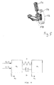
- FIG. 5 An illustration of an example of a suspension arrangement is shown in Figure 5 , where a wheel 52 and its associated bearing is attached to an upright element 54 that is attached to both a spring damping device 56 and to a suspension control arm 58. Both the suspension control arm 58 and spring damping device 56, for example a coil spring are attached to the main vehicle body.
- a vehicle controller 102 for controlling the operation of the in-wheel electric motors, for example controlling the torque generated by the in-wheel electric motors.
- the vehicle includes a battery for providing a power source for the in-wheel electric motors.
- the in-wheel electric motor is of the type having a set of coils being part of the stator for attachment to the vehicle, radially surrounded by a rotor carrying a set of magnets for attachment to a wheel.
- the present invention is applicable to other types of electric motors.
- the in-wheel electric motor 40 includes a stator 252 comprising a rear portion 230 forming a first part of the housing of the assembly, and a heat sink and drive arrangement 231 comprising multiple coils and electronics to drive the coils.
- the coil drive arrangement 231 is fixed to the rear portion 230 to form the stator 252 which may then be fixed to a vehicle and does not rotate during use.
- the coils themselves are formed on tooth laminations which together with the drive arrangement 231 and rear portion 230 form the stator 252.
- a rotor 240 comprises a front portion 220 and a cylindrical portion 221 forming a cover, which substantially surrounds the stator 252.
- the rotor includes a plurality of magnets 242 arranged around the inside of the cylindrical portion 221. The magnets are thus in close proximity to the coils on the assembly 231 so that magnetic fields generated by the coils in the assembly 231 cooperate with the magnets 242 arranged around the inside of the cylindrical portion 221 of the rotor 240 to cause the rotor 240 to rotate.
- the rotor 240 is attached to the stator 252 by a bearing block 223.
- the bearing block 223 can be a standard bearing block as would be used in a vehicle to which this motor assembly is to be fitted with the bearing block being mounted to a suspension device, for example as described above.
- the bearing block comprises two parts, a first part fixed to the stator and a second part fixed to the rotor.
- the bearing block is fixed to a central portion 233 of the wall 230 of the stator 252 and also to a central portion 225 of the housing wall 220 of the rotor 240.
- the rotor 240 is thus rotationally fixed to the vehicle with which it is to be used via the bearing block 223 at the central portion 225 of the rotor 240.
- the wheel bolts may be fitted through the central portion 225 of the rotor through into the bearing block itself.
- Figure 6 shows an exploded view of the same assembly as Figure 4 from the opposite side showing the stator 252 comprising the rear stator wall 230 and coil and electronics assembly 231.
- the rotor 240 comprises the outer rotor wall 220 and circumferential wall 221 within which magnets 242 are circumferentially arranged.
- the stator 252 is connected to the rotor 240 via the bearing block at the central portions of the rotor and stator walls.
- circuit boards 80 carrying control electronics otherwise known as motor drive controllers or inverters.
- a V shaped seal 350 is provided between the circumferential wall 221 of the rotor and the outer edge of the stator housing 230.
- the rotor also includes a focussing ring and magnets 227 for rotor position sensing, which in conjunction with sensors mounted on the stator allows for an accurate position determination of the rotor relative to the stator to be made.
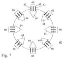
- FIG. 7 schematically shows an example of an electric motor 40 in accordance with an embodiment of this invention.
- the motor is generally circular.
- embodiments of this invention can employ other topologies.
- a linear arrangement of coils for producing linear movement is envisaged.
- the motor 40 in this example includes 8 coil sets 60 with each coil set 60 having three coil sub-sets 61, 62, 63 that are coupled to a respective control device 64, where each control device 64 and respective coil sub-sets form a three phase logical or sub electric motor that can be controlled independently of the other sub motors.
- the control devices 64 drive their respective sub motor with a three phase voltage supply, thereby allowing the respective coil sub-sets to generate a rotating magnetic field.
- each coil set 60 describes each coil set 60 as having three coil sub-sets 61, 62, 63, the present invention is not limited by this and it would be appreciated that each coil set 60 could have two or more coil sub-sets.
- the present embodiment describes an electric motor having eight coil sets 60 (i.e. eight sub motors) the motor could have two or more coil sets with associated control devices (i.e. two or more sub motors).
- Each control device includes a three phase bridge inverter which, as is well known to a person skilled in the art, contains six switches.
- the three phase bridge inverter is coupled to the three subset coils of a coil set 60 to form a three phase electric motor configuration.
- the motor includes eight three phase sub-motors, where each three phase sub-motor includes a control device 64 coupled to the three sub-set coils of a coil set 60.
- each three phase bridge inverter is arranged to provide PWM voltage control across the respective coil sub-sets 61, 62, 63 to provide a required torque for the respective sub-motors.
- the three phase bridge switches of a control device 64 are arranged to apply a single voltage phase across each of the coil sub-sets 61, 62, 63.
- the in-wheel electric motor described in the present embodiment includes a plurality of logical sub-motors
- the electric motor may be of a conventional design without the use of logical sub-motors.
- each control device 80 is substantially wedge-shaped. This shape allows multiple control devices 80 to be located adjacent each other within the motor, forming a fan-like arrangement.
- the control device 80 switches can include semiconductor devices such as MOSFETs or IGBTs.
- the switches comprise IGBTs.
- any suitable known switching circuit can be employed for controlling the current.
- One well known example of such a switching circuit is the three phase bridge circuit having six switches configured to drive a three phase electric motor. The six switches are configured as three parallel sets of two switches, where each pair of switches is placed in series and forms a leg of the three phase bridge circuit.
- the vehicle controller 102 In response to an acceleration or braking demand from a driver of the vehicle the vehicle controller 102 is arranged to control current flow in the respective motors via the respective control device 80, thereby controlling the torque generated by the respective motors. Additionally the vehicle controller 102 is arranged to modulate the torque being applied by the respective motors dependent on the relative longitudinal or vertical movement or displacement of the wheel 101 with respect to the respective mounting points at which the respective suspension devices are mounted to the vehicle 100. In other words, the vehicle controller 102 is arranged to modulate the torque being applied by the respective motors dependent on the relative longitudinal or vertical movement or displacement of the vehicle's unsprung and sprung masses.
- the relative movement or displacement of the vehicle's unsprung and sprung mass can be determined by any suitable means, for example via the use of accelerometers, or velocity, force, position or deflection sensors.
- the vehicle controller 102 is arranged to vary the torque being applied by the respective in-wheel electric motors to the respective wheels resulting in a longitudinal force F t (t) at the wheel, which in turn modifies the longitudinal behaviour of the suspension.
- a displacement between the wheel and the vehicles body occurs.
- the vehicle controller 102 identifies from sensor information that there is relative movement between the wheel 101 and the vehicles body (i.e. that a displacement has occurred) and the vehicle controller 102 arranges for a positive torque to be applied by the respective in-wheel electric motor, thereby exerting a positive damping force at the wheel.
- vertical movement of the wheel can be used as an indication of longitudinal movement of the vehicle's wheel and accordingly can be used to determine a suitable torque for generating a longitudinal force at the wheel for modifying the longitudinal behaviour of the suspension.
- Figure 7 illustrates a simplified quarter-car two degree of freedom model that includes the additional longitudinal force F t (t) generated at a wheel 101 by a respective electric motor, where m u represents the unsprung mass and m s represents the sprung mass.
- the longitudinal compliance of the suspension is represented by the spring-damper system with spring constant k and damping constant b.
- the positions of the unsprung and sprung masses in the longitudinal direction are shown as x u and x s respectively.
- the longitudinal component of the force imparted by the road surface on the unsprung mass is shown as F r (t).
- the torque generated by the respective in-wheel electric motors is determined using a control algorithm that calculates the torque based on the respective longitudinal movement of the unsprung mass and sprung mass of the vehicle 100 such that the damping effect provided by the suspension device is varied according to preferred damping characteristics.
- Any suitable means for determining the relative movement of the unsprung mass and sprung mass may be used, for example this may be changes in velocity, changes in displacement, or changes in acceleration.
- the torque determined from the control algorithm is modulated onto the existing torque generated by the in-wheel electric motors that results from a throttle demand generated by a driver of the vehicle 100.
- any suitable control algorithm may be used, for example PID (Proportional Integral Differential) control in which the relative speed, acceleration or displacement of the unsprung and sprung masses is controlled to a target value by applying torque that is a linear sum of three terms relating to the deviation from the target value, the integral of the deviation from the target value and the differential of the deviation from the target value respectively.
- PID Proportional Integral Differential
- the vehicle controller 102 may have access to a table that equates a specific torque value with a specific relative movement between the sprung and unsprung masses.
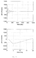
- Figure 9 illustrates a plot of change in acceleration resulting from a longitudinal acceleration being applied to an actively damped suspension according to an embodiment according to the present invention.
- the torque applied by the electric motor should be instantaneous in response to the change in relative speed, acceleration or displacement of the sprung and unsprung masses.
- the total delay should not exceed a few milliseconds.
- the vehicle controller 102 is arranged to avoid generating torque to oppose driver torque demands.
- the active damping torque can be corrected accordingly.
- the vehicle controller 102 is arranged to modulate the torque to provide active suspension torque only in response to large relative speeds or displacement of wheel and body that are indicative of a harsh impact but would not occur in normal acceleration or deceleration. That is to say, the vehicle controller 102 is arranged to only modulate the torque of an electric motor when the relative speed, acceleration or displacement of the sprung and unsprung masses exceeds a predetermined value.
- a strongly damped underlying passive suspension can be used with a high damping coefficient.
- the vehicle controller 102 would be arranged to reduce the damping coefficient upon the initial longitudinal shock being applied by opposing the large value of jerk during the impact. After the initial shock has occurred the damping effect provided by the electric motor is reduced, thereby relying on the strong damping coefficient provided by the underlying passive suspension.
Landscapes
- Engineering & Computer Science (AREA)
- Mechanical Engineering (AREA)
- Transportation (AREA)
- Chemical & Material Sciences (AREA)
- Combustion & Propulsion (AREA)
- Automation & Control Theory (AREA)
- Power Engineering (AREA)
- Vehicle Body Suspensions (AREA)
- Control Of Driving Devices And Active Controlling Of Vehicle (AREA)
- Electric Propulsion And Braking For Vehicles (AREA)
Description
- The present invention relates to a suspension control system, in particular a suspension control system for a vehicle having a wheel driven by an electric motor.
- The suspension system of a vehicle has two principle functions, first to isolate the vehicle body and consequently the vehicle's passengers from road inputs, and second to improve the vehicle's road holding by reducing the load variation between the wheels of the vehicle and the ground.
- The behaviour of a vehicle's suspension system can be characterised in terms of the suspension system's vertical and longitudinal compliance.
- The vertical compliance of vehicle suspension systems is typically created by spring-damper systems that are tuned to provide a good compromise between passenger comfort and handling performance. The springs are chosen to have a resonant frequency of the sprung mass between about 0.7 Hz and 2 Hz. Lower resonant frequencies induce travel sickness whereas higher frequencies reduce the suppression of road inputs. Stiff damping results in a harsh ride but soft damping results in long lasting car body motion following disturbance and large load variation between wheel and road.
- In contrast, to maintain good wheel control the longitudinal compliance of a vehicle is generally significantly stiffer than that of the vertical compliance; otherwise the torque provided by the brake or drive-train acts on the vehicle body through a soft suspension system, thereby reducing the driver's ability to maintain vehicle control. As a consequence the longitudinal compliance of a vehicle's suspension system is typically provided primarily by bushings.
- As with the vertical compliance of a suspension system, there is also a compromise with respect to the longitudinal compliance between passenger comfort, which is increased by softening the damping, and the need to dampen oscillations in the cabin to maintain good vehicle control.
- For example, a road surface disturbance such as a pot-hole induces a longitudinal force impulse on a vehicle's wheel, where the longitudinal force causes an initial shock that is felt by the occupants of the vehicle followed by a vibration. Increasing the longitudinal stiffness increases the initial shock but reduces the duration of the subsequent vibration for a given road disturbance.
- The longitudinal behaviour of a suspension system can be illustrated with the simplified quarter-car two degree-of-freedom model shown in
Figure 1 . mu represents the unsprung mass, for example a wheel and associated parts, and ms represents the sprung mass, the quarter-car body. The longitudinal compliance of the suspension is represented by the spring-damper system with spring constant k and damping constant b. The positions of the unsprung and sprung mass in the longitudinal direction are shown as xu and xs respectively. The longitudinal component of the force imparted by the road surface on the unsprung mass is shown as Fr(t). - The motion of the sprung mass in response to an imperfect road surface generally determines the comfort of the vehicles passengers. The key features of motion associated with passenger discomfort are the magnitude and duration of the rate of change of acceleration, otherwise known as vehicle jerk, resulting from road surface imperfections.
- In response to a shock, such as that caused by a wheel of a vehicle hitting a pot-hole in a road surface, there is an initial high magnitude jerk followed by oscillations. Both of these features can be unpleasant to a passenger of a vehicle. However, whereas the optimum means for minimising the initial jerk requires weak damping, in contrast the optimum means for minimising the subsequent oscillations requires strong damping.
-
Figure 2 illustrates the conflict between the requirements for strong and weak damping with respect to longitudinal compliance for a passive suspension system, where theleft hand plot 20 inFigure 2 reflects rate of change of acceleration versus time for a strong damping system and the right hand plot 22 inFigure 2 reflects rate of change of acceleration versus time for a weak damping system. For the purposes of the plots illustrated inFigure 2 , the plots are based on the simplified quarter car two degree of freedom model illustrated inFigure 1 using the following parameters: mu=50 kg, ms=400 kg, k=444 N/mm. For the strong damping plots b=1.5 Ns/mm and for the weak damping plots b=0.3 Ns/mm. Both masses are initially moving at 15 m/s and a pot-hole strike is simulated by constructing Fr(t) as a half sinusoid ofduration 5 ms and amplitude 10000 N. This imparts an initial acceleration of about 200 m/s/s to the unsprung mass, i.e. the wheel. The plots illustrated inFigure 2 show the resulting jerk as a function of time of the sprung mass, i.e. the vehicle body. - The upper plots illustrated in
Figure 2 show that the weak damped system leads to a long-lasting longitudinal oscillation of the vehicle body whereas the strong damped system quickly suppresses oscillations after the initial impact. The lower plots show the same data on an expanded time-scale to show the rate of change of acceleration of the vehicle body shortly after the impact time. The maximum magnitude of the jerk in the strongly damped case is about 1100 m/s/s/s whereas it is about 700 m/s/s/s in the weakly damped case. This figure represents the initial shock felt by the occupants of the vehicle. - As such, a suspension system having a longitudinal compliance that is defined by either a strong or weak damper system fails to provide optimum vehicle control and vehicle passenger ride comfort.
- It is desirable to improve this situation.
-
WO 2010/131091 describes a sprung mass dampening control system for a vehicle that is arrange to dampen vibration in the longitudinal direction of the vehicle as a result of forces internal to the vehicle. - In accordance with an aspect of the present invention there is provided a suspension control system according to the accompanying claims.
- This provides the advantage of allowing the longitudinal compliance damping characteristics to be actively modified, where a longitudinal damping force applied to a wheel of a vehicle can be varied by modifying the torque applied to the wheel from an electric motor based on the relative movement of the wheel. For example, a weak damping force can initially be applied upon a longitudinal jerk first occurring with the damping force gradually being increased by modifying the torque applied to the wheel to apply further dampening to the subsequent oscillations. Accordingly, the present invention allows for the combination of the suppression of oscillations of the strong damping with the initial impact softness of the weakly damped case.
- As such, a vehicle can be provided with a softly damped longitudinal passive suspension system, which is used to minimise the initial shock felt by passengers of the vehicle resulting from a road surface disturbance, with an electric motor being used to modulate the torque applied to a wheel of the vehicle to strengthen the longitudinal damping after the initial shock to minimise the subsequent oscillations.
- The present invention will now be described by way of example, with reference to the accompanying drawings, in which:
-
Figure 1 illustrates a model for the longitudinal behaviour of a suspension system; -
Figure 2 illustrates the effect of an external longitudinal force on a suspension system having strong and weak damping; -
Figure 3 illustrates a vehicle according to an embodiment of the present invention; -
Figure 4 illustrates an exploded view of an electric motor as used in an embodiment of the present invention; -
Figure 5 illustrates an example of a passive suspension arrangement; -
Figure 6 illustrates an exploded view of the electric motor shown infigure 2 from an alternative angle; -
Figure 7 illustrates an example arrangement of coil sets for an electric motor according to an embodiment of the present invention; -
Figure 8 illustrates a model for the longitudinal behaviour of a suspension system according to an embodiment of the present invention; -
Figure 9 illustrates a plot of change in acceleration resulting from a longitudinal acceleration being applied to an actively damped suspension according to an embodiment according to the present invention. -
Figure 3 illustrates avehicle 100, for example a car or lorry, having fourwheels 101, where two wheels are located in the vehicles forward position in a near side and off side position respectively. Similarly, two additional wheels are located in the vehicles aft position in near side and off side positions respectively, as is typical for a conventional car configuration. However, as would be appreciated by a person skilled in the art, the vehicle may have any number of wheels. - Incorporated within each
wheel 101 is an in-wheel electric motor, as described in detail below. Although the current embodiment describes a vehicle having an in-wheel electric motor associated with eachwheel 101, as would be appreciated by a person skilled in the art only a subset of thewheels 101 may have an associated in-wheel electric motor. For example, for a four wheeled vehicle only the front two wheels may have associated in-wheel motors or alternately only the rear two wheels may have associated in-wheel motors or only a single wheel may have an associated in-wheel electric motor. Although the present embodiment describes the wheels being driven by a respective in-wheel electric motor, the respective electric motors may be located in any position within the vehicle. - Each wheel and associated in-wheel electric motor is coupled to a suspension device, for example a suspension arm, which in turn is coupled to a fixed mounting point on a part of the main vehicle body, for example the vehicle chassis. The suspension device provides isolation between the body of the vehicle and road inputs applied to the wheels, where the wheels and electric motors correspond to the vehicles unsprung mass and the vehicles body corresponds to the vehicles sprung mass.
- An illustration of an example of a suspension arrangement is shown in
Figure 5 , where awheel 52 and its associated bearing is attached to anupright element 54 that is attached to both aspring damping device 56 and to asuspension control arm 58. Both thesuspension control arm 58 andspring damping device 56, for example a coil spring are attached to the main vehicle body. - Coupled to each in-wheel electric motor is a
vehicle controller 102 for controlling the operation of the in-wheel electric motors, for example controlling the torque generated by the in-wheel electric motors. - Additionally, the vehicle includes a battery for providing a power source for the in-wheel electric motors.
- For the purpose of illustration, the in-wheel electric motor is of the type having a set of coils being part of the stator for attachment to the vehicle, radially surrounded by a rotor carrying a set of magnets for attachment to a wheel. However, as would be appreciated by a person skilled in the art, the present invention is applicable to other types of electric motors.
- As illustrated in
figure 4 , the in-wheelelectric motor 40 includes astator 252 comprising arear portion 230 forming a first part of the housing of the assembly, and a heat sink and drivearrangement 231 comprising multiple coils and electronics to drive the coils. Thecoil drive arrangement 231 is fixed to therear portion 230 to form thestator 252 which may then be fixed to a vehicle and does not rotate during use. The coils themselves are formed on tooth laminations which together with thedrive arrangement 231 andrear portion 230 form thestator 252. - A
rotor 240 comprises afront portion 220 and acylindrical portion 221 forming a cover, which substantially surrounds thestator 252. The rotor includes a plurality ofmagnets 242 arranged around the inside of thecylindrical portion 221. The magnets are thus in close proximity to the coils on theassembly 231 so that magnetic fields generated by the coils in theassembly 231 cooperate with themagnets 242 arranged around the inside of thecylindrical portion 221 of therotor 240 to cause therotor 240 to rotate. - The
rotor 240 is attached to thestator 252 by abearing block 223. Thebearing block 223 can be a standard bearing block as would be used in a vehicle to which this motor assembly is to be fitted with the bearing block being mounted to a suspension device, for example as described above. The bearing block comprises two parts, a first part fixed to the stator and a second part fixed to the rotor. The bearing block is fixed to a central portion 233 of thewall 230 of thestator 252 and also to a central portion 225 of thehousing wall 220 of therotor 240. Therotor 240 is thus rotationally fixed to the vehicle with which it is to be used via the bearing block 223 at the central portion 225 of therotor 240. This has an advantage in that a wheel rim and tyre can then be fixed to therotor 240 at the central portion 225 using the normal wheel bolts to fix the wheel rim to the central portion of the rotor and consequently firmly onto the rotatable side of thebearing block 223. The wheel bolts may be fitted through the central portion 225 of the rotor through into the bearing block itself. With both therotor 240 and the wheel being mounted to the bearing block 223 there is a one to one correspondence between the angle of rotation of the rotor and the wheel. -
Figure 6 shows an exploded view of the same assembly asFigure 4 from the opposite side showing thestator 252 comprising therear stator wall 230 and coil andelectronics assembly 231. Therotor 240 comprises theouter rotor wall 220 andcircumferential wall 221 within whichmagnets 242 are circumferentially arranged. As previously described, thestator 252 is connected to therotor 240 via the bearing block at the central portions of the rotor and stator walls. - Additionally shown in
Figure 4 arecircuit boards 80 carrying control electronics, otherwise known as motor drive controllers or inverters. - A V shaped
seal 350 is provided between thecircumferential wall 221 of the rotor and the outer edge of thestator housing 230. - The rotor also includes a focussing ring and
magnets 227 for rotor position sensing, which in conjunction with sensors mounted on the stator allows for an accurate position determination of the rotor relative to the stator to be made. -
Figure 7 schematically shows an example of anelectric motor 40 in accordance with an embodiment of this invention. In this example, the motor is generally circular. However, it will be appreciated that embodiments of this invention can employ other topologies. For example a linear arrangement of coils for producing linear movement is envisaged. - The
motor 40 in this example includes 8 coil sets 60 with each coil set 60 having threecoil sub-sets 61, 62, 63 that are coupled to arespective control device 64, where eachcontrol device 64 and respective coil sub-sets form a three phase logical or sub electric motor that can be controlled independently of the other sub motors. Thecontrol devices 64 drive their respective sub motor with a three phase voltage supply, thereby allowing the respective coil sub-sets to generate a rotating magnetic field. Although the present embodiment describes each coil set 60 as having threecoil sub-sets 61, 62, 63, the present invention is not limited by this and it would be appreciated that each coil set 60 could have two or more coil sub-sets. Equally, although the present embodiment describes an electric motor having eight coil sets 60 (i.e. eight sub motors) the motor could have two or more coil sets with associated control devices (i.e. two or more sub motors). - Each control device includes a three phase bridge inverter which, as is well known to a person skilled in the art, contains six switches. The three phase bridge inverter is coupled to the three subset coils of a coil set 60 to form a three phase electric motor configuration. Accordingly, as stated above, the motor includes eight three phase sub-motors, where each three phase sub-motor includes a
control device 64 coupled to the three sub-set coils of acoil set 60. - Under the control of the
vehicle controller 102 each three phase bridge inverter is arranged to provide PWM voltage control across therespective coil sub-sets 61, 62, 63 to provide a required torque for the respective sub-motors. - For a given coil set the three phase bridge switches of a
control device 64 are arranged to apply a single voltage phase across each of thecoil sub-sets 61, 62, 63. - Although the in-wheel electric motor described in the present embodiment includes a plurality of logical sub-motors, the electric motor may be of a conventional design without the use of logical sub-motors.
- In this embodiment, each
control device 80 is substantially wedge-shaped. This shape allowsmultiple control devices 80 to be located adjacent each other within the motor, forming a fan-like arrangement. - The
control device 80 switches can include semiconductor devices such as MOSFETs or IGBTs. In the present example, the switches comprise IGBTs. However, any suitable known switching circuit can be employed for controlling the current. One well known example of such a switching circuit is the three phase bridge circuit having six switches configured to drive a three phase electric motor. The six switches are configured as three parallel sets of two switches, where each pair of switches is placed in series and forms a leg of the three phase bridge circuit. - In response to an acceleration or braking demand from a driver of the vehicle the
vehicle controller 102 is arranged to control current flow in the respective motors via therespective control device 80, thereby controlling the torque generated by the respective motors. Additionally thevehicle controller 102 is arranged to modulate the torque being applied by the respective motors dependent on the relative longitudinal or vertical movement or displacement of thewheel 101 with respect to the respective mounting points at which the respective suspension devices are mounted to thevehicle 100. In other words, thevehicle controller 102 is arranged to modulate the torque being applied by the respective motors dependent on the relative longitudinal or vertical movement or displacement of the vehicle's unsprung and sprung masses. - The relative movement or displacement of the vehicle's unsprung and sprung mass can be determined by any suitable means, for example via the use of accelerometers, or velocity, force, position or deflection sensors.
- Based on the relative movement or displacement of the vehicle's unsprung mass and sprung mass the
vehicle controller 102 is arranged to vary the torque being applied by the respective in-wheel electric motors to the respective wheels resulting in a longitudinal force Ft(t) at the wheel, which in turn modifies the longitudinal behaviour of the suspension. - For example, for a
vehicle 100 moving in a positive x direction, when awheel 101 of thevehicle 100 strikes a pot-hole a displacement between the wheel and the vehicles body occurs. As thewheel 101 starts to recess towards the vehicle body thevehicle controller 102 identifies from sensor information that there is relative movement between thewheel 101 and the vehicles body (i.e. that a displacement has occurred) and thevehicle controller 102 arranges for a positive torque to be applied by the respective in-wheel electric motor, thereby exerting a positive damping force at the wheel. - Additionally, vertical movement of the wheel can be used as an indication of longitudinal movement of the vehicle's wheel and accordingly can be used to determine a suitable torque for generating a longitudinal force at the wheel for modifying the longitudinal behaviour of the suspension.
- Similar to
Figure 1 ,Figure 7 illustrates a simplified quarter-car two degree of freedom model that includes the additional longitudinal force Ft(t) generated at awheel 101 by a respective electric motor, where mu represents the unsprung mass and ms represents the sprung mass. The longitudinal compliance of the suspension is represented by the spring-damper system with spring constant k and damping constant b. The positions of the unsprung and sprung masses in the longitudinal direction are shown as xu and xs respectively. The longitudinal component of the force imparted by the road surface on the unsprung mass is shown as Fr(t). - Preferably the torque generated by the respective in-wheel electric motors is determined using a control algorithm that calculates the torque based on the respective longitudinal movement of the unsprung mass and sprung mass of the
vehicle 100 such that the damping effect provided by the suspension device is varied according to preferred damping characteristics. Any suitable means for determining the relative movement of the unsprung mass and sprung mass may be used, for example this may be changes in velocity, changes in displacement, or changes in acceleration. For the purposes of the present embodiment the control algorithm used is based upon the Sky-Hook technique where the torque applied to the wheel is determined from the equation T = b 2(ẋs - ẋu )r, where b 2 is an active damping coefficient of value 1.2 Ns/mm, ẋs is the velocity of the sprung mass, ẋu is the velocity of the unsprung mass and r is the rolling radius of the wheel. The torque determined from the control algorithm is modulated onto the existing torque generated by the in-wheel electric motors that results from a throttle demand generated by a driver of thevehicle 100. - Although the present embodiment uses a control algorithm based on the Sky-Hook technique, any suitable control algorithm may be used, for example PID (Proportional Integral Differential) control in which the relative speed, acceleration or displacement of the unsprung and sprung masses is controlled to a target value by applying torque that is a linear sum of three terms relating to the deviation from the target value, the integral of the deviation from the target value and the differential of the deviation from the target value respectively.
- Alternatively, other means for determining torque values may be used, for example the
vehicle controller 102 may have access to a table that equates a specific torque value with a specific relative movement between the sprung and unsprung masses. -
Figure 9 illustrates a plot of change in acceleration resulting from a longitudinal acceleration being applied to an actively damped suspension according to an embodiment according to the present invention. - The change in acceleration plot illustrated in
Figure 9 is based on a suspension system where the passive suspension component has a damping constant b=0.3 Ns/mm with thevehicle controller 102 being arranged to modulate the respective in-wheel electric motor to increase damping after the initial shock, thereby combining the performance of a strongly damped suspension with the initial impact softness of the weakly damped passive suspension. The damping performance of the active suspension system is equivalent to that of a passive suspension of b=1.5 Ns/mm, this being the sum of the passive damping coefficient and the equivalent Sky-Hook damping coefficient b2. However, the initial shock transferred to the body of the vehicle is equivalent to that of a soft passive suspension system with a damping constant b=0.3 Ns/mm - Ideally the torque applied by the electric motor should be instantaneous in response to the change in relative speed, acceleration or displacement of the sprung and unsprung masses. However, in a practical system there will be delays resulting from the sensors, the
vehicle controller 102 and the electric motor and in the communication between these components that result in an overall delayed response of the system. Preferably the total delay should not exceed a few milliseconds. - In the absence of road disturbances the relative speed of the vehicles sprung and unsprung masses will change as a result of a change in applied torque demanded by the driver. To avoid the active suspension system working against the torque demands made by the driver of the
vehicle 100, preferably thevehicle controller 102 is arranged to avoid generating torque to oppose driver torque demands. However, as the driver torque demand is known and the characteristics of the longitudinal compliance of the wheel will be known, the active damping torque can be corrected accordingly. Preferably thevehicle controller 102 is arranged to modulate the torque to provide active suspension torque only in response to large relative speeds or displacement of wheel and body that are indicative of a harsh impact but would not occur in normal acceleration or deceleration. That is to say, thevehicle controller 102 is arranged to only modulate the torque of an electric motor when the relative speed, acceleration or displacement of the sprung and unsprung masses exceeds a predetermined value. - Although the above embodiment is based on the
vehicle controller 102 being used to increase the damping coefficient of the suspension system after an initial longitudinal shock has been applied to a vehicle's wheel, in an alternative embodiment a strongly damped underlying passive suspension can be used with a high damping coefficient. In this embodiment thevehicle controller 102 would be arranged to reduce the damping coefficient upon the initial longitudinal shock being applied by opposing the large value of jerk during the impact. After the initial shock has occurred the damping effect provided by the electric motor is reduced, thereby relying on the strong damping coefficient provided by the underlying passive suspension.
Claims (10)
- A suspension control system for a vehicle (100) having a vehicle body, a wheel (101, 52) and a suspension device (58), wherein the wheel (101, 52) is mounted to the suspension device (58) and the suspension device (58) is mounted to the vehicle body at a mounting point on the vehicle body with an electric motor (40) being arranged to apply to the wheel a torque for driving the wheel (101, 52),
characterized in that
the suspension control system comprises a controller (102) arranged to modulate a torque applied to the wheel (101, 52) by the electric motor (40) to dampen longitudinal movement of the wheel (101, 52) relative to the mounting point on the vehicle body based on the relative longitudinal or vertical movement of the wheel (101, 52) with respect to the mounting point on the vehicle body. - A suspension control system according to claim 1, wherein the controller (102) is arranged to modulate the torque applied to the wheel (101, 52) to increase movement of wheel relative to the mounting point on the vehicle body.
- A suspension control system according to claim 1 or 2 wherein the controller (52) is arranged to modulate torque applied to the wheel (101, 52) based on b 2(ẋs - ẋu )r, where b 2 is a damping coefficient, ẋs is the velocity of sprung mass of the vehicle, ẋu is the velocity of the unsprung mass of the vehicle and r is the rolling radius of the wheel.
- A suspension control system according to any one of the preceding claims, wherein the controller (102) is arranged to modulate torque applied to the wheel (101, 52) if the rate of change of longitudinal acceleration of the wheel relative to the mounting point exceeds a predetermined value.
- A suspension control system according to any one of the preceding claims, wherein the controller (102) is arranged to modulate torque applied to the wheel (101, 52) based on the rate of change of longitudinal acceleration of the wheel with respect to the mounting point on the vehicle body.
- A suspension control system according to any one of claims 1 to 5, wherein the controller (102) is arranged to modulate torque applied to the wheel (101, 52) based on the rate of change of longitudinal velocity of the wheel with respect to the mounting point on the vehicle body.
- A vehicle (100) comprising a suspension control system according to any one of the preceding claims.
- A vehicle (100) according to claim 7, further comprising a sensor for determining the relative longitudinal movement of the wheel relative to the mounting point.
- A vehicle (100) according to claim 7 or 8, wherein the electric motor is an in-wheel electric motor
- A vehicle (100) according to any one of claims 7 to 9, further comprising a plurality of wheels (101, 52) mounted to the vehicle via a respective suspension device (58) mounted to a mounting point on the vehicle body, wherein at least two of the wheels (101, 52) are arranged to be driven by respective electric motors (40) and the controller (102) is arranged to modulate the torque of the respective electric motors (40) based on the relative longitudinal movement of the wheel being driven by the respective electric motor with respect to the respective mounting points on the vehicle body.
Applications Claiming Priority (2)
| Application Number | Priority Date | Filing Date | Title |
|---|---|---|---|
| GB1103463.4A GB2479431B (en) | 2011-03-01 | 2011-03-01 | A suspension control system |
| PCT/IB2012/050570 WO2012117305A1 (en) | 2011-03-01 | 2012-02-08 | A suspension control system |
Publications (2)
| Publication Number | Publication Date |
|---|---|
| EP2681061A1 EP2681061A1 (en) | 2014-01-08 |
| EP2681061B1 true EP2681061B1 (en) | 2016-11-23 |
Family
ID=43904357
Family Applications (1)
| Application Number | Title | Priority Date | Filing Date |
|---|---|---|---|
| EP12706929.2A Active EP2681061B1 (en) | 2011-03-01 | 2012-02-08 | A suspension control system |
Country Status (6)
| Country | Link |
|---|---|
| US (1) | US9434229B2 (en) |
| EP (1) | EP2681061B1 (en) |
| JP (1) | JP6173221B2 (en) |
| CN (1) | CN103534112B (en) |
| GB (1) | GB2479431B (en) |
| WO (1) | WO2012117305A1 (en) |
Families Citing this family (32)
| Publication number | Priority date | Publication date | Assignee | Title |
|---|---|---|---|---|
| EP2577027A2 (en) | 2010-06-03 | 2013-04-10 | Polaris Industries Inc. | Electronic throttle control |
| JP2013095309A (en) * | 2011-11-02 | 2013-05-20 | Ntn Corp | Suspension system for in-wheel motor vehicle |
| US9205717B2 (en) | 2012-11-07 | 2015-12-08 | Polaris Industries Inc. | Vehicle having suspension with continuous damping control |
| CA2890996C (en) | 2012-11-07 | 2023-03-21 | Polaris Industries Inc. | Vehicle having suspension with continuous damping control |
| US9561715B2 (en) * | 2012-11-16 | 2017-02-07 | Deere & Company | Wheel hub with electric motor |
| WO2016069405A2 (en) | 2014-10-31 | 2016-05-06 | Polaris Industries Inc. | System and method for controlling a vehicle |
| JP6248919B2 (en) * | 2014-12-18 | 2017-12-20 | トヨタ自動車株式会社 | Braking force control device for vehicle |
| CN118849684A (en) | 2015-05-15 | 2024-10-29 | 北极星工业有限公司 | Multi-purpose vehicles |
| JP2017034816A (en) * | 2015-07-30 | 2017-02-09 | トヨタ自動車株式会社 | Electric vehicle |
| WO2017018180A1 (en) * | 2015-07-30 | 2017-02-02 | 本田技研工業株式会社 | Vehicle |
| US10476360B2 (en) | 2016-09-13 | 2019-11-12 | Indigo Technologies, Inc. | Axial flux motor having rotatably coupled coil stator assemblies and methods of using same |
| CA3043481C (en) | 2016-11-18 | 2022-07-26 | Polaris Industries Inc. | Vehicle having adjustable suspension |
| US10406884B2 (en) | 2017-06-09 | 2019-09-10 | Polaris Industries Inc. | Adjustable vehicle suspension system |
| KR102478125B1 (en) * | 2017-11-24 | 2022-12-16 | 현대자동차주식회사 | Control method and system for motor drive vehicle |
| US10493990B2 (en) | 2017-12-15 | 2019-12-03 | Tenneco Automotive Operating Company Inc. | Systems and methods for ride control blending in electric vehicles |
| US10946736B2 (en) | 2018-06-05 | 2021-03-16 | Polaris Industries Inc. | All-terrain vehicle |
| US10987987B2 (en) | 2018-11-21 | 2021-04-27 | Polaris Industries Inc. | Vehicle having adjustable compression and rebound damping |
| CA3299418A1 (en) | 2019-04-30 | 2026-03-02 | Polaris Industries Inc. | Vehicle with removable final drive |
| US11691674B2 (en) | 2020-05-15 | 2023-07-04 | Polaris Industries Inc. | Off-road vehicle |
| US12187127B2 (en) | 2020-05-15 | 2025-01-07 | Polaris Industries Inc. | Off-road vehicle |
| CN120735865A (en) | 2020-05-20 | 2025-10-03 | 北极星工业有限公司 | System and method for adjustable suspension for off-road recreational vehicle |
| MX2022015902A (en) | 2020-07-17 | 2023-01-24 | Polaris Inc | Adjustable suspensions and vehicle operation for off-road recreational vehicles. |
| GB2597457B (en) * | 2020-07-21 | 2023-02-01 | Jaguar Land Rover Ltd | Vehicle active suspension control system and method |
| WO2022042852A1 (en) * | 2020-08-28 | 2022-03-03 | Volvo Truck Corporation | A system and a method for counteracting cabin vibrations |
| US11654780B2 (en) | 2020-12-17 | 2023-05-23 | Consolidated Metco, Inc. | Vehicle electronic control unit and method |
| US12005752B2 (en) * | 2021-01-28 | 2024-06-11 | Volvo Car Corporation | Limiting vehicle damper jerk |
| US12128726B2 (en) * | 2021-01-28 | 2024-10-29 | Volvo Car Corporation | Rear damper adjustment |
| DE112022001448T5 (en) | 2021-03-08 | 2024-01-25 | DRiV Automotive Inc. | METHOD FOR DAMPING VIBRATIONS OF THE LONGITUDINAL ACCELERATION OF A VEHICLE BODY |
| KR102568045B1 (en) * | 2021-11-03 | 2023-08-18 | 주식회사 현대케피코 | Method and apparatus for optimal control of driving torque for smooth ride on uneven road |
| MX2023006716A (en) | 2022-06-13 | 2023-12-14 | Polaris Inc | POWER TRAIN FOR UTILITY VEHICLE. |
| USD1067123S1 (en) | 2023-01-20 | 2025-03-18 | Polaris Industries Inc. | Off-road vehicle |
| USD1120805S1 (en) | 2023-06-29 | 2026-03-31 | Polaris Industries Inc. | Body assembly for an off-road vehicle |
Family Cites Families (21)
| Publication number | Priority date | Publication date | Assignee | Title |
|---|---|---|---|---|
| US3842753A (en) * | 1973-08-03 | 1974-10-22 | Rohr Industries Inc | Suspension dampening for a surface support vehicle by magnetic means |
| JP3280392B2 (en) * | 1991-04-01 | 2002-05-13 | アイシン・エィ・ダブリュ株式会社 | Driving force control device for electric vehicle |
| US5438514A (en) * | 1991-12-27 | 1995-08-01 | Atsugi Unisia Corporation | Apparatus for controlling damping coefficient for vehicular shock absorber |
| JPH06211026A (en) * | 1991-12-27 | 1994-08-02 | Unisia Jecs Corp | Vehicle suspension |
| JPH0692126A (en) * | 1992-09-16 | 1994-04-05 | Nippondenso Co Ltd | Damping force variable shock absorber control device |
| JPH106731A (en) * | 1996-06-21 | 1998-01-13 | Nissan Motor Co Ltd | Vehicle suspension control device |
| JP4113506B2 (en) * | 2003-09-30 | 2008-07-09 | トヨタ自動車株式会社 | Wheel support device |
| WO2006062125A1 (en) * | 2004-12-09 | 2006-06-15 | Equos Research Co., Ltd. | Wheel supporting and driving device |
| GB2459061B (en) * | 2006-07-13 | 2010-07-28 | Qed Group Ltd | Electric motors |
| JP2008308142A (en) * | 2007-05-15 | 2008-12-25 | Nissan Motor Co Ltd | Vehicle attitude control device when stopped |
| JP4935573B2 (en) * | 2007-08-10 | 2012-05-23 | トヨタ自動車株式会社 | Suspension characteristics estimation device |
| JP2009137545A (en) * | 2007-12-10 | 2009-06-25 | Toyota Motor Corp | Damping force control device |
| JP5036601B2 (en) * | 2008-03-07 | 2012-09-26 | トヨタ自動車株式会社 | Vehicle damping force control device |
| JP2010158960A (en) * | 2009-01-07 | 2010-07-22 | Honda Motor Co Ltd | Travel situation notification device |
| JP5113098B2 (en) * | 2009-01-23 | 2013-01-09 | 日立オートモティブシステムズ株式会社 | Vehicle rollover prevention control device and vehicle rollover prevention control method |
| JP5310142B2 (en) * | 2009-03-14 | 2013-10-09 | 日産自動車株式会社 | Vehicle driving force control device |
| JP2010247652A (en) * | 2009-04-15 | 2010-11-04 | Toyota Motor Corp | Vehicle power supply system |
| JP5444111B2 (en) * | 2009-05-13 | 2014-03-19 | トヨタ自動車株式会社 | Vehicle sprung mass damping control device |
| JP2011016382A (en) * | 2009-07-07 | 2011-01-27 | Toyota Motor Corp | Damping force control device of vehicle |
| CN101716954B (en) * | 2009-11-24 | 2011-12-21 | 深圳职业技术学院 | Electric automobile with independently steered and driven wheels and steering and drive control method thereof |
| CN101973307B (en) * | 2010-10-19 | 2013-01-23 | 吉林大学 | Main pin zero bias wire-controlled independent driven and steering automobile running mechanism and electric vehicle |
-
2011
- 2011-03-01 GB GB1103463.4A patent/GB2479431B/en active Active
-
2012
- 2012-02-08 CN CN201280021317.2A patent/CN103534112B/en active Active
- 2012-02-08 JP JP2013555953A patent/JP6173221B2/en not_active Expired - Fee Related
- 2012-02-08 EP EP12706929.2A patent/EP2681061B1/en active Active
- 2012-02-08 US US14/002,707 patent/US9434229B2/en active Active
- 2012-02-08 WO PCT/IB2012/050570 patent/WO2012117305A1/en not_active Ceased
Non-Patent Citations (1)
| Title |
|---|
| None * |
Also Published As
| Publication number | Publication date |
|---|---|
| JP6173221B2 (en) | 2017-08-02 |
| US20140058606A1 (en) | 2014-02-27 |
| CN103534112B (en) | 2016-05-11 |
| JP2014512996A (en) | 2014-05-29 |
| GB2479431B (en) | 2012-08-08 |
| GB201103463D0 (en) | 2011-04-13 |
| EP2681061A1 (en) | 2014-01-08 |
| WO2012117305A1 (en) | 2012-09-07 |
| CN103534112A (en) | 2014-01-22 |
| GB2479431A (en) | 2011-10-12 |
| US9434229B2 (en) | 2016-09-06 |
Similar Documents
| Publication | Publication Date | Title |
|---|---|---|
| US9434229B2 (en) | Suspension control system | |
| JP6267799B2 (en) | Damper and damper manufacturing method | |
| JP3722128B2 (en) | VEHICLE ELECTRIC SUSPENSION DEVICE AND MOTOR CONTROL METHOD FOR VEHICLE ELECTRONIC SUSPENSION DEVICE | |
| JP4935757B2 (en) | Vehicle suspension system | |
| US20160059658A1 (en) | Damper | |
| JP6481329B2 (en) | Sprung vibration suppression device for vehicle | |
| JP6345724B2 (en) | Vehicle suspension system | |
| Montazeri-Gh et al. | Investigation of the passive electromagnetic damper | |
| JP2019130979A (en) | Suspension structure for in-wheel motor drive device | |
| US20170028983A1 (en) | Electric vehicle | |
| JP4872792B2 (en) | Electric suspension system for vehicles | |
| JP4936075B2 (en) | Vehicle drive actuator | |
| JP2012076682A (en) | Suspension device | |
| JP5477262B2 (en) | Suspension device | |
| JP2009143472A (en) | Vehicle suspension system | |
| US20240181831A1 (en) | Suspension based active force damping for a vehicle | |
| Ichikawa et al. | Model building and experimental validation for regeneration of perpendicular vibration by in-wheel motor | |
| JP6187513B2 (en) | vehicle | |
| JP2016022811A (en) | vehicle | |
| US12509057B2 (en) | Device and method for reducing noise in an interior of a vehicle | |
| JP2009202623A (en) | Suspension system for vehicle | |
| JP2010143275A (en) | Suspension system for vehicle | |
| JP2005035489A (en) | Vehicle suspension system | |
| CN115674982A (en) | A Two-Stage Superposition Control Method for Electromechanical Suspension | |
| JP2013001139A (en) | Suspension device |
Legal Events
| Date | Code | Title | Description |
|---|---|---|---|
| PUAI | Public reference made under article 153(3) epc to a published international application that has entered the european phase |
Free format text: ORIGINAL CODE: 0009012 |
|
| 17P | Request for examination filed |
Effective date: 20130930 |
|
| AK | Designated contracting states |
Kind code of ref document: A1 Designated state(s): AL AT BE BG CH CY CZ DE DK EE ES FI FR GB GR HR HU IE IS IT LI LT LU LV MC MK MT NL NO PL PT RO RS SE SI SK SM TR |
|
| DAX | Request for extension of the european patent (deleted) | ||
| GRAP | Despatch of communication of intention to grant a patent |
Free format text: ORIGINAL CODE: EPIDOSNIGR1 |
|
| INTG | Intention to grant announced |
Effective date: 20160711 |
|
| GRAS | Grant fee paid |
Free format text: ORIGINAL CODE: EPIDOSNIGR3 |
|
| GRAA | (expected) grant |
Free format text: ORIGINAL CODE: 0009210 |
|
| AK | Designated contracting states |
Kind code of ref document: B1 Designated state(s): AL AT BE BG CH CY CZ DE DK EE ES FI FR GB GR HR HU IE IS IT LI LT LU LV MC MK MT NL NO PL PT RO RS SE SI SK SM TR |
|
| REG | Reference to a national code |
Ref country code: GB Ref legal event code: FG4D |
|
| REG | Reference to a national code |
Ref country code: CH Ref legal event code: EP |
|
| REG | Reference to a national code |
Ref country code: IE Ref legal event code: FG4D |
|
| REG | Reference to a national code |
Ref country code: AT Ref legal event code: REF Ref document number: 847516 Country of ref document: AT Kind code of ref document: T Effective date: 20161215 |
|
| REG | Reference to a national code |
Ref country code: DE Ref legal event code: R096 Ref document number: 602012025692 Country of ref document: DE |
|
| REG | Reference to a national code |
Ref country code: FR Ref legal event code: PLFP Year of fee payment: 6 |
|
| PG25 | Lapsed in a contracting state [announced via postgrant information from national office to epo] |
Ref country code: LV Free format text: LAPSE BECAUSE OF FAILURE TO SUBMIT A TRANSLATION OF THE DESCRIPTION OR TO PAY THE FEE WITHIN THE PRESCRIBED TIME-LIMIT Effective date: 20161123 |
|
| REG | Reference to a national code |
Ref country code: LT Ref legal event code: MG4D |
|
| REG | Reference to a national code |
Ref country code: NL Ref legal event code: MP Effective date: 20161123 |
|
| REG | Reference to a national code |
Ref country code: AT Ref legal event code: MK05 Ref document number: 847516 Country of ref document: AT Kind code of ref document: T Effective date: 20161123 |
|
| PG25 | Lapsed in a contracting state [announced via postgrant information from national office to epo] |
Ref country code: GR Free format text: LAPSE BECAUSE OF FAILURE TO SUBMIT A TRANSLATION OF THE DESCRIPTION OR TO PAY THE FEE WITHIN THE PRESCRIBED TIME-LIMIT Effective date: 20170224 Ref country code: LT Free format text: LAPSE BECAUSE OF FAILURE TO SUBMIT A TRANSLATION OF THE DESCRIPTION OR TO PAY THE FEE WITHIN THE PRESCRIBED TIME-LIMIT Effective date: 20161123 Ref country code: NL Free format text: LAPSE BECAUSE OF FAILURE TO SUBMIT A TRANSLATION OF THE DESCRIPTION OR TO PAY THE FEE WITHIN THE PRESCRIBED TIME-LIMIT Effective date: 20161123 Ref country code: SE Free format text: LAPSE BECAUSE OF FAILURE TO SUBMIT A TRANSLATION OF THE DESCRIPTION OR TO PAY THE FEE WITHIN THE PRESCRIBED TIME-LIMIT Effective date: 20161123 Ref country code: NO Free format text: LAPSE BECAUSE OF FAILURE TO SUBMIT A TRANSLATION OF THE DESCRIPTION OR TO PAY THE FEE WITHIN THE PRESCRIBED TIME-LIMIT Effective date: 20170223 |
|
| PG25 | Lapsed in a contracting state [announced via postgrant information from national office to epo] |
Ref country code: ES Free format text: LAPSE BECAUSE OF FAILURE TO SUBMIT A TRANSLATION OF THE DESCRIPTION OR TO PAY THE FEE WITHIN THE PRESCRIBED TIME-LIMIT Effective date: 20161123 Ref country code: PT Free format text: LAPSE BECAUSE OF FAILURE TO SUBMIT A TRANSLATION OF THE DESCRIPTION OR TO PAY THE FEE WITHIN THE PRESCRIBED TIME-LIMIT Effective date: 20170323 Ref country code: HR Free format text: LAPSE BECAUSE OF FAILURE TO SUBMIT A TRANSLATION OF THE DESCRIPTION OR TO PAY THE FEE WITHIN THE PRESCRIBED TIME-LIMIT Effective date: 20161123 Ref country code: AT Free format text: LAPSE BECAUSE OF FAILURE TO SUBMIT A TRANSLATION OF THE DESCRIPTION OR TO PAY THE FEE WITHIN THE PRESCRIBED TIME-LIMIT Effective date: 20161123 Ref country code: RS Free format text: LAPSE BECAUSE OF FAILURE TO SUBMIT A TRANSLATION OF THE DESCRIPTION OR TO PAY THE FEE WITHIN THE PRESCRIBED TIME-LIMIT Effective date: 20161123 Ref country code: BE Free format text: LAPSE BECAUSE OF NON-PAYMENT OF DUE FEES Effective date: 20170228 Ref country code: FI Free format text: LAPSE BECAUSE OF FAILURE TO SUBMIT A TRANSLATION OF THE DESCRIPTION OR TO PAY THE FEE WITHIN THE PRESCRIBED TIME-LIMIT Effective date: 20161123 Ref country code: PL Free format text: LAPSE BECAUSE OF FAILURE TO SUBMIT A TRANSLATION OF THE DESCRIPTION OR TO PAY THE FEE WITHIN THE PRESCRIBED TIME-LIMIT Effective date: 20161123 |
|
| PG25 | Lapsed in a contracting state [announced via postgrant information from national office to epo] |
Ref country code: CZ Free format text: LAPSE BECAUSE OF FAILURE TO SUBMIT A TRANSLATION OF THE DESCRIPTION OR TO PAY THE FEE WITHIN THE PRESCRIBED TIME-LIMIT Effective date: 20161123 Ref country code: SK Free format text: LAPSE BECAUSE OF FAILURE TO SUBMIT A TRANSLATION OF THE DESCRIPTION OR TO PAY THE FEE WITHIN THE PRESCRIBED TIME-LIMIT Effective date: 20161123 Ref country code: EE Free format text: LAPSE BECAUSE OF FAILURE TO SUBMIT A TRANSLATION OF THE DESCRIPTION OR TO PAY THE FEE WITHIN THE PRESCRIBED TIME-LIMIT Effective date: 20161123 Ref country code: DK Free format text: LAPSE BECAUSE OF FAILURE TO SUBMIT A TRANSLATION OF THE DESCRIPTION OR TO PAY THE FEE WITHIN THE PRESCRIBED TIME-LIMIT Effective date: 20161123 Ref country code: RO Free format text: LAPSE BECAUSE OF FAILURE TO SUBMIT A TRANSLATION OF THE DESCRIPTION OR TO PAY THE FEE WITHIN THE PRESCRIBED TIME-LIMIT Effective date: 20161123 |
|
| REG | Reference to a national code |
Ref country code: DE Ref legal event code: R097 Ref document number: 602012025692 Country of ref document: DE |
|
| PG25 | Lapsed in a contracting state [announced via postgrant information from national office to epo] |
Ref country code: SM Free format text: LAPSE BECAUSE OF FAILURE TO SUBMIT A TRANSLATION OF THE DESCRIPTION OR TO PAY THE FEE WITHIN THE PRESCRIBED TIME-LIMIT Effective date: 20161123 Ref country code: BE Free format text: LAPSE BECAUSE OF FAILURE TO SUBMIT A TRANSLATION OF THE DESCRIPTION OR TO PAY THE FEE WITHIN THE PRESCRIBED TIME-LIMIT Effective date: 20161123 Ref country code: BG Free format text: LAPSE BECAUSE OF FAILURE TO SUBMIT A TRANSLATION OF THE DESCRIPTION OR TO PAY THE FEE WITHIN THE PRESCRIBED TIME-LIMIT Effective date: 20170223 |
|
| PG25 | Lapsed in a contracting state [announced via postgrant information from national office to epo] |
Ref country code: MC Free format text: LAPSE BECAUSE OF FAILURE TO SUBMIT A TRANSLATION OF THE DESCRIPTION OR TO PAY THE FEE WITHIN THE PRESCRIBED TIME-LIMIT Effective date: 20161123 |
|
| PLBE | No opposition filed within time limit |
Free format text: ORIGINAL CODE: 0009261 |
|
| REG | Reference to a national code |
Ref country code: CH Ref legal event code: PL |
|
| STAA | Information on the status of an ep patent application or granted ep patent |
Free format text: STATUS: NO OPPOSITION FILED WITHIN TIME LIMIT |
|
| GBPC | Gb: european patent ceased through non-payment of renewal fee |
Effective date: 20170223 |
|
| PG25 | Lapsed in a contracting state [announced via postgrant information from national office to epo] |
Ref country code: LI Free format text: LAPSE BECAUSE OF NON-PAYMENT OF DUE FEES Effective date: 20170228 Ref country code: CH Free format text: LAPSE BECAUSE OF NON-PAYMENT OF DUE FEES Effective date: 20170228 |
|
| 26N | No opposition filed |
Effective date: 20170824 |
|
| REG | Reference to a national code |
Ref country code: IE Ref legal event code: MM4A |
|
| PG25 | Lapsed in a contracting state [announced via postgrant information from national office to epo] |
Ref country code: SI Free format text: LAPSE BECAUSE OF FAILURE TO SUBMIT A TRANSLATION OF THE DESCRIPTION OR TO PAY THE FEE WITHIN THE PRESCRIBED TIME-LIMIT Effective date: 20161123 |
|
| PG25 | Lapsed in a contracting state [announced via postgrant information from national office to epo] |
Ref country code: LU Free format text: LAPSE BECAUSE OF NON-PAYMENT OF DUE FEES Effective date: 20170208 |
|
| REG | Reference to a national code |
Ref country code: FR Ref legal event code: PLFP Year of fee payment: 7 |
|
| PG25 | Lapsed in a contracting state [announced via postgrant information from national office to epo] |
Ref country code: IE Free format text: LAPSE BECAUSE OF NON-PAYMENT OF DUE FEES Effective date: 20170208 Ref country code: GB Free format text: LAPSE BECAUSE OF NON-PAYMENT OF DUE FEES Effective date: 20170223 |
|
| PG25 | Lapsed in a contracting state [announced via postgrant information from national office to epo] |
Ref country code: MT Free format text: LAPSE BECAUSE OF NON-PAYMENT OF DUE FEES Effective date: 20170208 |
|
| PG25 | Lapsed in a contracting state [announced via postgrant information from national office to epo] |
Ref country code: HU Free format text: LAPSE BECAUSE OF FAILURE TO SUBMIT A TRANSLATION OF THE DESCRIPTION OR TO PAY THE FEE WITHIN THE PRESCRIBED TIME-LIMIT; INVALID AB INITIO Effective date: 20120208 |
|
| PG25 | Lapsed in a contracting state [announced via postgrant information from national office to epo] |
Ref country code: CY Free format text: LAPSE BECAUSE OF NON-PAYMENT OF DUE FEES Effective date: 20161123 |
|
| PG25 | Lapsed in a contracting state [announced via postgrant information from national office to epo] |
Ref country code: MK Free format text: LAPSE BECAUSE OF FAILURE TO SUBMIT A TRANSLATION OF THE DESCRIPTION OR TO PAY THE FEE WITHIN THE PRESCRIBED TIME-LIMIT Effective date: 20161123 |
|
| PG25 | Lapsed in a contracting state [announced via postgrant information from national office to epo] |
Ref country code: TR Free format text: LAPSE BECAUSE OF FAILURE TO SUBMIT A TRANSLATION OF THE DESCRIPTION OR TO PAY THE FEE WITHIN THE PRESCRIBED TIME-LIMIT Effective date: 20161123 |
|
| PG25 | Lapsed in a contracting state [announced via postgrant information from national office to epo] |
Ref country code: AL Free format text: LAPSE BECAUSE OF FAILURE TO SUBMIT A TRANSLATION OF THE DESCRIPTION OR TO PAY THE FEE WITHIN THE PRESCRIBED TIME-LIMIT Effective date: 20161123 Ref country code: IS Free format text: LAPSE BECAUSE OF FAILURE TO SUBMIT A TRANSLATION OF THE DESCRIPTION OR TO PAY THE FEE WITHIN THE PRESCRIBED TIME-LIMIT Effective date: 20170323 |
|
| PGFP | Annual fee paid to national office [announced via postgrant information from national office to epo] |
Ref country code: DE Payment date: 20260127 Year of fee payment: 15 |
|
| PGFP | Annual fee paid to national office [announced via postgrant information from national office to epo] |
Ref country code: IT Payment date: 20260121 Year of fee payment: 15 |
|
| PGFP | Annual fee paid to national office [announced via postgrant information from national office to epo] |
Ref country code: FR Payment date: 20260128 Year of fee payment: 15 |