EP2680647A2 - Commande de puissance dans des réseaux hétérogènes LTE avancés - Google Patents
Commande de puissance dans des réseaux hétérogènes LTE avancés Download PDFInfo
- Publication number
- EP2680647A2 EP2680647A2 EP13173477.4A EP13173477A EP2680647A2 EP 2680647 A2 EP2680647 A2 EP 2680647A2 EP 13173477 A EP13173477 A EP 13173477A EP 2680647 A2 EP2680647 A2 EP 2680647A2
- Authority
- EP
- European Patent Office
- Prior art keywords
- base station
- prbs
- pico
- power allocation
- macro
- Prior art date
- Legal status (The legal status is an assumption and is not a legal conclusion. Google has not performed a legal analysis and makes no representation as to the accuracy of the status listed.)
- Withdrawn
Links
Images


Classifications
-
- H—ELECTRICITY
- H04—ELECTRIC COMMUNICATION TECHNIQUE
- H04W—WIRELESS COMMUNICATION NETWORKS
- H04W52/00—Power management, e.g. TPC [Transmission Power Control], power saving or power classes
- H04W52/04—TPC
- H04W52/18—TPC being performed according to specific parameters
- H04W52/24—TPC being performed according to specific parameters using SIR [Signal to Interference Ratio] or other wireless path parameters
- H04W52/243—TPC being performed according to specific parameters using SIR [Signal to Interference Ratio] or other wireless path parameters taking into account interferences
- H04W52/244—Interferences in heterogeneous networks, e.g. among macro and femto or pico cells or other sector / system interference [OSI]
-
- H—ELECTRICITY
- H04—ELECTRIC COMMUNICATION TECHNIQUE
- H04B—TRANSMISSION
- H04B17/00—Monitoring; Testing
- H04B17/30—Monitoring; Testing of propagation channels
- H04B17/309—Measuring or estimating channel quality parameters
- H04B17/345—Interference values
Definitions
- Embodiments of the present application are generally directed to communication networks, and more specifically, to power control schemes in heterogeneous communication networks.
- the Long Term Evolution-Advanced (LTE-A) network is designed to improve the spectral efficiency by reducing cell size via heterogeneous deployment of a diverse set of base stations (BS).
- BS base stations
- the macro BSs are deployed in a regular and planned manner with a high transmit power (e.g., 46dBm), and the overlaid pico BSs are deployed in areas with poor coverage (e.g., the edge of a macro cell) with relatively low transmit power (e.g., 30dBm).
- the overlaid BS deployment may improve the coverage and may provide capacity gain by increasing spatial reuse of the spectrum.
- the macro BSs can mute certain subframes, which are known as almost blank subframes (ABS), to reduce the interference to the pico user equipment (UE).
- ABS almost blank subframes
- RE resource elements
- the pico UEs may thereby suffer less interference and may achieve a higher data rate when the macro BSs transmit ABSs.
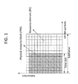
- FIG. 1 illustrates an example structure of a Long Term Evolution/Long Term Evolution Advanced (LTE/LTE-A) subframe.
- LTE/LTE-A Long Term Evolution/Long Term Evolution Advanced
- FIG. 1 the structure of an LTE/LTE-A subframe is shown in time and frequency domain.
- Each subframe is divided into two time slots, with each time slot containing 7 orthogonal frequency-division multiplexing (OFDM) symbols (for normal cyclic prefix length).
- OFDM orthogonal frequency-division multiplexing
- Each grid with an OFDM symbol length and a subcarrier bandwidth is called an RE.
- a PRB has the same length as a time slot in time domain and spans 12 subcarriers in frequency domain.
- the LTE-A network is a heterogeneous network, where macro and pico BSs coexist which may improve spectral efficiency per unit area.
- macro and pico BSs coexist which may improve spectral efficiency per unit area.
- the pico UEs especially those in the cell edge, tend to suffer strong interference from their neighboring macro BSs.
- aspects of the example embodiments may include a pico BS, that involves a central processing unit (CPU) configured to generate interference distribution information for UE scheduling based on at least one power allocation pattern of a plurality of PRBs associated with at least one macro BS; and/or to schedule at least one UE associated with the pico BS based on the interference distribution information.
- CPU central processing unit
- Additional aspects of the example embodiments may include a macro BS, that involves a CPU configured to determine a power allocation pattern for a plurality of PRBs managed by the macro BS, based on the traffic load of at least one victim pico UE; and/or an interface configured to transmit the power allocation pattern to at least one pico BS associated with the at least one victim UE.
- Additional aspects of the example embodiments may include a system, that involves at least one pico BS configured to generate interference distribution information for UE scheduling based on at least one power allocation pattern of a plurality of PRBs associated with at least one macro BS; and/or to schedule at least one UE associated with the at least one pico BS based on the interference distribution information; and/or the at least one macro BS configured to determine the at least one power allocation pattern for the plurality of PRBs managed by the at least one macro BS, based on the traffic load of at least one victim pico UE; and transmit the power allocation pattern to the at least one pico BS associated with the at least one victim UE.
- FIG. 1 illustrates an example structure of an LTE/LTE-A subframe.
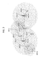
- FIG. 2 illustrates a heterogeneous network, in accordance with an example embodiment.
- FIG. 3 illustrates a block diagram of a hardware configuration of a macro BS, in accordance with an example embodiment.
- FIG. 4 illustrates a block diagram of a hardware configuration of a pico BS, in accordance with an example embodiment.
- FIG. 5 illustrates a block diagram of a hardware configuration of a UE in a LTE-A system.
- FIG. 6 illustrates a flow diagram of a system in accordance with an example embodiment.
- FIG. 7 illustrates a flow diagram for a pico BS to report its traffic load information to its neighboring macro BSs, in accordance with an example embodiment.
- FIG. 8 illustrates a flow diagram for a macro BS, in accordance with an example embodiment.
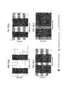
- FIGS. 9(a) to 9(d) illustrate examples of the power allocation pattern, in accordance with an exemplary embodiment.
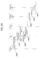
- FIG. 10 illustrates a flowchart of the operations for a pico BS after receiving the power allocation pattern from its neighboring macro BSs, in accordance with an exemplary embodiment.
- a power control scheme is proposed for the macro BSs to reduce their interference to pico UEs in LTE-A heterogeneous networks.
- a pico BS chooses a set of macro BSs to report the traffic load of their victim UEs.
- a macro BS determines its power allocation over the PRBs and shares the power allocation pattern with its neighboring pico BSs.
- the pico BS schedules its associated UEs for data transmission based on the received power allocation patterns from one or more macro BSs.
- the pico UEs For the downlink of a LTE-A heterogeneous network, the pico UEs (e.g., the UEs that are associated with pico cells) suffer strong interference from its neighboring macro BSs due to the high transmit power of the macro BSs.
- a power control scheme is needed for the macro BSs to control their interference to the pico UEs.
- Example embodiments are directed to a power control scheme to reduce the interference between macro BSs and pico UEs, which may improve the cell average and cell edge throughput of the pico UEs.
- a pico BS chooses a set of macro BSs to which the pico BS reports the traffic load of the victim UEs. Based on the traffic load information from one or more pico BSs, a macro BS determines its power allocation over the physical resource blocks (PRBs) and shares the power allocation pattern with its neighboring pico BSs. The pico BS schedules its associated UEs for data transmission based on the received power allocation pattern(s) from one or more macro BSs.
- PRBs physical resource blocks
- FIG. 2 illustrates a heterogeneous network, in accordance with an example embodiment.
- the example heterogeneous cellular network depicted in FIG. 2 there is a mix of pico BSs 200-1, 200-2, macro BSs 201-1, 201-2, and UEs 202-1, 202-2, 202-3, 202-4, 202-5.
- the macro and pico BSs work together to serve multiple UEs in an area.
- the UEs on the cell edge that are associated with the pico BSs may suffer strong interference from the macro BSs.
- UE1 202-1 is associated with pico BS1 200-1, but may suffer strong interference from macro BS1 201-1 and macro BS2 201-2;
- UE3 202-3 is associated with pico BS2 200-2, but may suffer strong interference from macro BS1 201-1.
- the example embodiments can be implemented for the macro and pico BSs such that the interference from the macro BSs to the pico UEs may be reduced.
- FIG. 3 illustrates a block diagram of a hardware configuration of a macro BS, in accordance with an example embodiment.
- the hardware configuration as depicted in the block diagram may be implemented in any macro BS (e.g., such as macro BS1 201-1 and macro BS2 201-2 as depicted in FIG. 2 ).
- the macro BS may use a configuration 300 including an X2 interface 301, a central processing unit (CPU) 302, a radio frequency (RF) module 303, a baseband processor 304 and a memory 305.
- the CPU 302 is configured to determine the power allocation over PRBs based on the input from the X2 interface 301 and updates the power allocation table in the memory 305. Further, the CPU 302 may also be configured to schedule the macro UEs for data transmission and to control the baseband processor 304 and RF module 303, such that the output signal of the RF module follows the selected power allocation pattern.
- the baseband processor 304 is configured to handle baseband operations for the macro BS.
- the baseband operations may include Turbo encoding, rate matching, modulation, layer mapping, MIMO precoding, IFFT, and other operations utilized in the LTE/LTE-A standard.
- the RF module 303 is configured to handle RF operations for the macro BS.
- the RF module converts the baseband signal fed from the baseband processor to RF signal and then transmits the RF signal through one or more antennas.
- the memory 305 is configured to store the power allocation table. Further details about the contents of the power allocation table are provided below in the explanation of Table II.
- the X2 interface 301 is configured to handle information exchange with its neighboring pico BSs. Specifically, the macro BS receives the traffic load information via X2 interface from its neighboring pico BSs. Based on the received information, the macro BS determines its power allocation and informs its neighboring pico BSs of the power allocation pattern via X2 interface. The details of the above procedure are explained in the description for FIG. 8 .
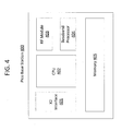
- FIG. 4 illustrates a block diagram of a hardware configuration of a pico BS, in accordance with an example embodiment.
- the hardware configuration as depicted in the block diagram may be implemented in any pico BS (e.g., such as pico BS1 200-1 and pico BS2 200-2 as depicted in FIG. 2 ).
- the pico BS may use a configuration 400 including an X2 interface 401, a central processing unit (CPU) 402, a radio frequency (RF) module 403, a baseband processor 404 and a memory 405.
- the CPU 402 is configured to estimate the interference level for each PRB based on the received power allocation pattern(s) from one or more macro BSs and to update the interference distribution table in the memory 405. Further, the CPU 402 is configured to schedule the pico UEs based on the interference distribution table in the memory 405.
- the CPU 402 also controls the baseband processor 404 and the RF module 403 to transmit data for the scheduled UEs.
- the baseband processor 404 is configured to handle baseband operations for the pico BS.
- the baseband operations for the pico BS are similar to those for the macro BS.
- the RF module 403 is configured to handle RF operations for the pico BS.
- the RF operations for the pico BS are similar to those for the macro BS.
- the memory 405 is configured to store the interference distribution table, details of which are provided below in the description for Table III.
- the X2 interference 401 is configured to handle information exchange with its neighboring pico BSs. Specifically, the pico BS sends its traffic load information via X2 interface to its neighboring macro BSs such that they can determine their power allocation patterns, as described in further detail in the description for FIG. 7 . After receiving the power allocation pattern from its neighboring macro BSs, the pico BS estimates the interference distribution and adjusts its scheduler accordingly, as described in further detail in the description for FIG. 10 .
- FIG. 5 illustrates a block diagram of a hardware configuration of a UE in an LTE-A system.
- the hardware configuration as depicted in the block diagram may be implemented in any UE (e.g., UEs 202-1, 202-2, 202-3, 202-4, 202-5 as depicted in FIG. 2 ) in a LTE-A system.
- the UE may use a configuration 500 including a measurement module 501, a radio frequency (RF) module 502, a baseband processor 503 and a memory 504.
- the measurement module 501 is configured to measure the reference signal received power (RSRP) from its neighboring macro and pico BSs and to send the measurement result to the associated BSs.
- the baseband processor 503 is configured to handle baseband operations for the UE.
- the RF module 502 is configured to handle RF operations for the UE.
- the memory 504 stores received data packets.
- FIG. 6 illustrates a flow diagram of a system in accordance with an example embodiment.
- each UE measures the RSRPs from its neighboring BSs and sends the measurement report to its associated BS.
- each pico BS identifies the victim UEs for each macro BS in the neighborhood, and determines a set of the macro BSs, to which at 602 the pico BS reports the traffic load of their victim UEs.
- the pico BS sends the traffic load information to each macro BS within the reporting set through an X2 interface.
- the traffic load information for the victim UEs may include the number of PRBs assigned to the victim UEs, the packet arrival rate, or the throughput.
- a macro BS determines the power allocation pattern.
- the macro BS shares the pattern with one or more pico BSs (via an X2 interface) for the UE scheduling. Meanwhile, the macro BS may schedule its own UEs for data transmission based on its power allocation pattern.
- the pico BSs generate a data transmission schedule for the associated UEs based on the received power allocation pattern.
- the pico BSs instruct the associated UEs to transmit data packets based on the data transmission schedule.
- FIG. 7 illustrates a flow diagram for a pico BS to report its traffic load information to its neighboring macro BSs, in accordance with an example embodiment.
- the pico BS receives the measurement reports from its associated UEs. References are made with respect to the example hardware configuration 400 of FIG. 4 .
- the CPU receives measurement reports from the associated UEs. Based on the received measurement reports, the CPU updates the RSRP measurement table in the memory 405 as shown at 701 and 702.
- the CPU 402 can identify the victim UEs for a particular macro BS. If the number of victim UEs for a macro BS is above a threshold, the CPU 402 may include the macro BS into the reporting set to report traffic load at 703. At 704, the IDs of the macro BSs in the reporting set are sent to the X2 interface 401 to establish connections with those macro BSs. The X2 interface 401 establishes links to the macro BSs in the reporting set at 705, and requests X2 connections at 706. Once the connection to a macro BS is established, the pico BS will send the traffic load report, which provides the overall traffic load for the victim UEs of this macro BS. For example, pico BS1 200-1 in FIG. 2 will report the sum traffic load of UE1 202-1 and UE2 202-2 to macro BS1 201-1.
- Table I is an example RSRP measurement table for a pico BS (in this example, pico BS1 200-1 as depicted in FIG. 2 ), where the example RSRP values are given for illustration purposes and the example threshold for the victim UE is set to be 10.
- Table I Example RSRP measurement table UE ID Cell ID RSRP Victim UE (Yes/No) UE1 Macro BS1 15 Yes Macro BS2 14 Yes UE2 Macro BS1 17 Yes Macro BS2 6 No
- FIG. 8 illustrates a flow diagram for a macro BS, in accordance with an example embodiment.
- the macro BS receives the traffic load information from one or more pico BSs via an X2 interface 301.
- the CPU 302 determines the power allocation pattern and updates the power allocation table in the memory 305 accordingly, as shown at 801 and 802.
- the CPU sends the power allocation pattern to the RF module such that the output signal of the RF module follows the pattern.
- the power allocation pattern may also be sent to one or more pico BSs as shown at 803.
- the CPU 302 schedules the UEs associated with the macro BS, as shown at 804.
- the PRB indices assigned to each scheduled UE are then sent to the baseband processor 304 for baseband processing as shown at 805 and 806, respectively. Afterwards, the baseband signal is sent to the RF module 303 for RF processing, as shown at 807 and 808, respectively.
- FIGS. 9(a) to 9(d) illustrate examples of the power allocation pattern in time and frequency domain, in accordance with an exemplary embodiment.
- the examples of FIG. 9(a) to 9(d) are for a LTE-A frame, with ten subframes and 1.4MHz bandwidth, and indicate the transmit power for a given PRB and subframe.
- the columns of the examples indicate the subframe index, or the corresponding subframe in the time domain.
- the rows of the examples indicate the PRB index, or the transmit power of a corresponding PRB.
- the power allocation pattern has various structures.
- the transmit power for each PRB can be configured with three values: a first transmit power that is used as a default setting, a second transmit power that is less than the first transmit power (e.g., a certain percentage of the first transmit power), and zero or no transmit power.
- the PRBs within the same subframe may be configured with the first transmit power.
- the PRBs within the same row may be configured with the second transmit power.
- the PRBs within the same row may be configured with no transmit power.
- Multiple power allocation patterns may be predefined and stored in a table in the memory.
- Table II illustrates an example of such a table based on the four power allocation patterns as shown in FIGS. 9(a) to 9(d) , where two bit maps are used to describe the power allocation pattern.
- the power allocation pattern index 1, 2, 3, and 4 correspond to FIG. 9(a), 9(b), 9(c), and 9(d) , respectively.
- the first bit map has ten bits which indicate the locations (subframe) of the PRBs configured with first transmit power
- the send bit map indicates the locations (frequency bands) of the PRBs configured with second transmit power.
- the length of the second bit map may vary.
- the two bit maps for FIG. 9(b) are given as follows.
- First bit map 0 1 1 0 0 1 1 1 0 0, where "1" denotes that the PRBs in the corresponding subframes (columns) are configured with the first transmit power.
- Second bit map 0 1 0 1 0 1, where "1" denotes that the PRBs in the corresponding frequency band (rows) are configured with the second transmit power.
- a unique muting ratio is associated with each power allocation pattern, which is defined as p z +(1 - ⁇ ) p r where p r and p z are the percentages of the PRBs with the second transmit power and no transmit power, respectively and ⁇ is the ratio between the value of the second transmit power and that of the first transmit power.
- Table II Example power allocation table Power allocation pattern index First bit map Second bit map ⁇ Muting ratio Active 1 0 1 1 0 0 0 1 1 0 0 0 0 1 1 0 0 0 0 0 0 0 60% No 2 0 1 1 0 0 1 1 1 0 0 0 1 0 1 0 1 25% 44% Yes 3 0 1 1 1 0 1 1 1 0 0 0 1 0 1 0 1 50% 30% No 4 0 1 1 1 0 1 1 1 1 1 1 1 1 1 1 1 1 1 50% 10% No
- the power allocation pattern is chosen from the power allocation table based on the received traffic load information from one or more pico BSs.
- the CPU of the macro BS then chooses the power allocation pattern whose muting ratio is closest to the above metric and updates the power allocation table by setting the field "Active" of the selected pattern to be “Yes” (the fields "Active” of the rest patterns are set to be “No” automatically) in the memory.
- the CPU of the macro BS schedules its associated UEs for data transmission based on the selected power allocation pattern as follows.
- the UEs are divided into two groups based on their RSRPs: the cell-center UEs whose RSRPs are above a predefined threshold, and the cell-edge UEs whose RSRPs are below the predefined threshold.
- the CPU of the macro BS schedules the cell-center UEs only over the PRBs with second transmit power. For the PRBs with first transmit power, the CPU of the macro BS schedules the UEs from the two groups.
- the PRB indices assigned to each scheduled UE and the active power allocation pattern are passed to the baseband processor and the RF module such that the output signal from the RF module follows the selected power allocation pattern.
- the two bit maps and the value of the second transmit power for the selected power allocation pattern are sent to one or more pico BSs that have X2 connections with the macro BS.
- FIG. 10 illustrates a flowchart of the operations for a pico BS after receiving the power allocation pattern from its neighboring macro BSs, in accordance with an exemplary embodiment.
- the flowchart as illustrated in FIG. 10 is for receiving and processing the power allocation patterns from one or more macro BSs.
- the X2 interface 401 receives the power allocation patterns from one or more macro BSs and forwards them to the CPU 402, as shown at 1000.
- the CPU 402 updates the interference distribution table in the memory 405 based on the received power allocation patterns as shown at 1001 and 1002.
- An example of the interference distribution table is given in Table III (below), where "High” and “Low” denote the interference level for a state that includes a given PRB and a given subframe.
- the details of the updating the interference level for a particular state is as follows.
- the interference level of the state is set to be "High” if the received power allocation pattern indicates that the state is configured with first transmit power or with a second transmit power above a certain threshold. Otherwise, the interference level is set to be "Low”. For example, if the power allocation pattern as shown in FIG. 9(a) is received, the interference table should be updated as shown in Table III.
- the interference level of the PRB is set to be "High” if any of the received power allocation patterns indicate that the PRB is configured with first transmit power or with second transmit power above a certain threshold, then the interference level is set to be "High”. Otherwise, the interference is set to be "Low”. For example, if power allocation patterns as shown in FIG. 9(a) and 9(b) are received and the value of the second transmit power in the pattern of FIG. 9(b) is above the predefined threshold, the interference table should be updated as shown in Table IV.
- the CPU schedules UEs for data transmission based on the interference distribution table as follows.
- the UEs are divided into two groups based on their RSRPs: the cell-center UEs whose RSRPs are above a threshold (e.g., predefined), and the cell-edge UEs whose RSRPs are below the threshold.
- the CPU schedules the cell-edge UEs only over the PRBs with low interference level.
- the CPU schedules the UEs from the two groups.
- the PRB indices assigned to each scheduled UE are passed to baseband processor for the baseband processing as shown in 1004 and 1005.
- the baseband signal of the baseband processing is sent to the RF module 403 for RF processing, as shown at 1006 and 1007.
- the example embodiments also relate to an apparatus for performing the operations herein.
- This apparatus may be specially constructed for the required purposes, or it may include one or more general-purpose computers selectively activated or reconfigured by one or more computer programs.
- Such computer programs may be stored in a computer-readable storage medium, such as, but not limited to optical disks, magnetic disks, read-only memories, random access memories, solid state devices and drives, or any other types of tangible media suitable for storing electronic information.
- the algorithms and displays presented herein are not inherently related to any particular computer or other apparatus.
- the operations described above can be performed by hardware, software, or some combination of software and hardware.
- Various aspects of embodiments of the invention may be implemented using circuits and logic devices (hardware), while other aspects may be implemented using instructions stored on a machine-readable medium (software), which if executed by a processor, would cause the processor to perform a method to carry out the example embodiments.
- some example embodiments may be performed solely in hardware, whereas other example embodiments may be performed solely in software.
- the various functions described can be performed in a single unit, or can be spread across a number of components in any number of ways.
- the methods may be executed by a processor, such as a general purpose computer, based on instructions stored on a computer-readable medium. If desired, the instructions can be stored on the medium in a compressed and/or encrypted format.
Applications Claiming Priority (1)
| Application Number | Priority Date | Filing Date | Title |
|---|---|---|---|
| US13/532,401 US9066303B2 (en) | 2012-06-25 | 2012-06-25 | Power control in LTE-advanced heterogeneous networks |
Publications (2)
| Publication Number | Publication Date |
|---|---|
| EP2680647A2 true EP2680647A2 (fr) | 2014-01-01 |
| EP2680647A3 EP2680647A3 (fr) | 2014-09-17 |
Family
ID=48692307
Family Applications (1)
| Application Number | Title | Priority Date | Filing Date |
|---|---|---|---|
| EP13173477.4A Withdrawn EP2680647A3 (fr) | 2012-06-25 | 2013-06-25 | Commande de puissance dans des réseaux hétérogènes LTE avancés |
Country Status (4)
| Country | Link |
|---|---|
| US (1) | US9066303B2 (fr) |
| EP (1) | EP2680647A3 (fr) |
| JP (1) | JP2014007745A (fr) |
| CN (1) | CN103517436A (fr) |
Cited By (2)
| Publication number | Priority date | Publication date | Assignee | Title |
|---|---|---|---|---|
| CN104488333A (zh) * | 2014-03-20 | 2015-04-01 | 华为终端有限公司 | 发送信号的方法、用户设备和基站 |
| WO2015149858A1 (fr) * | 2014-04-03 | 2015-10-08 | Nokia Solutions And Networks Oy | Échange d'informations de charge pour la coordination du brouillage |
Families Citing this family (29)
| Publication number | Priority date | Publication date | Assignee | Title |
|---|---|---|---|---|
| US9075566B2 (en) | 2012-03-02 | 2015-07-07 | Microsoft Technoogy Licensing, LLC | Flexible hinge spine |
| US9460029B2 (en) | 2012-03-02 | 2016-10-04 | Microsoft Technology Licensing, Llc | Pressure sensitive keys |
| US20130300590A1 (en) | 2012-05-14 | 2013-11-14 | Paul Henry Dietz | Audio Feedback |
| US9351190B2 (en) | 2012-10-15 | 2016-05-24 | Headwater Partners LLC | Interference characterization based on scheduling a transmission mode |
| US9332455B2 (en) * | 2012-10-15 | 2016-05-03 | Headwater Partners Ii Llc | Scheduling a user equipment transmission mode to assist uplink interference characterization |
| US9413502B2 (en) | 2012-10-15 | 2016-08-09 | Headwater Partners LLC | Backhaul assisted by user equipment |
| US9350515B2 (en) | 2012-10-15 | 2016-05-24 | Headwater Partners LLC | Enhanced relay node with additional backhaul alternative and selection |
| US9319916B2 (en) | 2013-03-15 | 2016-04-19 | Isco International, Llc | Method and appartus for signal interference processing |
| US9723616B2 (en) * | 2013-07-10 | 2017-08-01 | Telefonaktiebolaget Lm Ericsson (Publ) | Predictable scheduler for interference mitigation |
| ES2728927T3 (es) | 2014-01-29 | 2019-10-29 | Interdigital Patent Holdings Inc | Selección de recurso para descubrimiento o comunicación de dispositivo a dispositivo |
| US9585103B2 (en) * | 2014-01-30 | 2017-02-28 | Qualcomm Incorporated | Techniques for controlling transmission power in shared radio frequency spectrum |
| US9526110B2 (en) * | 2014-02-20 | 2016-12-20 | Nokia Solutions And Networks Oy | Techniques for multi-RAT (radio access technology) coordinated resource sharing |
| CN110769496B (zh) | 2014-03-19 | 2022-07-08 | 交互数字专利控股公司 | Wtru及由wtru执行的方法 |
| US9794888B2 (en) | 2014-05-05 | 2017-10-17 | Isco International, Llc | Method and apparatus for increasing performance of a communication link of a communication node |
| EP3146752A1 (fr) * | 2014-05-23 | 2017-03-29 | Nokia Solutions and Networks Oy | Partage de bande de fréquence entre cellules |
| US10324733B2 (en) | 2014-07-30 | 2019-06-18 | Microsoft Technology Licensing, Llc | Shutdown notifications |
| US10254942B2 (en) | 2014-07-31 | 2019-04-09 | Microsoft Technology Licensing, Llc | Adaptive sizing and positioning of application windows |
| US10678412B2 (en) | 2014-07-31 | 2020-06-09 | Microsoft Technology Licensing, Llc | Dynamic joint dividers for application windows |
| US9787576B2 (en) | 2014-07-31 | 2017-10-10 | Microsoft Technology Licensing, Llc | Propagating routing awareness for autonomous networks |
| US10592080B2 (en) | 2014-07-31 | 2020-03-17 | Microsoft Technology Licensing, Llc | Assisted presentation of application windows |
| US9414417B2 (en) | 2014-08-07 | 2016-08-09 | Microsoft Technology Licensing, Llc | Propagating communication awareness over a cellular network |
| EP3651386B1 (fr) | 2015-05-04 | 2023-08-23 | ISCO International, LLC | Procédé et appareil pour augmenter la performance de voies de communication pour noeuds de communication |
| US9692468B2 (en) | 2015-11-11 | 2017-06-27 | Smartsky Networks, Llc | Spectrum scrubber |
| CA3024175A1 (fr) | 2016-06-01 | 2017-12-07 | Isco International, Llc | Procede et appareil aptes a executer un conditionnement de signal afin d'attenuer une interference detectee dans un systeme de communication |
| CN116709271A (zh) * | 2017-03-24 | 2023-09-05 | 苹果公司 | 用于机器类型通信和窄带物联网设备的唤醒信号 |
| US10298279B2 (en) | 2017-04-05 | 2019-05-21 | Isco International, Llc | Method and apparatus for increasing performance of communication paths for communication nodes |
| US10284313B2 (en) | 2017-08-09 | 2019-05-07 | Isco International, Llc | Method and apparatus for monitoring, detecting, testing, diagnosing and/or mitigating interference in a communication system |
| CN110475259A (zh) * | 2018-05-10 | 2019-11-19 | 索尼公司 | 频谱管理装置和方法、无线网络管理装置和方法以及介质 |
| CN114071683B (zh) * | 2021-11-04 | 2023-04-14 | 中国联合网络通信集团有限公司 | 一种数据传输方法、装置和电子设备 |
Family Cites Families (22)
| Publication number | Priority date | Publication date | Assignee | Title |
|---|---|---|---|---|
| US8737229B2 (en) * | 2008-07-11 | 2014-05-27 | Qualcomm Incorporated | Access mechanisms for base stations in heterogeneous access point networks |
| CN101742550B (zh) * | 2008-11-06 | 2012-08-22 | 华为技术有限公司 | 确定影响邻小区的用户的方法、相关设备及系统 |
| WO2010106556A2 (fr) * | 2009-03-20 | 2010-09-23 | Centre Of Excellence In Wireless | Gestion des interférences cognitives dans les réseaux sans fil comprenant des relais, des macro-cellules, des micro-cellules, des pico-cellules et des femto-cellules |
| KR101707870B1 (ko) * | 2009-12-15 | 2017-02-17 | 엘지전자 주식회사 | 이종(heterogeneous) 셀 간에 간섭을 제거하기 위한 방법 및 장치 |
| KR20110119551A (ko) * | 2010-04-26 | 2011-11-02 | 삼성전자주식회사 | Ofdm 방식의 계층 셀 시스템에서 제어 채널의 셀 간 간섭 제어 방법 및 이를 위한 장치 |
| CN102256367A (zh) * | 2010-05-20 | 2011-11-23 | 普天信息技术研究院有限公司 | 降低小区间干扰的调度方法及装置 |
| CN102256365B (zh) * | 2010-05-20 | 2014-11-05 | 普天信息技术研究院有限公司 | 降低小区间干扰的方法及装置 |
| WO2012047144A1 (fr) * | 2010-10-04 | 2012-04-12 | Telefonaktiebolaget L M Ericsson (Publ) | Acquisition de données de cellule pour améliorer le fonctionnement d'un réseau dans un environnement hétérogène |
| WO2012061224A1 (fr) | 2010-11-05 | 2012-05-10 | Interdigital Patent Holdings, Inc. | Procédés, appareil et systèmes d'application de motifs de sous-trame presque vide (abs) |
| KR20120071654A (ko) * | 2010-12-23 | 2012-07-03 | 한국전자통신연구원 | 매크로 셀을 고려한 펨토셀 간섭 제어 방법 |
| WO2012096604A1 (fr) * | 2011-01-11 | 2012-07-19 | Telefonaktiebolaget L M Ericsson (Publ) | Procédés pour atténuer les interférences affectant les liaisons montantes dans un groupe fermé d'abonnés non autorisé |
| EP3745636A1 (fr) * | 2011-02-06 | 2020-12-02 | LG Electronics Inc. | Procédé et appareil pour une coordination de brouillage intercellulaire dans un système de communication sans fil |
| CN103444223A (zh) * | 2011-04-04 | 2013-12-11 | 瑞典爱立信有限公司 | 限制异类无线通信系统中的干扰 |
| WO2012154014A2 (fr) * | 2011-05-12 | 2012-11-15 | 엘지전자 주식회사 | Procédé pour la transmission et la réception de données dans un système d'accès sans fil, et station de base et équipement d'utilisateur correspondants |
| WO2013006193A1 (fr) * | 2011-07-01 | 2013-01-10 | Intel Corporation | Décalage de couche dans des communications entrées multiples, sorties multiples en boucle ouverte |
| WO2013025158A1 (fr) * | 2011-08-12 | 2013-02-21 | Telefonaktiebolaget Lm Ericsson (Publ) | Procédés et nœuds pour coordonner des transmissions sur la liaison montante dans un réseau de communication sans fil |
| US9060377B2 (en) | 2011-11-02 | 2015-06-16 | Hitachi, Ltd. | ABS-based method for inter cell interference coordination in LTE-advanced networks |
| US8971275B2 (en) * | 2011-12-31 | 2015-03-03 | Ofinno Technologies, Llc | Almost blank subframe indication in wireless networks |
| US9408217B2 (en) * | 2012-01-17 | 2016-08-02 | Qualcomm Incorporated | Maximum power reduction for interference control in adjacent channels |
| US8755791B2 (en) * | 2012-05-11 | 2014-06-17 | Blackberry Limited | Method and system for low power downlink transmission in heterogeneous networks |
| US8805394B2 (en) * | 2012-05-17 | 2014-08-12 | Intel Corporation | Systems and methods for interference mitigation in heterogeneous networks |
| US10433159B2 (en) * | 2012-08-03 | 2019-10-01 | Texas Instruments Incorporated | Uplink signaling for cooperative multipoint communication |
-
2012
- 2012-06-25 US US13/532,401 patent/US9066303B2/en not_active Expired - Fee Related
-
2013
- 2013-06-24 JP JP2013131761A patent/JP2014007745A/ja active Pending
- 2013-06-25 EP EP13173477.4A patent/EP2680647A3/fr not_active Withdrawn
- 2013-06-25 CN CN201310255856.9A patent/CN103517436A/zh active Pending
Non-Patent Citations (1)
| Title |
|---|
| None |
Cited By (5)
| Publication number | Priority date | Publication date | Assignee | Title |
|---|---|---|---|---|
| CN104488333A (zh) * | 2014-03-20 | 2015-04-01 | 华为终端有限公司 | 发送信号的方法、用户设备和基站 |
| EP3007503A4 (fr) * | 2014-03-20 | 2016-09-21 | Huawei Device Co Ltd | Procédé d'émission de signal, équipement utilisateur, et station de base |
| US10278185B2 (en) | 2014-03-20 | 2019-04-30 | Huawei Device (Dongguan) Co., Ltd. | Signal sending method, user equipment, and base station |
| WO2015149858A1 (fr) * | 2014-04-03 | 2015-10-08 | Nokia Solutions And Networks Oy | Échange d'informations de charge pour la coordination du brouillage |
| US9883417B2 (en) | 2014-04-03 | 2018-01-30 | Nokia Solutions And Networks Oy | Load information exchange for interference coordination |
Also Published As
| Publication number | Publication date |
|---|---|
| US9066303B2 (en) | 2015-06-23 |
| JP2014007745A (ja) | 2014-01-16 |
| CN103517436A (zh) | 2014-01-15 |
| US20130343291A1 (en) | 2013-12-26 |
| EP2680647A3 (fr) | 2014-09-17 |
Similar Documents
| Publication | Publication Date | Title |
|---|---|---|
| EP2680647A2 (fr) | Commande de puissance dans des réseaux hétérogènes LTE avancés | |
| US9060377B2 (en) | ABS-based method for inter cell interference coordination in LTE-advanced networks | |
| EP3225044B1 (fr) | Procédés et appareil pour activer des services de proximité dans des réseaux mobiles | |
| US10015829B2 (en) | Controlling interference | |
| US10390337B2 (en) | Aperiodic channel state information (CSI) reporting for carrier aggregation | |
| EP2410663A1 (fr) | Procédé, appareil et système de distribution de puissance de liaison descendante | |
| US20160007232A1 (en) | Flexible configuration of uplink and downlink ratio by exchanging information using an x2 interface | |
| US20150163008A1 (en) | Method and apparatus for cell discovery | |
| US9686756B2 (en) | Wireless communication apparatus and wireless communication method | |
| US9755794B2 (en) | Methods and arrangements for handling a scheduling of a narrowband transmission in a cellular network | |
| CN106793047B (zh) | 一种上行功率控制方法及基站 | |
| CN112544101B (zh) | 调度方法、装置、存储介质及通信系统 | |
| US20230216635A1 (en) | Method for transmitting srs for plurality of uplink bands in wireless communication system, and apparatus therefor | |
| EP3203672B1 (fr) | Dispositif et procédé d'agrégation de porteuse basée sur tm9 | |
| KR20160089238A (ko) | 무선 통신 시스템에서 협력 전송을 위한 제어 정보 송신 장치 및 방법 | |
| US11817929B2 (en) | Channel state information measurement method and apparatus and network side device | |
| TWI508608B (zh) | 處理無線通訊系統中波束成形回傳的方法及其通訊裝置 | |
| CN105553527A (zh) | 用于无线通信的装置和方法 | |
| US20140274101A1 (en) | Methods and systems for load balancing and interference coordination in networks | |
| US20160212743A1 (en) | Method, apparatus and system for operating and for generating signaling based on subframe sets | |
| EP2809114A1 (fr) | Procédé et dispositif de détermination de puissance de transmission | |
| CN108112081B (zh) | 通信方法及系统 | |
| US8989761B2 (en) | Scheduling data transmissions in a mobile telecommunication network | |
| CN116868634A (zh) | 用于在基于单dci的多trp操作中对上行链路传输进行功率余量报告的系统及方法 | |
| US20160142983A1 (en) | Power control method, ue and communication system |
Legal Events
| Date | Code | Title | Description |
|---|---|---|---|
| PUAI | Public reference made under article 153(3) epc to a published international application that has entered the european phase |
Free format text: ORIGINAL CODE: 0009012 |
|
| 17P | Request for examination filed |
Effective date: 20130906 |
|
| AK | Designated contracting states |
Kind code of ref document: A2 Designated state(s): AL AT BE BG CH CY CZ DE DK EE ES FI FR GB GR HR HU IE IS IT LI LT LU LV MC MK MT NL NO PL PT RO RS SE SI SK SM TR |
|
| AX | Request for extension of the european patent |
Extension state: BA ME |
|
| PUAL | Search report despatched |
Free format text: ORIGINAL CODE: 0009013 |
|
| AK | Designated contracting states |
Kind code of ref document: A3 Designated state(s): AL AT BE BG CH CY CZ DE DK EE ES FI FR GB GR HR HU IE IS IT LI LT LU LV MC MK MT NL NO PL PT RO RS SE SI SK SM TR |
|
| AX | Request for extension of the european patent |
Extension state: BA ME |
|
| RIC1 | Information provided on ipc code assigned before grant |
Ipc: H04B 17/00 20060101ALN20140812BHEP Ipc: H04W 52/24 20090101AFI20140812BHEP |
|
| STAA | Information on the status of an ep patent application or granted ep patent |
Free format text: STATUS: THE APPLICATION HAS BEEN WITHDRAWN |
|
| 18W | Application withdrawn |
Effective date: 20151016 |