EP2680476A2 - Communications apparatus, system and method with error mitigation - Google Patents
Communications apparatus, system and method with error mitigation Download PDFInfo
- Publication number
- EP2680476A2 EP2680476A2 EP13171555.9A EP13171555A EP2680476A2 EP 2680476 A2 EP2680476 A2 EP 2680476A2 EP 13171555 A EP13171555 A EP 13171555A EP 2680476 A2 EP2680476 A2 EP 2680476A2
- Authority
- EP
- European Patent Office
- Prior art keywords
- network
- communication
- error
- received
- data
- Prior art date
- Legal status (The legal status is an assumption and is not a legal conclusion. Google has not performed a legal analysis and makes no representation as to the accuracy of the status listed.)
- Granted
Links
Images
Classifications
-
- H—ELECTRICITY
- H04—ELECTRIC COMMUNICATION TECHNIQUE
- H04L—TRANSMISSION OF DIGITAL INFORMATION, e.g. TELEGRAPHIC COMMUNICATION
- H04L5/00—Arrangements affording multiple use of the transmission path
- H04L5/003—Arrangements for allocating sub-channels of the transmission path
- H04L5/0058—Allocation criteria
- H04L5/006—Quality of the received signal, e.g. BER, SNR, water filling
-
- H—ELECTRICITY
- H04—ELECTRIC COMMUNICATION TECHNIQUE
- H04L—TRANSMISSION OF DIGITAL INFORMATION, e.g. TELEGRAPHIC COMMUNICATION
- H04L1/00—Arrangements for detecting or preventing errors in the information received
- H04L1/004—Arrangements for detecting or preventing errors in the information received by using forward error control
- H04L1/0056—Systems characterized by the type of code used
- H04L1/0061—Error detection codes
-
- H—ELECTRICITY
- H04—ELECTRIC COMMUNICATION TECHNIQUE
- H04L—TRANSMISSION OF DIGITAL INFORMATION, e.g. TELEGRAPHIC COMMUNICATION
- H04L1/00—Arrangements for detecting or preventing errors in the information received
- H04L1/0078—Avoidance of errors by organising the transmitted data in a format specifically designed to deal with errors, e.g. location
- H04L1/0079—Formats for control data
- H04L1/0082—Formats for control data fields explicitly indicating existence of error in data being transmitted, e.g. so that downstream stations can avoid decoding erroneous packet; relays
-
- H—ELECTRICITY
- H04—ELECTRIC COMMUNICATION TECHNIQUE
- H04L—TRANSMISSION OF DIGITAL INFORMATION, e.g. TELEGRAPHIC COMMUNICATION
- H04L49/00—Packet switching elements
- H04L49/55—Prevention, detection or correction of errors
- H04L49/557—Error correction, e.g. fault recovery or fault tolerance
-
- H—ELECTRICITY
- H04—ELECTRIC COMMUNICATION TECHNIQUE
- H04L—TRANSMISSION OF DIGITAL INFORMATION, e.g. TELEGRAPHIC COMMUNICATION
- H04L5/00—Arrangements affording multiple use of the transmission path
- H04L5/003—Arrangements for allocating sub-channels of the transmission path
- H04L5/0078—Timing of allocation
- H04L5/0085—Timing of allocation when channel conditions change
-
- H—ELECTRICITY
- H04—ELECTRIC COMMUNICATION TECHNIQUE
- H04L—TRANSMISSION OF DIGITAL INFORMATION, e.g. TELEGRAPHIC COMMUNICATION
- H04L1/00—Arrangements for detecting or preventing errors in the information received
- H04L2001/0092—Error control systems characterised by the topology of the transmission link
- H04L2001/0094—Bus
Abstract
Description
- Aspects of various embodiments of the present invention are directed to network communications, such as time-based communications.
- In various communications networks, different nodes of a distributed system exchange data through a centralized component. If one of the nodes develops an error, that error may be communicated over the network. Spreading such an error is generally undesirable, particularly on networks such as automotive networks in which safety type components communicate.
- One type of communication approach that has been used in certain applications includes time-based communications, in which a data stream is segmented into frames for sharing a communication medium. Such data communication is susceptible to a variety of errors. For example, a node on the network may develop an error and communicate erroneous data, may communicate during an incorrect time slot, or communications between nodes may be corrupted (e.g., via electro-magnetic interference (EMI)). When errors are detected on a particular branch, further dissemination of the errors can be prevented. However, if one or more nodes on the branch receive the data before an error therein has been generated (e.g., before data is corrupted), those one or more nodes may accept the data. As a result, these nodes have more up-to-date data compared to other nodes in the system that do not receive or reject the data as erroneous. This creates an inconsistency in the freshness of data available to different nodes. However, for a safety critical system, it is desirable that all nodes have the same information and make their decisions based on the same data.
- These and other matters have presented challenges to data communications for a variety of applications.
- Various example embodiments are directed to communication circuits, their implementation, and methods for communication.
- According to a particular example embodiment, an apparatus includes a wired network including a plurality of network branches each having a common communication link, a plurality of network devices connected to the network branches, a plurality of time-slot communication schedules, respectively stored and accessible by each of the network devices, and a central communication circuit (e.g., a central gateway circuit). The plurality of time-slot communication schedules designate time slots during which each network device is assigned to communicate over one of the plurality of network branches. The central communication circuit includes a central-communication schedule stored and accessible by the central communication circuit, data-coupling circuitry configured and arranged for communicatively coupling data between the central communication circuit and each of the plurality of network devices through respective ones of the plurality of network branches, and data-logic circuitry. The data-logic circuitry receives communications from the plurality of network devices using time slots assigned for each network device in the central-communication schedule, and assesses each received communication from one of the network devices on the branch as being error-indicative or not error-indicative. In response to a received communication on one of the network branches being assessed as being error-indicative, the data-logic circuitry facilitates data corruption on the one of the network branches during a time period corresponding to the received communication. Such data corruption may involve, for example, corrupting a data frame on the one of the network branches, by driving against the one of the network branches.
- Another example embodiment is directed to an apparatus having data-logic circuitry and a driver circuit that drives a wired network link for time-based communications with a plurality of different network devices. At least two of the network devices are connected to the wired network link, with each network device being assigned to communicate during different time slots within a communication cycle. The data-logic circuitry assesses communications received on the wired network link as being error-indicative or not error-indicative, using time slots assigned for the at least two network devices in a communication schedule. The driver circuit is operated to drive the wired network link (from which the erroneous data frame is received) during a time slot in which communications assessed as being error-indicative are received. In some implementations, the apparatus operates as a central node that forwards received communications assessed as being not error-indicative, to at least another one of the plurality of network devices.
- Other embodiments are directed to methods for communicating using time-based communications, with a plurality of different network devices in which at least two are connected to a common wired network link, in which each network device is assigned to communicate during different time slots within a communication cycle. For communications received on the common wired network link using time slots assigned for the at least two network devices in a communication schedule, each received communication is assessed as being error-indicative or not error-indicative. In response to received communications assessed as being error-indicative, the common wired network link is driven during a time slot in which the error-indicative communication is received. In some implementations, communications are forwarded to at least another one of the plurality of network devices, in response to the communications being assessed as being not error-indicative.
- The above discussion/summary is not intended to describe each embodiment or every implementation of the present disclosure. The figures and detailed description that follow also exemplify various embodiments.
- Various example embodiments may be more completely understood in consideration of the following detailed description in connection with the accompanying drawings, in which:
-
FIG. 1 shows an apparatus with one or more devices/nodes therein that operate to mitigate error-indicative communications, in accordance with an example embodiment of the present invention; -
FIG. 2 shows another apparatus with a central component coupled to various network devices on respective network branches, in accordance with another example embodiment of the present invention; and -
FIG. 3 is a flow diagram for mitigating error-indicative communications, in accordance with another example embodiment of the present invention. - While the invention is amenable to various modifications and alternative forms, specifics thereof have been shown by way of example in the drawings and will be described in detail. It should be understood, however, that the intention is not to limit the invention to the particular embodiments described. On the contrary, the intention is to cover all modifications, equivalents, and alternatives falling within the scope of the invention, including aspects defined in the claims. In addition, the term "example" as used throughout this application is only by way of illustration, and not limitation.
- Aspects of the present invention are believed to be applicable to a variety of different types of devices, systems and arrangements involving time-based data communications between different network branches, with some or all of the branches having two or more components communicating thereupon. While the present invention is not necessarily so limited, various aspects of the invention may be appreciated through a discussion of examples using this context.
- Various example embodiments are directed to network communication apparatuses, systems and methods in which communications are assessed for errors at one or more network nodes, and in which further communications are effected to ensure that a communication bearing an error at one of the network nodes is not accepted at another network node. This approach may involve, for example, driving a network branch upon which an error-indicative communication is received during a time slot in which the communication is received, to ensure that other devices on the branch do not process the communication.
- Such approaches are, for instance, amenable for implementation to ensure that communications that are received at a first node in an acceptable (e.g., error-free) condition yet are corrupted during transmission before receipt at a second node are not accepted at any of the nodes. This can be useful, for example, to ensure that nodes are not updated with new data unless all nodes receive the data in an acceptable/error-free type of condition.
- A more particular example embodiment is directed to an apparatus including a central network component that assesses communications received along various network branches from devices connected to the branches. When a communication is assessed to be error-indicative, the central network component does not forward the communication to other branches and also drives the originating branch from which the communication is received to ensure that other network devices on the branch do not accept/process the communication. This approach can be carried out, for example, to ensure that those devices on the originating branch that may receive the communication in an error-free condition do not update, accept and/or process the communication. With respect to automotive applications, this approach can ensure that safety-related communications, such as those involved in communication from a braking system, are distributed consistently to different network components.
- In another more particular embodiment, an apparatus includes a wired network including network branches and network devices of which each device is connected to a common communication link of one of the network branches, and communicates using a time-slot communication schedule that designates time slots during which the network device is assigned to communicate. A central communication circuit includes data-coupling circuitry that communicates data between each of the plurality of network devices through respective ones of the plurality of network branches and via the central communication circuit, in accordance with an assigned communication/data-forwarding schedule. Data-logic circuitry receives communications from each network device using a time slot assigned for the network device. Received communications assessed to be error-free or otherwise not error-indicative are forwarded. Communications assessed as being error-indicative are not forwarded and, further, the network branch from which such communications are received is driven during the time slot in which the data is received to ensure that other network devices on the branch do not use or accept/process the data.
- Various embodiments are directed to time-based communications involving a time division multiple access (TDMA) technique, in which a data forwarding schedule is provided to a central component that uses the schedule to forward frames between one or more network branches coupled to the central component. Frames that do not comply with certain protocols can be confined to an originating branch, and that originating branch is further driven (e.g., as discussed above) to ensure that devices on the originating branch do not process the communications.
- In certain embodiments, suppression of error-based communications as discussed herein is carried out using in-vehicle networks (IVNs), such as for automobiles, trains, airplanes and other vehicles. For instance, various embodiments are directed to implementations involving automotive protocols such as the FlexRay protocol, in which the time frames during which data is communicated are monitored for errors and network branches are further driven during such time frames deemed as having error-indicative data communicated therein. This error-suppressive driving can also be carried out independent from any knowledge of which node is communicating on each time frame.
- In some implementations, one or more embodiments as discussed herein are implemented with FlexRay protocol applications specifically targeting the communication needs of the safety critical in-vehicle networks that use TDMA to exchange data during static segments, via a central component (e.g., a Central Bus Guardian) that monitors incoming frames against different rules. Such rules may include, for example, identifying as erroneous: 1) a data frame that appears from a branch during a time slot when the branch is not supposed to transmit; 2) a data frame that appears from a branch too late within its scheduled time slot such that the frame may cause a slot boundary violation; and 3) a data frame that appears from a branch with incorrect header information or checksum. The central component operates to drive branches from which incoming frames are received during the time slot in which the frames are received when the data therein is determined to be erroneous (e.g., corrupted).
- For general information regarding communications protocols, and for specific information regarding communication protocols that may be implemented in connection with one or more example embodiments, reference may be made to the "FlexRay Communications System Protocol Specification," ver 3.0,; and to the "FlexRay Communications System Preliminary Central Bus Guardian Specification," ver 2.0.9, both available from the FlexRay consortium and fully incorporated herein by reference.
- The various example embodiments as discussed herein are implemented with different systems, on different platforms, and with different environments (e.g., automotive, manufacturing and others) to suit a variety of applications. One such application involves a branch-type active star device TJA1085 available from NXP Semiconductors of Eindhoven, The Netherlands. Accordingly, various embodiments are directed to implementation with such a device in an automotive network.
- Turning now to the figures,
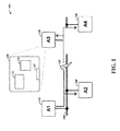
FIG. 1 shows anapparatus 100 with one or more devices/nodes therein that operate to mitigate error-indicative communications, in accordance with another example embodiment of the present invention. Theapparatus 100 includesnetwork devices network device 130, data-coupling circuitry 132 (e.g., a network interface circuit), data-logic circuitry 134 and adriver 136 for driving thecommon network link 150. - Using
network device 130 as an example, when communications are received over thecommon network link 150 viainterface 132, the data-logic circuitry 134 assesses the data to determine whether or not the data is error-indicative. If the data is determined to be error-indicative, the data-logic circuitry 134 operates thedrive circuit 136 to drive thecommon network link 150 during the time frame in which the data is received, which causes other network devices on the link to ignore or otherwise not use data received during the time frame. - For example, when the
network device 110 sends data that reachesnetwork device 120 correctly, that data may be corrupted before reachingnetwork device 130, as represented at 152 (e.g., as interference in the link betweennetwork devices 120 and 130). Accordingly, the data-logic circuit 134 detects the data as being error-indicative, withnetwork device 130 operating in a supervisory type of mode. Based upon the detection, the data-logic circuit 134 operates thedriver 136 to drive thecommon network link 150. As a result, thenetwork device 120 also finds the received data as erroneous, ensuring consistency of freshness in data communicated on the network communication link 150 (e.g., all nodes can base decisions on the same information). For instance, by driving thecommon network link 150 to an undefined state during the time slot in which the data detected as being error-indicative is received, the network devices on the common wired link assess the time slot as being error-indicative and disregard the received data. - As may be implemented as or with the apparatus 100 (or otherwise), another example embodiment is directed to an apparatus having a driver circuit and data-logic circuitry, for use with time-based communications from a plurality of different network devices in which at least two of the network devices are connected to a common wired network link. Each network device is assigned to communicate during different time slots within a communication cycle. The driver circuit configured drives the wired network link at the direction of the data-logic circuitry. In particular, the data-logic circuitry assesses each received communication received on the common wired network link, using the assigned time slots, as being error-indicative or not error-indicative. Communications assessed as being not error-indicative are forwarded to at least another one of the plurality of network devices. For communications assessed as being error-indicative, the driver circuit is operated to drive the common wired network link during a time slot in which the error-indicative communication is received.
- In some implementations, first, second and third such network devices are connected to a common wired link with the second network device being connected between the first and third network device. The third network device includes the driver circuit and data-logic circuitry, and operates to drive against the network link, in response to a communication received from the first network device and delivered error-free to the second network device but assessed as being error-indicative at the third network device. This driving causes the second network device to disregard the error-free communication received at the second network device.
- In other implementations, the driver circuit and data-logic circuitry are in a central communication circuit that operates to forward received data according to a central communication schedule data, to pass data between the network devices for that data assessed as being not error-indicative. For data assessed as being error-indicative, the central communication circuit does not forward the data and also drives against the network branch from which the data is received, which ensures that other devices on the branch disregard the error-indicative data.
- In various implementations, the network devices (e.g., 130) stores a time-slot communication schedule specific to the device. This schedule may, for example, be communicated from a central communication type circuit such as the
circuit 210 as shown inFigure 2 . -
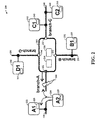
FIG. 2 shows anothercommunication apparatus 200 with a central component coupled to various network devices on respective network branches, in accordance with another example embodiment of the present invention. Theapparatus 200 includes acentral communication circuit 210, and is shown by way of example as having fourbranches branches branch 220 havingdevices branch 240 havingdevices Branches single network devices central communication circuit 210 includes data-coupling circuitry including input/output interface circuits (or ports) 211, 212, 213 and 214 (and, e.g., interconnects within the circuit 210), and a data-logic circuit 216 that forwards data according to both a communication schedule and adriver circuit 218. In some implementations, thecentral communication circuit 210 includes an additional input port designated for receiving configuration data (e.g., from an external source), such as for setting a communication schedule and/or protocol for communicating with the respective network devices. - The data-
logic circuit 216 assesses data received from the respective network branches as being error-indicative or not error-indicative, as may be determined as discussed otherwise herein. Thecentral communication circuit 210 forwards data not indicated as being error-indicative to other branches, according to a communication schedule. For data being error-indicative, thecentral communication circuit 210 selectively does not forward (e.g., blocks) dissemination of the data to other branches, and further drives the branch on which the data has been received during the time slot in which the data was received, therein ensuring other devices on the branch do not use data received during that time slot. - Referring to
network branch 220 by way of example, whennetwork device 224 communicates on the branch, the communication can be received by both thenetwork device 222 and thecentral communication circuit 210. When time slots during whichnetwork device 224 communicates are detected as error indicative at thecentral communication circuit 210, the data-logic circuit 216 controls thedriver circuit 218 to drive thenetwork branch 220 during a time slot detected as having an error. This driving may, for example, drive thenetwork branch 220 to an undefined state. This causes thenetwork device 222 to disregard the communication (e.g., by causing the device to conclude that a checksum or cyclic redundancy check error has occurred during the time slot). This approach can be useful, for example, when a communication fromnetwork device 224 is received in an error-free condition atnetwork device 222, but is corrupted at 260 (shown by way of example) before reaching thecentral communication circuit 210. This can preventnetwork device 222 from updating with the received data which is not received by other devices (e.g., to which the centrallycommunication circuit 210 would have otherwise forwarded the communication) in view of the error. - In this context, the network devices automatically determine that the data received during the time slot should be discarded/disregarded as being in error with respect to receipt of the data on at least another one of the time slots. In some instances, one or more network devices on the branch being driven is responsive to the driving by automatically determining that the data received during the time slot is in error using an error-detecting code and a check value communicated with the received communication (e.g., the driving renders a cyclic redundancy check (CRC) or checksum value to indicate an error). Disregarding received data may include, for example, not storing or using the received data as a processing input (e.g., as may relate to an automatic braking system input), as an update and/or as a configuration input.
- In some embodiments, the
network devices network branch 220. Eachdevice network branch 220 is driven by thecentral communication circuit 210, evaluates received data to be in error. -
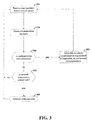
Figure 3 is a flow diagram for mitigating error-indicative communications, in accordance with another example embodiment of the present invention. The diagram shown inFigure 3 is amenable for use with time-based communications from a plurality of different network devices in which two or more of the devices are connected to a common wired network link and each network device is assigned to communicate during different time slots within a communication cycle. This example embodiment is discussed in this context. - At
block 310, communications are received at a network component, via a network link to which two or more devices are connected, using time slots assigned for the network devices. Atblock 320, the received communications are assessed as being error-indicative or not error-indicative. This assessment may involve, for example, assessing for corruption, schedule compliance or other characteristics. - If received communications are not found to be error-indicative at
block 330 and the network component operates as a node that selectively forwards data to other nodes (e.g., as incentral communication circuit 210 inFigure 2 ) atblock 332, the received communications are forwarded to one or more additional network devices atblock 340, and the process continues atblock 310. If the received communications are not found to be error indicative atblock 330 and the network components operates as one of many nodes on a branch (e.g., as incomponent 130 inFigure 1 ), the process continues at block 310 (e.g., with no active forwarding at block 340). If received communications are found to be error-indicative atblock 330, the common wired network link is driven during the time slot in which the error-indicative communication is received atblock 350, the received communications are not forwarded (e.g., if the network component selectively forwards data, such as with central communication circuit 210), and the process continues atblock 310. These approaches are applicable, for example, to a central node receiving data from and forwarding data to network branches, and to nodes on a particular branch that monitor the branch for erroneous data and drive against the branch when such erroneous data is detected. - Accordingly, in some implementations, the approach shown in
Figure 3 is carried out in part at a central communication node connected to respective network branches, in which error-indicative communications are not forwarded to other branches and in which branches from which the error-indicative communications are received are driven to ensure other network devices on the branch do not use/accept/process/update with the data. In other implementations, the approach shown inFigure 3 is carried out at a network device on a network link, by driving the link responsive to detecting error-indicative data in order to ensure that other devices on the link that may have received the data in an error-free state do not use/accept/process/update with the data. - Based upon the above discussion and illustrations, those skilled in the art will readily recognize that various modifications and changes may be made to the present invention without strictly following the exemplary embodiments and applications illustrated and described herein. For example, various types of error detection may be implemented in accordance with embodiments as discussed herein, with time-slot based mitigation of both the dissemination of communications designated as being error-indicative, and the use of such communications as may have been received in an error-free state (e.g., prior to corruption). In addition, one or more components of the various apparatuses and systems described herein may be implemented separately or together, in accordance with one or more example embodiments. Such modifications do not depart from the true spirit and scope of the present invention, including that set forth in the following claims.
Claims (15)
- An apparatus comprising:a wired network including a plurality of network branches each having a common communication link;a plurality of network devices connected to the network branches;a plurality of time-slot communication schedules respectively stored and accessible by each of the network devices, the plurality of time-slot communication schedules designating time slots during which each network device is assigned to communicate over one of the plurality of network branches;a central communication circuit having
a central-communication schedule stored and accessible by the central communication circuit,
data-coupling circuitry configured and arranged for communicatively coupling data between the central communication circuit and each of the plurality of network devices through respective ones of the plurality of network branches, and
data-logic circuitry configured and arranged to
receive communications from the plurality of network devices using time slots assigned for each network device in the central-communication schedule,
assess each received communication from one of the network devices on the branch as being error-indicative or not error-indicative, and
in response to a received communication on one of the network branches being assessed as being error-indicative, facilitate data corruption on the one of the network branches during a time period corresponding to the received communication. - The apparatus of claim 1, wherein the data-logic circuitry is configured and arranged to facilitate data corruption by driving the one of the network branches during a time slot in which the received communication is communicated, thereby corrupting data received by at least one other device on the network branch.
- The apparatus of claim 1 or 2, wherein the data-logic circuitry is configured and arranged to facilitate data corruption by driving the one of the network branches during a time slot in which the received communication is communicated, the network devices on the branch being responsive to the driving of the network branches by automatically determining that the data received during the time slot is in error.
- The apparatus of claim 1, wherein the data-logic circuitry is configured and arranged to facilitate data corruption by driving the one of the network branches during a time slot in which the received communication is communicated, at least one network device on the branch being responsive to the driving of the network branches by automatically determining that the data received during the time slot is in error using an error-detecting code and a check value communicated with the received communication as received at the at least one network device.
- The apparatus of any of the claims 1 to 4, wherein the network devices are configured and arranged to disregard the received communication in response to the data corruption.
- The apparatus of any of the preceding claims, wherein the central communication circuit further includes a driver circuit configured and arranged to drive the network branches for communicating thereupon, and the data-logic circuitry is configured and arranged to facilitate data corruption by controlling the driver circuit to drive network branches in response to the received communication being assessed as error-indicative.
- The apparatus of any of the preceding claims, wherein the data-logic circuitry is configured and arranged to facilitate data corruption by driving the one of the network branches to an undefined state during a time slot in which the received communication is communicated.
- The apparatus of any of the preceding claims, wherein the common communication link in each branch is a common wired-based pathway to which the network devices in each branch are directly connected, said one of the network branches being connected to first and second ones of the network devices, the first one of the network devices being the one of the network devices from which the received communication is assessed as being error-indicative, and the second one of the network devices being configured and arranged to also receive the received communication from the first one of the network devices and being responsive to the data corruption by disregarding the received communication.
- The apparatus of any of the preceding claims, wherein first and second ones of the network devices are directly connected to a common wired-based pathway of said one of the network branches from which said communication assessed as being error-indicative is received, the first and second network devices being assigned to communicate with the central communication circuit during different time slots and each having a microcontroller and a input/output port through which the microcontroller communicates with the common wired-based pathway, said communication assessed as being error-indicative emanating from the first network device and said second network device also receiving said communication from the first network device and being configured and arranged to identify said communication as error-indicative in response to the data corruption.
- An apparatus as claimed in any of the preceding claims, comprising a further apparatus including:a driver circuit configured and arranged to drive the wired network link;data-logic circuitry configured and arranged to
for communications received on the common wired network link using time slots assigned for the at least two network devices in a communication schedule, assess each received communication as being error-indicative or not error-indicative, and
in response to a received communication on the common wired network link being assessed as being error-indicative, operating the driver circuit to drive the common wired network link during a time slot in which the error-indicative communication is received. - The apparatus of claim 10, wherein
the further apparatus is a network device connected to a single branch formed by the common wired network link and to which at least two other network devices are connected to communicate on the branch, and
the data-logic circuitry operates the driver circuit to drive the common wired network link by driving the link to corrupt data sent by one of the at least two other network devices and received by another one of the at least two network devices. - The apparatus of claim 10, wherein
the at least two of the network devices includes first, second and third network devices, the second network device being connected between the first and third network device on the common wired network link, and
the third network device includes the driver circuit and data-logic circuitry and is configured and arranged to
forward, to at least another one of the plurality of network devices, received communications assessed as being not error-indicative, and
for a communication received from the first network device and delivered error-free to the second network device and assessed as being error-indicative at the third network device, operate the driver circuit to drive the common wired network link and cause the second network device to disregard the error-free communication received at the second network device. - For use with time-based communications from a plurality of different network devices, at least two of the network devices connected to a common wired network link in which each network device is assigned to communicate during different time slots within a communication cycle, a method comprising:for communications received on the common wired network link using time slots assigned for the at least two network devices in a communication schedule, assessing each received communication as being error-indicative or not error-indicative; andin response to a received communication on the common wired network link being assessed as being error-indicative, driving the common wired network link during a time slot in which the error-indicative communication is received.
- The method of claim 13, wherein the apparatus is a network device connected to a single branch formed by the common wired network link and to which at least two other network devices are connected to communicate on the branch, and driving the common wired network link includes driving the link to corrupt data sent by one of the at least two other network devices and received by another one of the at least two network devices.
- The method of claims 13 or 14,
wherein the at least two of the network devices includes first, second and third network devices, the second network device being connected between the first and third network device on the common wired network link,
further including, at the third network device, forwarding received communications assessed as being not error-indicative to at least another one of the plurality of network devices, and
wherein the steps of assessing and driving are carried out at the third network device and further include, for a communication received from the first network device and delivered error-free to the second network device and assessed as being error-indicative at the third network device, driving the common wired network link with data that causes the second network device to disregard the error-free communication received at the second network device.
Applications Claiming Priority (1)
| Application Number | Priority Date | Filing Date | Title |
|---|---|---|---|
| US13/535,335 US8817810B2 (en) | 2012-06-27 | 2012-06-27 | Communications apparatus, system and method with error mitigation |
Publications (3)
| Publication Number | Publication Date |
|---|---|
| EP2680476A2 true EP2680476A2 (en) | 2014-01-01 |
| EP2680476A3 EP2680476A3 (en) | 2016-08-10 |
| EP2680476B1 EP2680476B1 (en) | 2017-12-13 |
Family
ID=48626315
Family Applications (1)
| Application Number | Title | Priority Date | Filing Date |
|---|---|---|---|
| EP13171555.9A Active EP2680476B1 (en) | 2012-06-27 | 2013-06-11 | Communications apparatus, system and method with error mitigation |
Country Status (3)
| Country | Link |
|---|---|
| US (2) | US8817810B2 (en) |
| EP (1) | EP2680476B1 (en) |
| CN (1) | CN103516458B (en) |
Cited By (1)
| Publication number | Priority date | Publication date | Assignee | Title |
|---|---|---|---|---|
| EP3340514A1 (en) * | 2016-12-22 | 2018-06-27 | INTEL Corporation | Communication system and methods |
Families Citing this family (4)
| Publication number | Priority date | Publication date | Assignee | Title |
|---|---|---|---|---|
| US8612211B1 (en) | 2012-09-10 | 2013-12-17 | Google Inc. | Speech recognition and summarization |
| EP3098793A1 (en) * | 2015-05-26 | 2016-11-30 | Life Safety Distribution AG | Method for configuring a wireless fire detection system |
| CN109557677A (en) | 2017-09-26 | 2019-04-02 | 歌尔科技有限公司 | Show device and method |
| WO2020090108A1 (en) * | 2018-11-02 | 2020-05-07 | パナソニック インテレクチュアル プロパティ コーポレーション オブ アメリカ | Fraudulent control prevention system and fraudulent control prevention method |
Family Cites Families (11)
| Publication number | Priority date | Publication date | Assignee | Title |
|---|---|---|---|---|
| DE3546664C3 (en) * | 1985-02-22 | 1995-10-26 | Bosch Gmbh Robert | Method for operating a data processing system |
| US5101339A (en) * | 1987-08-10 | 1992-03-31 | Tandon Corporation | Computer address modification system using writable mapping and page stores |
| CA2160499A1 (en) * | 1994-11-30 | 1996-05-31 | Patrick Maurice Bland | Bridge between buses in a system having a plurality of buses with different memory addressing capacities and having an arrangement for reallocating memory segments within the system memory map |
| US5940440A (en) | 1996-05-07 | 1999-08-17 | Lucent Technologies Inc. | Generalized multimodulus technique for blind equalization |
| US5857080A (en) * | 1996-09-10 | 1999-01-05 | Lsi Logic Corporation | Apparatus and method for address translation in bus bridge devices |
| US20020027953A1 (en) | 1997-06-05 | 2002-03-07 | Cheng-I Hwang | Low-complexity blind equalizer |
| KR100565037B1 (en) | 1999-03-27 | 2006-03-30 | 삼성전자주식회사 | Blind Channel Equating Apparatus |
| US6456633B1 (en) * | 1999-04-08 | 2002-09-24 | Avinta Communications, Inc. | Unified distributed voice and data local area networking |
| FI115005B (en) * | 2000-11-20 | 2005-02-15 | Vacon Oyj | Control system for actuators and method for controlling actuators |
| US7245686B2 (en) | 2001-12-17 | 2007-07-17 | Mysticom Ltd. | Fast skew detector |
| US20040022222A1 (en) * | 2002-07-31 | 2004-02-05 | Allister Clisham | Wireless metropolitan area network system and method |
-
2012
- 2012-06-27 US US13/535,335 patent/US8817810B2/en active Active
-
2013
- 2013-06-11 EP EP13171555.9A patent/EP2680476B1/en active Active
- 2013-06-25 CN CN201310255064.1A patent/CN103516458B/en active Active
-
2014
- 2014-07-25 US US14/341,420 patent/US9154285B2/en active Active
Non-Patent Citations (1)
| Title |
|---|
| None |
Cited By (1)
| Publication number | Priority date | Publication date | Assignee | Title |
|---|---|---|---|---|
| EP3340514A1 (en) * | 2016-12-22 | 2018-06-27 | INTEL Corporation | Communication system and methods |
Also Published As
| Publication number | Publication date |
|---|---|
| EP2680476B1 (en) | 2017-12-13 |
| EP2680476A3 (en) | 2016-08-10 |
| US20140003447A1 (en) | 2014-01-02 |
| US9154285B2 (en) | 2015-10-06 |
| CN103516458A (en) | 2014-01-15 |
| US20140334291A1 (en) | 2014-11-13 |
| US8817810B2 (en) | 2014-08-26 |
| CN103516458B (en) | 2016-01-20 |
Similar Documents
| Publication | Publication Date | Title |
|---|---|---|
| US10693905B2 (en) | Invalidity detection electronic control unit, in-vehicle network system, and communication method | |
| US11356475B2 (en) | Frame transmission prevention apparatus, frame transmission prevention method, and in-vehicle network system | |
| US10713106B2 (en) | Communication device, communication method and non-transitory storage medium | |
| US9154285B2 (en) | Communications apparatus, system and method with error mitigation | |
| CN111147437B (en) | Attributing bus disconnect attacks based on erroneous frames | |
| US20150312123A1 (en) | Method and apparatus for isolating a fault in a controller area network | |
| US11843477B2 (en) | Anomaly determination method, anomaly determination device, and recording medium | |
| US20200412756A1 (en) | Communication control device, anomaly detection electronic control unit, mobility network system, communication control method, anomaly detection method, and recording medium | |
| US20170118230A1 (en) | Communication system, control device, and control method | |
| US8122147B2 (en) | Method for acknowledgement of messages in a star network | |
| KR101334017B1 (en) | Apparatus of checking a validity of message on network for a vehicle and method of thereof | |
| EP2680502B1 (en) | Network based on data transmission with time slots | |
| US9499174B2 (en) | Method and apparatus for isolating a fault-active controller in a controller area network | |
| JP2019097088A (en) | Serial communication system | |
| JP6527647B1 (en) | Fraud detection method, fraud detection device and program | |
| KR20130064500A (en) | Method of error recovery while transmitting message in can communication system | |
| US8189497B2 (en) | Error detection and suppression in a TDMA-based network node | |
| US8817811B2 (en) | Communications apparatus, system and method with schedule checking | |
| US20240121036A1 (en) | Network device, communication system and method for the network device | |
| US20230353417A1 (en) | Can module, can transceiver, can system and method for can module | |
| US20240154910A1 (en) | Selective and diverse traffic replication | |
| US10938516B1 (en) | Systems and methods for ethernet packet error detection and correction in automotive environments | |
| JP2020025194A (en) | Information processing apparatus, information processing system, information processing method, and program |
Legal Events
| Date | Code | Title | Description |
|---|---|---|---|
| PUAI | Public reference made under article 153(3) epc to a published international application that has entered the european phase |
Free format text: ORIGINAL CODE: 0009012 |
|
| AK | Designated contracting states |
Kind code of ref document: A2 Designated state(s): AL AT BE BG CH CY CZ DE DK EE ES FI FR GB GR HR HU IE IS IT LI LT LU LV MC MK MT NL NO PL PT RO RS SE SI SK SM TR |
|
| AX | Request for extension of the european patent |
Extension state: BA ME |
|
| 17P | Request for examination filed |
Effective date: 20140326 |
|
| PUAL | Search report despatched |
Free format text: ORIGINAL CODE: 0009013 |
|
| AK | Designated contracting states |
Kind code of ref document: A3 Designated state(s): AL AT BE BG CH CY CZ DE DK EE ES FI FR GB GR HR HU IE IS IT LI LT LU LV MC MK MT NL NO PL PT RO RS SE SI SK SM TR |
|
| AX | Request for extension of the european patent |
Extension state: BA ME |
|
| RIC1 | Information provided on ipc code assigned before grant |
Ipc: H04L 1/00 20060101AFI20160707BHEP Ipc: H04L 5/00 20060101ALN20160707BHEP Ipc: H04L 12/939 20130101ALI20160707BHEP |
|
| RBV | Designated contracting states (corrected) |
Designated state(s): AL AT BE BG CH CY CZ DE DK EE ES FI FR GB GR HR HU IE IS IT LI LT LU LV MC MK MT NL NO PL PT RO RS SE SI SK SM TR |
|
| RIC1 | Information provided on ipc code assigned before grant |
Ipc: H04L 1/00 20060101AFI20170531BHEP Ipc: H04L 5/00 20060101ALN20170531BHEP Ipc: H04L 12/939 20130101ALI20170531BHEP |
|
| GRAP | Despatch of communication of intention to grant a patent |
Free format text: ORIGINAL CODE: EPIDOSNIGR1 |
|
| INTG | Intention to grant announced |
Effective date: 20170710 |
|
| GRAS | Grant fee paid |
Free format text: ORIGINAL CODE: EPIDOSNIGR3 |
|
| GRAA | (expected) grant |
Free format text: ORIGINAL CODE: 0009210 |
|
| AK | Designated contracting states |
Kind code of ref document: B1 Designated state(s): AL AT BE BG CH CY CZ DE DK EE ES FI FR GB GR HR HU IE IS IT LI LT LU LV MC MK MT NL NO PL PT RO RS SE SI SK SM TR |
|
| REG | Reference to a national code |
Ref country code: GB Ref legal event code: FG4D |
|
| REG | Reference to a national code |
Ref country code: AT Ref legal event code: REF Ref document number: 955299 Country of ref document: AT Kind code of ref document: T Effective date: 20171215 Ref country code: CH Ref legal event code: EP |
|
| REG | Reference to a national code |
Ref country code: IE Ref legal event code: FG4D |
|
| REG | Reference to a national code |
Ref country code: DE Ref legal event code: R096 Ref document number: 602013030682 Country of ref document: DE |
|
| REG | Reference to a national code |
Ref country code: NL Ref legal event code: MP Effective date: 20171213 |
|
| REG | Reference to a national code |
Ref country code: LT Ref legal event code: MG4D |
|
| PG25 | Lapsed in a contracting state [announced via postgrant information from national office to epo] |
Ref country code: SE Free format text: LAPSE BECAUSE OF FAILURE TO SUBMIT A TRANSLATION OF THE DESCRIPTION OR TO PAY THE FEE WITHIN THE PRESCRIBED TIME-LIMIT Effective date: 20171213 Ref country code: FI Free format text: LAPSE BECAUSE OF FAILURE TO SUBMIT A TRANSLATION OF THE DESCRIPTION OR TO PAY THE FEE WITHIN THE PRESCRIBED TIME-LIMIT Effective date: 20171213 Ref country code: NO Free format text: LAPSE BECAUSE OF FAILURE TO SUBMIT A TRANSLATION OF THE DESCRIPTION OR TO PAY THE FEE WITHIN THE PRESCRIBED TIME-LIMIT Effective date: 20180313 Ref country code: LT Free format text: LAPSE BECAUSE OF FAILURE TO SUBMIT A TRANSLATION OF THE DESCRIPTION OR TO PAY THE FEE WITHIN THE PRESCRIBED TIME-LIMIT Effective date: 20171213 |
|
| REG | Reference to a national code |
Ref country code: AT Ref legal event code: MK05 Ref document number: 955299 Country of ref document: AT Kind code of ref document: T Effective date: 20171213 |
|
| PG25 | Lapsed in a contracting state [announced via postgrant information from national office to epo] |
Ref country code: BG Free format text: LAPSE BECAUSE OF FAILURE TO SUBMIT A TRANSLATION OF THE DESCRIPTION OR TO PAY THE FEE WITHIN THE PRESCRIBED TIME-LIMIT Effective date: 20180313 Ref country code: GR Free format text: LAPSE BECAUSE OF FAILURE TO SUBMIT A TRANSLATION OF THE DESCRIPTION OR TO PAY THE FEE WITHIN THE PRESCRIBED TIME-LIMIT Effective date: 20180314 Ref country code: RS Free format text: LAPSE BECAUSE OF FAILURE TO SUBMIT A TRANSLATION OF THE DESCRIPTION OR TO PAY THE FEE WITHIN THE PRESCRIBED TIME-LIMIT Effective date: 20171213 Ref country code: LV Free format text: LAPSE BECAUSE OF FAILURE TO SUBMIT A TRANSLATION OF THE DESCRIPTION OR TO PAY THE FEE WITHIN THE PRESCRIBED TIME-LIMIT Effective date: 20171213 Ref country code: HR Free format text: LAPSE BECAUSE OF FAILURE TO SUBMIT A TRANSLATION OF THE DESCRIPTION OR TO PAY THE FEE WITHIN THE PRESCRIBED TIME-LIMIT Effective date: 20171213 |
|
| REG | Reference to a national code |
Ref country code: FR Ref legal event code: PLFP Year of fee payment: 6 |
|
| PG25 | Lapsed in a contracting state [announced via postgrant information from national office to epo] |
Ref country code: NL Free format text: LAPSE BECAUSE OF FAILURE TO SUBMIT A TRANSLATION OF THE DESCRIPTION OR TO PAY THE FEE WITHIN THE PRESCRIBED TIME-LIMIT Effective date: 20171213 |
|
| PG25 | Lapsed in a contracting state [announced via postgrant information from national office to epo] |
Ref country code: ES Free format text: LAPSE BECAUSE OF FAILURE TO SUBMIT A TRANSLATION OF THE DESCRIPTION OR TO PAY THE FEE WITHIN THE PRESCRIBED TIME-LIMIT Effective date: 20171213 Ref country code: CZ Free format text: LAPSE BECAUSE OF FAILURE TO SUBMIT A TRANSLATION OF THE DESCRIPTION OR TO PAY THE FEE WITHIN THE PRESCRIBED TIME-LIMIT Effective date: 20171213 Ref country code: CY Free format text: LAPSE BECAUSE OF FAILURE TO SUBMIT A TRANSLATION OF THE DESCRIPTION OR TO PAY THE FEE WITHIN THE PRESCRIBED TIME-LIMIT Effective date: 20171213 Ref country code: EE Free format text: LAPSE BECAUSE OF FAILURE TO SUBMIT A TRANSLATION OF THE DESCRIPTION OR TO PAY THE FEE WITHIN THE PRESCRIBED TIME-LIMIT Effective date: 20171213 Ref country code: SK Free format text: LAPSE BECAUSE OF FAILURE TO SUBMIT A TRANSLATION OF THE DESCRIPTION OR TO PAY THE FEE WITHIN THE PRESCRIBED TIME-LIMIT Effective date: 20171213 |
|
| PG25 | Lapsed in a contracting state [announced via postgrant information from national office to epo] |
Ref country code: RO Free format text: LAPSE BECAUSE OF FAILURE TO SUBMIT A TRANSLATION OF THE DESCRIPTION OR TO PAY THE FEE WITHIN THE PRESCRIBED TIME-LIMIT Effective date: 20171213 Ref country code: IT Free format text: LAPSE BECAUSE OF FAILURE TO SUBMIT A TRANSLATION OF THE DESCRIPTION OR TO PAY THE FEE WITHIN THE PRESCRIBED TIME-LIMIT Effective date: 20171213 Ref country code: IS Free format text: LAPSE BECAUSE OF FAILURE TO SUBMIT A TRANSLATION OF THE DESCRIPTION OR TO PAY THE FEE WITHIN THE PRESCRIBED TIME-LIMIT Effective date: 20180413 Ref country code: AT Free format text: LAPSE BECAUSE OF FAILURE TO SUBMIT A TRANSLATION OF THE DESCRIPTION OR TO PAY THE FEE WITHIN THE PRESCRIBED TIME-LIMIT Effective date: 20171213 Ref country code: SM Free format text: LAPSE BECAUSE OF FAILURE TO SUBMIT A TRANSLATION OF THE DESCRIPTION OR TO PAY THE FEE WITHIN THE PRESCRIBED TIME-LIMIT Effective date: 20171213 Ref country code: PL Free format text: LAPSE BECAUSE OF FAILURE TO SUBMIT A TRANSLATION OF THE DESCRIPTION OR TO PAY THE FEE WITHIN THE PRESCRIBED TIME-LIMIT Effective date: 20171213 |
|
| REG | Reference to a national code |
Ref country code: DE Ref legal event code: R097 Ref document number: 602013030682 Country of ref document: DE |
|
| PLBE | No opposition filed within time limit |
Free format text: ORIGINAL CODE: 0009261 |
|
| STAA | Information on the status of an ep patent application or granted ep patent |
Free format text: STATUS: NO OPPOSITION FILED WITHIN TIME LIMIT |
|
| 26N | No opposition filed |
Effective date: 20180914 |
|
| PG25 | Lapsed in a contracting state [announced via postgrant information from national office to epo] |
Ref country code: DK Free format text: LAPSE BECAUSE OF FAILURE TO SUBMIT A TRANSLATION OF THE DESCRIPTION OR TO PAY THE FEE WITHIN THE PRESCRIBED TIME-LIMIT Effective date: 20171213 |
|
| REG | Reference to a national code |
Ref country code: CH Ref legal event code: PL |
|
| PG25 | Lapsed in a contracting state [announced via postgrant information from national office to epo] |
Ref country code: SI Free format text: LAPSE BECAUSE OF FAILURE TO SUBMIT A TRANSLATION OF THE DESCRIPTION OR TO PAY THE FEE WITHIN THE PRESCRIBED TIME-LIMIT Effective date: 20171213 |
|
| REG | Reference to a national code |
Ref country code: BE Ref legal event code: MM Effective date: 20180630 |
|
| REG | Reference to a national code |
Ref country code: IE Ref legal event code: MM4A |
|
| PG25 | Lapsed in a contracting state [announced via postgrant information from national office to epo] |
Ref country code: LU Free format text: LAPSE BECAUSE OF NON-PAYMENT OF DUE FEES Effective date: 20180611 Ref country code: MC Free format text: LAPSE BECAUSE OF FAILURE TO SUBMIT A TRANSLATION OF THE DESCRIPTION OR TO PAY THE FEE WITHIN THE PRESCRIBED TIME-LIMIT Effective date: 20171213 |
|
| PG25 | Lapsed in a contracting state [announced via postgrant information from national office to epo] |
Ref country code: IE Free format text: LAPSE BECAUSE OF NON-PAYMENT OF DUE FEES Effective date: 20180611 Ref country code: CH Free format text: LAPSE BECAUSE OF NON-PAYMENT OF DUE FEES Effective date: 20180630 Ref country code: LI Free format text: LAPSE BECAUSE OF NON-PAYMENT OF DUE FEES Effective date: 20180630 |
|
| PG25 | Lapsed in a contracting state [announced via postgrant information from national office to epo] |
Ref country code: BE Free format text: LAPSE BECAUSE OF NON-PAYMENT OF DUE FEES Effective date: 20180630 |
|
| PG25 | Lapsed in a contracting state [announced via postgrant information from national office to epo] |
Ref country code: MT Free format text: LAPSE BECAUSE OF NON-PAYMENT OF DUE FEES Effective date: 20180611 |
|
| PG25 | Lapsed in a contracting state [announced via postgrant information from national office to epo] |
Ref country code: TR Free format text: LAPSE BECAUSE OF FAILURE TO SUBMIT A TRANSLATION OF THE DESCRIPTION OR TO PAY THE FEE WITHIN THE PRESCRIBED TIME-LIMIT Effective date: 20171213 |
|
| PG25 | Lapsed in a contracting state [announced via postgrant information from national office to epo] |
Ref country code: PT Free format text: LAPSE BECAUSE OF FAILURE TO SUBMIT A TRANSLATION OF THE DESCRIPTION OR TO PAY THE FEE WITHIN THE PRESCRIBED TIME-LIMIT Effective date: 20171213 Ref country code: HU Free format text: LAPSE BECAUSE OF FAILURE TO SUBMIT A TRANSLATION OF THE DESCRIPTION OR TO PAY THE FEE WITHIN THE PRESCRIBED TIME-LIMIT; INVALID AB INITIO Effective date: 20130611 |
|
| PG25 | Lapsed in a contracting state [announced via postgrant information from national office to epo] |
Ref country code: MK Free format text: LAPSE BECAUSE OF NON-PAYMENT OF DUE FEES Effective date: 20171213 |
|
| PG25 | Lapsed in a contracting state [announced via postgrant information from national office to epo] |
Ref country code: AL Free format text: LAPSE BECAUSE OF FAILURE TO SUBMIT A TRANSLATION OF THE DESCRIPTION OR TO PAY THE FEE WITHIN THE PRESCRIBED TIME-LIMIT Effective date: 20171213 |
|
| PGFP | Annual fee paid to national office [announced via postgrant information from national office to epo] |
Ref country code: FR Payment date: 20230523 Year of fee payment: 11 Ref country code: DE Payment date: 20230523 Year of fee payment: 11 |
|
| P01 | Opt-out of the competence of the unified patent court (upc) registered |
Effective date: 20230725 |
|
| PGFP | Annual fee paid to national office [announced via postgrant information from national office to epo] |
Ref country code: GB Payment date: 20230524 Year of fee payment: 11 |