EP2680350B1 - Supporter for fuel cell, method of preparing same, and electrode for fuel cell, membrane-electrode assembly for a fuel cell, and fuel cell system including same - Google Patents
Supporter for fuel cell, method of preparing same, and electrode for fuel cell, membrane-electrode assembly for a fuel cell, and fuel cell system including same Download PDFInfo
- Publication number
- EP2680350B1 EP2680350B1 EP12190605.1A EP12190605A EP2680350B1 EP 2680350 B1 EP2680350 B1 EP 2680350B1 EP 12190605 A EP12190605 A EP 12190605A EP 2680350 B1 EP2680350 B1 EP 2680350B1
- Authority
- EP
- European Patent Office
- Prior art keywords
- fuel cell
- carbonaceous material
- supporter
- transition metal
- metal oxide
- Prior art date
- Legal status (The legal status is an assumption and is not a legal conclusion. Google has not performed a legal analysis and makes no representation as to the accuracy of the status listed.)
- Not-in-force
Links
Images





Classifications
-
- H—ELECTRICITY
- H01—ELECTRIC ELEMENTS
- H01M—PROCESSES OR MEANS, e.g. BATTERIES, FOR THE DIRECT CONVERSION OF CHEMICAL ENERGY INTO ELECTRICAL ENERGY
- H01M4/00—Electrodes
- H01M4/86—Inert electrodes with catalytic activity, e.g. for fuel cells
- H01M4/96—Carbon-based electrodes
-
- H—ELECTRICITY
- H01—ELECTRIC ELEMENTS
- H01M—PROCESSES OR MEANS, e.g. BATTERIES, FOR THE DIRECT CONVERSION OF CHEMICAL ENERGY INTO ELECTRICAL ENERGY
- H01M4/00—Electrodes
- H01M4/86—Inert electrodes with catalytic activity, e.g. for fuel cells
- H01M4/90—Selection of catalytic material
- H01M4/92—Metals of platinum group
-
- B—PERFORMING OPERATIONS; TRANSPORTING
- B01—PHYSICAL OR CHEMICAL PROCESSES OR APPARATUS IN GENERAL
- B01J—CHEMICAL OR PHYSICAL PROCESSES, e.g. CATALYSIS OR COLLOID CHEMISTRY; THEIR RELEVANT APPARATUS
- B01J21/00—Catalysts comprising the elements, oxides, or hydroxides of magnesium, boron, aluminium, carbon, silicon, titanium, zirconium, or hafnium
- B01J21/18—Carbon
-
- H—ELECTRICITY
- H01—ELECTRIC ELEMENTS
- H01M—PROCESSES OR MEANS, e.g. BATTERIES, FOR THE DIRECT CONVERSION OF CHEMICAL ENERGY INTO ELECTRICAL ENERGY
- H01M4/00—Electrodes
- H01M4/86—Inert electrodes with catalytic activity, e.g. for fuel cells
-
- H—ELECTRICITY
- H01—ELECTRIC ELEMENTS
- H01M—PROCESSES OR MEANS, e.g. BATTERIES, FOR THE DIRECT CONVERSION OF CHEMICAL ENERGY INTO ELECTRICAL ENERGY
- H01M4/00—Electrodes
- H01M4/86—Inert electrodes with catalytic activity, e.g. for fuel cells
- H01M4/90—Selection of catalytic material
- H01M4/9016—Oxides, hydroxides or oxygenated metallic salts
-
- H—ELECTRICITY
- H01—ELECTRIC ELEMENTS
- H01M—PROCESSES OR MEANS, e.g. BATTERIES, FOR THE DIRECT CONVERSION OF CHEMICAL ENERGY INTO ELECTRICAL ENERGY
- H01M4/00—Electrodes
- H01M4/86—Inert electrodes with catalytic activity, e.g. for fuel cells
- H01M4/90—Selection of catalytic material
- H01M4/9075—Catalytic material supported on carriers, e.g. powder carriers
- H01M4/9083—Catalytic material supported on carriers, e.g. powder carriers on carbon or graphite
-
- H—ELECTRICITY
- H01—ELECTRIC ELEMENTS
- H01M—PROCESSES OR MEANS, e.g. BATTERIES, FOR THE DIRECT CONVERSION OF CHEMICAL ENERGY INTO ELECTRICAL ENERGY
- H01M4/00—Electrodes
- H01M4/86—Inert electrodes with catalytic activity, e.g. for fuel cells
- H01M4/90—Selection of catalytic material
- H01M4/92—Metals of platinum group
- H01M4/921—Alloys or mixtures with metallic elements
-
- H—ELECTRICITY
- H01—ELECTRIC ELEMENTS
- H01M—PROCESSES OR MEANS, e.g. BATTERIES, FOR THE DIRECT CONVERSION OF CHEMICAL ENERGY INTO ELECTRICAL ENERGY
- H01M4/00—Electrodes
- H01M4/86—Inert electrodes with catalytic activity, e.g. for fuel cells
- H01M4/90—Selection of catalytic material
- H01M4/92—Metals of platinum group
- H01M4/925—Metals of platinum group supported on carriers, e.g. powder carriers
- H01M4/926—Metals of platinum group supported on carriers, e.g. powder carriers on carbon or graphite
-
- H—ELECTRICITY
- H01—ELECTRIC ELEMENTS
- H01M—PROCESSES OR MEANS, e.g. BATTERIES, FOR THE DIRECT CONVERSION OF CHEMICAL ENERGY INTO ELECTRICAL ENERGY
- H01M8/00—Fuel cells; Manufacture thereof
- H01M8/02—Details
-
- H—ELECTRICITY
- H01—ELECTRIC ELEMENTS
- H01M—PROCESSES OR MEANS, e.g. BATTERIES, FOR THE DIRECT CONVERSION OF CHEMICAL ENERGY INTO ELECTRICAL ENERGY
- H01M8/00—Fuel cells; Manufacture thereof
- H01M8/02—Details
- H01M8/0202—Collectors; Separators, e.g. bipolar separators; Interconnectors
- H01M8/023—Porous and characterised by the material
- H01M8/0234—Carbonaceous material
-
- H—ELECTRICITY
- H01—ELECTRIC ELEMENTS
- H01M—PROCESSES OR MEANS, e.g. BATTERIES, FOR THE DIRECT CONVERSION OF CHEMICAL ENERGY INTO ELECTRICAL ENERGY
- H01M8/00—Fuel cells; Manufacture thereof
- H01M8/10—Fuel cells with solid electrolytes
- H01M8/1016—Fuel cells with solid electrolytes characterised by the electrolyte material
- H01M8/1018—Polymeric electrolyte materials
-
- B—PERFORMING OPERATIONS; TRANSPORTING
- B82—NANOTECHNOLOGY
- B82Y—SPECIFIC USES OR APPLICATIONS OF NANOSTRUCTURES; MEASUREMENT OR ANALYSIS OF NANOSTRUCTURES; MANUFACTURE OR TREATMENT OF NANOSTRUCTURES
- B82Y30/00—Nanotechnology for materials or surface science, e.g. nanocomposites
-
- H—ELECTRICITY
- H01—ELECTRIC ELEMENTS
- H01M—PROCESSES OR MEANS, e.g. BATTERIES, FOR THE DIRECT CONVERSION OF CHEMICAL ENERGY INTO ELECTRICAL ENERGY
- H01M4/00—Electrodes
- H01M4/86—Inert electrodes with catalytic activity, e.g. for fuel cells
- H01M4/8647—Inert electrodes with catalytic activity, e.g. for fuel cells consisting of more than one material, e.g. consisting of composites
- H01M4/8657—Inert electrodes with catalytic activity, e.g. for fuel cells consisting of more than one material, e.g. consisting of composites layered
-
- H—ELECTRICITY
- H01—ELECTRIC ELEMENTS
- H01M—PROCESSES OR MEANS, e.g. BATTERIES, FOR THE DIRECT CONVERSION OF CHEMICAL ENERGY INTO ELECTRICAL ENERGY
- H01M4/00—Electrodes
- H01M4/86—Inert electrodes with catalytic activity, e.g. for fuel cells
- H01M4/88—Processes of manufacture
- H01M4/8825—Methods for deposition of the catalytic active composition
- H01M4/8828—Coating with slurry or ink
-
- H—ELECTRICITY
- H01—ELECTRIC ELEMENTS
- H01M—PROCESSES OR MEANS, e.g. BATTERIES, FOR THE DIRECT CONVERSION OF CHEMICAL ENERGY INTO ELECTRICAL ENERGY
- H01M4/00—Electrodes
- H01M4/86—Inert electrodes with catalytic activity, e.g. for fuel cells
- H01M4/88—Processes of manufacture
- H01M4/8825—Methods for deposition of the catalytic active composition
- H01M4/8842—Coating using a catalyst salt precursor in solution followed by evaporation and reduction of the precursor
-
- H—ELECTRICITY
- H01—ELECTRIC ELEMENTS
- H01M—PROCESSES OR MEANS, e.g. BATTERIES, FOR THE DIRECT CONVERSION OF CHEMICAL ENERGY INTO ELECTRICAL ENERGY
- H01M4/00—Electrodes
- H01M4/86—Inert electrodes with catalytic activity, e.g. for fuel cells
- H01M4/90—Selection of catalytic material
- H01M4/92—Metals of platinum group
- H01M4/925—Metals of platinum group supported on carriers, e.g. powder carriers
-
- Y—GENERAL TAGGING OF NEW TECHNOLOGICAL DEVELOPMENTS; GENERAL TAGGING OF CROSS-SECTIONAL TECHNOLOGIES SPANNING OVER SEVERAL SECTIONS OF THE IPC; TECHNICAL SUBJECTS COVERED BY FORMER USPC CROSS-REFERENCE ART COLLECTIONS [XRACs] AND DIGESTS
- Y02—TECHNOLOGIES OR APPLICATIONS FOR MITIGATION OR ADAPTATION AGAINST CLIMATE CHANGE
- Y02E—REDUCTION OF GREENHOUSE GAS [GHG] EMISSIONS, RELATED TO ENERGY GENERATION, TRANSMISSION OR DISTRIBUTION
- Y02E60/00—Enabling technologies; Technologies with a potential or indirect contribution to GHG emissions mitigation
- Y02E60/30—Hydrogen technology
- Y02E60/50—Fuel cells
-
- Y—GENERAL TAGGING OF NEW TECHNOLOGICAL DEVELOPMENTS; GENERAL TAGGING OF CROSS-SECTIONAL TECHNOLOGIES SPANNING OVER SEVERAL SECTIONS OF THE IPC; TECHNICAL SUBJECTS COVERED BY FORMER USPC CROSS-REFERENCE ART COLLECTIONS [XRACs] AND DIGESTS
- Y10—TECHNICAL SUBJECTS COVERED BY FORMER USPC
- Y10S—TECHNICAL SUBJECTS COVERED BY FORMER USPC CROSS-REFERENCE ART COLLECTIONS [XRACs] AND DIGESTS
- Y10S977/00—Nanotechnology
- Y10S977/70—Nanostructure
- Y10S977/773—Nanoparticle, i.e. structure having three dimensions of 100 nm or less
-
- Y—GENERAL TAGGING OF NEW TECHNOLOGICAL DEVELOPMENTS; GENERAL TAGGING OF CROSS-SECTIONAL TECHNOLOGIES SPANNING OVER SEVERAL SECTIONS OF THE IPC; TECHNICAL SUBJECTS COVERED BY FORMER USPC CROSS-REFERENCE ART COLLECTIONS [XRACs] AND DIGESTS
- Y10—TECHNICAL SUBJECTS COVERED BY FORMER USPC
- Y10S—TECHNICAL SUBJECTS COVERED BY FORMER USPC CROSS-REFERENCE ART COLLECTIONS [XRACs] AND DIGESTS
- Y10S977/00—Nanotechnology
- Y10S977/902—Specified use of nanostructure
- Y10S977/932—Specified use of nanostructure for electronic or optoelectronic application
- Y10S977/948—Energy storage/generating using nanostructure, e.g. fuel cell, battery
Definitions
- the disclosure relates to a supporter for a fuel cell and a method of preparing the same, and an electrode, a membrane-electrode assembly, and a fuel cell system including the same.
- a fuel cell is a power generation system for producing electrical energy through a chemical reaction of an oxidant and hydrogen from a hydrocarbon-based material such as methanol, ethanol, or natural gas. Such a fuel cell is a clean energy source with the potential to replace fossil fuels.
- Fuel cells include a stack composed of unit cells, and produce various ranges of power. Since it has four to ten times higher energy density than a small lithium battery, it has been highlighted as a small portable power source.
- Typical examples of fuel cells are polymer electrolyte membrane fuel cells (PEMFC) and direct oxidation fuel cells (DOFC).
- a direct oxidation fuel cell that uses methanol as a fuel is called a direct methanol fuel cell (DMFC).
- the polymer electrolyte fuel cell has an advantage of high energy density and high power, and a direct oxidation fuel cell has lower energy density than that of the polymer electrolyte fuel cell, but it has the advantages of easy handling of a fuel, being capable of operating at room temperature due to its low operation temperature, and no need for additional fuel reforming processors.
- the stack that generates electricity substantially includes several to scores of unit cells stacked adjacent to one another, and each unit cell is formed of a membrane-electrode assembly (MEA) and a separator (also referred to as a bipolar plate).
- MEA membrane-electrode assembly
- the membrane-electrode assembly is composed of an anode (also referred to as a "fuel electrode” or an “oxidation electrode”) and a cathode (also referred to as an "air electrode” or a “reduction electrode”) that are separated by a polymer electrolyte membrane.
- a fuel is supplied to the anode and adsorbed on catalysts of the anode, and the fuel is oxidized to produce protons and electrons.
- EP1883131 discloses a supported catalyst for a fuel cell.
- JP2008-181696 discloses a catalyst for a fuel cell.
- US2011/151354 discloses an electrode catalyst for a fuel cell.
- An embodiment of the present invention provides a supporter for a fuel cell exhibiting good stability as claimed in claim 1.
- Another embodiment of the present invention provides a method of preparing the supporter for a fuel cell as claimed in claim 2.
- Yet another embodiment of the present invention provides an electrode for a fuel cell including the supporter as claimed in claim 7.
- Still another embodiment of the present invention provides a membrane-electrode assembly for a fuel cell including the electrode as claimed in claim 8. Still another embodiment of the present invention provides a fuel cell system including the membrane-electrode assembly as claimed in claim 9.
- a supporter for a fuel cell includes a carbonaceous material and a transition metal oxide coating layer formed on a surface of the carbonaceous material, wherein the surface of the carbonaceous material is covalently bonded with the transition metal oxide and the transition metal oxide has an average particle size of 1.5 nm to 10 nm.
- the carbonaceous material comprises carbon nanotubes, optionally with at least one of graphite, denka black, ketjen black, acetylene black, carbon nanofiber, carbon nanowire, carbon nanoballs, and activated carbon.
- the transition metal oxide is ZrO 2 .
- this may be in combination with SnO 2 , WO 3 , TiO 2 , or InO 2 .
- the transition metal oxide is a composite metal oxide including at least two of Zr, Sn, W, Ti, and In but with the proviso that it comprises ZrO 2 .
- the amount of the transition metal oxide is preferably between 5 wt% to 95 wt% based on 100 wt% of the supporter.
- Another embodiment of the present invention provides the supporter and an active metal supported on the supporter.
- the active metal is preferably at least one selected from platinum, ruthenium, osmium, a platinum/ruthenium alloy, a platinum/osmium alloy, a platinum/palladium alloy, a platinum/M alloy (M is a transition element of Ga, Ti, V, Cr, Mn, Fe, Co, Ni, Cu, Zn, Sn, Mo, W, Rh, Ru, or a combination thereof), or a combination thereof.
- Still another embodiment provides a membrane-electrode assembly for a fuel cell comprising the electrode as at least one of a cathode and an anode.
- the embodiment may relate to a membrane-electrode assembly including an anode and a cathode facing each other, and a polymer electrolyte membrane interposed between the cathode and the anode, wherein at least one of the cathode and the anode is the electrode.
- a fuel cell system that includes at least one electricity generating element including the membrane-electrode assembly and separators positioned at each side of the membrane-electrode assembly, a fuel supplier, and an oxidant supplier.
- the electricity generating element generates electrical energy through oxidation of a fuel and reduction of an oxidant.
- the fuel supplier supplies the fuel to the electricity generating element and the oxidant supplier supplies the oxidant to the electricity generating element.
- the supporter for a fuel cell may provide a catalyst exhibiting good stability, activity, and cycle-life characteristics.
- One embodiment provides a supporter for a fuel cell that includes a carbonaceous material and a transition metal oxide coating layer on a surface of the supporter, wherein the transition metal oxide has an average particle size 1.5 nm to 10 nm.
- the carbonaceous material and the transitional metal oxide are covalently bonded.
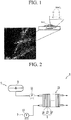
- FIG. 1 is a SEM photograph of the supporter for a fuel cell and a schematic view showing the structure of the supporter.
- the carbonaceous material comprises carbon nanotubes with optionally at least one selected from graphite, denka black, ketjen black, acetylene black, carbon nanofiber, carbon nanowire, carbon nanoballs, and activated carbon.
- the transition metal oxide comprises ZrO 2 , optionally in combination with SnO 2 , WO 3 , TiO 2 , or InO 2 , and optionally the composite metal oxide includes at least two selected from Zr, Sn, W, Ti, or In with the proviso that it comprises ZrO 2 .
- the transition metal oxide has an average size of 1.5 nm to 10 nm.
- the amount of the transition metal oxide is 4 wt% to 96 wt% (e.g. 5 wt% to 95 wt%) based on 100 wt% of the total supporter, and in another embodiment, 30 wt% to 50 wt%. When the amount of the transition metal oxide falls in the above ranges, the supporter exhibits good stability and electrical conductivity.
- the amount of transition metal oxide is optionally between 10 wt% to 90 wt%, 15 wt% to 85 wt%, such as 20 wt% to 70 wt%, (e.g. 25 wt% to 60 wt%).
- the supporter includes the coating layer including the carbonaceous material and metal oxide, so it has advantageous of high conductivity owing to the carbonaceous material and thermal/electrochemical stability owing to the metal oxide.
- the carbonaceous material and the metal oxide are covalently bonded, it is advantageous for preventing separation of the metal oxide from the supporter while working for a long time.
- Another embodiment provides a method of preparing the supporter, wherein the method comprises mixing a transition metal oxide precursor comprising a Zr-containing acetylacetonate, acetate, chloride, or a combination thereof and the carbonaceous material in the presence of a solvent selected from ethanol, water, isopropyl alcohol, or a combination thereof and the mixing ratio of the transition metal precursor and the carbonaceous material is controlled to obtain a mixing ratio of the transition metal oxide and the carbonaceous material that is 4:96 to 96:4 wt% and the mixing step is performed at 90 °C to 200 °C.
- the carbonaceous material is optionally one oxidized by acids.
- the acid used is optionally selected from nitric acid, sulfuric acid, or a combination thereof.
- the oxidization includes mixing/refluxing the carbonaceous material and the acid and washing/drying.
- the acid used has a concentration of 0.1 M to 3 M.
- the transition metal precursor is a transition metal-included acetylacetonate, acetate, chloride, or a combination thereof.
- the transition metal comprises Zr, optionally in combination with Sn, W, Ti, or In.
- the carbonaceous material comprises carbon nanotubes (optionally single-wall carbon nanotubes or multi-wall carbon nanotubes), optionally with at least one selected from graphite, denka black, ketjen black, acetylene black, carbon nanofiber, carbon nanowire, carbon nanoballs, or activated carbon.
- the carbonaceous material comprises carbon nanotubes in combination with carbon nanofiber or carbon nanowire.
- a mixing ratio of the transition metal precursor and the carbonaceous material is preferably from 5:95: to 95:5 wt%. In another embodiment, the mixing ratio of the transition metal precursor and the carbonaceous material is from 30:70 to 50:50 wt%.
- the mixing ratio of the transition metal precursor and the carbonaceous material is out of the above range, i.e., the amount of the transition metal precursor decreases, sufficient durability cannot be obtained. Furthermore, as the amount of the transition metal precursor increases, the electrical conductivity may be reduced.
- the mixing ratio is performed at 90°C to 200°C.
- the mixing ratio at the above temperature allows rapid synthesis and termination reaction, thereby reducing the particle size.
- the transition metal precursor is adhered to a surface of the carbonaceous material and converted into a transition metal alkoxide.
- the transition metal precursor reacts with the "-OH” or "-O" functional group on the surface of the carbonaceous material to adhere to the surface of the carbonaceous material, thereby converting the transition metal alkoxide.
- Another embodiment provides a catalyst for a fuel cell including the supporter and an active metal supported on the supporter.
- the active metal is preferably at least one selected from platinum, ruthenium, osmium, a platinum/ruthenium alloy, a platinum/osmium alloy, a platinum/palladium alloy, a platinum/M alloy (M is a transition element of Ga, Ti, V, Cr, Mn, Fe, Co, Ni, Cu, Zn, Sn, Mo, W, Rh, Ru, or a combination thereof), or a combination thereof.
- M is a transition element of Ga, Ti, V, Cr, Mn, Fe, Co, Ni, Cu, Zn, Sn, Mo, W, Rh, Ru, or a combination thereof
- the catalyst according to another embodiment is used for an anode and/or a cathode. The catalyst can be the same regardless of whether it is used in the anode or the cathode.
- a direct oxidation fuel cell optionally includes a platinum-ruthenium alloy as the active metal as an anode catalyst in order to prevent catalyst poisoning due to CO generated during the anode reaction.
- the catalyst include Pt, Pt/Ru, Pt/W, Pt/Ni, Pt/Sn, Pt/Mo, Pt/Pd, Pt/Fe, Pt/Cr, Pt/Co, Pt/Ru/W, Pt/Ru/Mo, Pt/Ru/V, Pt/Fe/Co, Pt/Ru/Rh/Ni, Pt/Ru/Sn/W, and a combination thereof, but are not limited thereto.
- the method of supporting the active metal on the supporter is well-known in the related field, and a detailed description thereof is omitted.
- Another embodiment provides an electrode for a fuel cell including a catalyst layer including the catalyst and an electrode substrate.
- the catalyst layer optionally further includes a binder resin to improve its adherence and proton transfer properties.
- the binder resin (referred as "ionomer”) is optionally a proton conductive polymer resin having a cation exchange group selected from the group consisting of a sulfonic acid group, a carboxylic acid group, a phosphoric acid group, a phosphonic acid group, and derivatives thereof at its side chain.
- the polymer examples include at least one proton conductive polymer selected from the group consisting of a fluorine-based polymer, a benzimidazole-based polymer, a polyimide-based polymer, a polyetherimide-based polymer, a polyphenylenesulfide-based polymer, a polysulfone-based polymer, a polyethersulfone-based polymer, a polyetherketone-based polymer, a polyether-etherketone-based polymer, or a polyphenylquinoxaline-based polymer.
- a fluorine-based polymer a benzimidazole-based polymer
- a polyimide-based polymer a polyetherimide-based polymer
- a polyphenylenesulfide-based polymer a polysulfone-based polymer
- a polyethersulfone-based polymer a polyetherketone-based polymer
- a polyether-etherketone-based polymer
- the proton conductive polymer is at least one selected from the group consisting of poly(perfluorosulfonic acid), poly(perfluorocarboxylic acid), a sulfonic acid-containing copolymer of tetrafluoroethylene and fluorovinylether, polyetherketone sulfide, an aryl ketone, poly(2,2'-m-phenylene)-5,5'-bibenzimidazole, and poly(2,5-benzimidazole).
- the hydrogen (H) in the cation exchange group of the proton conductive polymer is optionally substituted with Na, K, Li, Cs, or tetrabutylammonium.
- H in the cation exchange group of the terminal end of the proton conductive polymer side chain is substituted with Na or tetrabutylammonium
- NaOH or tetrabutylammonium hydroxide is optionally used during preparation of the catalyst composition, respectively.
- K, Li, or Cs a suitable compound for the substitution is used. Since such a substitution is known in this art, a detailed description thereof is omitted.
- the binder resins are used singularly or in combination. They are optionally used along with non-conductive polymers to improve adherence with a polymer electrolyte membrane.
- the binder resins are used in a controlled amount to adapt to their purposes.
- non-conductive polymers include at least one selected from the group consisting of polytetrafluoroethylene (PTFE), a tetrafluoroethylene-hexafluoropropylene copolymer (FEP), a tetrafluoroethylene-perfluoroalkylvinylether copolymer (PFA), an ethylene/tetrafluoroethylene copolymer (ETFE), an ethylenechlorotrifluoro-ethylene copolymer (ECTFE), polyvinylidenefluoride, a copolymer of polyvinylidenefluoride-hexafluoropropylene (PVdF-HFP), dodecylbenzenesulfonic acid, and sorbitol.
- PTFE polytetrafluoroethylene
- FEP tetrafluoroethylene-hexafluoropropylene copolymer
- PFA tetrafluoroethylene-perfluoroalkylvinylether
- the electrode substrates support the anode and cathode and provide a path for transferring the fuel and oxidant to catalyst layers.
- the electrode substrates are formed from a material such as carbon paper, carbon cloth, carbon felt, or a metal cloth (a porous film composed of metal fiber or a metal film disposed on a surface of a cloth composed of polymer fibers).
- the electrode substrate is not limited thereto.
- the electrode substrates may be treated with a fluorine-based resin to be water-repellent to prevent deterioration of reactant diffusion efficiency due to water generated during operation of a fuel cell.
- the fluorine-based resin examples include polytetrafluoroethylene, polyvinylidene fluoride, polyhexafluoropropylene, polyperfluoroalkylvinylether, polyperfluorosulfonylfluoride, alkoxyvinyl ether, fluorinated ethylene propylene, polychlorotrifluoroethylene, and copolymers thereof.
- the electrode for a fuel cell optionally further includes a microporous layer to increase reactant diffusion effects of the electrode substrate.
- the microporous layer generally includes conductive powders with a particular particle diameter, for example carbon powder, carbon black, acetylene black, activated carbon, carbon fiber, fullerene, carbon nanotubes, carbon nanowire, carbon nanohorns, or carbon nanorings.
- the microporous layer is formed by coating a composition including a conductive powder, a binder resin, and a solvent on the electrode substrate.
- the binder resin optionally includes polytetrafluoroethylene, polyvinylidenefluoride, polyhexafluoropropylene, polyperfluoroalkylvinylether, polyperfluorosulfonylfluoride, alkoxyvinyl ether, polyvinylalcohol, celluloseacetate, a copolymer thereof, and the like.
- the binder resin may optionally includes polytetrafluoroethylene, polyvinylidenefluoride, polyhexafluoropropylene, polyperfluoroalkylvinylether, polyperfluorosulfonylfluoride, alkoxyvinyl ether, polyvinylalcohol, celluloseacetate, a copolymer thereof, and the like.
- the coating method used can be selected from, but is not limited to, screen printing, spray coating, doctor blade methods, gravure coating, dip coating, silk screening, painting, and so on, depending on the viscosity of the composition.
- a membrane-electrode assembly for a fuel cell including the electrode as at least one of a cathode and an anode is provided.
- the membrane-electrode assembly includes an anode and a cathode facing each other, and a polymer electrolyte membrane disposed between the anode and cathode.
- the polymer electrolyte membrane may include any kind generally used for a fuel cell, formed of a polymer resin, and having proton conductivity, without any particular limit.
- Examples thereof include a polymer resin having a cation exchange group selected from a sulfonic acid group, a carboxylic acid group, a phosphoric acid group, a phosphonic acid group, and derivatives thereof, at the side chain.
- the polymer resin may include at least one selected from a fluorine-based polymer, a benzimidazole-based polymer, a polyimide-based polymer, a polyetherimide-based polymer, a polyphenylenesulfide-based polymer, a polysulfone-based polymer, a polyethersulfone-based polymer, a polyetherketone-based polymer, a polyether-etherketone-based polymer, and a polyphenylquinoxaline-based polymer.
- Preferred examples include poly(perfluorosulfonic acid) (generally, commercially available as Nafion), poly(perfluorocarboxylic acid), a copolymer of tetrafluoroethylene having a sulfonic acid group and fluorovinylether, defluorinated polyetherketone sulfide, aryl ketone, poly(2,2'-(m-phenylene)-5,5'-bibenzimidazole, poly(2,5-benzimidazole), and the like.
- poly(perfluorosulfonic acid) generally, commercially available as Nafion
- poly(perfluorocarboxylic acid) a copolymer of tetrafluoroethylene having a sulfonic acid group and fluorovinylether, defluorinated polyetherketone sulfide, aryl ketone, poly(2,2'-(m-phenylene)-5,5'-bibenzimidazole,
- the hydrogen (H) is substituted with Na, K, Li, Cs, or tetrabutylammonium in a proton conductive group of the proton conductive polymer.
- NaOH is used.
- tributylammonium hydroxide is used.
- K, Li, or Cs can also be substituted with use of appropriate compounds.
- a method of substituting hydrogen (H) is known in the related art, and therefore is not further described in detail.
- the proton conductive polymer including substituted Na, K, Li, Cs, or tetrabutylammonium is converted into a proton type during the acid treatment of a catalyst layer.
- a fuel cell system including at least one electricity generating element, a fuel supplier, and an oxidant supplier.
- the electricity generating element includes the membrane-electrode assembly according to one embodiment and a separator (referred to as a "bipolar plate").
- the electricity generating element generates electrical energy through oxidation of a fuel and reduction of an oxidant.
- the fuel supplier supplies the fuel to the electricity generating element and the oxidant supplier supplies the oxidant such as air or oxygen to the electricity generating element.
- the fuel includes hydrogen or a hydrocarbon fuel in the form of a gas or liquid. Examples thereof include methanol, ethanol, propanol, butanol, natural gas, and the like.
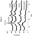
- FIG. 2 shows a fuel cell system supplying a fuel and an oxidant to an electricity generating element using a pump, but the fuel cell system according to the embodiment is not limited to such structures.
- the fuel cell system of the embodiment alternately includes a structure wherein a fuel and an oxidant are provided in a diffusion manner without a pump.
- the fuel system 1 includes at least one electricity generating element 3 that generates electrical energy by oxidation of a fuel and reduction of an oxidant, a fuel supplier 5 for supplying the fuel, and an oxidant supplier 7 for supplying an oxidant to the electricity generating element 3.
- the fuel supplier 5 is equipped with a tank 9, which stores fuel, and a fuel pump 11, which is connected therewith.
- the fuel pump 11 supplies fuel that is stored in the tank 9 with a predetermined pumping power.
- the oxidant supplier 7, which supplies the electricity generating element 3 with an oxidant, is equipped with at least one oxidant pump 13 for supplying an oxidant with a predetermined pumping power.
- the electricity generating element 3 includes a membrane-electrode assembly 17, which oxidizes hydrogen or a fuel and reduces an oxidant, and separators 19 and 19' that are respectively positioned at opposite sides of the membrane-electrode assembly and that supply hydrogen or a fuel, and an oxidant, respectively.
- a stack 15 is provided by stacking at least one electricity generating element 3.
- Zirconium (IV) acetylacetonate and carbon black (CB-1) were mixed under an ethanol reducing agent at 200 °C to produce a reaction.
- the mixing ratio of zirconium (IV) acetylacetonate and multi-wall carbon nanotubes was 12 wt%:88 wt%.
- the ethanol reduction provided a supporter with a zirconium oxide-included coating layer on a surface of the multi-wall carbon nanotubes, and the multi-wall carbon nanotubes and zirconium oxide were covalently bonded.
- a supporter for a fuel cell was prepared by the same procedure as in Reference Example 1, except that the mixing ratio of zirconium (IV) acetylacetonate and carbon black (CB-1) was 35 wt%:65 wt%.
- a supporter for a fuel cell was prepared by the same procedure as in Reference Example 1, except that the mixing ratio of zirconium (IV) acetylacetonate and carbon black (CB-1) was 50 wt%:50 wt%.
- a supporter for a fuel cell was prepared by the same procedure as in Reference Example 1, except that the mixing ratio of zirconium (IV) acetylacetonate and carbon black (CB-1) was 70 wt%:30 wt%.
- a supporter for a fuel cell was prepared by the same procedure as in Reference Example 1, except that the mixing ratio of zirconium (IV) acetylacetonate and carbon black (CB-1) was 80 wt%:20 wt%.
- a supporter for a fuel cell was prepared by the same procedure as in Reference Example 1, except that crystalline carbon black (CB-500) which was prepared by heat-treating carbon black (CB-1) at 2000 °C was used instead of carbon black (CB-1).
- CB-500 crystalline carbon black
- CB-1 carbon black
- a supporter for a fuel cell was prepared by the same procedure as in Reference Example 1, except that crystalline carbon black (CB-1000) which was prepared by heat-treating carbon black (CB-1) at 2500 °C was used instead of carbon black (CB-1).
- CB-1000 crystalline carbon black
- CB-1 carbon black
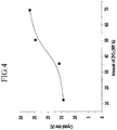
- the X-ray diffraction for the supporters according to Reference Example 1 and Examples 1 to 3 was measured using CuK ⁇ radiation. The results are shown in FIG. 3 . As shown in FIG. 3 , as the amount of zirconium (IV) acetylacetonate increases, the intensity of the peaks of t-ZrO 2 (200) and t-ZrO 2 (111) increases. It can be known from the result that the tetragonal structure is uniformly formed.
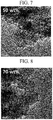
- the size of ZrO 2 in the supporter according Reference Example 1 and Examples 1 to 3 was measured. The results are shown in FIG. 4 . As shown in FIG. 4 , as the amount of zirconium (IV) acetylacetonate, i.e., the amount of ZrO 2 in the supporter increases, the particle size increases. In FIG. 4 , the amount of ZrO 2 shown is based upon the weight percentage of zirconium (IV) acetylacetonate used to manufacture the supporter.
- FIGS. 5 to 8 TEM photographs (400,000-times enlarged) of the supporter according to Reference Example 1 and Examples 1 to 3 are shown in FIGS. 5 to 8 , respectively. It can be known from FIGS. 5 to 8 that the bright portions are wider as the amount of zirconium (IV) acetylacetonate is increased. The brighten portions in FIGS. 5 to 8 indicate zirconium oxide so that as the amount of zirconium (IV) acetylacetonate increases, the dispersion ability improves.
- Pt was supported on the supporter according to Example 4 by a polyol method to prepare a Pt/Zr-carbon black catalyst (Pt/Zr-CB-1).
- a catalyst (Pt/Zr-CB-500) was prepared by the same procedure as in Example 7, except that the supporter according to Example 5 was used.
- a catalyst (Pt/Zr-CB-1000) was prepared by the same procedure as in Example 7, except that the supporter according to Example 6 was used.
- Pt was supported on a carbon black (CB-1) by a polyol method to prepare a catalyst (Pt/CB-1).
- FIG. 9 and FIGS. 10A to 10D 500,000-times enlarged TEM photographs of the catalyst according to Example 7 are shown in FIG. 9 and FIGS. 10A to 10D .
- the TEM photographs in FIG. 9 and FIGS. 10A to 10D were obtained from various surfaces of the catalyst according to Example 7. They indicate that Pt and ZrO 2 are uniformly distributed in the total catalyst.
- Example 7 and Comparative Example 1 The catalyst activity of the catalyst according to Examples 7 to 9 and Comparative Examples 1 to 3 was measured.
- the results according to Example 7 and Comparative Example 1 are shown in FIG. 11
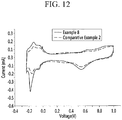
- the results according to Example 8 and Comparative Example 2 are shown in FIG. 12
- the results according to Example 9 and Comparative Example 3 are shown in FIG. 13 .
- the catalyst activity was obtained by a CV (cyclic voltammetry) experiment.
- a saturated calomel electrode (SCE) was used as a standard electrode.
- the working electrode obtained by mixing 50 wt% of the catalyst and 50 wt% of an ionomer in an isopropyl alcohol solvent to prepare a catalyst ink slurry and coating the ink slurry on a glassy carbon rod was used.
- a Pt mesh was used as a counter electrode.
- the CV experiment was performed in an aqueous solution of 0.1 M HClO 4 and measured at a scan rate of 10 mV/second.
- the activated surface areas of catalysts according to Example 7 and Comparative Example 1 were measured by an electrochemical experiment.
- the activated surface area percentages (%) after 1000 cycles were calculated based on 100 % of the activated surface area of the catalyst.
- a supporter for a fuel cell was prepared by the same procedure as in Reference Example 1, except that Sn acetylacetonate was used instead of zirconium (IV) acetylacetonate, and the mixing ratio of Sn acetylacetonate and carbon black (CB-1) was 30 wt%:70 wt%.
- a supporter for a fuel cell was prepared by the same procedure as in Reference Example 1, except that W chloride was used instead of zirconium (IV) acetylacetonate, and the mixing ratio ofW chloride and carbon black (CB-1) was 10 wt%:90 wt%.
- FIG. 15 A TEM photograph of the catalyst according to Example 10 is shown in FIG. 15 . As shown in FIG. 15 , Pt and Sn were uniformly distributed in the total catalyst.
- FIG. 16 is a TEM photograph of the catalyst according to Example 11. As shown in FIG. 16 , Pt and W were uniformly distributed in the total catalyst.
Landscapes
- Chemical & Material Sciences (AREA)
- Chemical Kinetics & Catalysis (AREA)
- Electrochemistry (AREA)
- General Chemical & Material Sciences (AREA)
- Engineering & Computer Science (AREA)
- Materials Engineering (AREA)
- Life Sciences & Earth Sciences (AREA)
- Manufacturing & Machinery (AREA)
- Sustainable Development (AREA)
- Sustainable Energy (AREA)
- Organic Chemistry (AREA)
- Inert Electrodes (AREA)
- Fuel Cell (AREA)
- Catalysts (AREA)
Description
- The disclosure relates to a supporter for a fuel cell and a method of preparing the same, and an electrode, a membrane-electrode assembly, and a fuel cell system including the same.
- A fuel cell is a power generation system for producing electrical energy through a chemical reaction of an oxidant and hydrogen from a hydrocarbon-based material such as methanol, ethanol, or natural gas. Such a fuel cell is a clean energy source with the potential to replace fossil fuels.
- Fuel cells include a stack composed of unit cells, and produce various ranges of power. Since it has four to ten times higher energy density than a small lithium battery, it has been highlighted as a small portable power source.
- Typical examples of fuel cells are polymer electrolyte membrane fuel cells (PEMFC) and direct oxidation fuel cells (DOFC). A direct oxidation fuel cell that uses methanol as a fuel is called a direct methanol fuel cell (DMFC). The polymer electrolyte fuel cell has an advantage of high energy density and high power, and a direct oxidation fuel cell has lower energy density than that of the polymer electrolyte fuel cell, but it has the advantages of easy handling of a fuel, being capable of operating at room temperature due to its low operation temperature, and no need for additional fuel reforming processors.
- In the above-mentioned fuel cell system, the stack that generates electricity substantially includes several to scores of unit cells stacked adjacent to one another, and each unit cell is formed of a membrane-electrode assembly (MEA) and a separator (also referred to as a bipolar plate). The membrane-electrode assembly is composed of an anode (also referred to as a "fuel electrode" or an "oxidation electrode") and a cathode (also referred to as an "air electrode" or a "reduction electrode") that are separated by a polymer electrolyte membrane. A fuel is supplied to the anode and adsorbed on catalysts of the anode, and the fuel is oxidized to produce protons and electrons. The electrons are transferred into the cathode via an external circuit, and the protons are transferred into the cathode through the polymer electrolyte membrane. In addition, an oxidant is supplied to the cathode, and then the oxidant, protons, and electrons react on catalysts of the cathode to produce electricity along with water.
EP1883131 discloses a supported catalyst for a fuel cell.JP2008-181696 US2011/151354 discloses an electrode catalyst for a fuel cell. - An embodiment of the present invention provides a supporter for a fuel cell exhibiting good stability as claimed in
claim 1. - Another embodiment of the present invention provides a method of preparing the supporter for a fuel cell as claimed in
claim 2. - Yet another embodiment of the present invention provides an electrode for a fuel cell including the supporter as claimed in
claim 7. - Still another embodiment of the present invention provides a membrane-electrode assembly for a fuel cell including the electrode as claimed in
claim 8. Still another embodiment of the present invention provides a fuel cell system including the membrane-electrode assembly as claimed inclaim 9. - According to the present invention, a supporter for a fuel cell is provided that includes a carbonaceous material and a transition metal oxide coating layer formed on a surface of the carbonaceous material, wherein the surface of the carbonaceous material is covalently bonded with the transition metal oxide and the transition metal oxide has an average particle size of 1.5 nm to 10 nm.
- The carbonaceous material comprises carbon nanotubes, optionally with at least one of graphite, denka black, ketjen black, acetylene black, carbon nanofiber, carbon nanowire, carbon nanoballs, and activated carbon.
- The transition metal oxide is ZrO2. Optionally, this may be in combination with SnO2, WO3, TiO2, or InO2. In another embodiment, the transition metal oxide is a composite metal oxide including at least two of Zr, Sn, W, Ti, and In but with the proviso that it comprises ZrO2.
- The amount of the transition metal oxide is preferably between 5 wt% to 95 wt% based on 100 wt% of the supporter.
- Another embodiment of the present invention provides the supporter and an active metal supported on the supporter.
- The active metal is preferably at least one selected from platinum, ruthenium, osmium, a platinum/ruthenium alloy, a platinum/osmium alloy, a platinum/palladium alloy, a platinum/M alloy (M is a transition element of Ga, Ti, V, Cr, Mn, Fe, Co, Ni, Cu, Zn, Sn, Mo, W, Rh, Ru, or a combination thereof), or a combination thereof.
- Another embodiment of the present invention provides a method of preparing the supporter for a fuel cell, including mixing a transition metal precursor and the carbonaceous material in the presence of a solvent. Still another embodiment provides an electrode for a fuel cell including an electrode substrate and a catalyst layer on the electrode substrate, and the catalyst layer includes the supporter.
- Still another embodiment provides a membrane-electrode assembly for a fuel cell comprising the electrode as at least one of a cathode and an anode. For example, the embodiment may relate to a membrane-electrode assembly including an anode and a cathode facing each other, and a polymer electrolyte membrane interposed between the cathode and the anode, wherein at least one of the cathode and the anode is the electrode.
- According to a further embodiment of the present invention, provided is a fuel cell system that includes at least one electricity generating element including the membrane-electrode assembly and separators positioned at each side of the membrane-electrode assembly, a fuel supplier, and an oxidant supplier. The electricity generating element generates electrical energy through oxidation of a fuel and reduction of an oxidant. Furthermore, the fuel supplier supplies the fuel to the electricity generating element and the oxidant supplier supplies the oxidant to the electricity generating element. The supporter for a fuel cell according to one embodiment may provide a catalyst exhibiting good stability, activity, and cycle-life characteristics.
-
-
FIG. 1 is a SEM photograph of the supporter for a fuel cell and a schematic view showing a supporter according to one embodiment. -
FIG. 2 is a schematic view showing the structure of a fuel cell system according to one embodiment. -
FIG. 3 is a graph showing X-ray diffraction results of the supporter according to Reference Example 1 and Examples 1 to 3. -
FIG. 4 is a graph showing a size of ZrO2 in the supporter according to Reference Example 1 and Examples 1 to 3. -
FIG. 5 is a TEM photograph of the supporter according to Reference Example 1. -
FIG. 6 is a TEM photograph of the supporter according to Example 1. -
FIG. 7 is a TEM photograph of the supporter according to Example 2. -
FIG. 8 is a TEM photograph of the supporter according to Example 3. -
FIG. 9 is a 500,000-times enlarged TEM photograph of the catalyst according to Example 7. -
FIG. 10A to FIG. 10D are 500,000-times enlarged SEM photographs according to Example 7. -
FIG. 11 is a graph exhibiting activities of the catalysts according to Example 7 and Comparative Example 1. -
FIG. 12 is a graph exhibiting activities of the catalysts according to Example 8 and Comparative Example 2. -
FIG. 13 is a graph exhibiting activities of the catalysts according to Example 9 and Comparative Example 3. -
FIG. 14 is a graph exhibiting an active surface area of the catalysts according to Example 7 and Comparative Example 1. -
FIG. 15 is a SEM photograph of the catalyst according to Example 10 - Reference. -
FIG. 16 is a SEM photograph of the catalyst according to Example 11 - Reference. - One embodiment provides a supporter for a fuel cell that includes a carbonaceous material and a transition metal oxide coating layer on a surface of the supporter, wherein the transition metal oxide has an average particle size 1.5 nm to 10 nm. The carbonaceous material and the transitional metal oxide are covalently bonded.
-
FIG. 1 is a SEM photograph of the supporter for a fuel cell and a schematic view showing the structure of the supporter. - The carbonaceous material comprises carbon nanotubes with optionally at least one selected from graphite, denka black, ketjen black, acetylene black, carbon nanofiber, carbon nanowire, carbon nanoballs, and activated carbon.
- The transition metal oxide comprises ZrO2, optionally in combination with SnO2, WO3, TiO2, or InO2, and optionally the composite metal oxide includes at least two selected from Zr, Sn, W, Ti, or In with the proviso that it comprises ZrO2. The transition metal oxide has an average size of 1.5 nm to 10 nm.
- The amount of the transition metal oxide is 4 wt% to 96 wt% (e.g. 5 wt% to 95 wt%) based on 100 wt% of the total supporter, and in another embodiment, 30 wt% to 50 wt%. When the amount of the transition metal oxide falls in the above ranges, the supporter exhibits good stability and electrical conductivity.
- The amount of transition metal oxide is optionally between 10 wt% to 90 wt%, 15 wt% to 85 wt%, such as 20 wt% to 70 wt%, (e.g. 25 wt% to 60 wt%).
- The supporter according to one embodiment includes the coating layer including the carbonaceous material and metal oxide, so it has advantageous of high conductivity owing to the carbonaceous material and thermal/electrochemical stability owing to the metal oxide. In particular, since the carbonaceous material and the metal oxide are covalently bonded, it is advantageous for preventing separation of the metal oxide from the supporter while working for a long time.
- Another embodiment provides a method of preparing the supporter, wherein the method comprises mixing a transition metal oxide precursor comprising a Zr-containing acetylacetonate, acetate, chloride, or a combination thereof and the carbonaceous material in the presence of a solvent selected from ethanol, water, isopropyl alcohol, or a combination thereof and the mixing ratio of the transition metal precursor and the carbonaceous material is controlled to obtain a mixing ratio of the transition metal oxide and the carbonaceous material that is 4:96 to 96:4 wt% and the mixing step is performed at 90 °C to 200 °C. The carbonaceous material is optionally one oxidized by acids. The acid used is optionally selected from nitric acid, sulfuric acid, or a combination thereof.
- The oxidization includes mixing/refluxing the carbonaceous material and the acid and washing/drying. The acid used has a concentration of 0.1 M to 3 M.
- According to this process, a "-OH" or "-O" functional group is presented on a surface of the carbonaceous material.
- The transition metal precursor is a transition metal-included acetylacetonate, acetate, chloride, or a combination thereof. The transition metal comprises Zr, optionally in combination with Sn, W, Ti, or In.
- The carbonaceous material comprises carbon nanotubes (optionally single-wall carbon nanotubes or multi-wall carbon nanotubes), optionally with at least one selected from graphite, denka black, ketjen black, acetylene black, carbon nanofiber, carbon nanowire, carbon nanoballs, or activated carbon. Suitably, the carbonaceous material comprises carbon nanotubes in combination with carbon nanofiber or carbon nanowire.
- A mixing ratio of the transition metal precursor and the carbonaceous material is preferably from 5:95: to 95:5 wt%. In another embodiment, the mixing ratio of the transition metal precursor and the carbonaceous material is from 30:70 to 50:50 wt%. When the mixing ratio of the transition metal precursor and the carbonaceous material is out of the above range, i.e., the amount of the transition metal precursor decreases, sufficient durability cannot be obtained. Furthermore, as the amount of the transition metal precursor increases, the electrical conductivity may be reduced.
- The mixing ratio is performed at 90°C to 200°C. The mixing ratio at the above temperature allows rapid synthesis and termination reaction, thereby reducing the particle size.
- According to the above procedure, the transition metal precursor is adhered to a surface of the carbonaceous material and converted into a transition metal alkoxide. Particularly, if the carbonaceous material oxidized with acid is used, the transition metal precursor reacts with the "-OH" or "-O" functional group on the surface of the carbonaceous material to adhere to the surface of the carbonaceous material, thereby converting the transition metal alkoxide.
- Another embodiment provides a catalyst for a fuel cell including the supporter and an active metal supported on the supporter.
- The active metal is preferably at least one selected from platinum, ruthenium, osmium, a platinum/ruthenium alloy, a platinum/osmium alloy, a platinum/palladium alloy, a platinum/M alloy (M is a transition element of Ga, Ti, V, Cr, Mn, Fe, Co, Ni, Cu, Zn, Sn, Mo, W, Rh, Ru, or a combination thereof), or a combination thereof. The catalyst according to another embodiment is used for an anode and/or a cathode. The catalyst can be the same regardless of whether it is used in the anode or the cathode. However, a direct oxidation fuel cell optionally includes a platinum-ruthenium alloy as the active metal as an anode catalyst in order to prevent catalyst poisoning due to CO generated during the anode reaction. Specific examples of the catalyst include Pt, Pt/Ru, Pt/W, Pt/Ni, Pt/Sn, Pt/Mo, Pt/Pd, Pt/Fe, Pt/Cr, Pt/Co, Pt/Ru/W, Pt/Ru/Mo, Pt/Ru/V, Pt/Fe/Co, Pt/Ru/Rh/Ni, Pt/Ru/Sn/W, and a combination thereof, but are not limited thereto.
- The method of supporting the active metal on the supporter is well-known in the related field, and a detailed description thereof is omitted.
- Another embodiment provides an electrode for a fuel cell including a catalyst layer including the catalyst and an electrode substrate.
- The catalyst layer optionally further includes a binder resin to improve its adherence and proton transfer properties.
- The binder resin (referred as "ionomer") is optionally a proton conductive polymer resin having a cation exchange group selected from the group consisting of a sulfonic acid group, a carboxylic acid group, a phosphoric acid group, a phosphonic acid group, and derivatives thereof at its side chain.
- Examples of the polymer include at least one proton conductive polymer selected from the group consisting of a fluorine-based polymer, a benzimidazole-based polymer, a polyimide-based polymer, a polyetherimide-based polymer, a polyphenylenesulfide-based polymer, a polysulfone-based polymer, a polyethersulfone-based polymer, a polyetherketone-based polymer, a polyether-etherketone-based polymer, or a polyphenylquinoxaline-based polymer.
- In one embodiment, the proton conductive polymer is at least one selected from the group consisting of poly(perfluorosulfonic acid), poly(perfluorocarboxylic acid), a sulfonic acid-containing copolymer of tetrafluoroethylene and fluorovinylether, polyetherketone sulfide, an aryl ketone, poly(2,2'-m-phenylene)-5,5'-bibenzimidazole, and poly(2,5-benzimidazole).
- The hydrogen (H) in the cation exchange group of the proton conductive polymer is optionally substituted with Na, K, Li, Cs, or tetrabutylammonium. When the H in the cation exchange group of the terminal end of the proton conductive polymer side chain is substituted with Na or tetrabutylammonium, NaOH or tetrabutylammonium hydroxide is optionally used during preparation of the catalyst composition, respectively. When the H is substituted with K, Li, or Cs, a suitable compound for the substitution is used. Since such a substitution is known in this art, a detailed description thereof is omitted.
- The binder resins are used singularly or in combination. They are optionally used along with non-conductive polymers to improve adherence with a polymer electrolyte membrane. The binder resins are used in a controlled amount to adapt to their purposes.
- Examples of the non-conductive polymers include at least one selected from the group consisting of polytetrafluoroethylene (PTFE), a tetrafluoroethylene-hexafluoropropylene copolymer (FEP), a tetrafluoroethylene-perfluoroalkylvinylether copolymer (PFA), an ethylene/tetrafluoroethylene copolymer (ETFE), an ethylenechlorotrifluoro-ethylene copolymer (ECTFE), polyvinylidenefluoride, a copolymer of polyvinylidenefluoride-hexafluoropropylene (PVdF-HFP), dodecylbenzenesulfonic acid, and sorbitol.
- The electrode substrates support the anode and cathode and provide a path for transferring the fuel and oxidant to catalyst layers. In one embodiment, the electrode substrates are formed from a material such as carbon paper, carbon cloth, carbon felt, or a metal cloth (a porous film composed of metal fiber or a metal film disposed on a surface of a cloth composed of polymer fibers). The electrode substrate is not limited thereto.
- The electrode substrates may be treated with a fluorine-based resin to be water-repellent to prevent deterioration of reactant diffusion efficiency due to water generated during operation of a fuel cell.
- Examples of the fluorine-based resin include polytetrafluoroethylene, polyvinylidene fluoride, polyhexafluoropropylene, polyperfluoroalkylvinylether, polyperfluorosulfonylfluoride, alkoxyvinyl ether, fluorinated ethylene propylene, polychlorotrifluoroethylene, and copolymers thereof. The electrode for a fuel cell optionally further includes a microporous layer to increase reactant diffusion effects of the electrode substrate. The microporous layer generally includes conductive powders with a particular particle diameter, for example carbon powder, carbon black, acetylene black, activated carbon, carbon fiber, fullerene, carbon nanotubes, carbon nanowire, carbon nanohorns, or carbon nanorings. The microporous layer is formed by coating a composition including a conductive powder, a binder resin, and a solvent on the electrode substrate.
- The binder resin optionally includes polytetrafluoroethylene, polyvinylidenefluoride, polyhexafluoropropylene, polyperfluoroalkylvinylether, polyperfluorosulfonylfluoride, alkoxyvinyl ether, polyvinylalcohol, celluloseacetate, a copolymer thereof, and the like. The binder resin may optionally includes polytetrafluoroethylene, polyvinylidenefluoride, polyhexafluoropropylene, polyperfluoroalkylvinylether, polyperfluorosulfonylfluoride, alkoxyvinyl ether, polyvinylalcohol, celluloseacetate, a copolymer thereof, and the like.
- The coating method used can be selected from, but is not limited to, screen printing, spray coating, doctor blade methods, gravure coating, dip coating, silk screening, painting, and so on, depending on the viscosity of the composition.
- According to another embodiment, a membrane-electrode assembly for a fuel cell including the electrode as at least one of a cathode and an anode is provided.
- The membrane-electrode assembly includes an anode and a cathode facing each other, and a polymer electrolyte membrane disposed between the anode and cathode. The polymer electrolyte membrane may include any kind generally used for a fuel cell, formed of a polymer resin, and having proton conductivity, without any particular limit.
- Examples thereof include a polymer resin having a cation exchange group selected from a sulfonic acid group, a carboxylic acid group, a phosphoric acid group, a phosphonic acid group, and derivatives thereof, at the side chain. Examples of the polymer resin may include at least one selected from a fluorine-based polymer, a benzimidazole-based polymer, a polyimide-based polymer, a polyetherimide-based polymer, a polyphenylenesulfide-based polymer, a polysulfone-based polymer, a polyethersulfone-based polymer, a polyetherketone-based polymer, a polyether-etherketone-based polymer, and a polyphenylquinoxaline-based polymer.
- Preferred examples include poly(perfluorosulfonic acid) (generally, commercially available as Nafion), poly(perfluorocarboxylic acid), a copolymer of tetrafluoroethylene having a sulfonic acid group and fluorovinylether, defluorinated polyetherketone sulfide, aryl ketone, poly(2,2'-(m-phenylene)-5,5'-bibenzimidazole, poly(2,5-benzimidazole), and the like.
- The hydrogen (H) is substituted with Na, K, Li, Cs, or tetrabutylammonium in a proton conductive group of the proton conductive polymer. When the hydrogen (H) is substituted with Na in an ion exchange group at the terminal end of the proton conductive group, NaOH is used. When the hydrogen (H) is substituted with tetrabutylammonium, tributylammonium hydroxide is used. K, Li, or Cs can also be substituted with use of appropriate compounds.
- A method of substituting hydrogen (H) is known in the related art, and therefore is not further described in detail. In addition, the proton conductive polymer including substituted Na, K, Li, Cs, or tetrabutylammonium is converted into a proton type during the acid treatment of a catalyst layer.
- According to another embodiment, a fuel cell system including at least one electricity generating element, a fuel supplier, and an oxidant supplier is provided. The electricity generating element includes the membrane-electrode assembly according to one embodiment and a separator (referred to as a "bipolar plate"). The electricity generating element generates electrical energy through oxidation of a fuel and reduction of an oxidant.
- Furthermore, the fuel supplier supplies the fuel to the electricity generating element and the oxidant supplier supplies the oxidant such as air or oxygen to the electricity generating element. In one embodiment, the fuel includes hydrogen or a hydrocarbon fuel in the form of a gas or liquid. Examples thereof include methanol, ethanol, propanol, butanol, natural gas, and the like.
- The schematic structure of a fuel cell system according to one embodiment is shown in
FIG. 2 , which will be described in detail with reference to this accompanying drawing as follows.FIG. 2 shows a fuel cell system supplying a fuel and an oxidant to an electricity generating element using a pump, but the fuel cell system according to the embodiment is not limited to such structures. - The fuel cell system of the embodiment alternately includes a structure wherein a fuel and an oxidant are provided in a diffusion manner without a pump. The
fuel system 1 includes at least oneelectricity generating element 3 that generates electrical energy by oxidation of a fuel and reduction of an oxidant, afuel supplier 5 for supplying the fuel, and anoxidant supplier 7 for supplying an oxidant to theelectricity generating element 3. - In addition, the
fuel supplier 5 is equipped with atank 9, which stores fuel, and afuel pump 11, which is connected therewith. Thefuel pump 11 supplies fuel that is stored in thetank 9 with a predetermined pumping power. Theoxidant supplier 7, which supplies theelectricity generating element 3 with an oxidant, is equipped with at least oneoxidant pump 13 for supplying an oxidant with a predetermined pumping power. - The
electricity generating element 3 includes a membrane-electrode assembly 17, which oxidizes hydrogen or a fuel and reduces an oxidant, andseparators 19 and 19' that are respectively positioned at opposite sides of the membrane-electrode assembly and that supply hydrogen or a fuel, and an oxidant, respectively. - A
stack 15 is provided by stacking at least oneelectricity generating element 3. - The following examples illustrate the present invention in more detail. However, it is understood that the disclosure is not limited by these examples.
- Zirconium (IV) acetylacetonate and carbon black (CB-1) were mixed under an ethanol reducing agent at 200 °C to produce a reaction. At this time, the mixing ratio of zirconium (IV) acetylacetonate and multi-wall carbon nanotubes was 12 wt%:88 wt%. The ethanol reduction provided a supporter with a zirconium oxide-included coating layer on a surface of the multi-wall carbon nanotubes, and the multi-wall carbon nanotubes and zirconium oxide were covalently bonded.
- A supporter for a fuel cell was prepared by the same procedure as in Reference Example 1, except that the mixing ratio of zirconium (IV) acetylacetonate and carbon black (CB-1) was 35 wt%:65 wt%.
- A supporter for a fuel cell was prepared by the same procedure as in Reference Example 1, except that the mixing ratio of zirconium (IV) acetylacetonate and carbon black (CB-1) was 50 wt%:50 wt%.
- A supporter for a fuel cell was prepared by the same procedure as in Reference Example 1, except that the mixing ratio of zirconium (IV) acetylacetonate and carbon black (CB-1) was 70 wt%:30 wt%.
- A supporter for a fuel cell was prepared by the same procedure as in Reference Example 1, except that the mixing ratio of zirconium (IV) acetylacetonate and carbon black (CB-1) was 80 wt%:20 wt%.
- A supporter for a fuel cell was prepared by the same procedure as in Reference Example 1, except that crystalline carbon black (CB-500) which was prepared by heat-treating carbon black (CB-1) at 2000 °C was used instead of carbon black (CB-1).
- A supporter for a fuel cell was prepared by the same procedure as in Reference Example 1, except that crystalline carbon black (CB-1000) which was prepared by heat-treating carbon black (CB-1) at 2500 °C was used instead of carbon black (CB-1).
- The X-ray diffraction for the supporters according to Reference Example 1 and Examples 1 to 3 was measured using CuKα radiation. The results are shown in
FIG. 3 . As shown inFIG. 3 , as the amount of zirconium (IV) acetylacetonate increases, the intensity of the peaks of t-ZrO2 (200) and t-ZrO2 (111) increases. It can be known from the result that the tetragonal structure is uniformly formed. - The size of ZrO2 in the supporter according Reference Example 1 and Examples 1 to 3 was measured. The results are shown in
FIG. 4 . As shown inFIG. 4 , as the amount of zirconium (IV) acetylacetonate, i.e., the amount of ZrO2 in the supporter increases, the particle size increases. InFIG. 4 , the amount of ZrO2 shown is based upon the weight percentage of zirconium (IV) acetylacetonate used to manufacture the supporter. - TEM photographs (400,000-times enlarged) of the supporter according to Reference Example 1 and Examples 1 to 3 are shown in
FIGS. 5 to 8 , respectively. It can be known fromFIGS. 5 to 8 that the bright portions are wider as the amount of zirconium (IV) acetylacetonate is increased. The brighten portions inFIGS. 5 to 8 indicate zirconium oxide so that as the amount of zirconium (IV) acetylacetonate increases, the dispersion ability improves. - Pt was supported on the supporter according to Example 4 by a polyol method to prepare a Pt/Zr-carbon black catalyst (Pt/Zr-CB-1).
- A catalyst (Pt/Zr-CB-500) was prepared by the same procedure as in Example 7, except that the supporter according to Example 5 was used.
- A catalyst (Pt/Zr-CB-1000) was prepared by the same procedure as in Example 7, except that the supporter according to Example 6 was used.
- Pt was supported on a carbon black (CB-1) by a polyol method to prepare a catalyst (Pt/CB-1).
- Pt was supported on crystalline carbon black (CB-500) which was prepared by heat-treating the carbon black (CB-1) at 2000°C, by a polyol method, to prepare a catalyst (Pt/CB-500).
- Pt was supported on crystalline carbon black (CB-1000) which was prepared by heat-treating the carbon black (CB-1) at 2500°C, by a polyol method, to prepare a catalyst (Pt/CB-1000).
- 500,000-times enlarged TEM photographs of the catalyst according to Example 7 are shown in
FIG. 9 andFIGS. 10A to 10D . The TEM photographs inFIG. 9 andFIGS. 10A to 10D were obtained from various surfaces of the catalyst according to Example 7. They indicate that Pt and ZrO2 are uniformly distributed in the total catalyst. - The catalyst activity of the catalyst according to Examples 7 to 9 and Comparative Examples 1 to 3 was measured. The results according to Example 7 and Comparative Example 1 are shown in
FIG. 11 , the results according to Example 8 and Comparative Example 2 are shown inFIG. 12 , and the results according to Example 9 and Comparative Example 3 are shown inFIG. 13 . - The catalyst activity was obtained by a CV (cyclic voltammetry) experiment. At this time, a saturated calomel electrode (SCE) was used as a standard electrode. Furthermore, the working electrode obtained by mixing 50 wt% of the catalyst and 50 wt% of an ionomer in an isopropyl alcohol solvent to prepare a catalyst ink slurry and coating the ink slurry on a glassy carbon rod was used. As a counter electrode, a Pt mesh was used. The CV experiment was performed in an aqueous solution of 0.1 M HClO4 and measured at a scan rate of 10 mV/second.
- The results from
FIGS. 11 to 13 indicated that the catalyst activity according to Examples 7 to 9 is excellent, compared to Examples 1 to 3, since the graph area of the catalyst according to Examples 7 to 9 is wider than that according to Comparative Examples 1 to 3. - The activated surface areas of catalysts according to Example 7 and Comparative Example 1 were measured by an electrochemical experiment. The activated surface area percentages (%) after 1000 cycles were calculated based on 100 % of the activated surface area of the catalyst.
- The results are shown in
FIG. 14 . FromFIG. 14 , it can be seen that the deterioration ratio of the catalyst according to Example 7 is higher than that according Comparative Example 7. Thus, the catalyst according to Example 7 maintains activity for a long time, compared to Comparative Example 1. - A supporter for a fuel cell was prepared by the same procedure as in Reference Example 1, except that Sn acetylacetonate was used instead of zirconium (IV) acetylacetonate, and the mixing ratio of Sn acetylacetonate and carbon black (CB-1) was 30 wt%:70 wt%.
- Pt was supported on the supporter by the same procedure as in Example 7 to prepare a catalyst.
- A supporter for a fuel cell was prepared by the same procedure as in Reference Example 1, except that W chloride was used instead of zirconium (IV) acetylacetonate, and the mixing ratio ofW chloride and carbon black (CB-1) was 10 wt%:90 wt%.
- Pt was supported on the supporter by the same procedure as in Example 7 to prepare a catalyst.
- A TEM photograph of the catalyst according to Example 10 is shown in
FIG. 15 . As shown inFIG. 15 , Pt and Sn were uniformly distributed in the total catalyst. - Furthermore,
FIG. 16 is a TEM photograph of the catalyst according to Example 11. As shown inFIG. 16 , Pt and W were uniformly distributed in the total catalyst. - While this invention has been described in connection with what is presently considered to be practical embodiments, it is to be understood that the invention is not limited to the disclosed embodiments, but, on the contrary, is intended to cover various modifications and equivalent arrangements included within the scope of the appended claims.
Claims (9)
- A supporter for use in a fuel cell catalyst, comprising:a carbonaceous material comprising carbon nanotubes; anda transition metal oxide coating layer on a surface of the carbonaceous material wherein the transition metal oxide comprises ZrO2, wherein said surface of the carbonaceous material is covalently bonded to the transition metal oxide, wherein the transition metal oxide has an average particle size 1.5 nm to 10 nm, wherein the supporter is prepared by a process including mixing a transition metal oxide precursor comprising a Zr-containing acetylacetonate, acetate, chloride, or a combination thereof and the carbonaceous material in the presence of a solvent selected from ethanol, water, isopropyl alcohol, or a combination thereof and the ratio of the transition metal oxide and the carbonaceous material that is 4:96 to 96:4 wt% and the mixing step is performed at 90 °C to 200 °C.
- A method of preparing the supporter for a fuel cell catalyst as claimed in claim 1, wherein the method comprises mixing a transition metal oxide precursor comprising a Zr-containing acetylacetonate, acetate, chloride, or a combination thereof and the carbonaceous material in the presence of a solvent selected from ethanol, water, isopropyl alcohol, or a combination thereof and the mixing ratio of the transition metal precursor and the carbonaceous material is controlled to obtain a mixing ratio of the transition metal oxide and the carbonaceous material that is 4:96 to 96:4 wt% and the mixing step is performed at 90 °C to 200 °C..
- The method of claim 2, wherein the carbonaceous material is subjected to an oxidation step with an acid before mixing with the transition metal precursor, optionally wherein:(a) the acid is nitric acid, sulfuric acid, or a combination thereof; and/or(b) the oxidation step comprises mixing/refluxing the carbonaceous material with the acid and washing/drying the resulting product; and/or(c) the acid has a concentration of 0.1 M to 3 M.
- The method of any one of Claims 2 to 3, wherein the carbonaceous material is at least one selected from single-wall carbon nanotubes or multi-wall carbon nanotubes.
- The method of any one of Claims 2 to 4 further comprising supporting an active metal on the supporter comprising the carbonaceous material and the transition metal oxide.
- A catalyst for a fuel cell comprising the supporter of Claim 1, wherein an active metal is supported on the supporter, optionally wherein the selected active metal may be at least one selected from platinum, ruthenium, osmium, a platinum/ruthenium alloy, a platinum/osmium alloy, a platinum/palladium alloy, a platinum/M alloy (M is a transition element of Ga, Ti, V, Cr, Mn, Fe, Co, Ni, Cu, Zn, Sn, Mo, W, Rh, Ru, or a combination thereof), or a combination thereof.
- An electrode for a fuel cell comprising an electrode substrate and a catalyst layer on said electrode substrate, wherein said catalyst layer comprises a catalyst according to Claim 6.
- A membrane-electrode assembly for a fuel cell comprising the electrode of Claim 7 as at least one of a cathode and an anode, optionally wherein the membrane-electrode assembly includes an anode and a cathode facing each other, and a polymer electrolyte membrane disposed between the anode and cathode.
- A fuel cell system comprising at least one electricity generating element, a fuel supplier, and an oxidant supplier, wherein the electricity generating element comprises the membrane-electrode assembly according to Claim 8 and a separator.
Applications Claiming Priority (2)
| Application Number | Priority Date | Filing Date | Title |
|---|---|---|---|
| US201261664600P | 2012-06-26 | 2012-06-26 | |
| US13/652,112 US9343750B2 (en) | 2012-06-26 | 2012-10-15 | Supporter for fuel cell, and electrode for fuel cell, membrane-electrode assembly for a fuel cell, and fuel cell system including same |
Publications (2)
| Publication Number | Publication Date |
|---|---|
| EP2680350A1 EP2680350A1 (en) | 2014-01-01 |
| EP2680350B1 true EP2680350B1 (en) | 2017-09-06 |
Family
ID=47115555
Family Applications (1)
| Application Number | Title | Priority Date | Filing Date |
|---|---|---|---|
| EP12190605.1A Not-in-force EP2680350B1 (en) | 2012-06-26 | 2012-10-30 | Supporter for fuel cell, method of preparing same, and electrode for fuel cell, membrane-electrode assembly for a fuel cell, and fuel cell system including same |
Country Status (5)
| Country | Link |
|---|---|
| US (1) | US9343750B2 (en) |
| EP (1) | EP2680350B1 (en) |
| JP (1) | JP6328889B2 (en) |
| KR (1) | KR20140003309A (en) |
| CN (1) | CN103515621B (en) |
Families Citing this family (9)
| Publication number | Priority date | Publication date | Assignee | Title |
|---|---|---|---|---|
| CN104934615A (en) * | 2014-03-21 | 2015-09-23 | 中国科学院大连化学物理研究所 | Application of tin-containing nanometer oxide to cathode of low-temperature solid oxide fuel cell |
| US10005066B2 (en) * | 2014-11-28 | 2018-06-26 | Showa Denko K.K. | Catalyst carrier and method for producing the same |
| CN104868132B (en) * | 2015-04-22 | 2017-06-13 | 青岛科技大学 | Nano carbon balls modified electrode and preparation method thereof and the application in microbiological fuel cell |
| JP2019008864A (en) * | 2015-11-10 | 2019-01-17 | デンカ株式会社 | Catalyst for gas electrode and battery |
| JP2020502770A (en) * | 2016-10-27 | 2020-01-23 | ザ リージェンツ オブ ザ ユニバーシティ オブ カリフォルニア | Fuel cell with dynamic response capability based on energy storage electrode |
| WO2019132281A1 (en) * | 2017-12-26 | 2019-07-04 | 코오롱인더스트리 주식회사 | Catalyst, preparation method therefor, electrode comprising same, membrane-electrode assembly, and fuel cell |
| KR102323487B1 (en) * | 2017-12-26 | 2021-11-10 | 코오롱인더스트리 주식회사 | Catalyst, method for manufacturing the same, electrode comprising the same, membrane-electrode assembly comprising the same, and fuel cell comprising the same |
| CN110165233A (en) * | 2019-05-27 | 2019-08-23 | 苏州氢极能源科技有限公司 | Catalyst of fuel batter with proton exchange film and preparation method thereof |
| CN115663216B (en) * | 2022-08-30 | 2026-03-31 | 上海唐锋能源科技有限公司 | An oxide-modified carbon-supported platinum catalyst for fuel cells and its preparation method |
Family Cites Families (20)
| Publication number | Priority date | Publication date | Assignee | Title |
|---|---|---|---|---|
| KR100552697B1 (en) * | 2003-11-13 | 2006-02-20 | 삼성에스디아이 주식회사 | Catalyst carrier composed of metal oxide-carbon composite and fuel cell using same |
| EP1760809B1 (en) * | 2004-08-09 | 2012-05-30 | Kabushikikaisha Equos Research | Fuel cell |
| US8062552B2 (en) * | 2005-05-19 | 2011-11-22 | Brookhaven Science Associates, Llc | Electrocatalyst for oxygen reduction with reduced platinum oxidation and dissolution rates |
| KR100729154B1 (en) | 2005-10-13 | 2007-06-19 | 재단법인서울대학교산학협력재단 | Metal-doped shell-shaped carbon particles and preparation method thereof |
| KR100684854B1 (en) | 2005-11-02 | 2007-02-20 | 삼성에스디아이 주식회사 | Catalyst for fuel cell, method for manufacturing same and membrane-electrode assembly for fuel cell comprising same |
| US20080233402A1 (en) * | 2006-06-08 | 2008-09-25 | Sid Richardson Carbon & Gasoline Co. | Carbon black with attached carbon nanotubes and method of manufacture |
| KR20070120346A (en) | 2006-06-19 | 2007-12-24 | 한국기초과학지원연구원 | Carbon nanotubes whose surface is modified by transition metal coordination bonds and their modification methods |
| CN101093889B (en) * | 2006-06-20 | 2010-11-10 | 财团法人工业技术研究院 | Composition, complex and method for improving catalyst utilization rate |
| KR101350865B1 (en) * | 2006-07-24 | 2014-01-13 | 주식회사 동진쎄미켐 | Supported catalyst for fuel cell, method for preparing the same, electrode for fuel cell comprising the same, membrane electrode assembly comprising the electrode and fuel cell comprising the membrane electrode assembly |
| JP5094069B2 (en) * | 2006-07-25 | 2012-12-12 | シャープ株式会社 | Polymer electrolyte fuel cell and electronic device using the same |
| US8409659B2 (en) * | 2006-12-01 | 2013-04-02 | GM Global Technology Operations LLC | Nanowire supported catalysts for fuel cell electrodes |
| JP2008181696A (en) | 2007-01-23 | 2008-08-07 | Asahi Glass Co Ltd | Catalyst for fuel cell and method for producing the same |
| JP5116340B2 (en) * | 2007-03-30 | 2013-01-09 | 国立大学法人群馬大学 | Method for producing metal oxide-supported carbon |
| WO2009015287A2 (en) * | 2007-07-25 | 2009-01-29 | California Institute Of Technology | Functional anchors connecting graphene-like carbon to metal |
| WO2009038048A1 (en) | 2007-09-18 | 2009-03-26 | Shimane Prefectural Government | Metal covered carbon material and carbon-metal composite material using the metal covered carbon material |
| JP2009076359A (en) | 2007-09-21 | 2009-04-09 | Toshiba Corp | Supported catalyst for fuel cell, electrode and fuel cell using the same |
| US20100209804A1 (en) * | 2009-02-17 | 2010-08-19 | Battelle Memorial Institute | Carbon-supported Tantalum Oxide Nanocomposites and Methods of Making the Same |
| KR101572123B1 (en) | 2009-12-17 | 2015-11-26 | 삼성전자주식회사 | Electrode catalyst for fuel cell manufacturing method thereof and fuel cell using the same |
| JP2011222132A (en) * | 2010-04-02 | 2011-11-04 | Hitachi Ltd | Electrode catalyst material and method of producing the same |
| JP5531313B2 (en) * | 2010-06-14 | 2014-06-25 | 国立大学法人 大分大学 | Composite electrode catalyst and method for producing the same |
-
2012
- 2012-10-15 US US13/652,112 patent/US9343750B2/en active Active
- 2012-10-23 KR KR1020120117920A patent/KR20140003309A/en not_active Ceased
- 2012-10-30 EP EP12190605.1A patent/EP2680350B1/en not_active Not-in-force
-
2013
- 2013-06-25 CN CN201310254595.9A patent/CN103515621B/en active Active
- 2013-06-25 JP JP2013132430A patent/JP6328889B2/en active Active
Non-Patent Citations (1)
| Title |
|---|
| None * |
Also Published As
| Publication number | Publication date |
|---|---|
| EP2680350A1 (en) | 2014-01-01 |
| US20130344414A1 (en) | 2013-12-26 |
| CN103515621A (en) | 2014-01-15 |
| JP6328889B2 (en) | 2018-05-23 |
| JP2014007158A (en) | 2014-01-16 |
| KR20140003309A (en) | 2014-01-09 |
| US9343750B2 (en) | 2016-05-17 |
| CN103515621B (en) | 2018-05-01 |
Similar Documents
| Publication | Publication Date | Title |
|---|---|---|
| US8637208B2 (en) | Electrode for fuel cell, membrane-electrode assembly including same, and fuel cell system including same | |
| US7858265B2 (en) | Carrier for fuel cell, and catalyst, membrane-electrode assembly, and fuel cell system including the same | |
| US9343750B2 (en) | Supporter for fuel cell, and electrode for fuel cell, membrane-electrode assembly for a fuel cell, and fuel cell system including same | |
| EP1855336B1 (en) | Catalyst, method for preparing the same, and membrane-electrode assembly and fuel cell system including the same | |
| US7771860B2 (en) | Catalyst of a fuel cell, and membrane-electrode assembly and fuel cell system including catalyst | |
| US20070254207A1 (en) | Membrane-electrode assembly for fuel cell, method for manufacturing the same, and fuel cell system including the same | |
| EP3903935A1 (en) | Catalyst, method for producing same, electrode comprising same, membrane-electrode assembly comprising same, and fuel cell comprising same | |
| EP1916728B1 (en) | Electrode for fuel cell, and membrane-electrode assembly and fuel cell system including the same | |
| US20070099069A1 (en) | Catalyst for a fuel cell, a method for preparing the same, and a membrane-electrode assembly for a fuel cell including the same | |
| US20130040222A1 (en) | Catalyst layer composition for fuel cell, electrode for fuel cell, method of preparing electrode for fuel cell, membrane-electrode assembly for fuel cell, and fuel cell system using the membrane-electrode assembly | |
| US20070275290A1 (en) | Catalyst for a fuel cell, a method of preparing the same, and a membrane-electrode assembly for a fuel cell and a fuel cell system including the same | |
| CN101183718B (en) | Cathode catalyst for fuel cell, method for preparing same, membrane electrode assembly and fuel cell comprising same | |
| US20080090118A1 (en) | Catalyst for oxidizing carbon monoxide for reformer used in fuel cell, method for preparing the same, and fuel cell system comprising the same | |
| EP2031685A1 (en) | Cathode Catalyst, Method for Preparing the Same, Membrane-Electrode Assembly and Fuel Cell System Including the Same | |
| US8846272B2 (en) | Anode for fuel cell, membrane-electrode assembly for fuel cell including same, and fuel cell system including same | |
| US20070248873A1 (en) | Membrane-electrode assembly for a direct oxidation fuel cell and a direct oxidation fuel cell system comprising the same | |
| US8883367B2 (en) | Catalyst for fuel cell, membrane-electrode assembly including same, and fuel cell system including same | |
| KR100778438B1 (en) | Cathode catalyst for fuel cell, fuel cell membrane-electrode assembly and fuel cell system comprising same | |
| US8039172B2 (en) | Cathode catalyst for a fuel cell, and a membrane-electrode assembly for a fuel cell and a fuel cell system comprising the same | |
| KR100728188B1 (en) | Cathode catalyst for fuel cell, fuel cell membrane-electrode assembly and fuel cell system comprising same | |
| KR20080045459A (en) | Catalyst for fuel cell, membrane-electrode assembly for fuel cell comprising same and fuel cell system comprising same | |
| KR100759432B1 (en) | Cathode catalyst for fuel cell, fuel cell membrane-electrode assembly and fuel cell system comprising same | |
| KR102391251B1 (en) | Catalyst for fuel cell, and electrode, membrane-electrode assembly and fuel cell system and fuel cell system including same | |
| KR20070076284A (en) | Cathode catalyst for fuel cell, manufacturing method thereof, membrane-electrode assembly and fuel cell system for fuel cell comprising same | |
| KR100717797B1 (en) | Cathode catalyst for fuel cell, fuel cell membrane-electrode assembly and fuel cell system comprising same |
Legal Events
| Date | Code | Title | Description |
|---|---|---|---|
| PUAI | Public reference made under article 153(3) epc to a published international application that has entered the european phase |
Free format text: ORIGINAL CODE: 0009012 |
|
| AK | Designated contracting states |
Kind code of ref document: A1 Designated state(s): AL AT BE BG CH CY CZ DE DK EE ES FI FR GB GR HR HU IE IS IT LI LT LU LV MC MK MT NL NO PL PT RO RS SE SI SK SM TR |
|
| AX | Request for extension of the european patent |
Extension state: BA ME |
|
| 17P | Request for examination filed |
Effective date: 20140630 |
|
| RBV | Designated contracting states (corrected) |
Designated state(s): AL AT BE BG CH CY CZ DE DK EE ES FI FR GB GR HR HU IE IS IT LI LT LU LV MC MK MT NL NO PL PT RO RS SE SI SK SM TR |
|
| 17Q | First examination report despatched |
Effective date: 20140805 |
|
| GRAP | Despatch of communication of intention to grant a patent |
Free format text: ORIGINAL CODE: EPIDOSNIGR1 |
|
| RIC1 | Information provided on ipc code assigned before grant |
Ipc: H01M 8/02 20160101ALI20170210BHEP Ipc: H01M 4/90 20060101ALI20170210BHEP Ipc: H01M 4/86 20060101AFI20170210BHEP Ipc: H01M 4/92 20060101ALI20170210BHEP Ipc: H01M 4/88 20060101ALN20170210BHEP |
|
| INTG | Intention to grant announced |
Effective date: 20170314 |
|
| RIN1 | Information on inventor provided before grant (corrected) |
Inventor name: LEE, SUNG-CHUL Inventor name: MIN, MYOUNG-KI Inventor name: KIM, HEE-TAK Inventor name: PARK, YONG-BUM Inventor name: KIM, JUN-YOUNG |
|
| GRAS | Grant fee paid |
Free format text: ORIGINAL CODE: EPIDOSNIGR3 |
|
| GRAA | (expected) grant |
Free format text: ORIGINAL CODE: 0009210 |
|
| AK | Designated contracting states |
Kind code of ref document: B1 Designated state(s): AL AT BE BG CH CY CZ DE DK EE ES FI FR GB GR HR HU IE IS IT LI LT LU LV MC MK MT NL NO PL PT RO RS SE SI SK SM TR |
|
| REG | Reference to a national code |
Ref country code: GB Ref legal event code: FG4D |
|
| REG | Reference to a national code |
Ref country code: CH Ref legal event code: EP Ref country code: AT Ref legal event code: REF Ref document number: 926790 Country of ref document: AT Kind code of ref document: T Effective date: 20170915 |
|
| REG | Reference to a national code |
Ref country code: IE Ref legal event code: FG4D |
|
| REG | Reference to a national code |
Ref country code: DE Ref legal event code: R096 Ref document number: 602012036867 Country of ref document: DE |
|
| REG | Reference to a national code |
Ref country code: FR Ref legal event code: PLFP Year of fee payment: 6 |
|
| REG | Reference to a national code |
Ref country code: NL Ref legal event code: MP Effective date: 20170906 |
|
| REG | Reference to a national code |
Ref country code: LT Ref legal event code: MG4D |
|
| PG25 | Lapsed in a contracting state [announced via postgrant information from national office to epo] |
Ref country code: HR Free format text: LAPSE BECAUSE OF FAILURE TO SUBMIT A TRANSLATION OF THE DESCRIPTION OR TO PAY THE FEE WITHIN THE PRESCRIBED TIME-LIMIT Effective date: 20170906 Ref country code: LT Free format text: LAPSE BECAUSE OF FAILURE TO SUBMIT A TRANSLATION OF THE DESCRIPTION OR TO PAY THE FEE WITHIN THE PRESCRIBED TIME-LIMIT Effective date: 20170906 Ref country code: FI Free format text: LAPSE BECAUSE OF FAILURE TO SUBMIT A TRANSLATION OF THE DESCRIPTION OR TO PAY THE FEE WITHIN THE PRESCRIBED TIME-LIMIT Effective date: 20170906 Ref country code: NO Free format text: LAPSE BECAUSE OF FAILURE TO SUBMIT A TRANSLATION OF THE DESCRIPTION OR TO PAY THE FEE WITHIN THE PRESCRIBED TIME-LIMIT Effective date: 20171206 Ref country code: SE Free format text: LAPSE BECAUSE OF FAILURE TO SUBMIT A TRANSLATION OF THE DESCRIPTION OR TO PAY THE FEE WITHIN THE PRESCRIBED TIME-LIMIT Effective date: 20170906 |
|
| PGFP | Annual fee paid to national office [announced via postgrant information from national office to epo] |
Ref country code: DE Payment date: 20171025 Year of fee payment: 6 Ref country code: FR Payment date: 20171026 Year of fee payment: 6 |
|
| REG | Reference to a national code |
Ref country code: AT Ref legal event code: MK05 Ref document number: 926790 Country of ref document: AT Kind code of ref document: T Effective date: 20170906 |
|
| PG25 | Lapsed in a contracting state [announced via postgrant information from national office to epo] |
Ref country code: BG Free format text: LAPSE BECAUSE OF FAILURE TO SUBMIT A TRANSLATION OF THE DESCRIPTION OR TO PAY THE FEE WITHIN THE PRESCRIBED TIME-LIMIT Effective date: 20171206 Ref country code: ES Free format text: LAPSE BECAUSE OF FAILURE TO SUBMIT A TRANSLATION OF THE DESCRIPTION OR TO PAY THE FEE WITHIN THE PRESCRIBED TIME-LIMIT Effective date: 20170906 Ref country code: GR Free format text: LAPSE BECAUSE OF FAILURE TO SUBMIT A TRANSLATION OF THE DESCRIPTION OR TO PAY THE FEE WITHIN THE PRESCRIBED TIME-LIMIT Effective date: 20171207 Ref country code: RS Free format text: LAPSE BECAUSE OF FAILURE TO SUBMIT A TRANSLATION OF THE DESCRIPTION OR TO PAY THE FEE WITHIN THE PRESCRIBED TIME-LIMIT Effective date: 20170906 Ref country code: LV Free format text: LAPSE BECAUSE OF FAILURE TO SUBMIT A TRANSLATION OF THE DESCRIPTION OR TO PAY THE FEE WITHIN THE PRESCRIBED TIME-LIMIT Effective date: 20170906 |
|
| PGFP | Annual fee paid to national office [announced via postgrant information from national office to epo] |
Ref country code: GB Payment date: 20171025 Year of fee payment: 6 |
|
| PG25 | Lapsed in a contracting state [announced via postgrant information from national office to epo] |
Ref country code: NL Free format text: LAPSE BECAUSE OF FAILURE TO SUBMIT A TRANSLATION OF THE DESCRIPTION OR TO PAY THE FEE WITHIN THE PRESCRIBED TIME-LIMIT Effective date: 20170906 |
|
| PG25 | Lapsed in a contracting state [announced via postgrant information from national office to epo] |
Ref country code: PL Free format text: LAPSE BECAUSE OF FAILURE TO SUBMIT A TRANSLATION OF THE DESCRIPTION OR TO PAY THE FEE WITHIN THE PRESCRIBED TIME-LIMIT Effective date: 20170906 Ref country code: CZ Free format text: LAPSE BECAUSE OF FAILURE TO SUBMIT A TRANSLATION OF THE DESCRIPTION OR TO PAY THE FEE WITHIN THE PRESCRIBED TIME-LIMIT Effective date: 20170906 Ref country code: RO Free format text: LAPSE BECAUSE OF FAILURE TO SUBMIT A TRANSLATION OF THE DESCRIPTION OR TO PAY THE FEE WITHIN THE PRESCRIBED TIME-LIMIT Effective date: 20170906 |
|
| PG25 | Lapsed in a contracting state [announced via postgrant information from national office to epo] |
Ref country code: AT Free format text: LAPSE BECAUSE OF FAILURE TO SUBMIT A TRANSLATION OF THE DESCRIPTION OR TO PAY THE FEE WITHIN THE PRESCRIBED TIME-LIMIT Effective date: 20170906 Ref country code: SM Free format text: LAPSE BECAUSE OF FAILURE TO SUBMIT A TRANSLATION OF THE DESCRIPTION OR TO PAY THE FEE WITHIN THE PRESCRIBED TIME-LIMIT Effective date: 20170906 Ref country code: IS Free format text: LAPSE BECAUSE OF FAILURE TO SUBMIT A TRANSLATION OF THE DESCRIPTION OR TO PAY THE FEE WITHIN THE PRESCRIBED TIME-LIMIT Effective date: 20180106 Ref country code: SK Free format text: LAPSE BECAUSE OF FAILURE TO SUBMIT A TRANSLATION OF THE DESCRIPTION OR TO PAY THE FEE WITHIN THE PRESCRIBED TIME-LIMIT Effective date: 20170906 Ref country code: EE Free format text: LAPSE BECAUSE OF FAILURE TO SUBMIT A TRANSLATION OF THE DESCRIPTION OR TO PAY THE FEE WITHIN THE PRESCRIBED TIME-LIMIT Effective date: 20170906 Ref country code: IT Free format text: LAPSE BECAUSE OF FAILURE TO SUBMIT A TRANSLATION OF THE DESCRIPTION OR TO PAY THE FEE WITHIN THE PRESCRIBED TIME-LIMIT Effective date: 20170906 |
|
| REG | Reference to a national code |
Ref country code: CH Ref legal event code: PL |
|
| REG | Reference to a national code |
Ref country code: DE Ref legal event code: R097 Ref document number: 602012036867 Country of ref document: DE |
|
| PG25 | Lapsed in a contracting state [announced via postgrant information from national office to epo] |
Ref country code: MC Free format text: LAPSE BECAUSE OF FAILURE TO SUBMIT A TRANSLATION OF THE DESCRIPTION OR TO PAY THE FEE WITHIN THE PRESCRIBED TIME-LIMIT Effective date: 20170906 |
|
| PLBE | No opposition filed within time limit |
Free format text: ORIGINAL CODE: 0009261 |
|
| STAA | Information on the status of an ep patent application or granted ep patent |
Free format text: STATUS: NO OPPOSITION FILED WITHIN TIME LIMIT |
|
| REG | Reference to a national code |
Ref country code: IE Ref legal event code: MM4A |
|
| PG25 | Lapsed in a contracting state [announced via postgrant information from national office to epo] |
Ref country code: LI Free format text: LAPSE BECAUSE OF NON-PAYMENT OF DUE FEES Effective date: 20171031 Ref country code: DK Free format text: LAPSE BECAUSE OF FAILURE TO SUBMIT A TRANSLATION OF THE DESCRIPTION OR TO PAY THE FEE WITHIN THE PRESCRIBED TIME-LIMIT Effective date: 20170906 Ref country code: LU Free format text: LAPSE BECAUSE OF NON-PAYMENT OF DUE FEES Effective date: 20171030 Ref country code: CH Free format text: LAPSE BECAUSE OF NON-PAYMENT OF DUE FEES Effective date: 20171031 |
|
| 26N | No opposition filed |
Effective date: 20180607 |
|
| REG | Reference to a national code |
Ref country code: BE Ref legal event code: MM Effective date: 20171031 |
|
| PG25 | Lapsed in a contracting state [announced via postgrant information from national office to epo] |
Ref country code: BE Free format text: LAPSE BECAUSE OF NON-PAYMENT OF DUE FEES Effective date: 20171031 Ref country code: SI Free format text: LAPSE BECAUSE OF FAILURE TO SUBMIT A TRANSLATION OF THE DESCRIPTION OR TO PAY THE FEE WITHIN THE PRESCRIBED TIME-LIMIT Effective date: 20170906 |
|
| PG25 | Lapsed in a contracting state [announced via postgrant information from national office to epo] |
Ref country code: MT Free format text: LAPSE BECAUSE OF NON-PAYMENT OF DUE FEES Effective date: 20171030 |
|
| PG25 | Lapsed in a contracting state [announced via postgrant information from national office to epo] |
Ref country code: IE Free format text: LAPSE BECAUSE OF NON-PAYMENT OF DUE FEES Effective date: 20171030 |
|
| REG | Reference to a national code |
Ref country code: DE Ref legal event code: R119 Ref document number: 602012036867 Country of ref document: DE |
|
| GBPC | Gb: european patent ceased through non-payment of renewal fee |
Effective date: 20181030 |
|
| PG25 | Lapsed in a contracting state [announced via postgrant information from national office to epo] |
Ref country code: HU Free format text: LAPSE BECAUSE OF FAILURE TO SUBMIT A TRANSLATION OF THE DESCRIPTION OR TO PAY THE FEE WITHIN THE PRESCRIBED TIME-LIMIT; INVALID AB INITIO Effective date: 20121030 |
|
| PG25 | Lapsed in a contracting state [announced via postgrant information from national office to epo] |
Ref country code: DE Free format text: LAPSE BECAUSE OF NON-PAYMENT OF DUE FEES Effective date: 20190501 |
|
| PG25 | Lapsed in a contracting state [announced via postgrant information from national office to epo] |
Ref country code: FR Free format text: LAPSE BECAUSE OF NON-PAYMENT OF DUE FEES Effective date: 20181031 Ref country code: GB Free format text: LAPSE BECAUSE OF NON-PAYMENT OF DUE FEES Effective date: 20181030 Ref country code: CY Free format text: LAPSE BECAUSE OF NON-PAYMENT OF DUE FEES Effective date: 20170906 |
|
| PG25 | Lapsed in a contracting state [announced via postgrant information from national office to epo] |
Ref country code: MK Free format text: LAPSE BECAUSE OF FAILURE TO SUBMIT A TRANSLATION OF THE DESCRIPTION OR TO PAY THE FEE WITHIN THE PRESCRIBED TIME-LIMIT Effective date: 20170906 |
|
| PG25 | Lapsed in a contracting state [announced via postgrant information from national office to epo] |
Ref country code: TR Free format text: LAPSE BECAUSE OF FAILURE TO SUBMIT A TRANSLATION OF THE DESCRIPTION OR TO PAY THE FEE WITHIN THE PRESCRIBED TIME-LIMIT Effective date: 20170906 |
|
| PG25 | Lapsed in a contracting state [announced via postgrant information from national office to epo] |
Ref country code: PT Free format text: LAPSE BECAUSE OF FAILURE TO SUBMIT A TRANSLATION OF THE DESCRIPTION OR TO PAY THE FEE WITHIN THE PRESCRIBED TIME-LIMIT Effective date: 20170906 |
|
| PG25 | Lapsed in a contracting state [announced via postgrant information from national office to epo] |
Ref country code: AL Free format text: LAPSE BECAUSE OF FAILURE TO SUBMIT A TRANSLATION OF THE DESCRIPTION OR TO PAY THE FEE WITHIN THE PRESCRIBED TIME-LIMIT Effective date: 20170906 |