EP2680224B1 - Verfahren und Vorrichtung zur Bestimmung eines Tiefenbildes - Google Patents
Verfahren und Vorrichtung zur Bestimmung eines Tiefenbildes Download PDFInfo
- Publication number
- EP2680224B1 EP2680224B1 EP12173823.1A EP12173823A EP2680224B1 EP 2680224 B1 EP2680224 B1 EP 2680224B1 EP 12173823 A EP12173823 A EP 12173823A EP 2680224 B1 EP2680224 B1 EP 2680224B1
- Authority
- EP
- European Patent Office
- Prior art keywords
- value
- edge
- depth
- image
- edge map
- Prior art date
- Legal status (The legal status is an assumption and is not a legal conclusion. Google has not performed a legal analysis and makes no representation as to the accuracy of the status listed.)
- Active
Links
Images


Classifications
-
- G—PHYSICS
- G06—COMPUTING; CALCULATING OR COUNTING
- G06T—IMAGE DATA PROCESSING OR GENERATION, IN GENERAL
- G06T7/00—Image analysis
- G06T7/50—Depth or shape recovery
- G06T7/55—Depth or shape recovery from multiple images
- G06T7/571—Depth or shape recovery from multiple images from focus
-
- G—PHYSICS
- G06—COMPUTING; CALCULATING OR COUNTING
- G06T—IMAGE DATA PROCESSING OR GENERATION, IN GENERAL
- G06T2207/00—Indexing scheme for image analysis or image enhancement
- G06T2207/20—Special algorithmic details
- G06T2207/20021—Dividing image into blocks, subimages or windows
Definitions
- Various embodiments relate generally to image processing. Furthermore, various embodiments relate to a method and a device for determining a depth image.
- 3D vision or stereoscopic vision may usually be created by presenting two slightly different sets of images to a viewer, wherein one set includes left eye images corresponding to a left eye viewpoint and the other set includes right eye images corresponding to a right eye viewpoint.
- 3D displays e.g., CRT, LCD, Plasma, etc.
- Two-dimensional (2D) images with multiple viewpoints are usually necessary to provide a 3D image or video with depth information.
- accessible 3D content is insufficient, e.g. limited to a few sports and documentary broadcasts obtained by expensive subscription fees, due to expensive costs for shooting 3D films and preparing 3D stereo video.
- Patent document US6584219B1 discloses a system for 2D/3D image conversion.
- Said system comprises target phase value calculating means for calculating a target phase value per parallax calculation region based on a dynamic range of a preset target phase value and depth information per given unit area generated by depth information generating means; real phase value calculating means which calculates a current real phase value per parallax calculation region in a manner to progressively approximate a real phase value to a target phase value of a parallax calculation region with a corresponding previous real phase value and then determines a current real phase value per given unit area based on the current real phase value per parallax calculation region thus obtained; and phase control means for producing a first image signal and a second image signal from a signal residing in each given unit area of the 2D input image, the first and second image signals having a horizontal phase difference therebetween based on the current real phase value corresponding to the given unit area.
- WO2007063478A2 discloses a method and an apparatus for stereoscopic image display.
- a 2D image data is converted to 3D image data.
- the image is divided, on the basis of focusing characteristics, into two or more regions, it is determined to which region an edge separating two regions belongs.
- the regions are depth ordered in accordance with the rule that the rule that a region comprising an edge is closer to the viewer than an adjacent region and to the regions 3-D depth information is assigned in accordance with the established depth order of the regions.
- a depth is assigned in dependence on an average or median focusing characteristic of the region.
- Various embodiments provide a method and a device for determining a depth image for a digital image.
- Various embodiments provide a method for determining a depth image for a digital image including a plurality of picture elements.
- the method may include edge filtering the digital image to determine an edge map, wherein the edge map includes a plurality of edge values and each edge value is associated with at least one picture element; determining for each edge map region of a plurality of edge map regions an edge map region metric; determining for each edge map region as to whether the respective edge region metric fulfills a predefined criterion; determining the number of edge map regions for which the respective edge map region metric fulfills the predefined criterion as a first value; determining the number of edge map regions for which the respective edge map region metric does not fulfill the predefined criterion as a second value; and determining the depth image using the first value and the second value.
- Embodiments provide a method and a device for determining a depth image for a digital image.
- Embodiments provide more accurate depth information for 2D image or video, such that 2D image or video may be converted to 3D image or video using the determined depth image.
- Various embodiments are directed to a method for determining a depth image for a digital image including a plurality of picture elements (also referred to as pixels).
- the method may include edge filtering the digital image to determine an edge map, wherein the edge map includes a plurality of edge values and each edge value is associated with at least one picture element; determining for each edge map region of a plurality of edge map regions an edge map region metric; determining for each edge map region as to whether the respective edge region metric fulfills a predefined criterion; determining the number of edge map regions for which the respective edge map region metric fulfills the predefined criterion as a first value; determining the number of edge map regions for which the respective edge map region metric does not fulfill the predefined criterion as a second value; and determining the depth image using the first value and the second value.
- the digital image may be a 2D image, e.g. an image captured by a camera from a single viewpoint.
- the digital image may be an image frame of a video including a sequence of image frames.
- the method and device in this description is described with regard to images, but it is understood that the method and device of the embodiments may apply similarly to each image frame of the video to process the entire video.
- the edge filtering may include maximum-minimum filtering, based on the difference between a maximum value and a minimum value within a predefined image region. For example, for each picture element of the digital image, a maximum picture element value associated with a picture element in a predefined neighboring region of the respective picture element and a minimum picture element value associated with a picture element in a predefined neighboring region of the respective picture element may be determined, and a difference value between the maximum picture element value and the minimum picture element value may be determined. The edge value associated with the picture element may be determined based on the difference value.
- the edge filtering may use other filtering suitable for detecting the edges, such as maximum filtering and average filtering, for example.
- the edge filtering may include a Canny edge detector, a Sobel operator, or any other suitable edge detection algorithms.
- the digital image may be divided into a plurality of blocks, wherein each block includes a plurality of pixel elements.
- Each determined edge value may be associated with a block of pixel elements.
- the digital image may be a grayscale image.
- the picture element value used in edge filtering may refer to the intensity value of the picture element in the grayscale image.
- the digital image may be a color image, which may be represented using existing color models, such as RGB (red, green, blue) and CMYK (cyan, magenta, yellow and key) color model, wherein respective color values (in general picture element values) are associated with one or more picture elements.
- the picture element value used in edge filtering may refer to a weighted average value of the color component values.
- the digital image is a RGB image
- the RGB image may be converted to YC b C r color space, including a Y component representing the luminance component and C B and C R components representing the blue-difference and red-difference chrominance components.
- the picture element value used in the edge filtering may refer to the Y component value of the picture element in the color image.
- the associated depth value may be reduced by a first noise floor adaptation value to determine a noise floor adapted depth value.
- the associated depth value may be reduced by a second noise floor adaptation value to determine a noise floor adapted depth value.
- the second noise floor adaptation value may be smaller than the first noise floor adaptation value.
- the depth image may include the respectively determined noise floor adapted depth values.
- the edge map region metric for each edge map region may include the number of high edge values and the number of low edge values in the respective edge map region.
- the high edge values may represent the edge values higher than a predetermined high threshold (e.g. a threshold value of 96), and the low edge values may represent the edge values lower than a predetermined low threshold (e.g. a threshold value of 6).
- the predefined criterion may be whether the edge map region metric exceeds a first predefined edge threshold value.
- determining whether the edge map region metric fulfills the predefined criterion may include determining whether the number of high edge values exceeds the first predefined edge threshold value. If the number of high edge values exceeds the first predefined edge threshold value, the associated edge map region may be referred to as a high frequency region, indicating that the edge map region includes sufficient number of high edge values.
- the edge map region metric not fulfilling the predefined criterion may be whether the edge map region metric exceeds a second predefined edge threshold value.
- the second predefined edge threshold value may be different from the first predefined edge threshold value.
- whether the edge map region metric exceeds the second predefined edge threshold value may include whether the number of low edge values in the edge map region metric exceeds the second predefined edge threshold value. If the number of low edge values exceeds the first predefined edge threshold value, the associated edge map region may be referred to as a low frequency region, indicating that the edge map region includes sufficient number of low edge values.
- determining the depth image it may be determined as to whether the digital image is a high frequency image or a low frequency image based on the first value and the second value.
- a respective depth scaled value may be determined for each depth value associated with a picture element by reducing the depth value by a first depth scale.
- a respective depth scaled value may be determined for each depth value associated with a picture element by reducing the depth value by a second depth scale.
- the first depth scale may be smaller than the second depth scale.
- the digital image may be determined to be a high frequency image in case the first value exceeds a first frequency threshold value.
- the first value may represent the number of edge map regions in which the respective number of high edge values exceeds the first predefined edge threshold value, i.e. the number of high frequency regions.
- the digital image may be determined to be a low frequency image in case the second value exceeds a second frequency threshold value.
- the second frequency threshold value may be different from the first frequency threshold value.
- the second value may represent the number of edge map regions in which the respective number of low edge values exceeds the second predefined edge threshold value, i.e. the number of low frequency regions.
- the depth image may be determined using the first value and the second value. In one embodiment, the depth image may be determined based on the edge map via a piece-wise linear mapping function. In another embodiment, the depth image may be determined based on the edge map via a S-curve mapping function. Other suitable mapping functions may also be used in other embodiments.
- Another embodiment is directed to a device for determining a depth image for a digital image including a plurality of picture elements (also referred to as pixels).
- the device may include an edge filter configured to filter the digital image to determine an edge map, wherein the edge map includes a plurality of edge values and each edge value is associated with at least one picture element.
- the device may further include a processor configured to determine for each edge map region of a plurality of edge map regions an edge map region metric; determine for each edge map region as to whether the respective edge map region metric fulfills a predefined criterion; determine the number of edge map regions for which the respective edge map region metric fulfills the predefined criterion as a first value; determine the number of edge map regions for which the respective edge map region metric does not fulfill the predefined criterion as a second value ; and determining the depth image using the first value and the second value.
- the processor may be configured to determine the depth image, including determining for each picture element associated with a depth value as to whether the picture element is located in an edge map region for which the respective edge map region metric fulfills the predefined criterion.
- the associated depth value may be reduced by a first noise floor adaptation value to determine a noise floor adapted depth value.
- the associated depth value may be reduced by a second noise floor adaptation value to determine a noise floor adapted depth value.
- the second noise floor adaptation value may be smaller than the first noise floor adaptation value.
- the depth image may include the respectively determined noise floor adapted depth values.
- the predefined criterion may be whether the edge map region metric exceeds a first predefined edge threshold value.
- determining whether the edge map region metric fulfills the predefined criterion may include determining whether the number of high edge values exceeds the first predefined edge threshold value. If the number of high edge values exceeds the first predefined edge threshold value, the associated edge map region may be referred to as a high frequency region, indicating that the edge map region includes sufficient number of high edge values.
- the edge map region metric not fulfilling the predefined criterion may be whether the edge map region metric exceeds a second predefined edge threshold value.
- the second predefined edge threshold value may be different from the first predefined edge threshold value.
- whether the edge map region metric exceeds the second predefined edge threshold value may include whether the number of low edge values in the edge map region metric exceeds the second predefined edge threshold value. If the number of low edge values exceeds the first predefined edge threshold value, the associated edge map region may be referred to as a low frequency region, indicating that the edge map region includes sufficient number of low edge values.
- the processor may be configured to determine as to whether the digital image is a high frequency image or a low frequency image based on the first value and the second value. In case the digital image is neither a high frequency image nor a low frequency image, a respective depth scaled value may be determined for each depth value associated with a picture element by reducing the depth value by a first depth scale. In case the digital image is either a high frequency image or a low frequency image, a respective depth scaled value may be determined for each depth value associated with a picture element by reducing the depth value by a second depth scale. The first depth scale may be smaller than the second depth scale.
- the processor may be configured to determine that the digital image is a high frequency image in case the first value exceeds a first frequency threshold value.
- the first value may represent the number of edge map regions in which the respective number of high edge values exceeds the first predefined edge threshold value, i.e. the number of high frequency regions.
- the processor may be configured to determine that the digital image is a low frequency image in case the second value exceeds a second frequency threshold value.
- the second frequency threshold value may be different from the first frequency threshold value.
- the second value may represent the number of edge map regions in which the respective number of low edge values exceeds the second predefined edge threshold value, i.e. the number of low frequency regions.
- the filter and circuit such as the edge filter and the processor, may each be configured to carry out the functions described in the method of various embodiments above.
- the various "filter” and “processor” comprised in the device and a “circuit” may be understood as any kind of a logic implementing entity, which may be special purpose circuitry or a processor executing software stored in a memory, firmware, or any combination thereof.
- a “filter”, “processor” or “circuit” may be a hard-wired logic circuit or a programmable logic circuit such as a programmable processor, e.g. a microprocessor (e.g. a Complex Instruction Set Computer (CISC) processor or a Reduced Instruction Set Computer (RISC) processor).
- a “filter”, “processor” or “circuit” may also be a processor executing software, e.g.
- any kind of computer program e.g. a computer program using a virtual machine code such as e.g. Java.
- a virtual machine code such as e.g. Java.
- Any other kind of implementation of the respective functions described in the embodiments in this description may also be understood as a "filter”, “processor” or “circuit” in accordance with an alternative embodiment.
- the device for determining a depth image may be a circuit described above configured to perform the method for determining a depth image for a digital image.
- a computer readable medium having a program stored thereon may be provided, wherein the program is to make a computer execute a method described in the above embodiments.
- the computer readable medium may include any data storage device, such as read-only memory (ROM), random-access memory (RAM), CD-ROMs, magnetic tapes, floppy disks and optical data storage devices.
- the device as described in this description may include a memory which is for example used in the processing carried out by the device.
- a memory used in the embodiments may be a volatile memory, for example a DRAM (Dynamic Random Access Memory), or a non-volatile memory, for example a PROM (Programmable Read Only Memory), an EPROM (Erasable PROM), EEPROM (Electrically Erasable PROM), or a flash memory, e.g., a floating gate memory, a charge trapping memory, an MRAM (Magnetoresistive Random Access Memory) or a PCRAM (Phase Change Random Access Memory).
- DRAM Dynamic Random Access Memory
- PROM Programmable Read Only Memory
- EPROM Erasable PROM
- EEPROM Electrical Erasable PROM
- flash memory e.g., a floating gate memory, a charge trapping memory, an MRAM (Magnetoresistive Random Access Memory) or a PCRAM (Phase Change Random Access Memory).
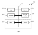
- FIG. 1 shows a schematic diagram of a device for determining a depth image according to various embodiments.
- the device 100 may be implemented by a computer system.
- the edge filter and the processor may also be implemented as modules executing on one or more computer systems.
- the computer system may include a CPU 101 (central processing unit), a processor 103, a memory 105, a network interface 107, input interface/devices 109 and output interface/devices 111. All the components 101, 103, 105, 107, 109, 111 of the computer system 100 may be connected and communicating with each other through a computer bus 113.
- the memory 105 may be used as for storing digital images, edge maps, noise floor adapted depth values, depth scaled values, depth images, threshold values, and intermediate values used and determined according to the method of the embodiments.
- the memory 105 may include more than one memory, such as RAM, ROM, EPROM, hard disk, etc. wherein some of the memories are used for storing data and programs and other memories are used as working memories.
- the memory 105 may be configured to store instructions for determining the depth image for the digital image according to various embodiments.
- the instructions when executed by the CPU 101, may cause the CPU 101 to edge filter the digital image; determine for each edge map region of a plurality of edge map regions an edge map region metric; determine for each edge map region as to whether the respective edge map region metric fulfills a predefined criterion; determine the number of edge map regions for which the respective edge map region metric fulfills the predefined criterion as a first value; determine the number of edge map regions for which the respective edge map region metric does not fulfill the predefined criterion as a second value; and determining the depth image using the first value and the second value.
- the instruction may also cause the CPU 101 to store the digital images, the edge maps, noise floor adapted depth values, depth scaled values, threshold values, intermediate values, and the depth image determined according to the method of the embodiments in the memory 105.
- the processor 103 may be a special purpose processor, in this example, an image processor, for executing the instructions described above.
- the CPU 101 or the processor 103 may be used as the device as described in various embodiments below, and may be connected to an internal network (e.g. a local area network (LAN) or a wide area network (WAN) within an organization) and/or an external network (e.g. the Internet) through the network interface 107.
- an internal network e.g. a local area network (LAN) or a wide area network (WAN) within an organization
- an external network e.g. the Internet
- the input 109 may include a keyboard, a mouse, etc.
- the output 111 may include a display for display the images processed in the embodiments below.
- FIG. 2 shows a flow diagram according to various embodiments.
- the digital image 201 is edge filtered at 210 to determine an edge map 211, wherein the edge map 211 includes a plurality of edge values and each edge value is associated with at least one picture element of the digital image 201.
- the edge map may be used as a sharpness cue in the determination of depth image.
- the digital image 201 may be received via a network interface, or may be stored on a data storage.
- the digital image may be downscaled for one or more times.
- the edge filtering and the subsequent processing on the digital image 201 may be similarly carried out on the downscaled image accordingly.
- each edge value of the edge map may be associated with more than one pixels of the digital image 201.
- the edge filtering 210 may include maximum-minimum filtering, based on the difference between a maximum value and a minimum value within a predefined image region. For example, for each picture element of the digital image 201, a maximum picture element value associated with a picture element in a predefined neighboring region of the respective picture element and a minimum picture element value associated with a picture element in a predefined neighboring region of the respective picture element may be determined, and a difference value between the maximum picture element value and the minimum picture element value may be determined. The edge value associated with the picture element may be determined based on the difference value.
- the edge filtering may use other filtering suitable for detecting the edges, such as maximum filtering and average filtering, for example.
- the edge filtering may include a Canny edge detector, a Sobel operator, or any other suitable edge detection algorithms.
- the digital image may be divided into a plurality of blocks, wherein each block includes a plurality of pixel elements.
- Each determined edge value may be associated with a block of pixel elements.
- the picture element value described in the edge filtering may refer to the intensity value of the picture element in the grayscale image. In another embodiment wherein the digital image 201 is a color image, the picture element value described in the edge filtering may refer to a weighted average value of the color component values of the picture element.
- the edge map 211 may be further processed and evaluated at 220.
- an edge map region metric may be determined.
- a determination may be made as to whether the respective edge region metric fulfills a predefined criterion.
- the number of edge map regions for which the respective edge map region metric fulfills the predefined criterion may be determined as a first value, and the number of edge map regions for which the respective edge map region metric does not fulfill the predefined criterion may be determined as a second value.
- the edge map region metric for each edge map region may include the number of high edge values and the number of low edge values in the respective edge map region.
- the high edge values may represent the edge values higher than a predetermined high threshold
- the low edge values may represent the edge values lower than a predetermined low threshold.
- the predefined criterion may be whether the edge map region metric exceeds a first predefined edge threshold value.
- determining whether the edge map region metric fulfills the predefined criterion may include determining whether the number of high edge values exceeds the first predefined edge threshold value. If the number of high edge values exceeds the first predefined edge threshold value, the associated edge map region may be referred to as a high frequency region, indicating that the edge map region includes sufficient number of high edge values.
- the edge map region metric not fulfilling the predefined criterion may be whether the edge map region metric exceeds a second predefined edge threshold value.
- the second predefined edge threshold value may be different from the first predefined edge threshold value.
- whether the edge map region metric exceeds the second predefined edge threshold value may include whether the number of low edge values in the edge map region metric exceeds the second predefined edge threshold value. If the number of low edge values exceeds the first predefined edge threshold value, the associated edge map region may be referred to as a low frequency region, indicating that the edge map region includes sufficient number of low edge values.
- the edge map evaluation 220 it may be determined as to whether the digital image is a high frequency image or a low frequency image based on the first value and the second value.
- a respective depth scaled value may be determined for each depth value associated with a picture element by reducing the depth value by a first depth scale.
- a respective depth scaled value may be determined for each depth value associated with a picture element by reducing the depth value by a second depth scale. The first depth scale may be smaller than the second depth scale.
- the digital image may be determined to be a high frequency image in case the first value exceeds a first frequency threshold value.
- the first value may represent the number of edge map regions in which the respective number of high edge values exceeds the first predefined edge threshold value, i.e. the number of high frequency regions.
- the digital image may be determined to be a low frequency image in case the second value exceeds a second frequency threshold value.
- the second frequency threshold value may be different from the first frequency threshold value.
- the second value may represent the number of edge map regions in which the respective number of low edge values exceeds the second predefined edge threshold value, i.e. the number of low frequency regions.
- the depth image 231 may be determined at 230.
- the depth image may be determined based on the edge map 211, the first value and the second value via a piece-wise linear mapping function.
- the depth image may be determined based on the edge map 211, the first value and the second value via a S-curve mapping function.
- Other suitable mapping functions may also be used in other embodiments.
- Fig. 3 shows a flow diagram according to another embodiment.
- a digital image 201 is edge filtered at 210 to determine an edge map 211, wherein the edge map 211 includes a plurality of edge values and each edge value is associated with at least one picture element of the digital image 201.
- noise floor and depth scale determination may be made at 220, e.g. to determine the noise floor adaptation values and depth scale for the depth image determination.
- an edge map region metric may be determined for each edge map region of a plurality of edge map regions in the edge map 211.
- a determination may be made as to whether the respective edge region metric fulfills a predefined criterion.
- the number of edge map regions for which the respective edge map region metric fulfills the predefined criterion may be determined as a first value, and the number of edge map regions for which the respective edge map region metric does not fulfill the predefined criterion may be determined as a second value.
- a first noise floor adaptation value or a second noise floor adaptation value may be determined for each picture element at 320, depending on whether the picture element is located in an edge map region for which the respective edge map region metric fulfills the predefined criterion.
- the second noise floor adaptation value may be smaller than the first noise floor adaptation value.
- a first depth scale or a second depth scale may be determined for each picture element. The first depth scale may be smaller than the second depth scale.
- edge noise may be subtracted and the depth value may be scaled in the depth image determination 230 to determine the depth image 231.
- the depth value associated with the picture element may be reduced by the first noise floor adaptation value to determine a noise floor adapted depth value.
- the depth value associated with the picture element may be reduced by the second noise floor adaptation value to determine a noise floor adapted depth value.
- the second noise floor adaptation value may be smaller than the first noise floor adaptation value.
- the depth image 231 may include the respectively determined noise floor adapted depth values.
- a respective depth scaled value may be determined for each depth value associated with a picture element by reducing the depth value by the first depth scale.
- a respective depth scaled value may be determined for each depth value associated with a picture element by reducing the depth value by the second depth scale.
- the first depth scale may be smaller than the second depth scale.
- Fig. 4 shows a flow diagram illustrating the determination of different edge numbers according to an embodiment.
- the edge map 211 as determined at 210 includes a plurality of edge values associated with a plurality of pixels or blocks of pixels. For each edge value or for each block of edge values, it is determined at 410 as to whether the edge value is higher than a predetermined high threshold "edge_Thr_H". In an example, the high threshold "edge_Thr_H" may have a value of 96. If the edge value is higher than the high threshold, the edge value is a high edge value, and the number of high edges is increased by 1.
- edge_Thr_L For each edge value or for each block of edge values, it is determined at 420 as to whether the edge value is smaller than a predetermined low threshold "edge_Thr_L".
- the low threshold "edge_Thr_L” may have a value of 6. If the edge value is lower than the low threshold, the edge value is a low edge value, and the number of low edges is increased by 1.
- the above determination may be made for all edge values of the edge map in a raster scan order, or any other suitable scan order, such that the total number of high edges and the total number of low edges in the edge map 211 may be determined, which represent a global classification of the edge values.
- the total number of high edges and the total number of low edges may be used to determine whether the digital image 210 from which the edge map 211 is determined is a high frequency image (i.e. an image in which the number of high edges is sufficiently high) or a low frequency image (i.e. in image in which the number of low edges is sufficiently high).
- Fig. 5 shows a flow diagram illustrating the determination of different edge regions according to an embodiment.
- the edge map 211 may be divided into NxM (e.g. 9x16) edge map regions, e.g. "region 1", “region 2", ...as shown in Fig. 5 , wherein each edge map region may include a plurality of edge values associated with a plurality of picture elements.
- NxM e.g. 9x16
- each edge map region e.g. "region 1" 213
- each edge map region e.g. "region 1" 213
- the same determination may be made for other edge map regions of the edge map 211. Accordingly, the number of high edges and the number of low edges in each edge map region may be determined according to Fig. 5 , which represents a local classification of the edge values. The number of high edge values and the number of low edge values in the respective edge map region may be determined as the edge map region metric for the respective edge map region.
- the edge map regions and the associated digital image may be classified into various types, which may be taken into account when determining the noise floor and depth scale.
- Fig. 6 shows a flow diagram illustrating the classification of the digital image 210 according to an embodiment.
- the number of high edges and the number of low edges determined for the edge map 211 in Fig. 4 may be compared with a first frequency threshold value and a second frequency threshold value, respectively.
- the digital image 201 associated with the edge map 211 is classified as a high frequency image having a high frequency characteristic.
- the digital image 201 associated with the edge map 211 is classified as both high and low frequency image having both high frequency and low frequency characteristics.
- the digital image 201 associated with the edge map 211 is classified as a low frequency image having a low frequency characteristic. In case the number of low edges in the edge map 211 does not exceed the second frequency threshold value at 630, the digital image 201 associated with the edge map 211 is classified as neither high nor low frequency image having neither high frequency nor low frequency characteristics.
- the determination of low frequency characteristic for the digital image may be independent from the determination of high frequency characteristic.
- each edge map region of the edge map 211 may be classified as to the high frequency or low frequency characteristics.
- Fig. 7 shows a flow diagram illustrating the classification of the edge map regions according to an embodiment.
- the number of high edges and the number of low edges determined for each edge map regions of the edge map 211 in Fig. 5 may be compared with a first edge threshold value and a second edge threshold value, respectively.
- the edge map region 1 it is determined whether the number of high edges in the edge map region 1 exceeds the first edge threshold value. In case the number of high edges exceeds the first edge threshold value, it is determined at 720 whether the number of low edges in the edge map region 1 exceeds the second edge threshold value.
- the second edge threshold value may be different from the first edge threshold value. In case the number of low edges the edge map region 1 does not exceed the second edge threshold value, the edge map region 1 may classified as a high frequency region having a high frequency characteristic. In case the number of low edges in the edge map region 1 exceeds the second edge threshold value at 720, the edge map region 1 is classified as both high and low frequency region having both high frequency and low frequency characteristics.
- the edge map region 1 is classified as a low frequency region having a low frequency characteristic. In case the number of low edges in the edge map region 1 does not exceed the second edge threshold value at 730, the edge map region 1 is classified as neither high nor low frequency region having neither high frequency nor low frequency characteristics.
- the above determination may be made for each edge map regions of the edge map, such that each edge map regions is classified with regard to its high frequency or low frequency characteristics.
- the determination of low frequency characteristic for the edge map regions may be independent from the determination of high frequency characteristic.
- the determination as to whether the digital image is a high or low frequency image is based on the total number of high edges and the total number of low edges in the edge map as determined in Fig. 4 .
- the determination as to whether the digital image is a high or low frequency image may be based on the number of high frequency regions and the number of low frequency regions in the edge map. For example, based on the classification of the edge map regions in the embodiment of Fig. 7 , the number of edge map regions classified as high frequency regions may be counted as a first value, and the number of edge map regions classified as low frequency regions may be countered as a second value. The first value may be compared with the first frequency threshold value, and the second value may be compared with the second frequency threshold value, to determine whether the digital image is a high frequency image or a low frequency image.
- the noise floor and depth scale used in the determination of the depth image may be determined.
- Fig. 8 shows a flow diagram illustrating the determination of depth scale according to an embodiment.
- a first depth scale may be determined.
- a second depth scale may be determined. The first depth scale is lower than the second depth scale.
- the digital image may have intermediate frequency characteristics and may be blurry.
- a lower depth scale may be provided to scale up depth values compared with a digital image which is either a high frequency image or a low frequency image.
- Fig. 9 shows a flow diagram illustrating the determination of noise floor adaptation values according to an embodiment.
- an edge map region the current pixel is in is a low frequency region. In case the current pixel is not located in a low frequency region at 930, a first noise floor adaptation value is determined. In case the current pixel is located in a low frequency region 950, a second noise floor adaptation value may be determined. The first noise floor adaptation value may be higher than the second noise floor adaptation value. Since the effect of the noise on the edge map to the depth image is more harmful in high frequency contents, a higher noise floor adaption value is used in high frequency edge map regions compared with low frequency edge map regions.
- the region including the current pixel in case the region including the current pixel is not a low frequency region, the region may be a high frequency region, or a neither high nor low frequency region as determined in Fig. 7 , for which a higher noise floor adaptation value is used. In case the region including the current pixel is a low frequency region, the region may also be a both high and low frequency region as determined in Fig. 7 , for which a lower noise floor adaptation value is used.
- a higher noise adaptation value may be used for a high frequency region and a both high and low frequency region.
- a lower noise adaptation value may be used for a low frequency region.
- An intermediate noise adaptation value inbetween may be used for a neither high nor low frequency region.
- noise adaptation values and the depth scales as determined in accordance with the embodiments above may be used to adjust the depth values so as to determine a depth image.
- Fig. 10 shows a flow diagram illustrating the noise floor and depth scale adaptation according to an embodiment.
- a noise floor adaptation 1010 is performed to determine noise floor adapted depth values 1011, and a depth scaling 1020 is performed to determine the depth scaled values 1021.
- the depth scaled values 1021 may form the depth values in the determined depth image.
- the similar operations of Fig. 9 are performed. For example, at 910, it is determined whether the edge map region the current pixel is in is a low frequency region. In case the current pixel is not located in a low frequency region at 930, the depth value associated with the current pixel is reduced by a first noise floor adaptation value to determine the noise floor adapted depth value 1011. In case the current pixel is located in a low frequency region 950, the depth value associated with the current pixel is reduced by a second noise floor adaptation value to determine the noise floor adapted depth value 1011. The first noise floor adaptation value may be higher than the second noise floor adaptation value.
- the similar operations of Fig. 8 are performed. For example, at 810 it is determined whether the digital image is neither a high frequency image nor a low frequency image. In case the digital image is neither a high frequency image nor a low frequency image at 830, the depth value associated with the current pixel is reduced by a first depth scale to determine a new depth scaled value 1021. In case the digital image is either a high frequency image or a low frequency image, or a both high and low frequency image at 850, the depth value associated with the current pixel is reduced by a second depth scale to determine a new depth scaled value 1021. The first depth scale is lower than the second depth scale.
- the finally determined depth image may include depth values adapted by noise floor adaptation values and scaled by the depth scales, which may be determined by a mapping from the edge map.
- the depth values of the depth image may be determined using the edge values of the edge map via a piece-wise linear mapping function.
- the x-axis and y-axis represent edge values and depth values, respectively.
- the edge lower bound value 1111 represents the noise floor value, which may be determined in accordance with the above embodiments. Edge values below the edge lower bound value 1111 may be assigned with the highest depth value, as shown in Fig. 11 .
- the depth range 1121 defines how much depth variation may be obtained based on the edge value variations.
- the tangent of the mapping function, Theta 1131 represents the depth scale as determined in accordance with the above embodiments.
- a low depth scale value may push regions of the image more to the background, whereas a high depth scale value may push regions of the image more to the foreground.
- a range of edge values below the maximum edge value 1113 may be mapped to the same depth value, e.g. the lowest depth value representing the foreground object.
- the depth image may be determined by mapping the edge map using other suitable mapping functions. For example, when a look-up table is provided, a S-curve mapping function may be used, wherein the noise floor may also be used to set the starting point of the S-curve and the depth scale factor may be used for blending coefficient
- the embodiments above provide a method and a device for determining a depth image indicating the relative depth of the objects in the digital image, i.e., which objects are in the front and which objects are at the back, using a 2D digital image (i.e. a single viewpoint image). Based on the determined depth image, 2D images or videos may be converted to 3D images or videos.
- the method and the device of the various embodiments provide a depth image with more accuracy, by adjusting noise elimination level and depth scale level based on the high or low frequency characteristics of the image and its edge map regions.
- FIG. 12 shows an imaging system according to an embodiment.
- the imaging system 1200 receives an image 1201, which may be a digital image 201 as described above.
- the imaging system 1200 includes an image processing device 1210 for determining a depth image for each image 1201 in accordance with the various embodiments above.
- the determined depth image 1211 is transmitted to an image render 1220.
- the image render 1220 may receive the image 1201 and the depth map 1211 and render the image 1201 for 3D display.
- the imaging system 1200 may be embodied in a 3D TV or a computer, for example.
- the method and the device for determining the depth image in the above embodiments provide accurate depth values, by subtracting out edge noise effects and scaling edge values based on the high or low frequency characteristics of the image and its edge map regions.
- the method and the device are based on the 2D images or videos, which enables displaying of 2D content in a 3D display and may also be used in any other areas in which the depth information or the information about the location of the objects in a scene is required.
Landscapes
- Engineering & Computer Science (AREA)
- Computer Vision & Pattern Recognition (AREA)
- Physics & Mathematics (AREA)
- General Physics & Mathematics (AREA)
- Theoretical Computer Science (AREA)
- Image Processing (AREA)
- Image Analysis (AREA)
- Compression Or Coding Systems Of Tv Signals (AREA)
Claims (10)
- Verfahren zum Bestimmen einer Bildtiefe (231) für ein digitales Bild (201), welches eine Vielzahl von Bildelementen enthält, das Verfahren mit• Kantenfiltern (201) des digitalen Bilds, um ein Kantenbild oder eine Kantenkarte (edge map) zu bestimmen, wobei die Kantenkarte (211) eine Vielzahl von Kantenwerten aufweist und jeder Kartenwert zumindest einem Bildelement zugeordnet ist;• Bestimmen (220) einer metrischen Kantenkarten-Region für jede Kantenkarte-Region einer Vielzahl von Kantenkarten-Regionen, wobei die metrische Kantenkarten-Region (edge map region metric) für jede Kantenkarten-Region die Anzahl von hohen Kantenwerten und die Anzahl von niedrigen Kantenwerten in der jeweiligen Kantenkarten-Region beinhaltet;• Bestimmen - für jede Kantenkarten-Region - ,ob die jeweilige metrische Kantenkarten-Region ein vorbestimmtes Kriterium erfüllt, wobei das vorbestimmte Kriterium erfüllt ist, wenn die Anzahl der hohen Kantenwerte einen ersten vorgegebenen Schwellenwert überschreitet, und das vorbestimmte Kriterium nicht erfüllt ist, wenn die Anzahl von niedrigen Kantenwerten einen zweiten vorgegebenen Schwellenwert überschreitet;• Bestimmen der Anzahl von Kantenkarten-Regionen für welche die jeweilige metrische Kantenkarten-Region das vorbestimmte Kriterium als einen ersten Wert erfüllt;• Bestimmen der Anzahl von Kantenkarten-Regionen für welche die jeweilige metrische Kantenkarten-Region das vorbestimmte Kriterium als einen zweiten Wert nicht erfüllt; und• Bestimmen (230) der Bildtiefe unter Verwendung des ersten Wertes und des zweiten Wertes, wobei die Tiefenwerte des Tiefenbilds (depth image) bestimmt werden, unter Verwendung der Kantenwerte der Kantenkarte über eine stückweise lineare Mapping-Funktion.
- Verfahren nach Anspruch 1, wobei das Bestimmen der Bildtiefe umfasst• Bestimmen - für jedes Bildelement, welches einem Tiefenwert zugeordnet ist - ,ob das Bildelement in einer Kantenkarten-Region liegt, für welche die jeweilige metrische Kantenkarten-Region das vorgegebene Kriterium erfüllt;• falls das Bildelement in einer Kantenkarten-Region liegt, für die die jeweilige metrische Kantenkarten-Region das vorbestimmte Kriterium erfüllt, Reduzieren des zugeordneten Tiefenwerts, um eine erste Grundrausch-Anpassung dem Wert nach, zur Bestimmung eines im Grundrauschen angepassten Tiefenwertes;• wenn das Bildelement in einer Kantenkarten-Region liegt, für welche die jeweilige metrische Kantenkarten-Region das vorbestimmte oder vorgegebene Kriterium nicht erfüllt, wird der zugeordnete Tiefenwert um einen zweiten Grundrausch-Anpassungswert reduziert, um einen im Grundrauschen angepassten Tiefenwert zu erhalten oder zu bestimmen, wobei der zweite Grundrausch-Anpassungswert kleiner ist als der erste Grundrausch-Anpassungswert;• wobei das Tiefenbild die jeweils bestimmten, im Grundrauschen angepassten Tiefenwerte aufweist oder beinhaltet.
- Verfahren nach einem der Ansprüche 1 oder 2, wobei das Bestimmen des Tiefenbilds umfasst• Bestimmen, ob das digitale Bild ein Hochfrequenz-Bild ist, oder ein NiederfrequenzBild, gestützt auf den ersten Wert und den zweiten Wert;• falls das digitale Bild weder ein Hochfrequenz-Bild noch ein Niederfrequenz-Bild ist, Bestimmen - für jeden Tiefenwert, der einem Bildelement zugeordnet ist - eines jeweils tiefenskalierten Werts durch Reduzieren des Tiefenwerts um eine erste Tiefenskala (depth scale); und• falls das digitale Bild entweder ein Hochfrequenz-Bild oder ein Niederfrequenz-Bild ist, Bestimmen - für jeden Tiefenwert, der einem Bildelement zugeordnet ist - eines jeweiligen tiefenskalierten Werts (depth scaled value) durch Reduzieren des Tiefenwerts mit oder um eine zweite Tiefenskala oder einen zweiten Tiefenwert (depth scale), wobei die erste Tiefenskala kleiner ist als die zweite Tiefenskala.
- Verfahren nach Anspruch 1, wobei der erste vorbestimmte Schwellenwert sich von dem zweiten vorbestimmten Schwellenwert unterscheidet.
- Verfahren nach einem der Ansprüche 1 bis 4, wobei das Bestimmen, ob das Bild ein Hochfrequenz-Bild oder ein Niederfrequenz-Bild ist, umfasst• Bestimmen, dass das digitale Bild ein Hochfrequenz-Bild ist, wenn der erste Wert einen ersten Frequenz-Schwellenwert überschreitet;• Bestimmen, dass das digitale Bild ein Niederfrequenz-Bild ist, wenn der zweite Wert einen zweiten Frequenz-Schwellenwert überschreitet, wobei der zweite Frequenz-Schwellenwert sich von dem ersten Frequenz-Schwellenwert unterscheidet.
- Anordnung (100, 1210) zum Bestimmen eines Tiefenbildes (231) für ein Digitalbild (201), welches eine Vielzahl von Bildelementen umfasst, wobei die Einrichtung aufweist:einen Kantenfilter, ausgebildet zum Filtern (210) des Digitalbildes zur Bestimmung einer Kantenkarte, wobei die Kantenkarte (211) eine Vielzahl von Kantenwerten umfasst, wobei jeder Kantenwert zumindest einem Bildelement zugeordnet ist; einen Prozessor (103), ausgebildet zum• Bestimmen (220) - für jede Kantenkarten-Region einer Mehrzahl oder Vielzahl von Kantenkarten-Regionen - einer metrischen Kantenkarten-Region, wobei die metrische Kantenkarten-Region für jede Kantenkarten-Region die Zahl der hohen Kantenwerte und die Zahl der niedrigen Kantenwerte in der jeweiligen Kantenkarten-Region aufweist oder beinhaltet;• Bestimmen - für jede Kantenkarten-Region -,ob die jeweilige metrische Kantenkarten-Region ein vorbestimmtes Kriterium erfüllt, wobei das vorbestimmte Kriterium erfüllt ist, wenn die Anzahl der hohen Kantenwerte einen ersten vorgegebenen Schwellenwert überschreitet und das vorgegebene zweite Kriterium nicht erfüllt ist, wenn die Anzahl der niedrigen Kantenwerte einen zweiten vorbestimmten Schwellenwert überschreitet;• Bestimmen der Anzahl von Kantenkarten-Regionen für die die jeweilige metrische Kantenkarten-Region das vorbestimmte Kriterium als einen ersten Wert erfüllt;• Bestimmen der Zahl der Kantenkarten-Regionen für die die jeweilige metrische Kantenkarten-Region das vorgegebene Kriterium als einen zweiten Wert nicht erfüllt;• Bestimmen der Bildtiefe (230) unter Verwendung des ersten Wertes und des zweiten Wertes, wobei die Tiefenwerte des Tiefenbildes unter Verwendung der Kantenwerte der Kantenkarte über eine stückweise lineare Mapping-Funktion bestimmt werden oder bestimmbar sind.
- Einrichtung nach Anspruch 6, wobei der Prozessor ausgebildet (konfiguriert) ist, das Tiefenbild so zu bestimmen, dass sie (NB. die Ausbildung) beinhaltet• Bestimmen - für jedes Bildelement, welches einem Tiefenwert zugeordnet ist - ,ob das Bildelement in einer Kantenkarten-Region liegt, für welche die jeweilige metrische Kantenkarten-Region das vorgegebene Kriterium erfüllt;• falls das Bildelement in einer Kantenkarten-Region liegt, für die die jeweilige metrische Kantenkarten-Region das vorbestimmte Kriterium erfüllt, Reduzieren des zugeordneten Tiefenbilds, um eine erste Grundrausch-Anpassung dem Wert nach, zur Bestimmung eines im Grundrauschen angepassten Tiefenwerts;• wenn das Bildelement in einer Kantenkarten-Region liegt, für welche die jeweilige metrische Kantenkarten-Region das vorbestimmte oder vorgegebene Kriterium nicht erfüllt, wird der zugeordnete Tiefenwert um einen zweiten GrundrauschAnpassungswert reduziert, um einen im Grundrauschen angepassten Tiefenwert zu erhalten oder zu bestimmen, wobei der zweite Grundrausch-Anpassungswert kleiner ist als der erste Grundrausch-Anpassungswert;• wobei das Tiefenbild die jeweils bestimmten, im Grundrauschen angepassten Tiefenwerte aufweist oder beinhaltet.
- Einrichtung nach einem der Ansprüche 6 oder 7, wobei der Prozessor ausgebildet (konfiguriert) ist, das Tiefenbild so zu bestimmen, dass sie (die Ausbildung oder Konfiguration) umfasst• Bestimmen, ob das digitale Bild ein Hochfrequenz-Bild ist, oder ein NiederfrequenzBild, gestützt auf den ersten Wert und den zweiten Wert;• falls das digitale Bild weder ein Hochfrequenz-Bild noch ein Niederfrequenz-Bild ist, Bestimmen - für jeden Tiefenwert, der einem Bildelement zugeordnet ist - eines jeweils tiefenskalierten Werts durch Reduzieren des Tiefenwerts um eine erste Tiefenskala (depth scale); und• falls das digitale Bild entweder ein Hochfrequenz-Bild oder ein Niederfrequenz-Bild ist, Bestimmen - für jeden Tiefenwert, der einem Bildelement zugeordnet ist - eines jeweiligen tiefenskalierten Werts (depth scaled value) durch Reduzieren des Tiefenwerts mit oder um eine zweite Tiefenskala oder einen zweiten Tiefenwert (depth scale), wobei die erste Tiefenskala kleiner ist als die zweite Tiefenskala.
- Einrichtung nach Anspruch 6, wobei der erste vorgegebene Schwellenwert sich von dem zweiten vorgegebenen Schwellenwert unterscheidet.
- Einrichtung nach einem der Ansprüche 6 bis 9, wobei der Prozessor so ausgebildet oder konfiguriert ist, dass er bestimmt, ob das Digitalbild ein Hochfrequenz-Bild oder ein Niederfrequenz-Bild ist, wobei sie (die Ausbildung oder Konfiguration) umfasst• Bestimmen, dass das Digitalbild ein Hochfrequenz-Bild ist, wenn der erste Wert einen ersten Frequenz-Schwellenwert überschreitet;• Bestimmen, dass das digitale Bild ein Niederfrequenz-Bild ist, wenn der zweite Wert einen zweiten Frequenz-Schwellenwert überschreitet, wobei der zweite Frequenz-Schwellenwert sich von dem ersten Frequenz-Schwellenwert unterscheidet.
Priority Applications (2)
| Application Number | Priority Date | Filing Date | Title |
|---|---|---|---|
| ES12173823.1T ES2533051T3 (es) | 2012-06-27 | 2012-06-27 | Procedimiento y dispositivo para determinar una imagen de profundidad |
| EP12173823.1A EP2680224B1 (de) | 2012-06-27 | 2012-06-27 | Verfahren und Vorrichtung zur Bestimmung eines Tiefenbildes |
Applications Claiming Priority (1)
| Application Number | Priority Date | Filing Date | Title |
|---|---|---|---|
| EP12173823.1A EP2680224B1 (de) | 2012-06-27 | 2012-06-27 | Verfahren und Vorrichtung zur Bestimmung eines Tiefenbildes |
Publications (2)
| Publication Number | Publication Date |
|---|---|
| EP2680224A1 EP2680224A1 (de) | 2014-01-01 |
| EP2680224B1 true EP2680224B1 (de) | 2015-01-07 |
Family
ID=46319646
Family Applications (1)
| Application Number | Title | Priority Date | Filing Date |
|---|---|---|---|
| EP12173823.1A Active EP2680224B1 (de) | 2012-06-27 | 2012-06-27 | Verfahren und Vorrichtung zur Bestimmung eines Tiefenbildes |
Country Status (2)
| Country | Link |
|---|---|
| EP (1) | EP2680224B1 (de) |
| ES (1) | ES2533051T3 (de) |
Cited By (1)
| Publication number | Priority date | Publication date | Assignee | Title |
|---|---|---|---|---|
| US10685455B2 (en) * | 2018-05-02 | 2020-06-16 | Stable Auto Corporation | Method and system for automated vehicle charging |
Families Citing this family (3)
| Publication number | Priority date | Publication date | Assignee | Title |
|---|---|---|---|---|
| CN106055331B (zh) * | 2016-05-31 | 2019-12-03 | 福建天晴数码有限公司 | 模型边界生成方法和装置 |
| CN112150529B (zh) * | 2019-06-28 | 2023-09-01 | 北京地平线机器人技术研发有限公司 | 一种图像特征点的深度信息确定方法及装置 |
| CN116489333A (zh) * | 2023-04-07 | 2023-07-25 | 南通大学 | 一种面向深度图编码单元划分的边缘分类模型构建方法 |
Family Cites Families (2)
| Publication number | Priority date | Publication date | Assignee | Title |
|---|---|---|---|---|
| US6584219B1 (en) * | 1997-09-18 | 2003-06-24 | Sanyo Electric Co., Ltd. | 2D/3D image conversion system |
| KR101370356B1 (ko) * | 2005-12-02 | 2014-03-05 | 코닌클리케 필립스 엔.브이. | 스테레오스코픽 화상 디스플레이 방법 및 장치, 2d 화상데이터 입력으로부터 3d 화상 데이터를 생성하는 방법,그리고 2d 화상 데이터 입력으로부터 3d 화상 데이터를생성하는 장치 |
-
2012
- 2012-06-27 ES ES12173823.1T patent/ES2533051T3/es active Active
- 2012-06-27 EP EP12173823.1A patent/EP2680224B1/de active Active
Cited By (1)
| Publication number | Priority date | Publication date | Assignee | Title |
|---|---|---|---|---|
| US10685455B2 (en) * | 2018-05-02 | 2020-06-16 | Stable Auto Corporation | Method and system for automated vehicle charging |
Also Published As
| Publication number | Publication date |
|---|---|
| EP2680224A1 (de) | 2014-01-01 |
| ES2533051T3 (es) | 2015-04-07 |
Similar Documents
| Publication | Publication Date | Title |
|---|---|---|
| US8447141B2 (en) | Method and device for generating a depth map | |
| JP5010729B2 (ja) | ビデオ変換システムのためのデプスマップを生成する方法およびそのシステム | |
| KR101452172B1 (ko) | 깊이―관련 정보를 처리하기 위한 방법, 장치 및 시스템 | |
| EP2774124B1 (de) | Tiefenkartenerzeugung für ein eingangsbild mit einer annähernden beispieltiefe, assoziiert mit einem ähnlichen beispielbild | |
| US9137512B2 (en) | Method and apparatus for estimating depth, and method and apparatus for converting 2D video to 3D video | |
| US9525858B2 (en) | Depth or disparity map upscaling | |
| KR102464523B1 (ko) | 이미지 속성 맵을 프로세싱하기 위한 방법 및 장치 | |
| EP2706504A2 (de) | Vorrichtung, Verfahren und Computerprogramm zur Bildverarbeitung | |
| WO2013109252A1 (en) | Generating an image for another view | |
| WO2013158784A1 (en) | Systems and methods for improving overall quality of three-dimensional content by altering parallax budget or compensating for moving objects | |
| US8982187B2 (en) | System and method of rendering stereoscopic images | |
| US8369609B2 (en) | Reduced-complexity disparity map estimation | |
| EP2680224B1 (de) | Verfahren und Vorrichtung zur Bestimmung eines Tiefenbildes | |
| TWI678098B (zh) | 三維影像之視差的處理 | |
| Ceulemans et al. | Efficient MRF-based disocclusion inpainting in multiview video | |
| TWI540536B (zh) | 處理三維場景之深度資料 | |
| US20120170841A1 (en) | Image processing apparatus and method | |
| US9787980B2 (en) | Auxiliary information map upsampling | |
| EP2557537B1 (de) | Verfahren und Bildverarbeitungsvorrichtung zur Verarbeitung von Disparität | |
| EP2677496B1 (de) | Verfahren und Vorrichtung zum Bestimmung eines Tiefenbildes | |
| EP2657909B1 (de) | Verfahren und Bildverarbeitungsvorrichtung zur Bestimmung von Disparität | |
| Fatima et al. | Quality assessment of 3D synthesized images based on structural and textural distortion | |
| JP6056459B2 (ja) | 奥行き推定データ生成装置、擬似立体画像生成装置、奥行き推定データ生成方法及び奥行き推定データ生成プログラム | |
| US9137519B1 (en) | Generation of a stereo video from a mono video | |
| Köppel | Filling disocclusions in extrapolated virtual views using advanced texture synthesis methods |
Legal Events
| Date | Code | Title | Description |
|---|---|---|---|
| PUAI | Public reference made under article 153(3) epc to a published international application that has entered the european phase |
Free format text: ORIGINAL CODE: 0009012 |
|
| AK | Designated contracting states |
Kind code of ref document: A1 Designated state(s): AL AT BE BG CH CY CZ DE DK EE ES FI FR GB GR HR HU IE IS IT LI LT LU LV MC MK MT NL NO PL PT RO RS SE SI SK SM TR |
|
| AX | Request for extension of the european patent |
Extension state: BA ME |
|
| 17P | Request for examination filed |
Effective date: 20140630 |
|
| GRAP | Despatch of communication of intention to grant a patent |
Free format text: ORIGINAL CODE: EPIDOSNIGR1 |
|
| INTG | Intention to grant announced |
Effective date: 20140814 |
|
| GRAS | Grant fee paid |
Free format text: ORIGINAL CODE: EPIDOSNIGR3 |
|
| GRAA | (expected) grant |
Free format text: ORIGINAL CODE: 0009210 |
|
| AK | Designated contracting states |
Kind code of ref document: B1 Designated state(s): AL AT BE BG CH CY CZ DE DK EE ES FI FR GB GR HR HU IE IS IT LI LT LU LV MC MK MT NL NO PL PT RO RS SE SI SK SM TR |
|
| REG | Reference to a national code |
Ref country code: GB Ref legal event code: FG4D |
|
| REG | Reference to a national code |
Ref country code: CH Ref legal event code: EP |
|
| REG | Reference to a national code |
Ref country code: IE Ref legal event code: FG4D |
|
| REG | Reference to a national code |
Ref country code: AT Ref legal event code: REF Ref document number: 706193 Country of ref document: AT Kind code of ref document: T Effective date: 20150215 |
|
| REG | Reference to a national code |
Ref country code: DE Ref legal event code: R096 Ref document number: 602012004724 Country of ref document: DE Effective date: 20150226 |
|
| REG | Reference to a national code |
Ref country code: FR Ref legal event code: PLFP Year of fee payment: 4 |
|
| REG | Reference to a national code |
Ref country code: ES Ref legal event code: FG2A Ref document number: 2533051 Country of ref document: ES Kind code of ref document: T3 Effective date: 20150407 |
|
| REG | Reference to a national code |
Ref country code: NL Ref legal event code: VDEP Effective date: 20150107 |
|
| REG | Reference to a national code |
Ref country code: AT Ref legal event code: MK05 Ref document number: 706193 Country of ref document: AT Kind code of ref document: T Effective date: 20150107 |
|
| REG | Reference to a national code |
Ref country code: LT Ref legal event code: MG4D |
|
| PG25 | Lapsed in a contracting state [announced via postgrant information from national office to epo] |
Ref country code: FI Free format text: LAPSE BECAUSE OF FAILURE TO SUBMIT A TRANSLATION OF THE DESCRIPTION OR TO PAY THE FEE WITHIN THE PRESCRIBED TIME-LIMIT Effective date: 20150107 Ref country code: HR Free format text: LAPSE BECAUSE OF FAILURE TO SUBMIT A TRANSLATION OF THE DESCRIPTION OR TO PAY THE FEE WITHIN THE PRESCRIBED TIME-LIMIT Effective date: 20150107 Ref country code: SE Free format text: LAPSE BECAUSE OF FAILURE TO SUBMIT A TRANSLATION OF THE DESCRIPTION OR TO PAY THE FEE WITHIN THE PRESCRIBED TIME-LIMIT Effective date: 20150107 Ref country code: BG Free format text: LAPSE BECAUSE OF FAILURE TO SUBMIT A TRANSLATION OF THE DESCRIPTION OR TO PAY THE FEE WITHIN THE PRESCRIBED TIME-LIMIT Effective date: 20150407 Ref country code: LT Free format text: LAPSE BECAUSE OF FAILURE TO SUBMIT A TRANSLATION OF THE DESCRIPTION OR TO PAY THE FEE WITHIN THE PRESCRIBED TIME-LIMIT Effective date: 20150107 Ref country code: NO Free format text: LAPSE BECAUSE OF FAILURE TO SUBMIT A TRANSLATION OF THE DESCRIPTION OR TO PAY THE FEE WITHIN THE PRESCRIBED TIME-LIMIT Effective date: 20150407 |
|
| PG25 | Lapsed in a contracting state [announced via postgrant information from national office to epo] |
Ref country code: PL Free format text: LAPSE BECAUSE OF FAILURE TO SUBMIT A TRANSLATION OF THE DESCRIPTION OR TO PAY THE FEE WITHIN THE PRESCRIBED TIME-LIMIT Effective date: 20150107 Ref country code: NL Free format text: LAPSE BECAUSE OF FAILURE TO SUBMIT A TRANSLATION OF THE DESCRIPTION OR TO PAY THE FEE WITHIN THE PRESCRIBED TIME-LIMIT Effective date: 20150107 Ref country code: GR Free format text: LAPSE BECAUSE OF FAILURE TO SUBMIT A TRANSLATION OF THE DESCRIPTION OR TO PAY THE FEE WITHIN THE PRESCRIBED TIME-LIMIT Effective date: 20150408 Ref country code: LV Free format text: LAPSE BECAUSE OF FAILURE TO SUBMIT A TRANSLATION OF THE DESCRIPTION OR TO PAY THE FEE WITHIN THE PRESCRIBED TIME-LIMIT Effective date: 20150107 Ref country code: IS Free format text: LAPSE BECAUSE OF FAILURE TO SUBMIT A TRANSLATION OF THE DESCRIPTION OR TO PAY THE FEE WITHIN THE PRESCRIBED TIME-LIMIT Effective date: 20150507 Ref country code: AT Free format text: LAPSE BECAUSE OF FAILURE TO SUBMIT A TRANSLATION OF THE DESCRIPTION OR TO PAY THE FEE WITHIN THE PRESCRIBED TIME-LIMIT Effective date: 20150107 Ref country code: RS Free format text: LAPSE BECAUSE OF FAILURE TO SUBMIT A TRANSLATION OF THE DESCRIPTION OR TO PAY THE FEE WITHIN THE PRESCRIBED TIME-LIMIT Effective date: 20150107 |
|
| REG | Reference to a national code |
Ref country code: DE Ref legal event code: R097 Ref document number: 602012004724 Country of ref document: DE |
|
| PG25 | Lapsed in a contracting state [announced via postgrant information from national office to epo] |
Ref country code: EE Free format text: LAPSE BECAUSE OF FAILURE TO SUBMIT A TRANSLATION OF THE DESCRIPTION OR TO PAY THE FEE WITHIN THE PRESCRIBED TIME-LIMIT Effective date: 20150107 Ref country code: DK Free format text: LAPSE BECAUSE OF FAILURE TO SUBMIT A TRANSLATION OF THE DESCRIPTION OR TO PAY THE FEE WITHIN THE PRESCRIBED TIME-LIMIT Effective date: 20150107 Ref country code: RO Free format text: LAPSE BECAUSE OF FAILURE TO SUBMIT A TRANSLATION OF THE DESCRIPTION OR TO PAY THE FEE WITHIN THE PRESCRIBED TIME-LIMIT Effective date: 20150107 Ref country code: SK Free format text: LAPSE BECAUSE OF FAILURE TO SUBMIT A TRANSLATION OF THE DESCRIPTION OR TO PAY THE FEE WITHIN THE PRESCRIBED TIME-LIMIT Effective date: 20150107 Ref country code: CZ Free format text: LAPSE BECAUSE OF FAILURE TO SUBMIT A TRANSLATION OF THE DESCRIPTION OR TO PAY THE FEE WITHIN THE PRESCRIBED TIME-LIMIT Effective date: 20150107 |
|
| PLBE | No opposition filed within time limit |
Free format text: ORIGINAL CODE: 0009261 |
|
| STAA | Information on the status of an ep patent application or granted ep patent |
Free format text: STATUS: NO OPPOSITION FILED WITHIN TIME LIMIT |
|
| 26N | No opposition filed |
Effective date: 20151008 |
|
| PG25 | Lapsed in a contracting state [announced via postgrant information from national office to epo] |
Ref country code: MC Free format text: LAPSE BECAUSE OF FAILURE TO SUBMIT A TRANSLATION OF THE DESCRIPTION OR TO PAY THE FEE WITHIN THE PRESCRIBED TIME-LIMIT Effective date: 20150107 |
|
| REG | Reference to a national code |
Ref country code: CH Ref legal event code: PL |
|
| PG25 | Lapsed in a contracting state [announced via postgrant information from national office to epo] |
Ref country code: LU Free format text: LAPSE BECAUSE OF FAILURE TO SUBMIT A TRANSLATION OF THE DESCRIPTION OR TO PAY THE FEE WITHIN THE PRESCRIBED TIME-LIMIT Effective date: 20150627 Ref country code: SI Free format text: LAPSE BECAUSE OF FAILURE TO SUBMIT A TRANSLATION OF THE DESCRIPTION OR TO PAY THE FEE WITHIN THE PRESCRIBED TIME-LIMIT Effective date: 20150107 |
|
| REG | Reference to a national code |
Ref country code: IE Ref legal event code: MM4A |
|
| REG | Reference to a national code |
Ref country code: FR Ref legal event code: PLFP Year of fee payment: 5 |
|
| PG25 | Lapsed in a contracting state [announced via postgrant information from national office to epo] |
Ref country code: IE Free format text: LAPSE BECAUSE OF NON-PAYMENT OF DUE FEES Effective date: 20150627 Ref country code: LI Free format text: LAPSE BECAUSE OF NON-PAYMENT OF DUE FEES Effective date: 20150630 Ref country code: CH Free format text: LAPSE BECAUSE OF NON-PAYMENT OF DUE FEES Effective date: 20150630 |
|
| PG25 | Lapsed in a contracting state [announced via postgrant information from national office to epo] |
Ref country code: BE Free format text: LAPSE BECAUSE OF FAILURE TO SUBMIT A TRANSLATION OF THE DESCRIPTION OR TO PAY THE FEE WITHIN THE PRESCRIBED TIME-LIMIT Effective date: 20150107 |
|
| PG25 | Lapsed in a contracting state [announced via postgrant information from national office to epo] |
Ref country code: MT Free format text: LAPSE BECAUSE OF FAILURE TO SUBMIT A TRANSLATION OF THE DESCRIPTION OR TO PAY THE FEE WITHIN THE PRESCRIBED TIME-LIMIT Effective date: 20150107 |
|
| REG | Reference to a national code |
Ref country code: FR Ref legal event code: PLFP Year of fee payment: 6 |
|
| PG25 | Lapsed in a contracting state [announced via postgrant information from national office to epo] |
Ref country code: SM Free format text: LAPSE BECAUSE OF FAILURE TO SUBMIT A TRANSLATION OF THE DESCRIPTION OR TO PAY THE FEE WITHIN THE PRESCRIBED TIME-LIMIT Effective date: 20150107 Ref country code: HU Free format text: LAPSE BECAUSE OF FAILURE TO SUBMIT A TRANSLATION OF THE DESCRIPTION OR TO PAY THE FEE WITHIN THE PRESCRIBED TIME-LIMIT; INVALID AB INITIO Effective date: 20120627 |
|
| PG25 | Lapsed in a contracting state [announced via postgrant information from national office to epo] |
Ref country code: CY Free format text: LAPSE BECAUSE OF FAILURE TO SUBMIT A TRANSLATION OF THE DESCRIPTION OR TO PAY THE FEE WITHIN THE PRESCRIBED TIME-LIMIT Effective date: 20150107 |
|
| REG | Reference to a national code |
Ref country code: FR Ref legal event code: PLFP Year of fee payment: 7 |
|
| PG25 | Lapsed in a contracting state [announced via postgrant information from national office to epo] |
Ref country code: PT Free format text: LAPSE BECAUSE OF FAILURE TO SUBMIT A TRANSLATION OF THE DESCRIPTION OR TO PAY THE FEE WITHIN THE PRESCRIBED TIME-LIMIT Effective date: 20150107 Ref country code: MK Free format text: LAPSE BECAUSE OF FAILURE TO SUBMIT A TRANSLATION OF THE DESCRIPTION OR TO PAY THE FEE WITHIN THE PRESCRIBED TIME-LIMIT Effective date: 20150107 |
|
| PG25 | Lapsed in a contracting state [announced via postgrant information from national office to epo] |
Ref country code: AL Free format text: LAPSE BECAUSE OF FAILURE TO SUBMIT A TRANSLATION OF THE DESCRIPTION OR TO PAY THE FEE WITHIN THE PRESCRIBED TIME-LIMIT Effective date: 20150107 |
|
| REG | Reference to a national code |
Ref country code: DE Ref legal event code: R082 Ref document number: 602012004724 Country of ref document: DE Representative=s name: LEONHARD, REIMUND, DIPL.-ING., DE |
|
| PGFP | Annual fee paid to national office [announced via postgrant information from national office to epo] |
Ref country code: FR Payment date: 20230627 Year of fee payment: 12 Ref country code: DE Payment date: 20230620 Year of fee payment: 12 |
|
| PGFP | Annual fee paid to national office [announced via postgrant information from national office to epo] |
Ref country code: TR Payment date: 20230620 Year of fee payment: 12 |
|
| PGFP | Annual fee paid to national office [announced via postgrant information from national office to epo] |
Ref country code: IT Payment date: 20230623 Year of fee payment: 12 Ref country code: GB Payment date: 20230622 Year of fee payment: 12 Ref country code: ES Payment date: 20230829 Year of fee payment: 12 |