EP2680093A2 - System for enhancing power tools - Google Patents
System for enhancing power tools Download PDFInfo
- Publication number
- EP2680093A2 EP2680093A2 EP13173747.0A EP13173747A EP2680093A2 EP 2680093 A2 EP2680093 A2 EP 2680093A2 EP 13173747 A EP13173747 A EP 13173747A EP 2680093 A2 EP2680093 A2 EP 2680093A2
- Authority
- EP
- European Patent Office
- Prior art keywords
- power tool
- battery pack
- computing device
- tool battery
- power
- Prior art date
- Legal status (The legal status is an assumption and is not a legal conclusion. Google has not performed a legal analysis and makes no representation as to the accuracy of the status listed.)
- Withdrawn
Links
Images

Classifications
-
- G—PHYSICS
- G05—CONTROLLING; REGULATING
- G05B—CONTROL OR REGULATING SYSTEMS IN GENERAL; FUNCTIONAL ELEMENTS OF SUCH SYSTEMS; MONITORING OR TESTING ARRANGEMENTS FOR SUCH SYSTEMS OR ELEMENTS
- G05B15/00—Systems controlled by a computer
- G05B15/02—Systems controlled by a computer electric
-
- B—PERFORMING OPERATIONS; TRANSPORTING
- B25—HAND TOOLS; PORTABLE POWER-DRIVEN TOOLS; MANIPULATORS
- B25F—COMBINATION OR MULTI-PURPOSE TOOLS NOT OTHERWISE PROVIDED FOR; DETAILS OR COMPONENTS OF PORTABLE POWER-DRIVEN TOOLS NOT PARTICULARLY RELATED TO THE OPERATIONS PERFORMED AND NOT OTHERWISE PROVIDED FOR
- B25F5/00—Details or components of portable power-driven tools not particularly related to the operations performed and not otherwise provided for
-
- G—PHYSICS
- G05—CONTROLLING; REGULATING
- G05B—CONTROL OR REGULATING SYSTEMS IN GENERAL; FUNCTIONAL ELEMENTS OF SUCH SYSTEMS; MONITORING OR TESTING ARRANGEMENTS FOR SUCH SYSTEMS OR ELEMENTS
- G05B19/00—Program-control systems
- G05B19/02—Program-control systems electric
- G05B19/04—Program control other than numerical control, i.e. in sequence controllers or logic controllers
- G05B19/048—Monitoring; Safety
-
- G—PHYSICS
- G05—CONTROLLING; REGULATING
- G05B—CONTROL OR REGULATING SYSTEMS IN GENERAL; FUNCTIONAL ELEMENTS OF SUCH SYSTEMS; MONITORING OR TESTING ARRANGEMENTS FOR SUCH SYSTEMS OR ELEMENTS
- G05B19/00—Program-control systems
- G05B19/02—Program-control systems electric
- G05B19/18—Numerical control [NC], i.e. automatically operating machines, in particular machine tools, e.g. in a manufacturing environment, so as to execute positioning, movement or co-ordinated operations by means of program data in numerical form
- G05B19/409—Numerical control [NC], i.e. automatically operating machines, in particular machine tools, e.g. in a manufacturing environment, so as to execute positioning, movement or co-ordinated operations by means of program data in numerical form characterised by using manual data input [MDI] or by using control panel, e.g. controlling functions with the panel; characterised by control panel details or by setting parameters
-
- Y—GENERAL TAGGING OF NEW TECHNOLOGICAL DEVELOPMENTS; GENERAL TAGGING OF CROSS-SECTIONAL TECHNOLOGIES SPANNING OVER SEVERAL SECTIONS OF THE IPC; TECHNICAL SUBJECTS COVERED BY FORMER USPC CROSS-REFERENCE ART COLLECTIONS [XRACs] AND DIGESTS
- Y02—TECHNOLOGIES OR APPLICATIONS FOR MITIGATION OR ADAPTATION AGAINST CLIMATE CHANGE
- Y02E—REDUCTION OF GREENHOUSE GAS [GHG] EMISSIONS, RELATED TO ENERGY GENERATION, TRANSMISSION OR DISTRIBUTION
- Y02E60/00—Enabling technologies; Technologies with a potential or indirect contribution to GHG emissions mitigation
- Y02E60/10—Energy storage using batteries
Definitions
- the present invention relates to a system for enhancing power tools and particularly a system for wirelessly enhancing power tools.
- FIG. 1 illustrates an exemplary system 1000 for enhancing power tools according to the invention.
- power tools 200 may be drill, circular saws, reciprocating saws, jigsaws, miter saws, table saws, etc. Some of the power tools 200 may be cordless and thus be connectable to power tool battery packs 100.
- battery pack and “power tool battery pack” as used herein shall mean a set of rechargeable battery cells 105 disposed in a housing 101 that for use with a power tool that is powered by an electrical motor, such as a drill 200, circular saw, reciprocating saw, jigsaw, etc.
- power tool battery pack 100 may be the power tool battery packs disclosed in US Patent Nos.
- System 1000 may also include chargers 210 for battery packs 100, including radio chargers such as the radio charger disclosed in US Patent No. 6,308,059 , which is hereby incorporated in full by reference.
- System 1000 may also include a non-motorized sensing tool 220, as described in US Patent No. 8,251,157 , which is hereby incorporated in full by reference.
- sensing tool 220 may be an inspection device, a clamp meter, an IR thermometer, an IR camera, an inspection camera, a wall scanner, etc.
- System 1000 may also include a portable power supply 215, such as that described in US Publication No. 2011/0090726, filed on November 1, 2010 , which is hereby incorporated in full by reference.
- System 1000 may also include a computing device 250, such as a personal computer, tablet, mobile telephone, smartphone, etc.
- Computing device 250 is preferably connectable to a server 270 via the internet.
- server 270 via the internet.
- computing device 250 preferably connects to the internet via a wireless communication circuit/protocol, such as Wi-Fi, Bluetooth, Zigbee, 3G/4G data systems, etc.
- power tools 200, battery packs 100, non-motorized sensing tools 220, portable power supply 215 and/or chargers 210 be in communication with computing device 250.
- a wireless communication system 126 such as Wi-Fi, Bluetooth, Zigbee, infrared light, RF, etc.
- Persons skilled in the art will recognize that other communication schemes may be used that do not require a direct wired connection between computing device 250 and the power tools 200, battery packs 100, non-motorized sensing tools 220, portable power supply 215 and/or chargers 210.
- Such communication schemes may involved transmitting audio signals, using capacitive codes and/or visual codes.
- Computing device 250 may have a program or app that implements the steps shown in the flowchart of FIG. 3 .
- a user may begin the program at step 300 by, for example, selecting the appropriate app/program on her computing device 250.
- the program or app can begin automatically upon connection with or request from the power tools 200, battery packs 100, non-motorized sensing tools 220, portable power supply 215 and/or chargers 210.
- computing device 250 may show several process choices for the user to select (step 305). These process choices may include shopping for tools or related products (step 310), obtaining service information (step 320), refer to construction reference materials (step 330), connect to nearby power tools or products (step 340), or go back to a home menu to end the app (step 350).
- process choices may include shopping for tools or related products (step 310), obtaining service information (step 320), refer to construction reference materials (step 330), connect to nearby power tools or products (step 340), or go back to a home menu to end the app (step 350).
- computing device 250 may communicate with a server 270 via the internet (step 315) that would provide the user information on the different available products, as well as allow the user to shop online for such products.
- a server 270 may use GPS or cell-location data to identify the closest stores carrying the desired products.
- computing device 250 may communicate with a server 270 via the internet (step 324) that provides the user information on the different available services, including the closest repair/service center, contact information, etc.
- the computing device 250 may use GPS or cell-location data to identify the closest repair/service center.
- the user can then call or email the repair/service center (step 328) to schedule an appointment.
- Persons skilled in the art are further referred to US Application No. 61/570,484, filed on December 14, 2011 , entitled “System and Method for Interacting With Customer,” which is fully incorporated herein by reference, for further details on the service process.
- computing device 250 may transmit data to the repair/service center about battery pack 100, power tool 200, charger 210, portable power supply 215 and/or non-motorized sensing tool 220, such as cycle numbers, clutch activation count, current draw profiles, and other usage data.
- computing device 250 can transmit such data to other destinations, such as a supervisor's computing device, to alert the supervisor of a user's use or abuse of a battery pack 100, power tool 200, charger 210, portable power supply 215 and/or non-motorized sensing tool 220. Such data can be used to monitor the user's productivity.
- the computing device 250 could be used to record noises originating from power tool 200 and send those noises to the repair/service center for diagnosis of the power tool 200.
- the app could also analyze the noises and provide some troubleshooting advice for power tool 200.
- the app would access data stored in memory (step 334).
- data could include reference materials, such as handbooks on different construction techniques, the different construction codes, such as the International Building Code, the International Residential Code, the International Plumbing Code, etc.
- the data could also include other executable routines, like calculator code for converting measurements between different units (e.g., converting feet to meters), calculating stair rise run, baluster spacing, roof pitches, HVAC calculations, etc., as well as different cost estimation tools, landscaping tools, etc.
- the user can also choose to connect to nearby power tools, battery packs or other products (step 340). If such process is selected, computing device 250 would proceed to wirelessly contact all nearby power tools, battery packs and other products (step 342). Once contact has been made, computing device 250 would display a list of nearby power tools, battery pack and other products (step 344).
- tools that are owned (or paired) with the user can be shown in green.
- Tools that can't be contacted or accessed by the user can be shown in red.
- Tools that are owned by colleagues or a group are shown in yellow.
- Tools that have not been associated with a particular user can be shown in white.
- computing device 250 may show a list of previously-paired power tools, battery packs and other products, and show the ones that are nearby in one color, while showing the others in another color. In this manner, the user will know which power tools, battery packs and other products are within a certain radius, thus conducting a quick inventory check.
- computing device 250 can display different attributes for such product for review.
- some of the attributes can include an identifying name (e.g., "Danny's Pack 1"), a picture icon, device model, the charge status, password (for accessing the tool information through another user's phone), temperature, number of charge cycles, etc.
- identifying name e.g., "Danny's Pack 1”
- a picture icon e.g., "Danny's Pack 1”
- device model e.g., a picture icon
- the charge status e.g., password
- temperature e.g., temperature
- number of charge cycles e.g., temperature, number of charge cycles, etc.
- the identifying name and the picture icon can be modified by the user by selecting a modification process (steps 347, 348) and inputting the new information.
- This data can then be wirelessly transmitted to the battery pack 100 for storage within a memory 128.
- the user can input the new information (as well as other commands, etc.) via a keyboard or touchscreen in computing device 250 and/or by giving verbal commands which are recognized by the computing device 250.
- a user can modify data related to the performance of battery pack 100 via computing device 250.
- a user can program the battery pack 100 to announce when it is at full charge. This announcement can be communicated via the display of computing device 250, haptic feedback of computing device 250 and/or battery pack 100, and/or sound emitted by the computing device 250 and/or transmitted via a speaker or piezo 127 of battery pack 100.
- battery pack 100 (or portable power supply 215) to announce when it is near discharge, when it is hot, when it is outside of communication range with computing device 250, etc.
- This can be accomplished by monitoring the outputs of voltage monitor 115, current sensor 145, temperature 120, etc. in battery pack 100.
- the user can also disable (and enable) the battery pack 100 via computing device 250.
- “enable” and “disable” refer to the ability of battery pack 100 to provide power to a power tool 200 and/or the ability of battery pack 100 to receive power from a charger to charge battery cells 105.
- the ability (or inability) to provide power to a power tool 200 can be enabled or disabled by controlling driver circuit 140 to maintain semiconductor device 130a in an on- or off-state, respectively.
- the ability (or inability) to receive charging power to charge battery cells 105 can be enabled or disabled by controlling driver circuit 140 to maintain semiconductor device 130b in an on- or off-state, respectively.
- the user can also program battery pack 100 so that it is only enabled (and thus providing power and/or accepting charging power) when it is within vicinity of computing device 250. This can be accomplished by computing device 250 sending a ping signal to battery pack 100. If battery pack 100 receives the ping signal, then battery pack 100 continues to provide power and/or accept charging power. However, if battery pack 100 does not receive a ping signal for a predetermined period of time, battery pack 100 can assume that it is outside of communication range with computing device 250 and disable itself (thus not providing power or accepting charging power).
- the user can also program battery pack 100 so that it is only enabled (and thus providing power and/or accepting charging power) when certain conditions are met.
- battery pack 100 would be enabled for up to a predetermined number of charge cycles, a predetermined time period or number of uses, and then disabled until reset by the user via computing device 250.
- a power tool 200, non-motorized sensing tool 220 and/or chargers 210 provided with a programmable control and wireless communication circuit may also be contacted via computing device 250.
- power tool 200 can store tool usage patterns, tool conditions, etc., which can be transmitted to computing device 250 and to a server 270 for further analysis, etc.
- computing device 250 can display such information.
- computing device 250 can display the speed (rpm), bevel angles, miter angles, brush wear, the presence or condition of a guard and/or attachment, etc. of the power tool 200.
- power tool 200 may be programmed to change different attributes or features. For example, a user can set the maximum motor speed or power, or provide a predetermined output (such as half the motor speed or power) when not within the vicinity of computing device 250, etc. Similarly, it may be desirable to control any adjustable feature in a power tool via computing device 250.
- the computing device 250 may adjust output pressure in compressors, the amount of grease outputted by a grease gun when the trigger is pulled (persons skilled in the art will recognize that computing device 250 can set a grease gun's pump to run for X pump cycles whenever the trigger is pulled; the higher the number of pump cycles per trigger pull, the larger the amount of grease outputted), the speed of a flywheel-based nailer (such as the one disclosed in US Patent No. 7,137,541 , which is wholly incorporated herein by reference) in order to adjust for a different nail size or material in which the nail is being driven into, or a desired temperature for a heated jacket (such as the one disclosed in US Publication No. 2011/0108538 , which is wholly incorporated herein by reference).
- a flywheel-based nailer such as the one disclosed in US Patent No. 7,137,541 , which is wholly incorporated herein by reference
- a desired temperature for a heated jacket such as the one disclosed in US Publication No. 2011/0108538 , which is
- the user can also enable and disable different modes of operation, such as allowing/not allowing power tool 200 to rotate in a reverse direction.
- the user can enter such commands via a keyboard or touchscreen on computing device 250 and/or by providing verbal commands recognized by computing device 250.
- computing device 250 can be used to determine the appropriate attribute or feature to modify. For example, computing device 250 can scan a visual code (such as a bar code or QR code) on an accessory, such as a grinding wheel, via its camera, determine the identity of the accessory and modify the attributes of the power tool 200 accordingly. In such manner, computing device 250 can determine that, for example, a small grinding wheel has been installed on grinder/power tool 200 and that the maximum speed should be 10000 rpm. Computing device 250 would then program grinder/power tool 200 to not exceed such maximum speed. This would allow a user to use a grinder as a polisher (and vice versa) by selecting the appropriate speed for the desired accessory.
- a visual code such as a bar code or QR code
- Computing device 250 could also scan the accessory itself with its camera, such as the shape of a drill bit or router bit, determine the identity and attributes of the accessory based on the resulting image and program power tool 200 to match the attributes of the accessory.
- computing device 250 could scan the workpiece or an identifying code thereon which identifies the type of material constituting the workpiece.
- recognition software can be used to determine the identity of the accessory based on the shape of the accessory.
- Computing device 250 can then access a database within the computing device 250 or in a separate server connectable via a telecommunications network, such as a cellular network, to obtain the information on the different attributes of the accessory.
- the database may provide the app with information requests. For example, for a particular router bit, the database may instruct the app to ask the user what type of wood is being shaped with the router bit. The app can then customize the power tool settings depending on the type of wood selected by the user, allowing for a more efficient work operation. The app could also indicate whether the router bit is not recommended for that particular type of wood, and/or whether a different router bit is better for shaping that particular type of wood.
- computing device 250 could read an RFID tag disposed on the accessory, then access the database to obtain the attributes of the accessory, and then modify/program power tool 200 accordingly.
- Computing device 250 may also be used to modify the different trigger profiles of power tool 200 as described in US Publication No. 2011/02544272, filed on April 7, 2011 , entitled "Power Tool Having a Non-Linear Trigger-Speed Profile," which is hereby fully incorporated by reference.
- a user can use computing device 250 to select between the different trigger profiles applicable to power tool 200.
- the user can use computing device 250 to program a customized trigger profile.
- Other customizable features on power tools and other products may include the blink patterns of LEDs, the time period that an LED remains on after releasing a trigger switch, audio beeping patterns for particular conditions in products with speakers or piezos, the selected radio station and/or volume on a radio charger 210, etc.
- the app can also turn on and off the power tool 200 or accessories thereof like a dust collector, open/close gates therein, etc.
- the app can be used to adjust the different features by controlling the servos.
- the user can select a bevel angle on the computing device 250 and the app will control the bevel angle servo to the desired location.
- the user can program a list of desired workpieces, i.e., a cut list, and the app can control the miter saw/power tool 200 to obtain those cuts.
- the servos can be used to adjust the stroke length in a saw that allows for such adjustment, such as in reciprocating saws or jigsaws.
- Computing device 250 can also be programmed to control an apparatus, such as the router disclosed in US Patent Publication No. 2006/0206233, filed on March 9, 2005 , which is wholly incorporated herein by reference.
- the app can control such apparatus to obtain the cuts selected by the user.
- an owner of power tool 200 can select settings for different users according to their level of skill. For example, the owner may have a standard setting for experienced users and a lowered power setting for less skilled users. In this manner, the owner can change the torque output or the start-up speed curve (and other attributes) of a rotary hammer/power tool 200 to a setting that is manageable by an inexperienced user, such as a soft-start setting.
- computing device 250 can detect when power tool 200 is used by a new user (due to the presence of the new ID/RFID tag).
- Computing device 250 can then change the settings of power tool 200 to accommodate the new user.
- computing device 250 could show a how-to-use video or provide other information to the new user, especially if the new user is noted to be an inexperienced user.
- a user can even select specific alerts for the power tool 200, as she did for battery pack 100.
- the user can program computing device 250 to display a warning when a specific condition occurs. These conditions may include brush wear beyond a selected threshold, high current draw (possibly representing an overload condition), etc.
- alerts can have a visual component, such as an alert window displayed on the screen of computing device 250, and/or an audio component, such as a sound or song (possibly selected by the user) played through the speaker(s) of computing device 250 or a radio charger 210, or through an earphone connected to computing device 250.
- earphone could be wireless connected to computing device 250 via BlueTooth, or could be connected via a wire to the computing device 250.
- a user can also use computing device 250 to locate the selected power tool, battery pack or other product (step 349). Due to the wireless communication between computing device 250 and battery pack 100, it is possible to send a command from computing device 250 to battery pack 100 to start emitting a sound via speaker/piezo 127, so as to assist in locating such battery pack 100. It is also possible to have the computing device 250 poll all nearby battery packs 100 for a particular state. Thus computing device 250 can determine the battery pack with the highest/lowest charge, highest/lowest temperature, most charge cycles, etc., then send a command to the particular battery pack 100 to start emitting a sound.
- the user can also select going back to a home menu to end the app (step 350). This would end the app (step 355) and go to a home menu of the computing device 250.
- the app can also monitor the battery pack 100, charger 210 and/or power tool 200 (step 360).
- the app can enter a monitoring state automatically and/or when selected by the user.
- the app can keep track of power tool usage, present current draw, etc. and store and/or use that information for analysis by a service department. In this manner, the service department can determine whether a power tool 200 has been abused.
- the app can also use that information to better utilize the power tool 200.
- the app can receive PWM, voltage and/or current draw information from battery pack 100 and/or power tool 200 and establish a macro that would allow the user to repeat the current draw.
- PWM, voltage and/or current draw information can be received from battery pack 100 and/or power tool 200 and establish a macro that would allow the user to repeat the current draw.
- Such current draw profile can represent a torque curve for driving a fastener into a surface. Having a repeatable draw profile will allow the user to easily set a custom torque setting.
- an app can be looking for similar patterns and adjust battery pack 100 and/or power tool 200 accordingly for better efficiency, effectively learning the user's use patterns.
- the app can do such analysis on data patterns, or even in real time.
- the app can receive current information, trigger position and/or speed information, and run power tool 200 using that information to maximize run-time.
- Other information that the app can monitor includes bias force/bias load, gear settings, battery voltage, the presence of on-tool guard or side handles, etc.
- the app can prevent use of the power tool 200 if the guards or side handles are not detected, and/or limit the power output for better control.
- the presence of these guards and side handles can be detected by providing, for example, switches on power tool 200 that get activated once the guards or side handles are installed.
- the app can select and/or indicate the best gear ratio (or speed setting) to run at optimum efficiency. If the motor is drawing a lot of current and the transmission is set at a high speed, the app may alert the user to switch to a lower speed or may switch the gear setting automatically.
- the app can limit the power tool's output speed and torque by monitoring bias force/bias load if the app determines that the bias load is not adequate to keep a screwdriver bit engaged to a screw.
- the app could also turn off or delay the impacts provided by the transmission of power tool 200.
- the app can also use the sensors in the computing device 250 to determine working conditions and adjust the usage of battery pack 100 and/or power tool 200. For example, if the user wears the computing device 250 on his wrist and the app notices a sudden movement (by monitoring the accelerometers in the computing device 250), the app can shut down the power tool 200 by turning off battery pack 100 or power tool 200, or limit the amount of power provided by battery pack 100 or to power tool 200.
- the accelerometers in the computing device 250 can also be used to monitor vibration. When a certain threshold of vibration is reached, the user can be alerted to take a rest break.
- the app can adjust the brightness of the LEDs in power tool 200 according to the output from the ambient light sensors of computing device 250. For example, if the ambient light sensors of computing device 250 detect a dark environment, the app can increase or decrease the brightness of the LEDs.
- the app can use the on-board microphone of computing device 250 to listen to the ambient noise.
- the app can then create an opposite soundwave and play it through an on-board speaker and/or transmit it to the radio charger 210.
- playing an opposite soundwave will cancel or lower the ambient noise.
- the computing device 250 can also control power tool 200 and/or charger 210 according to the use of the computing device 250. For example, if computing device 250 receives a phone call, the app can turn off power tool 200 and/or lower the volume on radio charger 210.
- computing device 250 can also be used for controlling multiple items at the same time. For example, when the app detects a power tool 200 being turned on, such as when the user pulls on a trigger, the app can increase the volume on radio charger 210.
- the app can also transmit data (step 370) about battery pack 100, power tool 200, charger 210, portable power supply 215 and/or non-motorized sensing tool 220 to specific destinations.
- a wall scanner 220 may transmit data about a scanned wall via computing device 250 to an archive or to a store website.
- the image data received from an IR camera can be sent to the computing device 250 and made part of a document drafted in computing device 250, which in turn can be emailed or transmitted to a client.
Landscapes
- Engineering & Computer Science (AREA)
- Physics & Mathematics (AREA)
- General Physics & Mathematics (AREA)
- Automation & Control Theory (AREA)
- General Engineering & Computer Science (AREA)
- Human Computer Interaction (AREA)
- Manufacturing & Machinery (AREA)
- Mechanical Engineering (AREA)
- Charge And Discharge Circuits For Batteries Or The Like (AREA)
- Battery Mounting, Suspending (AREA)
Abstract
Description
- The present invention relates to a system for enhancing power tools and particularly a system for wirelessly enhancing power tools.
- It is desirable to rapidly and efficiently modify attributes of power tools to better match the jobsite application. For example, it may be preferable to change the blade speed in a circular saw in order to better cut a particular material. Accordingly, it is an object of the invention to provide a system to rapidly modifying attributes of power tools.
-
Fig. 1 illustrates an exemplary system according to the invention. -
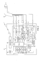
Fig. 2 is a circuit schematic of an exemplary power tool battery pack. -
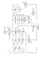
Fig. 3 is a flowchart of different exemplary processes that can be performed by the system ofFig. 1 . -
FIG. 1 illustrates anexemplary system 1000 for enhancing power tools according to the invention. In particular,power tools 200 may be drill, circular saws, reciprocating saws, jigsaws, miter saws, table saws, etc. Some of thepower tools 200 may be cordless and thus be connectable to powertool battery packs 100. Persons skilled in the art shall understand that "battery pack" and "power tool battery pack" as used herein shall mean a set ofrechargeable battery cells 105 disposed in ahousing 101 that for use with a power tool that is powered by an electrical motor, such as adrill 200, circular saw, reciprocating saw, jigsaw, etc. Persons skilled in the art shall recognize that powertool battery pack 100 may be the power tool battery packs disclosed inUS Patent Nos. 7,405,536 ,7,618,741 ,7,602,146 and/or8,044,640 , which are hereby incorporated in full by reference, modified so as to include a communication circuit, and preferably awireless communication circuit 126, as further explained below. -
System 1000 may also includechargers 210 forbattery packs 100, including radio chargers such as the radio charger disclosed inUS Patent No. 6,308,059 , which is hereby incorporated in full by reference. -
System 1000 may also include anon-motorized sensing tool 220, as described inUS Patent No. 8,251,157 , which is hereby incorporated in full by reference. Persons skilled in the art shall recognize thatsensing tool 220 may be an inspection device, a clamp meter, an IR thermometer, an IR camera, an inspection camera, a wall scanner, etc. -
System 1000 may also include aportable power supply 215, such as that described inUS Publication No. 2011/0090726, filed on November 1, 2010 , which is hereby incorporated in full by reference. -
System 1000 may also include acomputing device 250, such as a personal computer, tablet, mobile telephone, smartphone, etc.Computing device 250 is preferably connectable to aserver 270 via the internet. Persons skilled in the art will recognize thatcomputing device 250 preferably connects to the internet via a wireless communication circuit/protocol, such as Wi-Fi, Bluetooth, Zigbee, 3G/4G data systems, etc. - It is desirable that
power tools 200,battery packs 100,non-motorized sensing tools 220,portable power supply 215 and/orchargers 210 be in communication withcomputing device 250. Preferably such communication will occur via awireless communication system 126, such as Wi-Fi, Bluetooth, Zigbee, infrared light, RF, etc. Persons skilled in the art will recognize that other communication schemes may be used that do not require a direct wired connection betweencomputing device 250 and thepower tools 200,battery packs 100, non-motorizedsensing tools 220,portable power supply 215 and/orchargers 210. Such communication schemes may involved transmitting audio signals, using capacitive codes and/or visual codes. -
Computing device 250 may have a program or app that implements the steps shown in the flowchart ofFIG. 3 . A user may begin the program atstep 300 by, for example, selecting the appropriate app/program on hercomputing device 250. Alternatively, the program or app can begin automatically upon connection with or request from thepower tools 200,battery packs 100, non-motorizedsensing tools 220,portable power supply 215 and/orchargers 210. - In response to such selection,
computing device 250 may show several process choices for the user to select (step 305). These process choices may include shopping for tools or related products (step 310), obtaining service information (step 320), refer to construction reference materials (step 330), connect to nearby power tools or products (step 340), or go back to a home menu to end the app (step 350). - For example, if the user selects the shopping process (step 310),
computing device 250 may communicate with aserver 270 via the internet (step 315) that would provide the user information on the different available products, as well as allow the user to shop online for such products. Persons skilled in the art may recognize that thecomputing device 250 may use GPS or cell-location data to identify the closest stores carrying the desired products. - If the user selects the service process (step 320),
computing device 250 may communicate with aserver 270 via the internet (step 324) that provides the user information on the different available services, including the closest repair/service center, contact information, etc. Persons skilled in the art may recognize that thecomputing device 250 may use GPS or cell-location data to identify the closest repair/service center. The user can then call or email the repair/service center (step 328) to schedule an appointment. Persons skilled in the art are further referred toUS Application No. 61/570,484, filed on December 14, 2011 - Persons skilled in the art will recognize that
computing device 250 may transmit data to the repair/service center aboutbattery pack 100,power tool 200,charger 210,portable power supply 215 and/or non-motorizedsensing tool 220, such as cycle numbers, clutch activation count, current draw profiles, and other usage data. Similarly,computing device 250 can transmit such data to other destinations, such as a supervisor's computing device, to alert the supervisor of a user's use or abuse of abattery pack 100,power tool 200,charger 210,portable power supply 215 and/or non-motorizedsensing tool 220. Such data can be used to monitor the user's productivity. - Persons skilled in the art will recognize that the
computing device 250 could be used to record noises originating frompower tool 200 and send those noises to the repair/service center for diagnosis of thepower tool 200. The app could also analyze the noises and provide some troubleshooting advice forpower tool 200. - If the user selects the reference process (step 330), the app would access data stored in memory (step 334). Persons skilled in the art will recognize that the memory could be within or without
computing device 250. Such data could include reference materials, such as handbooks on different construction techniques, the different construction codes, such as the International Building Code, the International Residential Code, the International Plumbing Code, etc. The data could also include other executable routines, like calculator code for converting measurements between different units (e.g., converting feet to meters), calculating stair rise run, baluster spacing, roof pitches, HVAC calculations, etc., as well as different cost estimation tools, landscaping tools, etc. - The user can also choose to connect to nearby power tools, battery packs or other products (step 340). If such process is selected,
computing device 250 would proceed to wirelessly contact all nearby power tools, battery packs and other products (step 342). Once contact has been made,computing device 250 would display a list of nearby power tools, battery pack and other products (step 344). - It may be preferable to color-code the different listed power tools, battery pack and other products. For example, tools that are owned (or paired) with the user can be shown in green. Tools that can't be contacted or accessed by the user can be shown in red. Tools that are owned by colleagues or a group are shown in yellow. Tools that have not been associated with a particular user can be shown in white.
- Similarly, persons skilled in the art will recognize that
computing device 250 may show a list of previously-paired power tools, battery packs and other products, and show the ones that are nearby in one color, while showing the others in another color. In this manner, the user will know which power tools, battery packs and other products are within a certain radius, thus conducting a quick inventory check. - The user can then select a particular power tool, battery pack or other product (step 346). Once a particular power tool, battery pack or other product is selected,
computing device 250 can display different attributes for such product for review. For example, in the case ofbattery pack 100, some of the attributes can include an identifying name (e.g., "Danny's Pack 1"), a picture icon, device model, the charge status, password (for accessing the tool information through another user's phone), temperature, number of charge cycles, etc. Persons skilled in the art will recognize that this information is kept inmemory 128 of thebattery pack 100, which is then transmitted via thewireless communication circuit 126 to computingdevice 250, possibly upon a direct request fromcomputing device 250. - Persons skilled in the art will recognize that some of the attributes can be modified. For example, the identifying name and the picture icon can be modified by the user by selecting a modification process (
steps 347, 348) and inputting the new information. This data can then be wirelessly transmitted to thebattery pack 100 for storage within amemory 128. Persons skilled in the art will recognize that the user can input the new information (as well as other commands, etc.) via a keyboard or touchscreen incomputing device 250 and/or by giving verbal commands which are recognized by thecomputing device 250. - In addition to modifying data related to the battery pack identity, a user can modify data related to the performance of
battery pack 100 viacomputing device 250. For example, a user can program thebattery pack 100 to announce when it is at full charge. This announcement can be communicated via the display ofcomputing device 250, haptic feedback ofcomputing device 250 and/orbattery pack 100, and/or sound emitted by thecomputing device 250 and/or transmitted via a speaker orpiezo 127 ofbattery pack 100. - Similarly, the user can program battery pack 100 (or portable power supply 215) to announce when it is near discharge, when it is hot, when it is outside of communication range with
computing device 250, etc. Persons skilled in the art will recognize that this can be accomplished by monitoring the outputs of voltage monitor 115,current sensor 145,temperature 120, etc. inbattery pack 100. - The user can also disable (and enable) the
battery pack 100 viacomputing device 250. Persons skilled in the art will recognize that "enable" and "disable" refer to the ability ofbattery pack 100 to provide power to apower tool 200 and/or the ability ofbattery pack 100 to receive power from a charger to chargebattery cells 105. The ability (or inability) to provide power to apower tool 200 can be enabled or disabled by controllingdriver circuit 140 to maintainsemiconductor device 130a in an on- or off-state, respectively. Similarly, the ability (or inability) to receive charging power to chargebattery cells 105 can be enabled or disabled by controllingdriver circuit 140 to maintainsemiconductor device 130b in an on- or off-state, respectively. - The user can also program
battery pack 100 so that it is only enabled (and thus providing power and/or accepting charging power) when it is within vicinity ofcomputing device 250. This can be accomplished by computingdevice 250 sending a ping signal tobattery pack 100. Ifbattery pack 100 receives the ping signal, thenbattery pack 100 continues to provide power and/or accept charging power. However, ifbattery pack 100 does not receive a ping signal for a predetermined period of time,battery pack 100 can assume that it is outside of communication range withcomputing device 250 and disable itself (thus not providing power or accepting charging power). - The user can also program
battery pack 100 so that it is only enabled (and thus providing power and/or accepting charging power) when certain conditions are met. For example,battery pack 100 would be enabled for up to a predetermined number of charge cycles, a predetermined time period or number of uses, and then disabled until reset by the user viacomputing device 250. - Persons skilled in the art will recognize that, while the above description is particular to battery packs, the same functionality can be provided for
portable power supply 215, including the ability to enable/disableportable power supply 215, etc. - Similarly, a
power tool 200,non-motorized sensing tool 220 and/orchargers 210 provided with a programmable control and wireless communication circuit may also be contacted viacomputing device 250. For example,power tool 200 can store tool usage patterns, tool conditions, etc., which can be transmitted tocomputing device 250 and to aserver 270 for further analysis, etc. As disclosed above,computing device 250 can display such information. For example,computing device 250 can display the speed (rpm), bevel angles, miter angles, brush wear, the presence or condition of a guard and/or attachment, etc. of thepower tool 200. - Like
battery pack 100,power tool 200 may be programmed to change different attributes or features. For example, a user can set the maximum motor speed or power, or provide a predetermined output (such as half the motor speed or power) when not within the vicinity ofcomputing device 250, etc. Similarly, it may be desirable to control any adjustable feature in a power tool viacomputing device 250. For example, thecomputing device 250 may adjust output pressure in compressors, the amount of grease outputted by a grease gun when the trigger is pulled (persons skilled in the art will recognize thatcomputing device 250 can set a grease gun's pump to run for X pump cycles whenever the trigger is pulled; the higher the number of pump cycles per trigger pull, the larger the amount of grease outputted), the speed of a flywheel-based nailer (such as the one disclosed inUS Patent No. 7,137,541 , which is wholly incorporated herein by reference) in order to adjust for a different nail size or material in which the nail is being driven into, or a desired temperature for a heated jacket (such as the one disclosed inUS Publication No. 2011/0108538 , which is wholly incorporated herein by reference). - The user can also enable and disable different modes of operation, such as allowing/not allowing
power tool 200 to rotate in a reverse direction. As mentioned above, the user can enter such commands via a keyboard or touchscreen oncomputing device 250 and/or by providing verbal commands recognized by computingdevice 250. - Alternatively,
computing device 250 can be used to determine the appropriate attribute or feature to modify. For example,computing device 250 can scan a visual code (such as a bar code or QR code) on an accessory, such as a grinding wheel, via its camera, determine the identity of the accessory and modify the attributes of thepower tool 200 accordingly. In such manner,computing device 250 can determine that, for example, a small grinding wheel has been installed on grinder/power tool 200 and that the maximum speed should be 10000 rpm.Computing device 250 would then program grinder/power tool 200 to not exceed such maximum speed. This would allow a user to use a grinder as a polisher (and vice versa) by selecting the appropriate speed for the desired accessory. -
Computing device 250 could also scan the accessory itself with its camera, such as the shape of a drill bit or router bit, determine the identity and attributes of the accessory based on the resulting image andprogram power tool 200 to match the attributes of the accessory. Alternatively,computing device 250 could scan the workpiece or an identifying code thereon which identifies the type of material constituting the workpiece. Persons skilled in the art will recognize that recognition software can be used to determine the identity of the accessory based on the shape of the accessory.Computing device 250 can then access a database within thecomputing device 250 or in a separate server connectable via a telecommunications network, such as a cellular network, to obtain the information on the different attributes of the accessory. - In addition to information as to the specific accessory, the database may provide the app with information requests. For example, for a particular router bit, the database may instruct the app to ask the user what type of wood is being shaped with the router bit. The app can then customize the power tool settings depending on the type of wood selected by the user, allowing for a more efficient work operation. The app could also indicate whether the router bit is not recommended for that particular type of wood, and/or whether a different router bit is better for shaping that particular type of wood.
- Persons skilled in the art will recognize that, if computing
device 250 has an RFID system,computing device 250 could read an RFID tag disposed on the accessory, then access the database to obtain the attributes of the accessory, and then modify/program power tool 200 accordingly. -
Computing device 250 may also be used to modify the different trigger profiles ofpower tool 200 as described inUS Publication No. 2011/02544272, filed on April 7, 2011 computing device 250 to select between the different trigger profiles applicable topower tool 200. Alternatively, the user can usecomputing device 250 to program a customized trigger profile. - Other customizable features on power tools and other products may include the blink patterns of LEDs, the time period that an LED remains on after releasing a trigger switch, audio beeping patterns for particular conditions in products with speakers or piezos, the selected radio station and/or volume on a
radio charger 210, etc. The app can also turn on and off thepower tool 200 or accessories thereof like a dust collector, open/close gates therein, etc. - If the
power tool 200 has servos that can be used to adjust different features of power tool 200 (such as the miter saw disclosed inUS Patent Publication No. 2001/0000856, filed on January 5, 2001 , and wholly incorporated herein by reference), the app can be used to adjust the different features by controlling the servos. For example, the user can select a bevel angle on thecomputing device 250 and the app will control the bevel angle servo to the desired location. In this manner, the user can program a list of desired workpieces, i.e., a cut list, and the app can control the miter saw/power tool 200 to obtain those cuts. Similarly, the servos can be used to adjust the stroke length in a saw that allows for such adjustment, such as in reciprocating saws or jigsaws. - It may be beneficial to provide servos to perform functions that are difficult to do, like opening a blade clamp on a grinder or a recip saw. Rather than requiring the user to torque open a blade clamp, the user would select such operation in the app.
-
Computing device 250 can also be programmed to control an apparatus, such as the router disclosed inUS Patent Publication No. 2006/0206233, filed on March 9, 2005 , which is wholly incorporated herein by reference. The app can control such apparatus to obtain the cuts selected by the user. - Persons skilled in the art will recognize that these features may be programmed individually, e.g., changing the maximum motor speed, and/or in bulk by selecting a particular setting. In other words, the user can select a LAG bolt setting where the maximum motor speed is adjusted, a particular trigger profile is selected, and a particular alert is chosen, all by selecting one setting on
computing device 250. - Similarly, an owner of
power tool 200 can select settings for different users according to their level of skill. For example, the owner may have a standard setting for experienced users and a lowered power setting for less skilled users. In this manner, the owner can change the torque output or the start-up speed curve (and other attributes) of a rotary hammer/power tool 200 to a setting that is manageable by an inexperienced user, such as a soft-start setting. - Persons skilled in the art will recognize that, if each individual carries an ID or RFID tag that can be scanned or recognized by the
computing device 250 orpower tool 200, the computing device 250 (and/or power tool 200) can detect whenpower tool 200 is used by a new user (due to the presence of the new ID/RFID tag). Computing device 250 (and/or power tool 200) can then change the settings ofpower tool 200 to accommodate the new user. Furthermore,computing device 250 could show a how-to-use video or provide other information to the new user, especially if the new user is noted to be an inexperienced user. - A user can even select specific alerts for the
power tool 200, as she did forbattery pack 100. For example, the user can programcomputing device 250 to display a warning when a specific condition occurs. These conditions may include brush wear beyond a selected threshold, high current draw (possibly representing an overload condition), etc. - Persons skilled in the art will recognize that these alerts can have a visual component, such as an alert window displayed on the screen of
computing device 250, and/or an audio component, such as a sound or song (possibly selected by the user) played through the speaker(s) ofcomputing device 250 or aradio charger 210, or through an earphone connected tocomputing device 250. Persons skilled in the art will recognize that such earphone could be wireless connected tocomputing device 250 via BlueTooth, or could be connected via a wire to thecomputing device 250. - Furthermore, a user can also use
computing device 250 to locate the selected power tool, battery pack or other product (step 349). Due to the wireless communication betweencomputing device 250 andbattery pack 100, it is possible to send a command fromcomputing device 250 tobattery pack 100 to start emitting a sound via speaker/piezo 127, so as to assist in locatingsuch battery pack 100. It is also possible to have thecomputing device 250 poll all nearby battery packs 100 for a particular state. Thus computingdevice 250 can determine the battery pack with the highest/lowest charge, highest/lowest temperature, most charge cycles, etc., then send a command to theparticular battery pack 100 to start emitting a sound. - The user can also select going back to a home menu to end the app (step 350). This would end the app (step 355) and go to a home menu of the
computing device 250. - The app can also monitor the
battery pack 100,charger 210 and/or power tool 200 (step 360). The app can enter a monitoring state automatically and/or when selected by the user. During this monitoring process, the app can keep track of power tool usage, present current draw, etc. and store and/or use that information for analysis by a service department. In this manner, the service department can determine whether apower tool 200 has been abused. - The app can also use that information to better utilize the
power tool 200. For example, the app can receive PWM, voltage and/or current draw information frombattery pack 100 and/orpower tool 200 and establish a macro that would allow the user to repeat the current draw. Persons skilled in the art will recognize that such current draw profile can represent a torque curve for driving a fastener into a surface. Having a repeatable draw profile will allow the user to easily set a custom torque setting. - Persons skilled in the art will recognize that an app can be looking for similar patterns and adjust
battery pack 100 and/orpower tool 200 accordingly for better efficiency, effectively learning the user's use patterns. The app can do such analysis on data patterns, or even in real time. For example, the app can receive current information, trigger position and/or speed information, and runpower tool 200 using that information to maximize run-time. Other information that the app can monitor includes bias force/bias load, gear settings, battery voltage, the presence of on-tool guard or side handles, etc. - Persons skilled in the art will recognize that, if the app monitors the presence of on-tool guards or side handles, the app can prevent use of the
power tool 200 if the guards or side handles are not detected, and/or limit the power output for better control. Persons skilled in the art will also recognize that the presence of these guards and side handles can be detected by providing, for example, switches onpower tool 200 that get activated once the guards or side handles are installed. - Similarly, if the app monitors motor current draw and gear setting, the app can select and/or indicate the best gear ratio (or speed setting) to run at optimum efficiency. If the motor is drawing a lot of current and the transmission is set at a high speed, the app may alert the user to switch to a lower speed or may switch the gear setting automatically.
- Persons skilled in the art will understand that the app can limit the power tool's output speed and torque by monitoring bias force/bias load if the app determines that the bias load is not adequate to keep a screwdriver bit engaged to a screw. The app could also turn off or delay the impacts provided by the transmission of
power tool 200. - The app can also use the sensors in the
computing device 250 to determine working conditions and adjust the usage ofbattery pack 100 and/orpower tool 200. For example, if the user wears thecomputing device 250 on his wrist and the app notices a sudden movement (by monitoring the accelerometers in the computing device 250), the app can shut down thepower tool 200 by turning offbattery pack 100 orpower tool 200, or limit the amount of power provided bybattery pack 100 or topower tool 200. The accelerometers in thecomputing device 250 can also be used to monitor vibration. When a certain threshold of vibration is reached, the user can be alerted to take a rest break. - Similarly, the app can adjust the brightness of the LEDs in
power tool 200 according to the output from the ambient light sensors ofcomputing device 250. For example, if the ambient light sensors ofcomputing device 250 detect a dark environment, the app can increase or decrease the brightness of the LEDs. - Additionally, the app can use the on-board microphone of
computing device 250 to listen to the ambient noise. The app can then create an opposite soundwave and play it through an on-board speaker and/or transmit it to theradio charger 210. Persons skilled in the art will recognize that playing an opposite soundwave will cancel or lower the ambient noise. - The
computing device 250 can also controlpower tool 200 and/orcharger 210 according to the use of thecomputing device 250. For example, if computingdevice 250 receives a phone call, the app can turn offpower tool 200 and/or lower the volume onradio charger 210. - Persons skilled in the art will understand that
computing device 250 can also be used for controlling multiple items at the same time. For example, when the app detects apower tool 200 being turned on, such as when the user pulls on a trigger, the app can increase the volume onradio charger 210. - The app can also transmit data (step 370) about
battery pack 100,power tool 200,charger 210,portable power supply 215 and/ornon-motorized sensing tool 220 to specific destinations. For example, awall scanner 220 may transmit data about a scanned wall viacomputing device 250 to an archive or to a store website. Similarly, the image data received from an IR camera can be sent to thecomputing device 250 and made part of a document drafted incomputing device 250, which in turn can be emailed or transmitted to a client. - The description of the invention is merely exemplary in nature and, thus, variations that do not depart from the gist of the invention are intended to be within the scope of the invention. Such variations are not to be regarded as a departure from the scope of the invention.
Claims (9)
- A system comprising:at least one of a power tool battery pack, a power tool, a portable power supply, a non-motorized sensing tool, and a power tool battery pack charger;a separate computing device for communicating wirelessly with the at least one of the power tool battery pack, the power tool, the portable power supply, the non-motorized sensing tool, and the power tool battery pack charger;wherein the computing device monitors a data value representative of a condition of the at least one of the power tool battery pack, the power tool, the portable power supply, the non-motorized sensing tool, and the power tool battery pack charger, and the computing device performs an action responsive to the monitored data value.
- The system of Claim 1, wherein the computing device and at least one of the power tool battery pack, the power tool, the portable power supply, the non-motorized sensing tool, and the power tool battery pack charger communicate via a wireless communication system consisting of at least one of Wi-Fi, BlueTooth, Zigbee, infrared light and radio frequency signals.
- The system of Claim 1, wherein the computing device monitors at least one of the group consisting of voltage, current, temperature, speed, bevel angle, miter angle, brush wear, presence or condition of a guard, presence or condition of an attachment, bias force, gear setting, voltage, current draw, and accelerometer output of the computing device.
- The system of Claim 1, wherein the action performed by the computing device is displaying the monitored data value.
- The system of Claim 4, wherein the monitored data value is at least one of the speed, bevel angle, miter angle, brush wear, presence or condition of a guard, presence or condition of an attachment.
- A system comprising:at least one of a power tool battery pack, a power tool, a portable power supply, a non-motorized sensing tool, and a power tool battery pack charger, the at least one of the power tool battery pack, the power tool, the portable power supply, the non-motorized sensing tool, and the power tool battery pack charger having a memory;a separate computing device for communicating wirelessly with the at least one of the power tool battery pack, the power tool, the portable power supply, the non-motorized sensing tool, and the power tool battery pack charger;wherein the computing device transmits a data value to the at least one of the power tool battery pack, the power tool, the portable power supply, the non-motorized sensing tool, and the power tool battery pack charger, and the at least one of the power tool battery pack, the power tool, the portable power supply, the non-motorized sensing tool, and the power tool battery pack charger performs an action responsive to the transmitted data value.
- The system of Claim 6 wherein the action is at least one of a group consisting of announcing when the power tool battery pack is at full charge, announcing when the power tool battery pack has exceeded a temperature threshold, disabling the at least one of the power tool battery pack, the power tool, the portable power supply, the non-motorized sensing tool, and the power tool battery pack charger, adjusting a working parameter of the at least one of the power tool battery pack, the power tool, the portable power supply, the non-motorized sensing tool, and the power tool battery pack charger, adjusting a mechanism of the at least one of the power tool battery pack, the power tool, the portable power supply, the non-motorized sensing tool, and the power tool battery pack charger, and emitting a sound.
- The system of Claim 7, wherein the working parameter is at least one of the group consisting of an amount of delivered grease, a speed, a temperature, a rotational direction, a lighting pattern, a desired radio station, a miter angle, a bevel angle, a maximum torque output, a maximum current draw, an audio volume, and a gear setting.
- The system of Claim 6, wherein the computing device and at least one of the power tool battery pack, the power tool, the portable power supply, the non-motorized sensing tool, and the power tool battery pack charger communicate via a wireless communication system consisting of at least one of Wi-Fi, BlueTooth, Zigbee, infrared light and radio frequency signals.
Applications Claiming Priority (2)
| Application Number | Priority Date | Filing Date | Title |
|---|---|---|---|
| US201261664428P | 2012-06-26 | 2012-06-26 | |
| US13/835,060 US20140107853A1 (en) | 2012-06-26 | 2013-03-15 | System for enhancing power tools |
Publications (2)
| Publication Number | Publication Date |
|---|---|
| EP2680093A2 true EP2680093A2 (en) | 2014-01-01 |
| EP2680093A3 EP2680093A3 (en) | 2017-05-03 |
Family
ID=48746293
Family Applications (1)
| Application Number | Title | Priority Date | Filing Date |
|---|---|---|---|
| EP13173747.0A Withdrawn EP2680093A3 (en) | 2012-06-26 | 2013-06-26 | System for enhancing power tools |
Country Status (2)
| Country | Link |
|---|---|
| US (6) | US20140107853A1 (en) |
| EP (1) | EP2680093A3 (en) |
Cited By (26)
| Publication number | Priority date | Publication date | Assignee | Title |
|---|---|---|---|---|
| WO2015153398A1 (en) | 2014-04-02 | 2015-10-08 | Ridge Tool Company | Electronic tool lock |
| CN105882444A (en) * | 2016-04-15 | 2016-08-24 | 张晓晓 | IOT (Internet of Things) technology based automobile charging pile device with mobile payment |
| EP3064323A1 (en) * | 2015-02-02 | 2016-09-07 | Black & Decker Inc. | Power tool system |
| CN106457549A (en) * | 2014-05-26 | 2017-02-22 | 株式会社牧田 | Device for power tool |
| DE102016209253A1 (en) | 2015-11-24 | 2017-05-24 | Robert Bosch Gmbh | System of at least one hand tool, at least a first interface and at least one electrical product |
| WO2017151045A1 (en) * | 2016-03-01 | 2017-09-08 | Husqvarna Ab | Wearable apparatus and system for use with outdoor power equipment |
| US9983312B2 (en) | 2013-06-21 | 2018-05-29 | Duracell U.S. Operations, Inc. | Systems and methods for remotely determining a battery characteristic |
| WO2018166766A1 (en) * | 2017-03-14 | 2018-09-20 | Robert Bosch Gmbh | Tool system and method |
| EP3382655A1 (en) * | 2017-03-29 | 2018-10-03 | Robert Bosch GmbH | Method for generating at least one identifier of at least one object |
| US10151802B2 (en) | 2016-11-01 | 2018-12-11 | Duracell U.S. Operations, Inc. | Reusable battery indicator with electrical lock and key |
| EP3332295A4 (en) * | 2015-08-05 | 2019-01-02 | Tetrascience, Inc. | Methods, systems, and devices for monitoring and controlling tools |
| US10184988B2 (en) | 2012-12-27 | 2019-01-22 | Duracell U.S. Operations, Inc. | Remote sensing of remaining battery capacity using on-battery circuitry |
| US10297875B2 (en) | 2015-09-01 | 2019-05-21 | Duracell U.S. Operations, Inc. | Battery including an on-cell indicator |
| US10483634B2 (en) | 2016-11-01 | 2019-11-19 | Duracell U.S. Operations, Inc. | Positive battery terminal antenna ground plane |
| CN110658757A (en) * | 2019-09-20 | 2020-01-07 | 烟台英博新材料科技有限公司 | a wireless feedback device |
| US10540728B2 (en) | 2016-03-09 | 2020-01-21 | Husqvarna Ab | Locating substitute construction tools within a construction worksite |
| US10608293B2 (en) | 2016-11-01 | 2020-03-31 | Duracell U.S. Operations, Inc. | Dual sided reusable battery indicator |
| US10818197B2 (en) | 2016-03-10 | 2020-10-27 | Husqvarna Ab | Teaching mode for construction devices |
| US10818979B2 (en) | 2016-11-01 | 2020-10-27 | Duracell U.S. Operations, Inc. | Single sided reusable battery indicator |
| US10916850B2 (en) | 2013-05-23 | 2021-02-09 | Duracell U.S. Operations, Inc. | Omni-directional antenna for a cylindrical body |
| US10964980B2 (en) | 2014-05-30 | 2021-03-30 | Duracell U.S. Operations, Inc. | Indicator circuit decoupled from a ground plane |
| US11022955B2 (en) | 2014-04-02 | 2021-06-01 | Ridge Tool Company | Smart tool systems |
| US11024891B2 (en) | 2016-11-01 | 2021-06-01 | Duracell U.S. Operations, Inc. | Reusable battery indicator with lock and key mechanism |
| WO2021121809A1 (en) * | 2019-12-18 | 2021-06-24 | Robert Bosch Gmbh | Method for a user interaction with an electric device and/or an electric device accessory and system for performing the method |
| US11837754B2 (en) | 2020-12-30 | 2023-12-05 | Duracell U.S. Operations, Inc. | Magnetic battery cell connection mechanism |
| US20250196240A1 (en) * | 2022-03-31 | 2025-06-19 | Robert Bosch Gmbh | Method for Operating a Machine Tool with a Gentle Start-Up |
Families Citing this family (85)
| Publication number | Priority date | Publication date | Assignee | Title |
|---|---|---|---|---|
| US8269612B2 (en) | 2008-07-10 | 2012-09-18 | Black & Decker Inc. | Communication protocol for remotely controlled laser devices |
| US9467862B2 (en) | 2011-10-26 | 2016-10-11 | Milwaukee Electric Tool Corporation | Wireless tracking of power tools and related devices |
| US9525293B2 (en) | 2011-12-30 | 2016-12-20 | Makita Corporation | Battery charger having angled wall in battery receiving opening, and battery pack charging system and cordless power tool system including same |
| US9908182B2 (en) | 2012-01-30 | 2018-03-06 | Black & Decker Inc. | Remote programming of a power tool |
| US20130327552A1 (en) | 2012-06-08 | 2013-12-12 | Black & Decker Inc. | Power tool having multiple operating modes |
| GB2519027B (en) | 2012-07-17 | 2020-07-08 | Milwaukee Electric Tool Corp | Universal protocol for power tools |
| US9781496B2 (en) * | 2012-10-25 | 2017-10-03 | Milwaukee Electric Tool Corporation | Worksite audio device with wireless interface |
| US9367062B2 (en) * | 2012-12-31 | 2016-06-14 | Robert Bosch Gmbh | System and method for operational data retrieval from a power tool |
| WO2015061370A1 (en) | 2013-10-21 | 2015-04-30 | Milwaukee Electric Tool Corporation | Adapter for power tool devices |
| WO2015094052A1 (en) | 2013-12-19 | 2015-06-25 | Husqvarna Ab | Obstacle detection for a robotic working tool |
| CN112019593A (en) | 2015-01-29 | 2020-12-01 | 苏州宝时得电动工具有限公司 | Data transmission system for power tools |
| US9917457B2 (en) | 2015-02-02 | 2018-03-13 | Black & Decker Inc. | Power tool with USB connection |
| DE102015002455B4 (en) * | 2015-02-25 | 2024-02-08 | Thomas Allmendinger | miter saw |
| US10427227B2 (en) | 2015-03-12 | 2019-10-01 | Robert Bosch Tool Corporation | Drop arm reset method |
| US10189098B2 (en) * | 2015-03-12 | 2019-01-29 | Robert Bosch Tool Corporation | Diagnostic and maintenance operation for a saw |
| US10821529B2 (en) | 2015-03-12 | 2020-11-03 | Robert Bosch Tool Corporation | Power tool with improved belt tensioning |
| US10322522B2 (en) | 2015-03-12 | 2019-06-18 | Robert Bosch Tool Corporation | Electrical configuration for object detection system in a saw |
| US10799964B2 (en) | 2015-03-12 | 2020-10-13 | Robert Bosch Tool Corporation | Table saw with pulley alignment mechanism |
| US10758989B2 (en) | 2015-03-12 | 2020-09-01 | Robert Bosch Tool Corporation | System and method for sensing cable fault detection in a saw |
| US10369642B2 (en) | 2015-03-12 | 2019-08-06 | Robert Bosch Tool Corporation | Power tool with protected circuit board orientation |
| US10493543B2 (en) | 2015-03-12 | 2019-12-03 | Robert Bosch Tool Corporation | Power tool motor with reduced electrical noise |
| US10603770B2 (en) | 2015-05-04 | 2020-03-31 | Milwaukee Electric Tool Corporation | Adaptive impact blow detection |
| AU2016257438B2 (en) | 2015-05-04 | 2019-03-07 | Milwaukee Electric Tool Corporation | Power tool and method for wireless communication |
| US10295990B2 (en) | 2015-05-18 | 2019-05-21 | Milwaukee Electric Tool Corporation | User interface for tool configuration and data capture |
| US10850380B2 (en) | 2015-06-02 | 2020-12-01 | Milwaukee Electric Tool Corporation | Multi-speed power tool with electronic clutch |
| US10339496B2 (en) | 2015-06-15 | 2019-07-02 | Milwaukee Electric Tool Corporation | Power tool communication system |
| US10618151B2 (en) | 2015-06-15 | 2020-04-14 | Milwaukee Electric Tool Corporation | Hydraulic crimper tool |
| US10380883B2 (en) | 2015-06-16 | 2019-08-13 | Milwaukee Electric Tool Corporation | Power tool profile sharing and permissions |
| US10345797B2 (en) | 2015-09-18 | 2019-07-09 | Milwaukee Electric Tool Corporation | Power tool operation recording and playback |
| SE1551240A1 (en) * | 2015-09-29 | 2017-03-30 | Husqvarna Ab | Apparatus and system for providing a connected battery |
| ES2844628T3 (en) | 2015-10-30 | 2021-07-22 | Milwaukee Electric Tool Corp | Remote control, configuration and monitoring of lights |
| US11424601B2 (en) | 2015-11-02 | 2022-08-23 | Milwaukee Electric Tool Corporation | Externally configurable worksite power distribution box |
| DE102015226084A1 (en) | 2015-12-18 | 2017-06-22 | Robert Bosch Gmbh | Hand tool machine with a communication interface |
| DE102015226088A1 (en) * | 2015-12-18 | 2017-06-22 | Robert Bosch Gmbh | Hand tool machine with a gear shift unit |
| DE102015226194A1 (en) * | 2015-12-21 | 2017-06-22 | Robert Bosch Gmbh | Mobile functional device |
| WO2017120165A1 (en) | 2016-01-05 | 2017-07-13 | Milwaukee Electric Tool Corporation | Vibration reduction system and method for power tools |
| EP3200313A1 (en) * | 2016-01-28 | 2017-08-02 | Black & Decker Inc. | System for enhancing power tools |
| US10562116B2 (en) | 2016-02-03 | 2020-02-18 | Milwaukee Electric Tool Corporation | System and methods for configuring a reciprocating saw |
| EP4056321A1 (en) | 2016-02-25 | 2022-09-14 | Milwaukee Electric Tool Corporation | Power tool including an output position sensor |
| US10628898B2 (en) | 2016-03-07 | 2020-04-21 | Husqvarna Ab | Identifying and locating a substitute battery for a construction job site power tool |
| AU2017201788B2 (en) | 2016-03-16 | 2019-02-07 | Tti (Macao Commercial Offshore) Limited | Power tool battery pack with wireless communication |
| AU201615156S (en) | 2016-03-17 | 2016-12-09 | Tti Macao Commercial Offshore Ltd | Battery pack |
| AU201615153S (en) | 2016-03-17 | 2016-12-09 | Tti Macao Commercial Offshore Ltd | Battery pack |
| AU201615158S (en) | 2016-03-17 | 2016-12-09 | Tti Macao Commercial Offshore Ltd | Battery pack |
| DE112017001713T5 (en) * | 2016-03-30 | 2018-12-20 | Husqvarna Ab | DEVICE FOR SETTING A CONSTRUCTION DEVICE SCHEDULE |
| EP3307489B1 (en) * | 2016-05-06 | 2019-07-03 | Lukas Hydraulik GmbH | Method for operating an implement or rescue equipment and implement or rescue equipment |
| TWM555274U (en) | 2016-06-06 | 2018-02-11 | 米沃奇電子工具公司 | Mobile device for connection to a power tool device |
| US11622392B2 (en) | 2016-06-06 | 2023-04-04 | Milwaukee Electric Tool Corporation | System and method for establishing a wireless connection between power tool and mobile device |
| US10376766B2 (en) | 2016-07-29 | 2019-08-13 | Black & Decker Inc. | Scoreboard and system |
| SE540232C2 (en) * | 2016-09-14 | 2018-05-08 | Husqvarna Ab | Improved less of controlling battery operated power tool |
| DE102016217833A1 (en) * | 2016-09-19 | 2018-03-22 | Robert Bosch Gmbh | Method for releasing an active operating state of a hand tool according to whether a protective equipment is carried or carried by an operator of the power tool |
| USD853216S1 (en) | 2017-01-17 | 2019-07-09 | Tti (Macao Commercial Offshore) Limited | Power tool |
| TWD200631S (en) | 2017-01-17 | 2019-11-01 | Tti Macao Commercial Offshore Ltd | Battery pack |
| USD926674S1 (en) | 2017-01-17 | 2021-08-03 | Tti (Macao Commercial Offshore) Limited | Battery pack with communication terminal |
| USD853813S1 (en) | 2017-01-17 | 2019-07-16 | Tti (Macao Commercial Offshore) Limited | Power tool |
| CN111093452A (en) | 2017-07-05 | 2020-05-01 | 米沃奇电动工具公司 | Adapter for communication between power tools |
| US20190097668A1 (en) | 2017-09-25 | 2019-03-28 | Black & Decker Inc. | Construction jobsite computer data network and location services |
| CN112055636B (en) * | 2018-01-24 | 2024-07-05 | 米沃奇电动工具公司 | Power tools including machine learning blocks |
| WO2019190996A1 (en) | 2018-03-26 | 2019-10-03 | Milwaukee Electric Tool Corporation | High-power battery-powered portable power source |
| DE102018111652A1 (en) * | 2018-05-15 | 2019-11-21 | STAHLWILLE Eduard Wille GmbH & Co. KG | Tool and method for operating a tool |
| US11271415B2 (en) | 2018-05-18 | 2022-03-08 | Milwaukee Electric Tool Corporation | Portable power source |
| US11861446B2 (en) | 2018-07-24 | 2024-01-02 | Illinois Tool Works Inc. | Method and apparatus for using encoded information for material preparation and analysis equipment |
| US11011053B2 (en) | 2018-07-31 | 2021-05-18 | Tti (Macao Commercial Offshore) Limited | Systems and methods for remote power tool device control |
| US11557187B2 (en) | 2018-08-14 | 2023-01-17 | Black & Decker Inc. | System and method for deterring theft |
| US11763610B2 (en) | 2018-09-13 | 2023-09-19 | Milwaukee Electric Tool Corporation | Anti-theft systems and devices for battery-powered power tools |
| US11621531B2 (en) | 2018-09-28 | 2023-04-04 | Hubbell Incorporated | Power tool with crimp localization |
| CN216229210U (en) | 2019-01-11 | 2022-04-08 | 米沃奇电动工具公司 | Battery pack for powering power tools |
| US10987794B2 (en) * | 2019-01-23 | 2021-04-27 | Gustav Klauke Gmbh | Accumulator-operated hand-held working apparatus as well as method for operating such an apparatus |
| EP3972783A4 (en) * | 2019-05-20 | 2023-06-14 | Black & Decker, Inc. | VOICE REACTIVE BUILDING TOOL |
| USD933010S1 (en) | 2019-05-29 | 2021-10-12 | Milwaukee Electric Tool Corporation | Portable power source |
| US11571803B2 (en) | 2019-05-30 | 2023-02-07 | Milwaukee Electric Tool Corporation | Power tool with combined chip for wireless communications and power tool control |
| AU2020316444B2 (en) | 2019-07-23 | 2026-02-12 | Milwaukee Electric Tool Corporation | Power tool including a machine learning block for controlling a seating of a fastener |
| US11446747B2 (en) * | 2019-10-29 | 2022-09-20 | Hilti Aktiengesellschaft | Systems and methods for calculating usage of power tools with a sensor tag |
| JP7523913B2 (en) | 2020-01-15 | 2024-07-29 | 株式会社マキタ | Electrical implements and site electrical systems |
| ES2844589B2 (en) * | 2020-01-22 | 2024-07-16 | Martinez Y Gascon S A | System for monitoring the use of hand tools, hand tool and procedure for monitoring the use of hand tools |
| AT523566A1 (en) * | 2020-03-10 | 2021-09-15 | Weber Hyraulik Gmbh | Method for operating a rescue system with a mobile rescue device |
| AT523567B1 (en) | 2020-03-10 | 2023-07-15 | Weber Hydraulik Gmbh | Mobile rescue device, as well as computer-implemented procedure for anti-theft protection of the mobile rescue device |
| US11404886B2 (en) | 2020-04-17 | 2022-08-02 | Snap-On Incorporated | Communicating battery charger |
| EP4168866A4 (en) | 2020-06-21 | 2024-07-17 | Hubbell Incorporated | POWER TOOL WITH CRIMP IMAGE |
| CN115070701B (en) * | 2021-03-11 | 2025-06-10 | 里奇工具公司 | Variable force compaction tool system |
| US11270086B1 (en) | 2021-04-06 | 2022-03-08 | Chevron U.S.A. Inc. | System and method for tracking objects |
| DE202021105910U1 (en) * | 2021-10-28 | 2023-02-01 | Einhell Germany Ag | Project support through voice output of a battery pack |
| DE102022103305A1 (en) * | 2022-02-11 | 2023-08-17 | Einhell Germany Ag | Project support when using an electrical device with a battery pack |
| JP2023180161A (en) * | 2022-06-08 | 2023-12-20 | パナソニックホールディングス株式会社 | Power tools, power tool systems, control methods and programs |
| EP4534955B1 (en) | 2023-08-07 | 2026-04-29 | Stanley Black & Decker, Inc. | Laser level assembly |
Citations (14)
| Publication number | Priority date | Publication date | Assignee | Title |
|---|---|---|---|---|
| US20010000856A1 (en) | 1998-11-12 | 2001-05-10 | O'banion Michael L. | Miter saw workstation |
| US6308059B1 (en) | 1997-12-12 | 2001-10-23 | Joseph Domes | Ruggedized tradesworkers radio |
| US20060206233A1 (en) | 2005-03-09 | 2006-09-14 | Carpenter David A | Method and apparatus for cutting a workpiece |
| US7137541B2 (en) | 2004-04-02 | 2006-11-21 | Black & Decker Inc. | Fastening tool with mode selector switch |
| EP1780867A2 (en) * | 2005-10-28 | 2007-05-02 | BLACK & DECKER INC. | Battery pack for cordless power tools |
| US7405536B2 (en) | 2003-10-08 | 2008-07-29 | Black & Decker Inc. | Battery pack-detecting charger |
| US7602146B2 (en) | 2003-10-14 | 2009-10-13 | Black & Decker Inc. | Protection methods, protection circuits and protection devices for secondary batteries, a power tool, charger and battery pack adapted to provide protection against fault conditions in the battery pack |
| US7618741B2 (en) | 2005-10-31 | 2009-11-17 | Black & Decker Inc. | Battery pack, charger and terminal block arrangements for cordless power tool system |
| US20110090726A1 (en) | 2007-02-26 | 2011-04-21 | Black & Decker Inc. | Portable alternating current inverter having reduced impedance losses |
| US20110108538A1 (en) | 2009-11-06 | 2011-05-12 | Rick Gray | Electrically heated garment |
| US20110254472A1 (en) | 2010-04-07 | 2011-10-20 | Black And Decker Inc. | Power tool having a non-linear trigger-speed profile |
| US8044640B2 (en) | 2008-10-07 | 2011-10-25 | Black & Decker Inc. | Method for stepping current output by a battery charger |
| WO2012067261A1 (en) * | 2010-11-19 | 2012-05-24 | ソニー株式会社 | Secondary battery cell, battery pack, and power consumption equipment |
| US8251157B2 (en) | 2008-03-07 | 2012-08-28 | Milwaukee Electric Tool Corporation | Battery pack for use with a power tool and a non-motorized sensing tool |
Family Cites Families (144)
| Publication number | Priority date | Publication date | Assignee | Title |
|---|---|---|---|---|
| US4151521A (en) * | 1977-09-15 | 1979-04-24 | Wirth John C | Power tool theft alarm |
| US4514732A (en) * | 1982-08-23 | 1985-04-30 | General Electric Company | Technique for increasing battery life in remote control transmitters |
| US4990896A (en) * | 1989-05-09 | 1991-02-05 | Gray William F | Light responsive device for monitoring on-line indicator lights |
| US6850252B1 (en) * | 1999-10-05 | 2005-02-01 | Steven M. Hoffberg | Intelligent electronic appliance system and method |
| US7613590B2 (en) * | 1992-11-17 | 2009-11-03 | Health Hero Network, Inc. | Modular microprocessor-based power tool system |
| US5459671A (en) * | 1993-02-19 | 1995-10-17 | Advanced Micro Devices, Inc. | Programmable battery controller |
| IL116667A0 (en) * | 1996-01-03 | 1996-05-14 | Omat Ltd | Apparatus and method for cnc machine tooling |
| US6418829B1 (en) * | 1994-05-06 | 2002-07-16 | Thomas Stanley Pilchowski | Power tool safety device |
| US5705929A (en) * | 1995-05-23 | 1998-01-06 | Fibercorp. Inc. | Battery capacity monitoring system |
| US5587931A (en) * | 1995-10-20 | 1996-12-24 | Tri-Way Machine Ltd. | Tool condition monitoring system |
| US5710503A (en) * | 1996-02-01 | 1998-01-20 | Aims Systems, Inc. | On-line battery monitoring system with defective cell detection capability |
| US6239579B1 (en) * | 1996-07-05 | 2001-05-29 | Estco Battery Management Inc. | Device for managing battery packs by selectively monitoring and assessing the operative capacity of the battery modules in the pack |
| DE19716520B4 (en) * | 1997-04-19 | 2007-04-19 | Robert Bosch Gmbh | Formed as a circuit device for detecting operating variables of electric motors and electric motor |
| US6308138B1 (en) * | 1997-07-28 | 2001-10-23 | Tri-Way Machine Ltd. | Diagnostic rule base tool condition monitoring system |
| US6072299A (en) * | 1998-01-26 | 2000-06-06 | Medtronic Physio-Control Manufacturing Corp. | Smart battery with maintenance and testing functions |
| JPH11215725A (en) * | 1998-01-29 | 1999-08-06 | Oki Electric Ind Co Ltd | Charge state determination method, charge state determination device, and charging device |
| US6415094B1 (en) * | 1998-03-16 | 2002-07-02 | Charles H. Wissman | Method and apparatus for extending the recording time of a remotely controllable electronic device using a hand-held autonomous remote control |
| US7640007B2 (en) * | 1999-02-12 | 2009-12-29 | Fisher-Rosemount Systems, Inc. | Wireless handheld communicator in a process control environment |
| US6204637B1 (en) * | 1999-03-16 | 2001-03-20 | International Business Machines Corporation | Method and system for remotely supplying power through an automated power adapter to a data processing system |
| FI111760B (en) * | 1999-04-16 | 2003-09-15 | Metso Automation Oy | Wireless control of a field device in an industrial process |
| US6536536B1 (en) * | 1999-04-29 | 2003-03-25 | Stephen F. Gass | Power tools |
| US6618630B1 (en) * | 1999-07-08 | 2003-09-09 | Fisher-Rosemount Systems, Inc. | User interface that integrates a process control configuration system and a field device management system |
| US7024321B1 (en) * | 2000-07-20 | 2006-04-04 | Qualcomm, Incorporated | Battery monitoring system with low power and end-of-life messaging and shutdown |
| IT1320621B1 (en) * | 2000-09-05 | 2003-12-10 | Wrap Spa | METHOD, SYSTEM AND APPARATUS FOR DATA TRANSMISSION ON THE ELECTRICITY NETWORK |
| CN1241079C (en) * | 2000-10-26 | 2006-02-08 | 西铁城时计株式会社 | Automatic generation method and device of processing program |
| US6668212B2 (en) * | 2001-06-18 | 2003-12-23 | Ingersoll-Rand Company | Method for improving torque accuracy of a discrete energy tool |
| US20060240806A1 (en) * | 2001-07-18 | 2006-10-26 | Saban Demirbasa | Data security device |
| US7136914B2 (en) * | 2001-08-06 | 2006-11-14 | Ricoh Company, Ltd. | System, computer program product and method for managing and controlling a local network of electronic devices |
| US6571179B2 (en) * | 2001-08-24 | 2003-05-27 | Xerox Corporation | Intelligent power tool |
| EP1308810B1 (en) * | 2001-09-05 | 2005-11-16 | Mikron Comp-Tec AG | A method and an operator support system for assisting an operator in setting machine parameters |
| US6983212B2 (en) * | 2001-11-27 | 2006-01-03 | American Power Conversion Corporation | Battery management system and method |
| WO2003047064A2 (en) * | 2001-11-27 | 2003-06-05 | Xsilogy, Inc. | Remote battery monitoring systems and sensors |
| JP2003256084A (en) * | 2002-03-06 | 2003-09-10 | Fujitsu Ltd | Battery monitoring system |
| US20060076385A1 (en) * | 2002-04-18 | 2006-04-13 | Etter Mark A | Power tool control system |
| EP1367685A1 (en) * | 2002-05-31 | 2003-12-03 | Whirlpool Corporation | Electronic system for power consumption management of appliances |
| US7474228B2 (en) * | 2002-06-19 | 2009-01-06 | Tarma, Llc | Battery monitor |
| US7394394B2 (en) * | 2002-06-19 | 2008-07-01 | Tarma, L.L.C. | Battery monitor with wireless remote communication |
| US7182147B2 (en) * | 2002-06-27 | 2007-02-27 | Snap-On Incorporated | Tool apparatus, system and method of use |
| US7054696B2 (en) * | 2002-07-18 | 2006-05-30 | Black & Decker Inc. | System and method for data retrieval in AC power tools via an AC line cord |
| US7324462B1 (en) * | 2002-07-25 | 2008-01-29 | 3Com Corporation | Methods for discovering devices within a wireless network |
| JP2004094607A (en) * | 2002-08-30 | 2004-03-25 | Matsushita Electric Ind Co Ltd | Portable information device, method and program for optimizing state of charge of battery, battery management server, and method and program for optimizing state of charge of battery-powered electric device |
| US7034659B2 (en) * | 2002-09-23 | 2006-04-25 | Intermec Ip Corp. | Method and system for limiting use of electronic equipment |
| US20080255684A1 (en) * | 2002-11-18 | 2008-10-16 | Universiti Putra Malaysia | Artificial intelligence device and corresponding methods for selecting machinability data |
| EP1447177B1 (en) * | 2003-02-05 | 2011-04-20 | Makita Corporation | Power tool with a torque limiter using only rotational angle detecting means |
| JP4329369B2 (en) * | 2003-03-20 | 2009-09-09 | パナソニック電工株式会社 | Power tool usage support method and apparatus |
| US7388350B1 (en) * | 2003-05-06 | 2008-06-17 | Cypress Semiconductor Corporation | Battery with electronic compartment |
| US8310201B1 (en) * | 2003-05-06 | 2012-11-13 | Cypress Semiconductor Corporation | Battery with electronic compartment |
| US6990431B2 (en) * | 2003-06-23 | 2006-01-24 | Municipal And Industrial Data Labs, Inc. | System and software to monitor cyclic equipment efficiency and related methods |
| US20050242971A1 (en) * | 2003-07-15 | 2005-11-03 | Gregory Dryer | System and method for safe disablement of mobile pieces of equipment (MPEs) |
| US7330129B2 (en) * | 2003-07-16 | 2008-02-12 | Black & Decker Inc. | System and method for data retrieval in AC power tools via an AC line cord |
| US7339347B2 (en) * | 2003-08-11 | 2008-03-04 | Reserve Power Cell, Llc | Apparatus and method for reliably supplying electrical energy to an electrical system |
| US20050267776A1 (en) * | 2003-08-22 | 2005-12-01 | Selby David A | Combo kit and method of providing a combo kit |
| US7184905B2 (en) * | 2003-09-29 | 2007-02-27 | Stefan Donald A | Method and system for monitoring power supplies |
| PL1533767T3 (en) * | 2003-11-24 | 2007-06-29 | Black & Decker Inc | Wireless asset monitoring and security system |
| US20050151660A1 (en) * | 2004-01-06 | 2005-07-14 | Mou David W.H. | System, method, and apparatus for remotely monitoring the status of a machine |
| US6845279B1 (en) * | 2004-02-06 | 2005-01-18 | Integrated Technologies, Inc. | Error proofing system for portable tools |
| US7853663B2 (en) * | 2004-03-12 | 2010-12-14 | Riip, Inc. | Wireless management system for control of remote devices |
| US7746242B2 (en) * | 2004-07-21 | 2010-06-29 | Honeywell International Inc. | Low battery indicator |
| GB2418252A (en) * | 2004-09-16 | 2006-03-22 | Peter Rawlings | Measuring the operational time of a tool |
| US7298240B2 (en) * | 2004-09-24 | 2007-11-20 | David Lamar | Electronically enabling devices remotely |
| US20060074512A1 (en) * | 2004-09-29 | 2006-04-06 | One World Technologies Limited | Feed rate controller |
| US7417405B2 (en) * | 2004-10-04 | 2008-08-26 | Black & Decker Inc. | Battery monitoring arrangement having an integrated circuit with logic controller in a battery pack |
| US7457262B1 (en) * | 2004-11-05 | 2008-11-25 | Cisco Systems, Inc. | Graphical display of status information in a wireless network management system |
| US7576517B1 (en) * | 2004-11-29 | 2009-08-18 | Data Power Monitoring Corporation | System and method for remote monitoring of battery condition |
| GB2435189B (en) * | 2004-12-17 | 2010-06-23 | Milwaukee Electric Tool Corp | Saw and Blade with Operational Communication |
| JP4678199B2 (en) * | 2005-02-10 | 2011-04-27 | パナソニック電工株式会社 | Electric tool |
| JP4715253B2 (en) * | 2005-03-17 | 2011-07-06 | トヨタ自動車株式会社 | Power supply system monitoring device |
| US20060234617A1 (en) * | 2005-03-25 | 2006-10-19 | Black & Decker Inc. | Power tool accessory identification system |
| US20060223547A1 (en) * | 2005-03-31 | 2006-10-05 | Microsoft Corporation | Environment sensitive notifications for mobile devices |
| US20070004449A1 (en) * | 2005-06-29 | 2007-01-04 | Sham John C | Mobile communication device with environmental sensors |
| US7362738B2 (en) * | 2005-08-09 | 2008-04-22 | Deere & Company | Method and system for delivering information to a user |
| US7590772B2 (en) * | 2005-08-22 | 2009-09-15 | Apple Inc. | Audio status information for a portable electronic device |
| TWM287505U (en) * | 2005-08-24 | 2006-02-11 | Aebos Technology Co Ltd | Electrical device |
| DE102005049130A1 (en) * | 2005-10-14 | 2007-04-19 | Robert Bosch Gmbh | Hand tool |
| KR100719118B1 (en) * | 2005-10-27 | 2007-05-17 | 삼성전자주식회사 | Method and system for limiting device function in specific area |
| DE102005054128A1 (en) * | 2005-11-14 | 2007-05-16 | Bosch Gmbh Robert | Machine tool monitoring device |
| US8539590B2 (en) * | 2005-12-20 | 2013-09-17 | Apple Inc. | Protecting electronic devices from extended unauthorized use |
| US20070182576A1 (en) * | 2006-02-09 | 2007-08-09 | 1673892 Ontario, Inc. | Remote battery monitoring |
| DE102006038278B4 (en) * | 2006-08-16 | 2022-02-17 | Andreas Stihl Ag & Co. Kg | Portable, hand-held tool with a data connection for diagnostics |
| US7496460B2 (en) * | 2006-09-06 | 2009-02-24 | Eastway Fair Company Limited | Energy source monitoring and control system for power tools |
| US8683017B2 (en) * | 2006-09-29 | 2014-03-25 | Rockwell Automation Technologies, Inc. | Web-based configuration of distributed automation systems |
| US8149748B2 (en) * | 2006-11-14 | 2012-04-03 | Raytheon Company | Wireless data networking |
| US7460344B2 (en) * | 2006-12-13 | 2008-12-02 | Eaton Corporation | Direct current and battery disconnect apparatus |
| US7684875B2 (en) * | 2007-02-02 | 2010-03-23 | Fisher-Rosemount Systems, Inc. | Methods and apparatus to configure process control system inputs and outputs |
| US7634322B2 (en) * | 2007-03-23 | 2009-12-15 | Honeywell International Inc. | Configuration of wireless field devices for process control plants |
| US20080252446A1 (en) * | 2007-04-16 | 2008-10-16 | Credo Technology Corporation | Power hand tool with data collection and storage and method of operating |
| US8558508B2 (en) * | 2007-06-08 | 2013-10-15 | C & C Power, Inc. | Battery system and management method |
| EP2014423A3 (en) * | 2007-06-14 | 2014-01-22 | Black & Decker Inc. | Battery pack identification system |
| EP2003552A3 (en) * | 2007-06-15 | 2009-08-19 | Black & Decker, Inc. | One fire boot loader |
| US9235938B2 (en) * | 2007-07-12 | 2016-01-12 | Omnitracs, Llc | Apparatus and method for measuring operational data for equipment using sensor breach durations |
| CN101765747B (en) * | 2007-07-26 | 2015-11-25 | 法伊兹·兹莎安 | Responsive Unit Improvements |
| US20090049518A1 (en) * | 2007-08-08 | 2009-02-19 | Innopath Software, Inc. | Managing and Enforcing Policies on Mobile Devices |
| DE102007037947A1 (en) * | 2007-08-11 | 2009-02-12 | Biotronik Crm Patent Ag | Remote programmable personal device and arrangement and method for remote programming of a personal device |
| US7933679B1 (en) * | 2007-10-23 | 2011-04-26 | Cessna Aircraft Company | Method for analyzing and optimizing a machining process |
| GB0801868D0 (en) * | 2008-02-01 | 2008-03-12 | Black & Decker Inc | Power tool having motor speed monitor |
| US20120029852A1 (en) * | 2008-02-20 | 2012-02-02 | Goff Lonnie C | Battery monitor system attached to a vehicle wiring harness |
| US7984199B2 (en) * | 2008-03-05 | 2011-07-19 | Fisher-Rosemount Systems, Inc. | Configuration of field devices on a network |
| DE102008000980B4 (en) * | 2008-04-03 | 2011-04-28 | Hilti Aktiengesellschaft | Method for configuring a device electronics of a hand-held implement |
| DE102008000973A1 (en) * | 2008-04-03 | 2009-10-08 | Hilti Aktiengesellschaft | Hand-held implement |
| DE102008000974A1 (en) * | 2008-04-03 | 2009-10-08 | Hilti Aktiengesellschaft | Portable container of a hand-held implement |
| US8219558B1 (en) * | 2008-04-25 | 2012-07-10 | David Scott Trandal | Methods and systems for inventory management |
| US7787981B2 (en) * | 2008-05-16 | 2010-08-31 | Xerox Corporation | System for reliable collaborative assembly and maintenance of complex systems |
| US7928845B1 (en) * | 2008-05-23 | 2011-04-19 | Larosa William A | Tool tracking apparatus |
| RU2537257C2 (en) * | 2008-12-08 | 2014-12-27 | Конинклейке Филипс Электроникс Н.В. | System and method to copy settings of device to another device, in particular, for copying of settings between lamps |
| US8487739B2 (en) * | 2008-12-22 | 2013-07-16 | Zenith Electronics Llc | Television theft deterrence |
| DE102009000102A1 (en) * | 2009-01-09 | 2010-07-15 | Hilti Aktiengesellschaft | Control method for an accumulator and a hand tool |
| US8258748B2 (en) * | 2009-03-11 | 2012-09-04 | Enfora, Inc. | Methods and apparatus for modeling, monitoring, simulating and controlling power consumption in battery-operated devices |
| US20140095091A1 (en) * | 2009-03-11 | 2014-04-03 | Novatel Wireless, Inc. | METHODS AND APPARATUS FOR MODELING, MONITORING, ESTIMATING and CONTROLLING POWER CONSUMPTION IN BATTERY-OPERATED DEVICES |
| US20110065375A1 (en) * | 2009-04-29 | 2011-03-17 | Boulder Cellular Labs, Inc. | System for limiting mobile device functionality in designated environments |
| US20100279626A1 (en) * | 2009-04-29 | 2010-11-04 | Boulder Cellular Labs, Inc. | System for limiting mobile device functionality in designated environments |
| US10281893B2 (en) * | 2009-06-25 | 2019-05-07 | Universal Electronics Inc. | System and method for configuration of macro commands in a controlling device |
| US9608460B2 (en) * | 2009-07-30 | 2017-03-28 | Aerovironment, Inc. | Remote rechargeable monitoring system and method |
| CA2771286C (en) * | 2009-08-11 | 2016-08-30 | Certusview Technologies, Llc | Locating equipment communicatively coupled to or equipped with a mobile/portable device |
| US9071188B2 (en) * | 2009-09-04 | 2015-06-30 | Black & Decker Inc. | Protective redundant subsystem for power tools |
| US9128481B2 (en) * | 2010-01-15 | 2015-09-08 | Rockwell Automation Technologies, Inc. | Integrated menu-driven manufacturing method and system |
| US20110273303A1 (en) * | 2010-05-05 | 2011-11-10 | Ils Technology Llc | System and Method to Collect Status Information From Light Based Indicator Systems Such as Stack Lights, Status Lights, Traffic Lights, Safety Lights |
| US8558712B2 (en) * | 2010-06-03 | 2013-10-15 | C&C Power, Inc. | Battery system and management method |
| US8555190B2 (en) * | 2010-06-30 | 2013-10-08 | Honeywell International Inc. | Apparatus and method for optimizing maintenance and other operations of field devices in a process control system using user-defined device configurations |
| JP5170585B2 (en) * | 2010-08-09 | 2013-03-27 | 横河電機株式会社 | Provisioning device |
| US9547295B2 (en) * | 2010-09-24 | 2017-01-17 | Fisher-Rosemount Systems, Inc. | Methods and apparatus to display process control device information |
| US8566651B2 (en) * | 2010-11-15 | 2013-10-22 | LifeSafety Power Inc. | Apparatus and method for a networked power management system for security and life safety applications |
| US20120173074A1 (en) * | 2011-01-03 | 2012-07-05 | Christopher Charles Yasko | Monitoring systems and methods for providing remote notification of an electric vehicle status to a user |
| US9178570B2 (en) * | 2011-02-28 | 2015-11-03 | Blackberry Limited | NFC system providing battery power level measurement features and related methods |
| US20120259567A1 (en) * | 2011-04-07 | 2012-10-11 | 9058-5878 Québec Inc. (Video Assist) | Intelligent battery pack |
| US20130015814A1 (en) * | 2011-07-13 | 2013-01-17 | Tesla Motors, Inc. | Charge Disruption Monitoring and Notification System |
| EP2735078B1 (en) * | 2011-07-24 | 2017-10-04 | Makita Corporation | Power tool system and adapter therefor |
| US9146595B2 (en) * | 2011-08-05 | 2015-09-29 | Qualcomm Incorporated | Systems and methods for remotely monitoring or controlling a battery |
| WO2013029825A1 (en) * | 2011-08-30 | 2013-03-07 | Hilti Aktiengesellschaft | Method and device for monitoring the current of a hand-power tool driven by a battery |
| GB2526005B (en) * | 2011-09-02 | 2016-04-06 | Pag Ltd | Battery management system, method and battery |
| US9467862B2 (en) * | 2011-10-26 | 2016-10-11 | Milwaukee Electric Tool Corporation | Wireless tracking of power tools and related devices |
| US20130127611A1 (en) * | 2011-11-20 | 2013-05-23 | Battery Marvel, Llc. | Battery marvel 1.0 |
| US10192178B2 (en) * | 2011-11-29 | 2019-01-29 | Trimble Inc. | Application information for power tools |
| US20150079970A1 (en) * | 2012-03-30 | 2015-03-19 | Allan Delgado Campos | Defining a perimeter to monitor a wireless device for a violation of the perimeter |
| US9285851B2 (en) * | 2012-06-22 | 2016-03-15 | Microsoft Technology Licensing, Llc | Optimizing battery use for known future load |
| WO2014043190A2 (en) * | 2012-09-11 | 2014-03-20 | Black & Decker Inc. | System and method for identifying a power tool |
| US9942753B2 (en) * | 2012-10-22 | 2018-04-10 | Pervasive Group, Inc. | Method and system for monitoring and restricting use of mobile devices |
| US10805861B2 (en) * | 2013-05-08 | 2020-10-13 | Cellcontrol, Inc. | Context-aware mobile device management |
| US20140342193A1 (en) * | 2013-05-17 | 2014-11-20 | Tenergy Corporation | Smart battery system |
| US9729945B2 (en) * | 2014-09-03 | 2017-08-08 | Oberon, Inc. | Environmental monitor device with database |
| DE102016201497A1 (en) * | 2016-02-01 | 2017-08-03 | Robert Bosch Gmbh | Anti-theft module for a battery-powered power tool and battery-powered power tool with an anti-theft module |
| CN112384328A (en) * | 2018-07-10 | 2021-02-19 | 株式会社牧野铣床制作所 | Machine tool system and tool determination method |
| US12472559B2 (en) * | 2021-09-23 | 2025-11-18 | Rolls-Royce Corporation | Mass and heat flow in additive manufacturing systems |
| US12333737B2 (en) * | 2021-09-23 | 2025-06-17 | Rolls-Royce Corporation | Powder flow measurement in additive manufacturing systems |
| US12454007B2 (en) * | 2021-09-23 | 2025-10-28 | Rolls-Royce Corporation | Powder flow measurement in additive manufacturing systems |
-
2013
- 2013-03-15 US US13/835,060 patent/US20140107853A1/en not_active Abandoned
- 2013-06-26 EP EP13173747.0A patent/EP2680093A3/en not_active Withdrawn
-
2023
- 2023-02-03 US US18/164,020 patent/US20230229122A1/en active Pending
- 2023-02-14 US US18/109,487 patent/US20230195062A1/en active Pending
- 2023-02-14 US US18/109,494 patent/US20230244193A1/en not_active Abandoned
- 2023-07-11 US US18/220,581 patent/US20230350361A1/en not_active Abandoned
-
2024
- 2024-08-13 US US18/802,255 patent/US20240402665A1/en active Pending
Patent Citations (15)
| Publication number | Priority date | Publication date | Assignee | Title |
|---|---|---|---|---|
| US6308059B1 (en) | 1997-12-12 | 2001-10-23 | Joseph Domes | Ruggedized tradesworkers radio |
| US20010000856A1 (en) | 1998-11-12 | 2001-05-10 | O'banion Michael L. | Miter saw workstation |
| US7405536B2 (en) | 2003-10-08 | 2008-07-29 | Black & Decker Inc. | Battery pack-detecting charger |
| US7602146B2 (en) | 2003-10-14 | 2009-10-13 | Black & Decker Inc. | Protection methods, protection circuits and protection devices for secondary batteries, a power tool, charger and battery pack adapted to provide protection against fault conditions in the battery pack |
| US7137541B2 (en) | 2004-04-02 | 2006-11-21 | Black & Decker Inc. | Fastening tool with mode selector switch |
| US20060206233A1 (en) | 2005-03-09 | 2006-09-14 | Carpenter David A | Method and apparatus for cutting a workpiece |
| EP1780867A2 (en) * | 2005-10-28 | 2007-05-02 | BLACK & DECKER INC. | Battery pack for cordless power tools |
| US7618741B2 (en) | 2005-10-31 | 2009-11-17 | Black & Decker Inc. | Battery pack, charger and terminal block arrangements for cordless power tool system |
| US20110090726A1 (en) | 2007-02-26 | 2011-04-21 | Black & Decker Inc. | Portable alternating current inverter having reduced impedance losses |
| US8251157B2 (en) | 2008-03-07 | 2012-08-28 | Milwaukee Electric Tool Corporation | Battery pack for use with a power tool and a non-motorized sensing tool |
| US8044640B2 (en) | 2008-10-07 | 2011-10-25 | Black & Decker Inc. | Method for stepping current output by a battery charger |
| US20110108538A1 (en) | 2009-11-06 | 2011-05-12 | Rick Gray | Electrically heated garment |
| US20110254472A1 (en) | 2010-04-07 | 2011-10-20 | Black And Decker Inc. | Power tool having a non-linear trigger-speed profile |
| WO2012067261A1 (en) * | 2010-11-19 | 2012-05-24 | ソニー株式会社 | Secondary battery cell, battery pack, and power consumption equipment |
| EP2642574A1 (en) * | 2010-11-19 | 2013-09-25 | Sony Corporation | Secondary battery cell, battery pack, and power consumption equipment |
Cited By (43)
| Publication number | Priority date | Publication date | Assignee | Title |
|---|---|---|---|---|
| US10698032B2 (en) | 2012-12-27 | 2020-06-30 | Duracell U.S. Operations, Inc. | Remote sensing of remaining battery capacity using on-battery circuitry |
| US10184988B2 (en) | 2012-12-27 | 2019-01-22 | Duracell U.S. Operations, Inc. | Remote sensing of remaining battery capacity using on-battery circuitry |
| US10916850B2 (en) | 2013-05-23 | 2021-02-09 | Duracell U.S. Operations, Inc. | Omni-directional antenna for a cylindrical body |
| US9983312B2 (en) | 2013-06-21 | 2018-05-29 | Duracell U.S. Operations, Inc. | Systems and methods for remotely determining a battery characteristic |
| US10416309B2 (en) | 2013-06-21 | 2019-09-17 | Duracell U.S. Operations, Inc. | Systems and methods for remotely determining a battery characteristic |
| US11307259B2 (en) | 2013-06-21 | 2022-04-19 | Duracell U.S. Operations, Inc. | Systems and methods for remotely determining a battery characteristic |
| US10859705B2 (en) | 2013-06-21 | 2020-12-08 | Duracell U.S. Operations, Inc. | Systems and methods for remotely determining a battery characteristic |
| US11740291B2 (en) | 2013-06-21 | 2023-08-29 | Duracell U.S. Operations, Inc. | Systems and methods for remotely determining a battery characteristic |
| EP3126098A4 (en) * | 2014-04-02 | 2017-11-08 | Ridge Tool Company | Electronic tool lock |
| WO2015153398A1 (en) | 2014-04-02 | 2015-10-08 | Ridge Tool Company | Electronic tool lock |
| US11592801B2 (en) | 2014-04-02 | 2023-02-28 | Ridge Tool Company | Systems for monitoring aspects of tool use |
| EP4517707A3 (en) * | 2014-04-02 | 2025-07-30 | Ridge Tool Company | Electronic tool lock |
| US10437228B2 (en) | 2014-04-02 | 2019-10-08 | Ridge Tool Company | Electronic tool unlocking system |
| US11022955B2 (en) | 2014-04-02 | 2021-06-01 | Ridge Tool Company | Smart tool systems |
| EP3150337A4 (en) * | 2014-05-26 | 2018-02-21 | Makita Corporation | Device for power tool |
| US10074267B2 (en) | 2014-05-26 | 2018-09-11 | Makita Corporation | Apparatus for electric power tool |
| CN106457549A (en) * | 2014-05-26 | 2017-02-22 | 株式会社牧田 | Device for power tool |
| US10964980B2 (en) | 2014-05-30 | 2021-03-30 | Duracell U.S. Operations, Inc. | Indicator circuit decoupled from a ground plane |
| EP3064323A1 (en) * | 2015-02-02 | 2016-09-07 | Black & Decker Inc. | Power tool system |
| EP3332295A4 (en) * | 2015-08-05 | 2019-01-02 | Tetrascience, Inc. | Methods, systems, and devices for monitoring and controlling tools |
| US10297875B2 (en) | 2015-09-01 | 2019-05-21 | Duracell U.S. Operations, Inc. | Battery including an on-cell indicator |
| DE102016209253A1 (en) | 2015-11-24 | 2017-05-24 | Robert Bosch Gmbh | System of at least one hand tool, at least a first interface and at least one electrical product |
| US10766130B2 (en) | 2015-11-24 | 2020-09-08 | Robert Bosch Gmbh | System formed by at least one hand-held power tool, at least one first interface, and at least one electrotechnical product |
| WO2017151045A1 (en) * | 2016-03-01 | 2017-09-08 | Husqvarna Ab | Wearable apparatus and system for use with outdoor power equipment |
| US10540728B2 (en) | 2016-03-09 | 2020-01-21 | Husqvarna Ab | Locating substitute construction tools within a construction worksite |
| US10818197B2 (en) | 2016-03-10 | 2020-10-27 | Husqvarna Ab | Teaching mode for construction devices |
| CN105882444A (en) * | 2016-04-15 | 2016-08-24 | 张晓晓 | IOT (Internet of Things) technology based automobile charging pile device with mobile payment |
| US11031686B2 (en) | 2016-11-01 | 2021-06-08 | Duracell U.S. Operations, Inc. | Positive battery terminal antenna ground plane |
| US11664539B2 (en) | 2016-11-01 | 2023-05-30 | Duracell U.S. Operations, Inc. | Dual sided reusable battery indicator |
| US10971769B2 (en) | 2016-11-01 | 2021-04-06 | Duracell U.S. Operations, Inc. | Reusable battery indicator with electrical lock and key |
| US10483634B2 (en) | 2016-11-01 | 2019-11-19 | Duracell U.S. Operations, Inc. | Positive battery terminal antenna ground plane |
| US11024891B2 (en) | 2016-11-01 | 2021-06-01 | Duracell U.S. Operations, Inc. | Reusable battery indicator with lock and key mechanism |
| US11024892B2 (en) | 2016-11-01 | 2021-06-01 | Duracell U.S. Operations, Inc. | Dual sided reusable battery indicator |
| US10818979B2 (en) | 2016-11-01 | 2020-10-27 | Duracell U.S. Operations, Inc. | Single sided reusable battery indicator |
| US10608293B2 (en) | 2016-11-01 | 2020-03-31 | Duracell U.S. Operations, Inc. | Dual sided reusable battery indicator |
| US10151802B2 (en) | 2016-11-01 | 2018-12-11 | Duracell U.S. Operations, Inc. | Reusable battery indicator with electrical lock and key |
| US11696942B2 (en) | 2016-11-01 | 2023-07-11 | Duracell U.S. Operations, Inc. | Reusable battery indicator with electrical lock and key |
| WO2018166766A1 (en) * | 2017-03-14 | 2018-09-20 | Robert Bosch Gmbh | Tool system and method |
| EP3382655A1 (en) * | 2017-03-29 | 2018-10-03 | Robert Bosch GmbH | Method for generating at least one identifier of at least one object |
| CN110658757A (en) * | 2019-09-20 | 2020-01-07 | 烟台英博新材料科技有限公司 | a wireless feedback device |
| WO2021121809A1 (en) * | 2019-12-18 | 2021-06-24 | Robert Bosch Gmbh | Method for a user interaction with an electric device and/or an electric device accessory and system for performing the method |
| US11837754B2 (en) | 2020-12-30 | 2023-12-05 | Duracell U.S. Operations, Inc. | Magnetic battery cell connection mechanism |
| US20250196240A1 (en) * | 2022-03-31 | 2025-06-19 | Robert Bosch Gmbh | Method for Operating a Machine Tool with a Gentle Start-Up |
Also Published As
| Publication number | Publication date |
|---|---|
| US20230350361A1 (en) | 2023-11-02 |
| US20240402665A1 (en) | 2024-12-05 |
| US20230244193A1 (en) | 2023-08-03 |
| US20140107853A1 (en) | 2014-04-17 |
| US20230195062A1 (en) | 2023-06-22 |
| EP2680093A3 (en) | 2017-05-03 |
| US20230229122A1 (en) | 2023-07-20 |
Similar Documents
| Publication | Publication Date | Title |
|---|---|---|
| US20240402665A1 (en) | System, device and process for programming power tools | |
| US9979149B2 (en) | System for enhancing power tools with an adapter | |
| EP3064323A1 (en) | Power tool system | |
| US20240116156A1 (en) | Depth and angle sensor attachment for a power tool | |
| US12122033B2 (en) | Apparatus and method of an interactive power tool | |
| US20240001520A1 (en) | Hydraulic crimper tool | |
| US9700997B2 (en) | Hand power tool | |
| CN103213109B (en) | The means of communication between hand held power machine and mobile computer | |
| EP4014325B1 (en) | Credentialed wireless fob to control power tool devices | |
| US20170201853A1 (en) | Power tool system | |
| EP3466189B1 (en) | System and method for establishing a wireless connection between power tool and mobile device | |
| EP2870537B1 (en) | An interface for a power tool | |
| CN106457540B (en) | machine tool device | |
| US12627107B2 (en) | System and methods for determining crimp applications and reporting power tool usage | |
| CN110650820B (en) | Method for detecting at least one characteristic parameter of at least one tool | |
| US20240414782A1 (en) | System and method for establishing a wireless connection between power tool and mobile device | |
| US11902851B2 (en) | Smart cord for corded power tools | |
| WO2023039200A1 (en) | Systems and methods for automatically adjusting a power tool device setting based on power tool device positioning relative to a work object | |
| CN105404216A (en) | Assembly And Method For Its Operation | |
| CN107520818A (en) | For the method for the operator for aiding in hand tool | |
| EP4588620A1 (en) | Power tool implementing machine learning to control the power tool |
Legal Events
| Date | Code | Title | Description |
|---|---|---|---|
| PUAI | Public reference made under article 153(3) epc to a published international application that has entered the european phase |
Free format text: ORIGINAL CODE: 0009012 |
|
| AK | Designated contracting states |
Kind code of ref document: A2 Designated state(s): AL AT BE BG CH CY CZ DE DK EE ES FI FR GB GR HR HU IE IS IT LI LT LU LV MC MK MT NL NO PL PT RO RS SE SI SK SM TR |
|
| AX | Request for extension of the european patent |
Extension state: BA ME |
|
| RIC1 | Information provided on ipc code assigned before grant |
Ipc: G05B 19/048 20060101AFI20161221BHEP |
|
| PUAL | Search report despatched |
Free format text: ORIGINAL CODE: 0009013 |
|
| AK | Designated contracting states |
Kind code of ref document: A3 Designated state(s): AL AT BE BG CH CY CZ DE DK EE ES FI FR GB GR HR HU IE IS IT LI LT LU LV MC MK MT NL NO PL PT RO RS SE SI SK SM TR |
|
| AX | Request for extension of the european patent |
Extension state: BA ME |
|
| RIC1 | Information provided on ipc code assigned before grant |
Ipc: G05B 19/048 20060101AFI20170330BHEP |
|
| STAA | Information on the status of an ep patent application or granted ep patent |
Free format text: STATUS: REQUEST FOR EXAMINATION WAS MADE |
|
| 17P | Request for examination filed |
Effective date: 20170511 |
|
| RBV | Designated contracting states (corrected) |
Designated state(s): AL AT BE BG CH CY CZ DE DK EE ES FI FR GB GR HR HU IE IS IT LI LT LU LV MC MK MT NL NO PL PT RO RS SE SI SK SM TR |
|
| STAA | Information on the status of an ep patent application or granted ep patent |
Free format text: STATUS: EXAMINATION IS IN PROGRESS |
|
| 17Q | First examination report despatched |
Effective date: 20190215 |
|
| STAA | Information on the status of an ep patent application or granted ep patent |
Free format text: STATUS: THE APPLICATION IS DEEMED TO BE WITHDRAWN |
|
| 18D | Application deemed to be withdrawn |
Effective date: 20190827 |