EP2679970A2 - Detecting an object having an elevated temperature - Google Patents
Detecting an object having an elevated temperature Download PDFInfo
- Publication number
- EP2679970A2 EP2679970A2 EP13173444.4A EP13173444A EP2679970A2 EP 2679970 A2 EP2679970 A2 EP 2679970A2 EP 13173444 A EP13173444 A EP 13173444A EP 2679970 A2 EP2679970 A2 EP 2679970A2
- Authority
- EP
- European Patent Office
- Prior art keywords
- light
- conducting body
- thermochromic layer
- thermochromic
- light conducting
- Prior art date
- Legal status (The legal status is an assumption and is not a legal conclusion. Google has not performed a legal analysis and makes no representation as to the accuracy of the status listed.)
- Withdrawn
Links
- 239000000463 material Substances 0.000 claims abstract description 66
- 230000008859 change Effects 0.000 claims abstract description 18
- 239000004020 conductor Substances 0.000 claims description 44
- 230000001681 protective effect Effects 0.000 claims description 23
- 238000000034 method Methods 0.000 claims description 19
- 230000005672 electromagnetic field Effects 0.000 claims description 16
- 238000004519 manufacturing process Methods 0.000 claims description 6
- 239000012780 transparent material Substances 0.000 claims description 5
- 230000006698 induction Effects 0.000 claims description 4
- 230000008878 coupling Effects 0.000 claims description 2
- 238000010168 coupling process Methods 0.000 claims description 2
- 238000005859 coupling reaction Methods 0.000 claims description 2
- 239000000126 substance Substances 0.000 description 18
- 230000004907 flux Effects 0.000 description 11
- 230000005855 radiation Effects 0.000 description 8
- 239000000975 dye Substances 0.000 description 6
- 239000004922 lacquer Substances 0.000 description 6
- 230000006378 damage Effects 0.000 description 5
- 238000005286 illumination Methods 0.000 description 4
- 239000011159 matrix material Substances 0.000 description 4
- 239000004033 plastic Substances 0.000 description 4
- 229920000642 polymer Polymers 0.000 description 4
- 230000008901 benefit Effects 0.000 description 3
- 238000001514 detection method Methods 0.000 description 3
- 239000000203 mixture Substances 0.000 description 3
- 230000003287 optical effect Effects 0.000 description 3
- 230000003247 decreasing effect Effects 0.000 description 2
- 230000005670 electromagnetic radiation Effects 0.000 description 2
- 239000011888 foil Substances 0.000 description 2
- 239000003365 glass fiber Substances 0.000 description 2
- 239000002985 plastic film Substances 0.000 description 2
- 238000000149 argon plasma sintering Methods 0.000 description 1
- 239000011248 coating agent Substances 0.000 description 1
- 238000000576 coating method Methods 0.000 description 1
- 150000001875 compounds Chemical class 0.000 description 1
- 238000010276 construction Methods 0.000 description 1
- 230000023077 detection of light stimulus Effects 0.000 description 1
- -1 duroplastics Substances 0.000 description 1
- 238000012983 electrochemical energy storage Methods 0.000 description 1
- 230000005674 electromagnetic induction Effects 0.000 description 1
- 238000002474 experimental method Methods 0.000 description 1
- 239000000499 gel Substances 0.000 description 1
- 230000003116 impacting effect Effects 0.000 description 1
- 239000007788 liquid Substances 0.000 description 1
- 239000004973 liquid crystal related substance Substances 0.000 description 1
- 238000005259 measurement Methods 0.000 description 1
- 239000002184 metal Substances 0.000 description 1
- 229920006255 plastic film Polymers 0.000 description 1
- 230000008569 process Effects 0.000 description 1
- 230000002441 reversible effect Effects 0.000 description 1
- 239000007787 solid Substances 0.000 description 1
- 239000011343 solid material Substances 0.000 description 1
- 229920001169 thermoplastic Polymers 0.000 description 1
- 239000004416 thermosoftening plastic Substances 0.000 description 1
- 230000036962 time dependent Effects 0.000 description 1
Images


Classifications
-
- B—PERFORMING OPERATIONS; TRANSPORTING
- B60—VEHICLES IN GENERAL
- B60L—PROPULSION OF ELECTRICALLY-PROPELLED VEHICLES; SUPPLYING ELECTRIC POWER FOR AUXILIARY EQUIPMENT OF ELECTRICALLY-PROPELLED VEHICLES; ELECTRODYNAMIC BRAKE SYSTEMS FOR VEHICLES IN GENERAL; MAGNETIC SUSPENSION OR LEVITATION FOR VEHICLES; MONITORING OPERATING VARIABLES OF ELECTRICALLY-PROPELLED VEHICLES; ELECTRIC SAFETY DEVICES FOR ELECTRICALLY-PROPELLED VEHICLES
- B60L5/00—Current collectors for power supply lines of electrically-propelled vehicles
- B60L5/005—Current collectors for power supply lines of electrically-propelled vehicles without mechanical contact between the collector and the power supply line
-
- G—PHYSICS
- G01—MEASURING; TESTING
- G01K—MEASURING TEMPERATURE; MEASURING QUANTITY OF HEAT; THERMALLY-SENSITIVE ELEMENTS NOT OTHERWISE PROVIDED FOR
- G01K11/00—Measuring temperature based upon physical or chemical changes not covered by groups G01K3/00, G01K5/00, G01K7/00 or G01K9/00
- G01K11/12—Measuring temperature based upon physical or chemical changes not covered by groups G01K3/00, G01K5/00, G01K7/00 or G01K9/00 using changes in colour, translucency or reflectance
- G01K11/16—Measuring temperature based upon physical or chemical changes not covered by groups G01K3/00, G01K5/00, G01K7/00 or G01K9/00 using changes in colour, translucency or reflectance of organic materials
-
- B—PERFORMING OPERATIONS; TRANSPORTING
- B60—VEHICLES IN GENERAL
- B60L—PROPULSION OF ELECTRICALLY-PROPELLED VEHICLES; SUPPLYING ELECTRIC POWER FOR AUXILIARY EQUIPMENT OF ELECTRICALLY-PROPELLED VEHICLES; ELECTRODYNAMIC BRAKE SYSTEMS FOR VEHICLES IN GENERAL; MAGNETIC SUSPENSION OR LEVITATION FOR VEHICLES; MONITORING OPERATING VARIABLES OF ELECTRICALLY-PROPELLED VEHICLES; ELECTRIC SAFETY DEVICES FOR ELECTRICALLY-PROPELLED VEHICLES
- B60L53/00—Methods of charging batteries, specially adapted for electric vehicles; Charging stations or on-board charging equipment therefor; Exchange of energy storage elements in electric vehicles
- B60L53/30—Constructional details of charging stations
- B60L53/35—Means for automatic or assisted adjustment of the relative position of charging devices and vehicles
- B60L53/38—Means for automatic or assisted adjustment of the relative position of charging devices and vehicles specially adapted for charging by inductive energy transfer
-
- G—PHYSICS
- G01—MEASURING; TESTING
- G01K—MEASURING TEMPERATURE; MEASURING QUANTITY OF HEAT; THERMALLY-SENSITIVE ELEMENTS NOT OTHERWISE PROVIDED FOR
- G01K11/00—Measuring temperature based upon physical or chemical changes not covered by groups G01K3/00, G01K5/00, G01K7/00 or G01K9/00
- G01K11/12—Measuring temperature based upon physical or chemical changes not covered by groups G01K3/00, G01K5/00, G01K7/00 or G01K9/00 using changes in colour, translucency or reflectance
- G01K11/18—Measuring temperature based upon physical or chemical changes not covered by groups G01K3/00, G01K5/00, G01K7/00 or G01K9/00 using changes in colour, translucency or reflectance of materials which change translucency
-
- G—PHYSICS
- G01—MEASURING; TESTING
- G01V—GEOPHYSICS; GRAVITATIONAL MEASUREMENTS; DETECTING MASSES OR OBJECTS; TAGS
- G01V8/00—Prospecting or detecting by optical means
- G01V8/10—Detecting, e.g. by using light barriers
- G01V8/12—Detecting, e.g. by using light barriers using one transmitter and one receiver
-
- G—PHYSICS
- G01—MEASURING; TESTING
- G01K—MEASURING TEMPERATURE; MEASURING QUANTITY OF HEAT; THERMALLY-SENSITIVE ELEMENTS NOT OTHERWISE PROVIDED FOR
- G01K2205/00—Application of thermometers in motors, e.g. of a vehicle
-
- Y—GENERAL TAGGING OF NEW TECHNOLOGICAL DEVELOPMENTS; GENERAL TAGGING OF CROSS-SECTIONAL TECHNOLOGIES SPANNING OVER SEVERAL SECTIONS OF THE IPC; TECHNICAL SUBJECTS COVERED BY FORMER USPC CROSS-REFERENCE ART COLLECTIONS [XRACs] AND DIGESTS
- Y02—TECHNOLOGIES OR APPLICATIONS FOR MITIGATION OR ADAPTATION AGAINST CLIMATE CHANGE
- Y02T—CLIMATE CHANGE MITIGATION TECHNOLOGIES RELATED TO TRANSPORTATION
- Y02T10/00—Road transport of goods or passengers
- Y02T10/60—Other road transportation technologies with climate change mitigation effect
- Y02T10/70—Energy storage systems for electromobility, e.g. batteries
-
- Y—GENERAL TAGGING OF NEW TECHNOLOGICAL DEVELOPMENTS; GENERAL TAGGING OF CROSS-SECTIONAL TECHNOLOGIES SPANNING OVER SEVERAL SECTIONS OF THE IPC; TECHNICAL SUBJECTS COVERED BY FORMER USPC CROSS-REFERENCE ART COLLECTIONS [XRACs] AND DIGESTS
- Y02—TECHNOLOGIES OR APPLICATIONS FOR MITIGATION OR ADAPTATION AGAINST CLIMATE CHANGE
- Y02T—CLIMATE CHANGE MITIGATION TECHNOLOGIES RELATED TO TRANSPORTATION
- Y02T10/00—Road transport of goods or passengers
- Y02T10/60—Other road transportation technologies with climate change mitigation effect
- Y02T10/7072—Electromobility specific charging systems or methods for batteries, ultracapacitors, supercapacitors or double-layer capacitors
-
- Y—GENERAL TAGGING OF NEW TECHNOLOGICAL DEVELOPMENTS; GENERAL TAGGING OF CROSS-SECTIONAL TECHNOLOGIES SPANNING OVER SEVERAL SECTIONS OF THE IPC; TECHNICAL SUBJECTS COVERED BY FORMER USPC CROSS-REFERENCE ART COLLECTIONS [XRACs] AND DIGESTS
- Y02—TECHNOLOGIES OR APPLICATIONS FOR MITIGATION OR ADAPTATION AGAINST CLIMATE CHANGE
- Y02T—CLIMATE CHANGE MITIGATION TECHNOLOGIES RELATED TO TRANSPORTATION
- Y02T90/00—Enabling technologies or technologies with a potential or indirect contribution to GHG emissions mitigation
- Y02T90/10—Technologies relating to charging of electric vehicles
- Y02T90/12—Electric charging stations
Definitions
- the invention relates to a detector arrangement for detecting an object having an elevated temperature. Furthermore, the invention relates to an arrangement for transferring energy from a primary side conductor assembly that produces an electromagnetic field, while an electric current flows through the conductor assembly, to a secondary side receiving device, that receives the electromagnetic field and produces an electric current by magnetic induction. In addition, the invention relates to a method of detecting an object having an elevated temperature. The invention also relates to a method of manufacturing a detector arrangement for detecting an object having an elevated temperature and to a method of manufacturing the transfer arrangement mentioned before.
- WO 2010/031595 A2 discloses an arrangement for providing a vehicle, in particular a track bound vehicle, with electric energy, wherein the arrangement comprises a receiving device adapted to receive an alternating electromagnetic field and to produce an alternating electric current by electromagnetic induction.
- the present invention can be applied in particular to the field of energy transfer to any land vehicle, in particular track bound vehicles, such as rail vehicles (e.g. trams), but also to road automobiles, such as individual (private) passenger cars or public transport vehicles (e.g. busses).
- the primary side conductor arrangement of the generating device which produces the alternating electromagnetic filed is integrated in the track, road or parking area of the vehicle so that the electric lines of the primary side conductor arrangement extend in a plane which is nearly parallel to the surface of the road, track or parking area on which the vehicle may travel or may be parked.
- the primary side conductor assembly Unlike conventional transformers for transferring energy from a primary side to a secondary side, there is a gap between the primary side conductor assembly and the secondary side receiving device that receives the electromagnetic field produced by the conductor assembly.
- electrically conducting material may be present in the gap, such as metal coins.
- the electromagnetic field produced by the conductor assembly will induce electric currents (in particular eddy currents) in the material, the electric currents will be damped due to the electric resistance of the material and, as a result, the temperature of the material will increase.
- the detector arrangement shall be suited for being operated in connection with a transfer arrangement for transferring energy from a primary side conductor assembly to a secondary side receiving device.
- thermochromic substances are used to detect an object having an elevated temperature.
- the temperature of the object is elevated if it is higher than the ambience temperature, in particular the temperature of the ambience of a transfer arrangement for transferring energy from a primary side conductor assembly to a secondary side receiving device.
- the temperature is elevated if it is increased to a pre-determined minimum temperature or to a pre-determined range of temperatures.
- the thermochromic properties of the substance or substances correspond to the elevated temperature or to the range of temperatures which are elevated.
- a thermochromic substance or thermochromic substances are chosen and its properties or their properties allow for detection of objects having corresponding elevated temperature.
- the heat which is transferred from the object having an elevated temperature causes a change of the light transmitting properties of the thermochromic substance or substances.
- thermochromic substances can change their colour due to a change in temperature. Therefore, for the purposes of the present invention, any thermochromic substance can be used in order to detect an object having an elevated temperature.
- heat from the object is transferred to the thermochromic substance(s), in particular by radiation and/or by convection, and this causes a change in colour of the substance(s). Due to this change in colour, the thermochromic substance(s) has/have an opaque state, at least with reference to electromagnetic radiation in a specific range of wavelength. At other temperatures of the substance(s) it/they is/are no longer opaque with reference to the radiation at least within the mentioned range of wavelength.
- a change in colour means that the thermochromic substance(s) is/are opaque for radiation in a first range of wavelengths before the change and is opaque for radiation in a second, other range of wavelengths after the change.
- the colour may change from blue to yellow or red with increasing temperature.
- the present invention is not restricted to specific colour changes and is not restricted to the wavelength range of radiation which is visible to humans.
- the property of a thermochromic substance to be transparent for infrared radiation at specific temperatures can be used for the purposes of the present invention.
- it is preferred that light in the visible wavelength range, which has passed a layer comprising thermochromic material, is detected for the purposes of the present invention. Therefore, a corresponding light detector is used, preferably.
- thermochromic material i.e. the thermochromic substance or substances
- the thermochromic material is/are opaque for visible light in a first state (the "opaque state") at temperatures when there is no object having an elevated temperature, and is in a transparent state for visible light when there is an object having an elevated temperature.
- the thermochromic material may be black (i.e. it absorbs light) or may be white (i.e. reflects all light) in the opaque state.
- the change of colour is reversible, e.g. the opaque material can change its colour with increasing temperature and can cool down again to its initial opaque state.
- the heat which is transferred from the object may change the thermochromic material from being transparent to being opaque.
- thermochromic material in any available form can be used.
- the thermochromic material may be a liquid crystal or a leuco dye or a mixture of leuco dyes.
- leuco dyes can be used dispersed in a matrix of other material, in particular plastic material, such as thermoplastics, duroplastics, gels or other kind of plastic material.
- plastic material such as thermoplastics, duroplastics, gels or other kind of plastic material.
- polymers are suitable as a matrix for carrying dispersed thermochromic material. Therefore, "matrix" is not to be understood having regular rows and columns. Rather, the matrix material only has the function of embedding the thermochromic material.
- Another form of using thermochromic material is an ink. Still another form is a lacquer.
- thermochromic material in particular a leuco dye or mixture of dyes
- the surface of a body made of other material can be coated with the ink or lacquer to form a layer comprising thermochromic material.
- Any liquid component of the ink or dye may dry, may be dried and/or may evaporate so that the coating hardens and forms a permanent solid layer comprising the thermochromic material.
- the ink or lacquer may be cured, such as by using ultraviolet radiation.
- the ink or lacquer may be a mixture of at least two components additionally comprising the thermochromic material and the at least two components may form a compound during the time interval after applying the ink or lacquer on the surface or within a mould, thereby forming a layer or body of permanent shape.
- thermochromic material is a foil, for example a plastic film or plastic sheet, wherein the foil comprises the thermochromic substance(s).
- thermochromic material which is adapted to change from an opaque state to a light transparent state with decreasing temperature, i.e. heat from an object having an elevated temperature changes the state of the thermochromic material from the light transparent state to the opaque state.
- thermochromic material in the light transparent state is detected by a light detector, which comprises at least one sensor that produces a signal if light is incident to the sensor. Therefore, the invention comprises embodiments, which comprise a light detector having sensors at different locations.
- the different sensors may be placed on different sides of a light conducting body and/or may be connected to a light conducting body via different light conductors (such as glass fibre cables).
- the light detector either detects light when there is an object having an elevated temperature and, therefore, the thermochromic material is in the transparent state, or the light detector detects light when there is no object having an elevated temperature and, therefore, the thermochromic material is in the transparent state.
- the sensor or sensors may be photodiode(s).
- thermochromic material and a light conducting body are arranged in such a manner that light incident on the light conducting body has to pass through the thermochromic layer.
- this does not necessarily mean that all light which is incident on the light conducting body has to pass through the thermochromic layer.
- the thermochromic layer may be arranged on one side of the light conducting body and other sides of the light conducting body may be covered by opaque material.
- some light may pass though the opaque material to the light conducting body and/or some light may be incident on the light conducting body through gaps of the opaque material.
- the light detector is coupled with the light conducting body so that light which is incident on the light conducting body is conducted by the light conducting body to the light detector.
- the light conducting body may consist of a light transparent material which has a higher refractive index than neighbouring material, so that total reflection occurs.
- the use of a light conducting body has the advantage, that the light detector can be placed at a distance to the thermochromic material. Especially with respect to the transfer of electromagnetic energy to a vehicle, the light detector can be placed at a location where the flux density of the magnetic field is small (in particular smaller by a divisor of at least ten or preferably at least one hundred and most preferred at least one thousand) compared to the location of the highest magnetic flux density.
- the light conducting body in combination with the thermochromic material allows for a purely optical measurement procedure and is therefore independent of the electromagnetic or magnetic field.
- thermochromic layer is in the transparent state if the light detector receives light having at least a predetermined minimum flux density (i.e. light intensity).
- a predetermined minimum flux density i.e. light intensity
- thermochromic material may influence the optical properties of the thermochromic material with respect to the amount of light per time interval which passes through the thermochromic material at a given illumination.
- increased illumination will result in an increased amount of light per time interval.
- larger objects and higher temperatures of the object or objects will lead to larger areas of the thermochromic material becoming transparent (or according to the alternative embodiment, becoming opaque).
- the light conducting body comprises a side (e.g. defined by a surface of the light conducting body) which is to be oriented toward an area, in which an object having an elevated temperature may be placed.
- a side e.g. defined by a surface of the light conducting body
- a detector arrangement for detecting an object having an elevated temperature comprising:
- a method is proposed of detecting an object having an elevated temperature, the method comprising:
- a method is proposed of manufacturing a detector arrangement for detecting an object having an elevated temperature, the method comprising:
- thermochromic layer comprising thermochromic material may be in any of the forms mentioned above.
- the layer (which does not necessarily, but preferably, have a constant layer thickness) may be mechanically connected to the light conducting body. It is preferred that the thermochromic layer is a layer carried by and covering a surface of the light conducting body.
- the light conducting body is preferably shaped as a plate having a planar surface covered by the thermochromic layer. If an object having an elevated temperature is placed in the area which is faced by the thermochromic layer, the thermochromic layer will be heated and will either become transparent or opaque in the region facing the object.
- the light conducting body may be located on a first side of the thermochromic layer and a protective cover may be located on a second side, opposite to the first side, of the thermochromic layer.
- the protective cover protects the thermochromic layer from external influences, in particular mechanical damage by impacting parts.
- the thermochromic layer may be in mechanical contact with the light conducting body and the protective cover, but there are other possible embodiments.
- the protective cover may form the outer surface of the arrangement which faces the area where objects having an elevated temperature can be detected.
- the cover is transparent for light.
- light from the ambience can pass through the cover and can also pass through the thermochromic layer, provided that the thermochromic layer or an area of the thermochromic layer is in the transparent state.
- An example of a protective cover is made from plastic material.
- the thickness of the protecting cover is preferably less than 3 mm, in particular less than 1 mm and most preferred less than 0.5 mm.
- a protective cover having a small thickness has two advantages. It does not significantly reduce the flux density of the passing light and it does not significantly contribute to the thermal capacity of the arrangement, i.e. heat emitted by an object can pass the protective cover.
- thermochromic layer may be formed by the protective cover which covers the light conducting body on a first side, wherein the thermochromic material is dispersed in light transparent material of the protective cover. Therefore, there is no need for an additional protective cover.
- the protective cover may be a light transparent polymer.
- a light emitting device can be located beyond the thermochromic layer, if viewed from the light conducting body.
- the light emitting device may be an array of light emitting diodes (LEDs).
- LEDs light emitting diodes
- Using a light emitting device has the advantages that the illumination of the thermochromic layer can be controlled and objects having an elevated temperature can be detected which are located in dark or shaded area.
- not only the amount of light, which is produced by the light emitting device per time interval can be controlled, but also the amount of light per time interval as a function of time.
- the intensity of the light can be increased, decreased or both according to a predetermined function of time and it can be decided that the thermochromic layer is in the transparent state only, if the same or a similar time-dependent behaviour is observed with the detection signal produced by the light detector which is coupled with the light conducting body.
- the light emitted by the light emitting device can be pulsed at a predetermined pulse frequency.
- a protective cover which is opaque for light may be located beyond the light emitting device if viewed from the light conducting body.
- the light emitting device can be mechanically protected and the detector arrangement can be shielded against light from the ambience by the protective cover.
- the components here: the light emitting device and the protective cover
- the light emitting device should be as thin as possible, so that heat from an object having an elevated temperature can pass though the cover and the light emitting device to the thermochromic layer.
- the light emitting device may comprise OLEDs (organic light emitting diodes) and/or a thin plastic protective cover, for example made of a polymer.
- the primary side conductor assembly may be integrated in the track or the base (e.g. the ground) of a parking place of a vehicle and the vehicle may comprise the secondary side receiving device (e.g. at the underside of the vehicle facing downward), wherein the receiving device is placed above the primary side conductor assembly.
- the secondary side receiving device e.g. at the underside of the vehicle facing downward
- the detector arrangement of the present invention is preferably placed in the gap.
- the gap includes any solid material in between the conductor assembly and the secondary side receiving device. Therefore, the detector arrangement can be integrated as well in the track, base or ground.
- the invention includes a method of manufacturing the transfer arrangement, comprising the steps:
- the vehicle 1 which is schematically shown in Fig. 1 comprises a secondary side receiving device 2 for receiving an electromagnetic field produced by a primary side conductor assembly 3 which is buried in the ground.
- the surface of the ground is denoted by 4.
- the vehicle 1 drives on wheels 5a, 5b on the surface 4 of the ground.
- the wheels may roll on rails during operation, if the vehicle is a rail vehicle.
- the primary side conductor assembly 3 produces the electromagnetic field, for example while the vehicle is driving.
- the vehicle 1 may stop or may be parked while the electromagnetic field energy is transferred to the receiving device 2 of the vehicle.
- the detector arrangement 7 of the present invention is attached to the receiving device 2, as shown in Fig. 2 .
- the example shown in Fig. 2 is not restricted to the use while the vehicle drives.
- the detector arrangement 7 may be attached to the primary side conductor assembly 3 as shown in Fig. 3 .
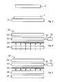
- the detector arrangement 10 shown in Fig. 4 which may be used as the detector arrangement 7 of Fig. 2 or Fig. 3 , comprises an optional top cover 11 which may be provided for the purpose of protecting the light conducting body 12 directly under the top cover 11 and/or for the purpose of reflecting light within the light conducting body 12 at the boundary surface between the top cover 11 and the light conducting body 12.
- the detector arrangement may comprise several layers which are stacked upon each other to form the main body of the detector arrangement.
- the main body comprises a layer formed by a light conducting body or by a plurality of light conducting bodies as well as a thermochromic layer comprising thermochromic material.
- thermochromic layer may differ and at least one optional cover may be present above the layer of light conducting body or bodies or below the thermochromic layer.
- orientation shown in Fig. 2 and Fig. 4 to 9 is optional.
- the detector arrangement may be adapted to detect an object having an elevated temperature which is located above the detector arrangement. Therefore, the thermochromic layer is located above the light conducting layer in case of the arrangement shown in Fig. 3 .
- Other embodiments and other orientations are also possible.
- the detector arrangement may be held at a position approximately halfway in between the primary side conductor assembly and the secondary side receiving device.
- thermochromic layer may be located on the side of the light conducting body facing the primary side conductor assembly and a second thermochromic layer may located on the side of the light conducting body facing the secondary side receiving device. Therefore, the detector arrangement is sensitive to hot bodies on either side of the detector arrangement. This detector arrangement could alternatively be oriented in the horizontal direction, so that hot object can be detected on the left hand side and the right hand side of the arrangement, for example.
- thermochromic layer 13 is arranged in between the light conducting body 12 and the bottom cover 14.
- At least one of the covers 11, 14 may be a thin layer (e.g. less than 1 mm thick) of polymer.
- the top cover 11 is not transparent for light, while the bottom cover 14 is transparent for light.
- the property of being transparent for light is indicated by several arrows pointing from the bottom to the top and extending through the bottom cover 14.
- a light conductor 16 such as a glass fibre cable is connected to one side of the light conducting body 12 so that light which is incident to the light conducting body ( Fig. 6 ) is conducted through the light conductor 16 to a light detector 15, which may be an array of photodiodes or may comprise a single photodiode.
- thermochromic layer 13 As shown in Fig. 6 , during operation while an object 18 having an elevated temperature is located below the detector arrangement 10, heat (as indicated by a double-line arrow) is transferred from the object 18 to the thermochromic layer 13 so that at least the area of the thermochromic layer 13 which faces the object 18 changes its state from opaque to transparent and the light from the ambience can pass through the thermochromic layer 13 and is incident on the light conducting body 12.
- the light conducting body may comprise light scattering material and/or fluorescent material so that scattered light and/or light produced by fluorescence is conducted by the light conductor 16 to the light detector 15.
- the side of the light conducting body 12 which is opposite to the light conductor 16 may be provided with material which reflects light so that the light which is received by the light detector 15 is increased.
- the second embodiment of a detector arrangement 20 shown in Fig. 5 also comprises an optional top cover 21 which can be omitted for example if the detector arrangement is directly attached to the underside of the secondary side receiving device (for example shown in Fig. 2 ).
- the detector arrangement 20 also comprises a light conducting body 22, a light conductor 26 and a light detector 25, which may have the same configuration as described before with reference to Fig. 4 and Fig. 6 .
- thermochromic layer 23 of detector arrangement 20 is arranged in between the light conducting body 22 and a light emitting device 24, which may be an array of organic light emitting diodes. It is preferred that the detector arrangement 20 comprises a bottom cover 27 made of material which is not transparent for light.
- the light emitting device 24 emits light toward the thermochromic layer 23. If a hot body 18 is present and, therefore, at least an area of the thermochromic layer 23 is transparent, light emitted by the light emitting device 24 passes through the thermochromic layer 23 as shown in Fig. 7 and is conducted by the light conducting body 22 and the light conductor 26 to the light detector 25.
- the detector arrangement 30 shown in Fig. 8 comprises a layer of at least two neighbouring light conducting bodies 32a, 32b, each of which is connected via a light conductor 16a, 16b to a light detector 15a, 15b. However, the boundary surface of the neighbouring light conducting bodies 32 is not transparent for light.
- a light reflecting material can be placed in between the light conducting bodies 32.
- the detector arrangement 30 can be constructed in the same manner as described above or below.
- the detector arrangement 30 comprises a light transparent bottom cover 34 and a single thermochromic layer 33 in between the bottom cover 34 and the layer of light conducting bodies 32.
- thermochromic layer 33 is transparent for light so that light from the ambience (or, alternatively, from a light emitting device of the detector arrangement) can pass through the thermochromic layer 33.
- the transparent area of the thermochromic layer 33 is located below the light conducting body 32b and there is no transparent area under the light conducting body 32a. Therefore, the second light detector 15b detects light indicating that there is a hot object 18 but the first light detector 15a does not detect such light.
- the location of the hot body 18 can be detected.
- the resolution of the location detection depends on the construction of the detector arrangement (especially it depends on the optical properties of the thermochromic layer and depends on the heat capacity and heat conductivity of any cover and other materials of the detector arrangement.
- the detector arrangement may comprise at least two light conducting bodies, wherein each light conducting body is coupled with a separate light detector.
- each light conducting body is coupled with a separate light detector.
- thermochromic layer 43 is realized by a cover layer.
- the detector arrangement 40 therefore comprises at least a light conducting body 42 and a cover 43 comprising thermochromic material.
- the light conducting body 42 is connected to a light detector 15 via a light conductor 16, similar to the arrangement shown in Fig. 4 and Fig. 6 .
- thermochromic material has become transparent. The light is conducted by the light conducting body 42 to the light conductor 16 and to the light detector 15.
Landscapes
- Engineering & Computer Science (AREA)
- Physics & Mathematics (AREA)
- General Physics & Mathematics (AREA)
- Power Engineering (AREA)
- Transportation (AREA)
- Mechanical Engineering (AREA)
- Life Sciences & Earth Sciences (AREA)
- General Life Sciences & Earth Sciences (AREA)
- Geophysics (AREA)
- Measuring Temperature Or Quantity Of Heat (AREA)
- Photometry And Measurement Of Optical Pulse Characteristics (AREA)
Abstract
● a light conducting body (12),
● a thermochromic layer (13) comprising thermochromic material adapted to change from an opaque state to a light transparent state with increasing temperature or vice versa, the thermochromic layer (13) being arranged in such a manner relative to the light conducting body (12) that light incident on the light conducting body (12) has to pass through the thermochromic layer (13) and
● a light detector (15) coupled with the light conducting body (12).
Description
- The invention relates to a detector arrangement for detecting an object having an elevated temperature. Furthermore, the invention relates to an arrangement for transferring energy from a primary side conductor assembly that produces an electromagnetic field, while an electric current flows through the conductor assembly, to a secondary side receiving device, that receives the electromagnetic field and produces an electric current by magnetic induction. In addition, the invention relates to a method of detecting an object having an elevated temperature. The invention also relates to a method of manufacturing a detector arrangement for detecting an object having an elevated temperature and to a method of manufacturing the transfer arrangement mentioned before.
-
WO 2010/031595 A2 discloses an arrangement for providing a vehicle, in particular a track bound vehicle, with electric energy, wherein the arrangement comprises a receiving device adapted to receive an alternating electromagnetic field and to produce an alternating electric current by electromagnetic induction. - The present invention can be applied in particular to the field of energy transfer to any land vehicle, in particular track bound vehicles, such as rail vehicles (e.g. trams), but also to road automobiles, such as individual (private) passenger cars or public transport vehicles (e.g. busses). Preferably, the primary side conductor arrangement of the generating device which produces the alternating electromagnetic filed is integrated in the track, road or parking area of the vehicle so that the electric lines of the primary side conductor arrangement extend in a plane which is nearly parallel to the surface of the road, track or parking area on which the vehicle may travel or may be parked.
- Unlike conventional transformers for transferring energy from a primary side to a secondary side, there is a gap between the primary side conductor assembly and the secondary side receiving device that receives the electromagnetic field produced by the conductor assembly. During operation of the arrangement, electrically conducting material may be present in the gap, such as metal coins. In this case, the electromagnetic field produced by the conductor assembly will induce electric currents (in particular eddy currents) in the material, the electric currents will be damped due to the electric resistance of the material and, as a result, the temperature of the material will increase. In particular in case of high transfer power (such as in the range of more than 10 kW, especially of more than 100 kW), which may happen while the electrochemical energy storage of a parked vehicle is charged, the temperature of such material may increase to some hundred degrees centigrade. After charging, the vehicle may move on and there is a significant risk that the hot material causes damage and injuries.
- It is therefore an object of the present invention to provide a detector arrangement for detecting an object having an elevated temperature, a transfer arrangement for transferring energy from a primary side conductor assembly to a secondary side receiving device, a method of detecting an object having an elevated temperature, a method of manufacturing the detector arrangement and the transfer arrangement, which reduce or eliminate the risk of damage and injuries. In particular, the detector arrangement shall be suited for being operated in connection with a transfer arrangement for transferring energy from a primary side conductor assembly to a secondary side receiving device.
- According to a basic concept of the invention, thermochromic substances are used to detect an object having an elevated temperature. The temperature of the object is elevated if it is higher than the ambience temperature, in particular the temperature of the ambience of a transfer arrangement for transferring energy from a primary side conductor assembly to a secondary side receiving device. Especially, the temperature is elevated if it is increased to a pre-determined minimum temperature or to a pre-determined range of temperatures. It is preferred that the thermochromic properties of the substance or substances correspond to the elevated temperature or to the range of temperatures which are elevated. In particular, a thermochromic substance or thermochromic substances are chosen and its properties or their properties allow for detection of objects having corresponding elevated temperature. The heat which is transferred from the object having an elevated temperature causes a change of the light transmitting properties of the thermochromic substance or substances.
- Generally speaking, thermochromic substances can change their colour due to a change in temperature. Therefore, for the purposes of the present invention, any thermochromic substance can be used in order to detect an object having an elevated temperature. As mentioned before, heat from the object is transferred to the thermochromic substance(s), in particular by radiation and/or by convection, and this causes a change in colour of the substance(s). Due to this change in colour, the thermochromic substance(s) has/have an opaque state, at least with reference to electromagnetic radiation in a specific range of wavelength. At other temperatures of the substance(s) it/they is/are no longer opaque with reference to the radiation at least within the mentioned range of wavelength.
- In specific embodiments, a change in colour means that the thermochromic substance(s) is/are opaque for radiation in a first range of wavelengths before the change and is opaque for radiation in a second, other range of wavelengths after the change. For example, the colour may change from blue to yellow or red with increasing temperature. However, the present invention is not restricted to specific colour changes and is not restricted to the wavelength range of radiation which is visible to humans. For example, the property of a thermochromic substance to be transparent for infrared radiation at specific temperatures can be used for the purposes of the present invention. However, it is preferred that light in the visible wavelength range, which has passed a layer comprising thermochromic material, is detected for the purposes of the present invention. Therefore, a corresponding light detector is used, preferably. In this description, "light" is used as a synonym for electromagnetic radiation. Light in the visible range is the radiation which is preferred for the purposes of the present invention. Moreover, it is preferred that the detection of light which has passed through the thermochromic material is not sensitive to specific colour ranges in the visible range of light. Therefore, it is preferred that the thermochromic material (i.e. the thermochromic substance or substances) is/are opaque for visible light in a first state (the "opaque state") at temperatures when there is no object having an elevated temperature, and is in a transparent state for visible light when there is an object having an elevated temperature. For example, the thermochromic material may be black (i.e. it absorbs light) or may be white (i.e. reflects all light) in the opaque state. In any case, it is preferred that the change of colour is reversible, e.g. the opaque material can change its colour with increasing temperature and can cool down again to its initial opaque state. Alternatively, the heat which is transferred from the object may change the thermochromic material from being transparent to being opaque.
- Thermochromic material in any available form can be used. For example, the thermochromic material may be a liquid crystal or a leuco dye or a mixture of leuco dyes. Especially leuco dyes can be used dispersed in a matrix of other material, in particular plastic material, such as thermoplastics, duroplastics, gels or other kind of plastic material. In particular, polymers are suitable as a matrix for carrying dispersed thermochromic material. Therefore, "matrix" is not to be understood having regular rows and columns. Rather, the matrix material only has the function of embedding the thermochromic material. Another form of using thermochromic material is an ink. Still another form is a lacquer. In both cases, the thermochromic material (in particular a leuco dye or mixture of dyes) is mixed with at least one other component of the ink or lacquer. As a result, the surface of a body made of other material can be coated with the ink or lacquer to form a layer comprising thermochromic material. Any liquid component of the ink or dye may dry, may be dried and/or may evaporate so that the coating hardens and forms a permanent solid layer comprising the thermochromic material. In addition or alternatively, the ink or lacquer may be cured, such as by using ultraviolet radiation. According to a further alternative, the ink or lacquer may be a mixture of at least two components additionally comprising the thermochromic material and the at least two components may form a compound during the time interval after applying the ink or lacquer on the surface or within a mould, thereby forming a layer or body of permanent shape. Still another form of using thermochromic material is a foil, for example a plastic film or plastic sheet, wherein the foil comprises the thermochromic substance(s).
- According to alternative embodiments of the invention, thermochromic material is used which is adapted to change from an opaque state to a light transparent state with decreasing temperature, i.e. heat from an object having an elevated temperature changes the state of the thermochromic material from the light transparent state to the opaque state.
- According to a further aspect of the invention, light which has passed through the thermochromic material in the light transparent state is detected by a light detector, which comprises at least one sensor that produces a signal if light is incident to the sensor. Therefore, the invention comprises embodiments, which comprise a light detector having sensors at different locations. In particular, the different sensors may be placed on different sides of a light conducting body and/or may be connected to a light conducting body via different light conductors (such as glass fibre cables).
- Depending on the properties of the thermochromic material mentioned above, the light detector either detects light when there is an object having an elevated temperature and, therefore, the thermochromic material is in the transparent state, or the light detector detects light when there is no object having an elevated temperature and, therefore, the thermochromic material is in the transparent state. For example, the sensor or sensors may be photodiode(s).
- In particular, the thermochromic material and a light conducting body are arranged in such a manner that light incident on the light conducting body has to pass through the thermochromic layer. Although preferred, this does not necessarily mean that all light which is incident on the light conducting body has to pass through the thermochromic layer. For example, the thermochromic layer may be arranged on one side of the light conducting body and other sides of the light conducting body may be covered by opaque material. Although not preferred, some light may pass though the opaque material to the light conducting body and/or some light may be incident on the light conducting body through gaps of the opaque material.
- The light detector is coupled with the light conducting body so that light which is incident on the light conducting body is conducted by the light conducting body to the light detector.
- In particular, the light conducting body may consist of a light transparent material which has a higher refractive index than neighbouring material, so that total reflection occurs. The use of a light conducting body has the advantage, that the light detector can be placed at a distance to the thermochromic material. Especially with respect to the transfer of electromagnetic energy to a vehicle, the light detector can be placed at a location where the flux density of the magnetic field is small (in particular smaller by a divisor of at least ten or preferably at least one hundred and most preferred at least one thousand) compared to the location of the highest magnetic flux density. Furthermore, the light conducting body in combination with the thermochromic material allows for a purely optical measurement procedure and is therefore independent of the electromagnetic or magnetic field.
- For example, in some of the embodiments and variants described above, it may happen that not all light which is incident on the light conducting body is conducted to the light detector. Furthermore, as mentioned above as well, some light may be incident on the light conducting body which has not passed through the thermochromic material. In order to reliably detect the transparent state of the thermochromic layer, it is preferred that it is decided that the thermochromic layer is in the transparent state if the light detector receives light having at least a predetermined minimum flux density (i.e. light intensity). According to an alternative embodiment, it is decided that the thermochromic layer is in the transparent state if the light detector receives light with a flux density within a predetermined range of possible flux densities (i.e. the minimum and the maximum value of the flux density is predetermined). For example, it may be decided that there is an error if the predetermined maximum flux density is exceeded. In any case, a predetermined minimum flux density guarantees that small flux densities are not recognized as indicating the transparent state. In the process of predetermining the minimum (and optionally also the maximum) flux density, typical illumination conditions and a typical object having a typical elevated temperature in an expected location relative to the thermochromic layer can be considered. In addition or alternatively, experiments can be made in order to set the predetermined value(s). The temperature of the object, the size of the object and the location of the object relative to the thermochromic material may influence the optical properties of the thermochromic material with respect to the amount of light per time interval which passes through the thermochromic material at a given illumination. Of course, increased illumination will result in an increased amount of light per time interval. In particular, larger objects and higher temperatures of the object or objects will lead to larger areas of the thermochromic material becoming transparent (or according to the alternative embodiment, becoming opaque).
- Preferably, the light conducting body comprises a side (e.g. defined by a surface of the light conducting body) which is to be oriented toward an area, in which an object having an elevated temperature may be placed.
- In particular, the following is proposed: A detector arrangement for detecting an object having an elevated temperature, the arrangement comprising:
- ● a light conducting body,
- ● a thermochromic layer comprising thermochromic material adapted to change from an opaque state to a light transparent state with increasing temperature or vice versa, the thermochromic layer being arranged in such a manner relative to the light conducting body that light incident on the light conducting body has to pass through the thermochromic layer and
- ● a light detector coupled with the light conducting body.
- In addition, a method is proposed of detecting an object having an elevated temperature, the method comprising:
- ● allowing light to pass through a thermochromic layer comprising thermochromic material, wherein heat from the object changes the state of the thermochromic material from an opaque state to a light transparent state or vice versa,
- ● receiving the light, which passed through the thermochromic layer, by a light conducting body,
- ● guiding the light within the light conducting body toward a light detector coupled with the light conducting body and
- ● detecting the light using the light detector, thereby detecting the presence or absence of the object having an elevated temperature.
- Furthermore, a method is proposed of manufacturing a detector arrangement for detecting an object having an elevated temperature, the method comprising:
- ● providing a light conducting body,
- ● arranging a thermochromic layer on at least one side of the light conducting body,
wherein the thermochromic layer is provided with thermochromic material adapted to change from an opaque state to a light transparent state with increasing temperature or vice versa and - ● coupling a light detector with the light conducting body.
- The thermochromic layer comprising thermochromic material may be in any of the forms mentioned above. In particular, the layer (which does not necessarily, but preferably, have a constant layer thickness) may be mechanically connected to the light conducting body. It is preferred that the thermochromic layer is a layer carried by and covering a surface of the light conducting body.
- According to a specific embodiment which has a particularly flat configuration which is able to detect objects having an elevated temperature in a wide area, the light conducting body is preferably shaped as a plate having a planar surface covered by the thermochromic layer. If an object having an elevated temperature is placed in the area which is faced by the thermochromic layer, the thermochromic layer will be heated and will either become transparent or opaque in the region facing the object.
- The light conducting body may be located on a first side of the thermochromic layer and a protective cover may be located on a second side, opposite to the first side, of the thermochromic layer. The protective cover protects the thermochromic layer from external influences, in particular mechanical damage by impacting parts. Optionally, the thermochromic layer may be in mechanical contact with the light conducting body and the protective cover, but there are other possible embodiments. The protective cover may form the outer surface of the arrangement which faces the area where objects having an elevated temperature can be detected.
- According to one embodiment, the cover is transparent for light. In this case, light from the ambience can pass through the cover and can also pass through the thermochromic layer, provided that the thermochromic layer or an area of the thermochromic layer is in the transparent state.
- An example of a protective cover is made from plastic material. The thickness of the protecting cover is preferably less than 3 mm, in particular less than 1 mm and most preferred less than 0.5 mm. A protective cover having a small thickness has two advantages. It does not significantly reduce the flux density of the passing light and it does not significantly contribute to the thermal capacity of the arrangement, i.e. heat emitted by an object can pass the protective cover.
- In any case, the thermochromic layer may be formed by the protective cover which covers the light conducting body on a first side, wherein the thermochromic material is dispersed in light transparent material of the protective cover. Therefore, there is no need for an additional protective cover. In particular, the protective cover may be a light transparent polymer.
- In particular, a light emitting device can be located beyond the thermochromic layer, if viewed from the light conducting body. For example, the light emitting device may be an array of light emitting diodes (LEDs). During operation of the arrangement, light emitted by the light emitting device can pass through the thermochromic layer, if the thermochromic layer is in the transparent state. Using a light emitting device has the advantages that the illumination of the thermochromic layer can be controlled and objects having an elevated temperature can be detected which are located in dark or shaded area. In addition, not only the amount of light, which is produced by the light emitting device per time interval, can be controlled, but also the amount of light per time interval as a function of time. For example, the intensity of the light can be increased, decreased or both according to a predetermined function of time and it can be decided that the thermochromic layer is in the transparent state only, if the same or a similar time-dependent behaviour is observed with the detection signal produced by the light detector which is coupled with the light conducting body. For example, the light emitted by the light emitting device can be pulsed at a predetermined pulse frequency.
- According to a specific embodiment, a protective cover which is opaque for light may be located beyond the light emitting device if viewed from the light conducting body. In this manner, the light emitting device can be mechanically protected and the detector arrangement can be shielded against light from the ambiance by the protective cover. Again, the components (here: the light emitting device and the protective cover) should be as thin as possible, so that heat from an object having an elevated temperature can pass though the cover and the light emitting device to the thermochromic layer. For example, the light emitting device may comprise OLEDs (organic light emitting diodes) and/or a thin plastic protective cover, for example made of a polymer.
- Furthermore, the following also belongs to the present invention: A transfer arrangement for transferring energy from a primary side conductor assembly, that produces an electromagnetic field while an electric current flows through the conductor assembly, to a secondary side receiving device, that receives the electromagnetic field and produces an electric current by magnetic induction, wherein the transfer arrangement comprises
- ● the primary side conductor assembly and/or the secondary side receiving device and
- ● the detector arrangement of one of the embodiments described above or below,
wherein the detector arrangement is located in an area through which the electromagnetic field extends during transfer of energy from the primary side conductor assembly to the secondary side receiving device. - For example, the primary side conductor assembly may be integrated in the track or the base (e.g. the ground) of a parking place of a vehicle and the vehicle may comprise the secondary side receiving device (e.g. at the underside of the vehicle facing downward), wherein the receiving device is placed above the primary side conductor assembly. Typically, there is a gap between the conductor assembly and the secondary side receiving device and the detector arrangement of the present invention is preferably placed in the gap. The gap includes any solid material in between the conductor assembly and the secondary side receiving device. Therefore, the detector arrangement can be integrated as well in the track, base or ground.
- Furthermore, the invention includes a method of manufacturing the transfer arrangement, comprising the steps:
- ● a primary side conductor assembly is provided, that produces an electromagnetic field while an electric current flows through the conductor assembly,
- ● a secondary side receiving device is provided, that receives the electromagnetic filed and produces an electric current by magnetic induction,
- ● the detector arrangement according to one embodiment described above or below is located in an area through which the electromagnetic field extends during transfer of energy from the primary side conductor assembly to the secondary side receiving device.
- Examples of the invention will be described with reference to the attached figures in the following. The figures show:
- Fig. 1
- schematically a side view of a primary side conductor assembly buried in the ground and a vehicle having a secondary side receiving device,
- Fig. 2
- schematically a side view of an arrangement comprising a primary side conductor assembly and a secondary side receiving device, wherein a detector arrangement for detecting the presence of an object having an elevated temperature is attached to the secondary side receiving device,
- Fig. 3
- an arrangement similar to the arrangement shown in
Fig. 2 , wherein the detector arrangement is attached to the primary side conductor assembly, - Fig. 4
- schematically an exploded side view of a detector arrangement,
- Fig. 5
- schematically an exploded side view of another detector arrangement,
- Fig. 6
- the detector arrangement of
Fig. 4 and an object having an elevated temperature, - Fig. 7
- the detector arrangement of
Fig. 5 and an object having an elevated temperature, - Fig. 8
- schematically an exploded side view of a further detector arrangement and an object having an elevated temperature, wherein the detector arrangement comprises a plurality of light conducting bodies, and
- Fig. 9
- schematically an exploded side view of still another detector arrangement and of an object having an elevated temperature.
- The vehicle 1 which is schematically shown in
Fig. 1 comprises a secondaryside receiving device 2 for receiving an electromagnetic field produced by a primaryside conductor assembly 3 which is buried in the ground. The surface of the ground is denoted by 4. For example, the vehicle 1 drives onwheels surface 4 of the ground. Alternatively, the wheels may roll on rails during operation, if the vehicle is a rail vehicle. - The primary
side conductor assembly 3 produces the electromagnetic field, for example while the vehicle is driving. Alternatively, the vehicle 1 may stop or may be parked while the electromagnetic field energy is transferred to the receivingdevice 2 of the vehicle. - Especially if the vehicle may drive during transfer of electromagnetic energy to its
receiving device 2, it is preferred that thedetector arrangement 7 of the present invention is attached to the receivingdevice 2, as shown inFig. 2 . However, the example shown inFig. 2 is not restricted to the use while the vehicle drives. - Alternatively, in particular if a vehicle is provided with electromagnetic energy while it stops or is parked, the
detector arrangement 7 may be attached to the primaryside conductor assembly 3 as shown inFig. 3 . Any vehicle, to which the secondaryside receiving device 2 is attached, is not shown inFig. 2 orFig. 3 . - The
detector arrangement 10 shown inFig. 4 , which may be used as thedetector arrangement 7 ofFig. 2 orFig. 3 , comprises an optionaltop cover 11 which may be provided for the purpose of protecting thelight conducting body 12 directly under thetop cover 11 and/or for the purpose of reflecting light within thelight conducting body 12 at the boundary surface between thetop cover 11 and thelight conducting body 12. As shown inFig. 4 and in further embodiments ofFig. 5 ,Fig. 8 and Fig. 9 , the detector arrangement may comprise several layers which are stacked upon each other to form the main body of the detector arrangement. In each case, the main body comprises a layer formed by a light conducting body or by a plurality of light conducting bodies as well as a thermochromic layer comprising thermochromic material. The form of the thermochromic layer may differ and at least one optional cover may be present above the layer of light conducting body or bodies or below the thermochromic layer. However, the orientation shown inFig. 2 andFig. 4 to 9 is optional. As for example shown inFig. 3 , the detector arrangement may be adapted to detect an object having an elevated temperature which is located above the detector arrangement. Therefore, the thermochromic layer is located above the light conducting layer in case of the arrangement shown inFig. 3 . Other embodiments and other orientations are also possible. For example, the detector arrangement may be held at a position approximately halfway in between the primary side conductor assembly and the secondary side receiving device. In this case, a first thermochromic layer may be located on the side of the light conducting body facing the primary side conductor assembly and a second thermochromic layer may located on the side of the light conducting body facing the secondary side receiving device. Therefore, the detector arrangement is sensitive to hot bodies on either side of the detector arrangement. This detector arrangement could alternatively be oriented in the horizontal direction, so that hot object can be detected on the left hand side and the right hand side of the arrangement, for example. - In case of the embodiment shown in
Fig. 4 , there is abottom cover 14 of light transparent material and thethermochromic layer 13 is arranged in between the light conductingbody 12 and thebottom cover 14. At least one of thecovers top cover 11 is not transparent for light, while thebottom cover 14 is transparent for light. The property of being transparent for light is indicated by several arrows pointing from the bottom to the top and extending through thebottom cover 14. - A
light conductor 16, such as a glass fibre cable is connected to one side of thelight conducting body 12 so that light which is incident to the light conducting body (Fig. 6 ) is conducted through thelight conductor 16 to alight detector 15, which may be an array of photodiodes or may comprise a single photodiode. - As shown in
Fig. 6 , during operation while anobject 18 having an elevated temperature is located below thedetector arrangement 10, heat (as indicated by a double-line arrow) is transferred from theobject 18 to thethermochromic layer 13 so that at least the area of thethermochromic layer 13 which faces theobject 18 changes its state from opaque to transparent and the light from the ambience can pass through thethermochromic layer 13 and is incident on thelight conducting body 12. - Optionally, and this does not apply to the embodiment shown in
Fig. 4 andFig. 6 only, the light conducting body may comprise light scattering material and/or fluorescent material so that scattered light and/or light produced by fluorescence is conducted by thelight conductor 16 to thelight detector 15. - Optionally, the side of the
light conducting body 12 which is opposite to thelight conductor 16 may be provided with material which reflects light so that the light which is received by thelight detector 15 is increased. - The second embodiment of a
detector arrangement 20 shown inFig. 5 also comprises an optionaltop cover 21 which can be omitted for example if the detector arrangement is directly attached to the underside of the secondary side receiving device (for example shown inFig. 2 ). Thedetector arrangement 20 also comprises alight conducting body 22, alight conductor 26 and alight detector 25, which may have the same configuration as described before with reference toFig. 4 andFig. 6 . - The
thermochromic layer 23 ofdetector arrangement 20 is arranged in between the light conductingbody 22 and alight emitting device 24, which may be an array of organic light emitting diodes. It is preferred that thedetector arrangement 20 comprises abottom cover 27 made of material which is not transparent for light. - During operation, the
light emitting device 24 emits light toward thethermochromic layer 23. If ahot body 18 is present and, therefore, at least an area of thethermochromic layer 23 is transparent, light emitted by thelight emitting device 24 passes through thethermochromic layer 23 as shown inFig. 7 and is conducted by thelight conducting body 22 and thelight conductor 26 to thelight detector 25. Thedetector arrangement 30 shown inFig. 8 comprises a layer of at least two neighbouringlight conducting bodies light conductor light detector - Otherwise, the
detector arrangement 30 can be constructed in the same manner as described above or below. In the exemplary embodiment shown inFig. 8 , thedetector arrangement 30 comprises a lighttransparent bottom cover 34 and a singlethermochromic layer 33 in between thebottom cover 34 and the layer of light conducting bodies 32. - During operation, while a
hot body 18 is present below thebottom cover 34, an area of thethermochromic layer 33 is transparent for light so that light from the ambience (or, alternatively, from a light emitting device of the detector arrangement) can pass through thethermochromic layer 33. In the specific operating state shown inFig. 8 , the transparent area of thethermochromic layer 33 is located below thelight conducting body 32b and there is no transparent area under thelight conducting body 32a. Therefore, the secondlight detector 15b detects light indicating that there is ahot object 18 but thefirst light detector 15a does not detect such light. - In this manner, the location of the
hot body 18 can be detected. The resolution of the location detection depends on the construction of the detector arrangement (especially it depends on the optical properties of the thermochromic layer and depends on the heat capacity and heat conductivity of any cover and other materials of the detector arrangement. - More generally speaking, the detector arrangement may comprise at least two light conducting bodies, wherein each light conducting body is coupled with a separate light detector. Preferably, there is a continuous thermochromic layer covering at least two of the light conducting bodies.
- According to the embodiment shown in
Fig. 9 , thethermochromic layer 43 is realized by a cover layer. Thedetector arrangement 40 therefore comprises at least alight conducting body 42 and acover 43 comprising thermochromic material. In the embodiment shown, thelight conducting body 42 is connected to alight detector 15 via alight conductor 16, similar to the arrangement shown inFig. 4 andFig. 6 . - If a
hot body 18 is present below thecover 43, light can pass through thecover 43 where the thermochromic material has become transparent. The light is conducted by thelight conducting body 42 to thelight conductor 16 and to thelight detector 15.
Claims (19)
- A detector arrangement (10; 20; 30; 40) for detecting an object (18) having an elevated temperature, the arrangement comprising:● a light conducting body (12; 22; 32a, 32b; 42),● a thermochromic layer (13; 23; 33; 43) comprising thermochromic material adapted to change from an opaque state to a light transparent state with increasing temperature or vice versa, the thermochromic layer (13; 23; 33; 43) being arranged in such a manner relative to the light conducting body (12; 22; 32a, 32b; 42) that light incident on the light conducting body (12; 22; 32a, 32b; 42) has to pass through the thermochromic layer (13; 23; 33; 43) and● a light detector (15; 25) coupled with the light conducting body (12; 22; 32a, 32b; 42).
- The detector arrangement of the preceding claim, wherein the thermochromic layer (13; 23; 33; 43) is mechanically connected to the light conducting body (12; 22; 32a, 32b; 42).
- The detector arrangement of the preceding claim, wherein the light conducting body (12; 22; 32a, 32b; 42) is shaped as a plate having a planar surface covered by the thermochromic layer (13; 23; 33; 43).
- The detector arrangement of one of the preceding claims, wherein the light conducting body (12; 22; 32a, 32b) is located on a first side of the thermochromic layer (13; 23; 33) and wherein a protective cover (14; 27; 34) is located on a second side, opposite to the first side, of the thermochromic layer (13; 23; 33).
- The detector arrangement of the preceding claim, wherein the cover (14; 34) is transparent for light.
- The detector arrangement of one of claims 1 - 3, wherein the thermochromic layer (43) is formed by a protective cover covering the light conducting body (42) on a first side and wherein the thermochromic material is dispersed in light transparent material of the protective cover.
- The detector arrangement of one of the preceding claims, wherein a light emitting device (24) of the detector arrangement (20) is located beyond the thermochromic layer (23) if viewed from the light conducting body (22).
- The detector arrangement of claim 7, wherein a protective cover (27) which is opaque for light is located beyond the light emitting device (24) if viewed from the light conducting body (22).
- A transfer arrangement for transferring energy from a primary side conductor assembly, that produces an electromagnetic field while an electric current flows through the conductor assembly, to a secondary side receiving device, that receives the electromagnetic field and produces an electric current by magnetic induction, wherein the transfer arrangement comprises● the primary side conductor assembly and/or the secondary side receiving device and● the detector arrangement(7) of one of the preceding claim
wherein the detector arrangement (7) is located in an area through which the electromagnetic field extends during transfer of energy from the primary side conductor assembly (3) to the secondary side receiving device (2). - A method of detecting an object having an elevated temperature, the method comprising:● allowing light to pass through a thermochromic layer (13; 23; 33; 43) comprising thermochromic material, wherein heat from the object changes the state of the thermochromic material from an opaque state to a light transparent state or vice versa,● receiving the light, which passed through the thermochromic layer (13; 23; 33; 43), by a light conducting body (12; 22; 32a, 32b; 42),● guiding the light within the light conducting body (12; 22; 32a, 32b; 42)toward a light detector (15; 25) coupled with the light conducting body (12; 22; 32a, 32b; 42) and● detecting the light using the light detector (15; 25), thereby detecting the presence or absence of the object having an elevated temperature.
- The method of claim 10, wherein the light or part of the light, which passes through the thermochromic layer (13; 33; 43), is light incident from the ambience.
- The method of claim 10 or 11, wherein the light or part of the light, which passes through the thermochromic layer (23), is light emitted by a light emitting device (24) located beyond the thermochromic layer (23) if viewed from the light conducting body (22).
- A method of manufacturing a detector arrangement (10; 20; 30; 40) for detecting an object (18) having an elevated temperature, the method comprising:● providing a light conducting body (12; 22; 32a, 32b; 42),● arranging a thermochromic layer (13; 23; 33; 43) on at least one side of the light conducting body (12; 22; 32a, 32b; 42), wherein the thermochromic layer (13; 23; 33; 43) is provided with thermochromic material adapted to change from an opaque state to a light transparent state with increasing temperature or vice versa and● coupling a light detector (15; 25) with the light conducting body (12; 22; 32a, 32b; 42).
- The method of the preceding claim, wherein the thermochromic layer (13; 23; 33; 43) is mechanically connected to the light conducting body (12; 22; 32a, 32b; 42).
- The method of claim 13 or 14, wherein the light conducting body (12; 22; 32a, 32b; 42) is shaped as a plate having a planar surface and the planar surface is covered by the thermochromic layer (13; 23; 33; 43).
- The method of one of claims 13 - 15, wherein the light conducting body (12; 22; 32a, 32b) is located on a first side of the thermochromic layer (13; 23; 33) and wherein a protective cover (14; 27; 34) is located on a second side, opposite to the first side, of the thermochromic layer (13; 23; 33).
- The method of one of claims 13 - 15, wherein the thermochromic layer (43) is formed by a protective cover covering the light conducting body (42) on a first side and wherein the thermochromic material is dispersed in light transparent material of the protective cover.
- The method of one of claims 13 - 17, wherein a light emitting device (24) of the arrangement is located beyond the thermochromic layer (23) if viewed from the light conducting body (22).
- The method of claim 18, wherein a protective cover (27) which is opaque for light is located beyond the light emitting device (24) if viewed from the light conducting body (22).
Applications Claiming Priority (1)
| Application Number | Priority Date | Filing Date | Title |
|---|---|---|---|
| GB1211314.8A GB2503451A (en) | 2012-06-25 | 2012-06-25 | Detecting an object having an elevated temperature |
Publications (2)
| Publication Number | Publication Date |
|---|---|
| EP2679970A2 true EP2679970A2 (en) | 2014-01-01 |
| EP2679970A3 EP2679970A3 (en) | 2015-08-26 |
Family
ID=46704228
Family Applications (1)
| Application Number | Title | Priority Date | Filing Date |
|---|---|---|---|
| EP13173444.4A Withdrawn EP2679970A3 (en) | 2012-06-25 | 2013-06-24 | Detecting an object having an elevated temperature |
Country Status (2)
| Country | Link |
|---|---|
| EP (1) | EP2679970A3 (en) |
| GB (1) | GB2503451A (en) |
Cited By (5)
| Publication number | Priority date | Publication date | Assignee | Title |
|---|---|---|---|---|
| WO2016169702A1 (en) * | 2015-04-21 | 2016-10-27 | Robert Bosch Gmbh | Battery system and method for monitoring a temperature of a battery system |
| US10444394B2 (en) | 2017-01-10 | 2019-10-15 | Witricity Corporation | Foreign object detection using heat sensitive material and inductive sensing |
| WO2020178797A1 (en) * | 2019-03-07 | 2020-09-10 | Te Connectivity Corporation | Isolated temperature sensing for electrical terminals |
| US12184087B2 (en) | 2022-02-03 | 2024-12-31 | Witricity Corporation | Foreign object detection using combined inductive and thermal sensing |
| US12609559B2 (en) | 2022-02-03 | 2026-04-21 | WiTricity AI Tech, LLC | Foreign object detection using hybrid inductive and capacitive sensing |
Family Cites Families (5)
| Publication number | Priority date | Publication date | Assignee | Title |
|---|---|---|---|---|
| FR2213493B1 (en) * | 1972-11-06 | 1975-04-25 | Onera (Off Nat Aerospatiale) | |
| GB2052731B (en) * | 1979-06-21 | 1983-10-19 | Spirig Ernst | Temperature responsive device |
| SU930023A1 (en) * | 1980-02-11 | 1982-05-23 | Предприятие П/Я Р-6891 | Device for measuring temperature |
| JPH07324994A (en) * | 1994-05-30 | 1995-12-12 | Sumitomo Wiring Syst Ltd | Temperature-detecting apparatus |
| US20110074346A1 (en) * | 2009-09-25 | 2011-03-31 | Hall Katherine L | Vehicle charger safety system and method |
-
2012
- 2012-06-25 GB GB1211314.8A patent/GB2503451A/en not_active Withdrawn
-
2013
- 2013-06-24 EP EP13173444.4A patent/EP2679970A3/en not_active Withdrawn
Cited By (13)
| Publication number | Priority date | Publication date | Assignee | Title |
|---|---|---|---|---|
| CN107534192B (en) * | 2015-04-21 | 2020-02-21 | 罗伯特·博世有限公司 | Battery system and method for monitoring the temperature of a battery system |
| CN107534192A (en) * | 2015-04-21 | 2018-01-02 | 罗伯特·博世有限公司 | The method of battery pack system and the temperature for monitoring battery pack system |
| US20180097264A1 (en) * | 2015-04-21 | 2018-04-05 | Robert Bosch Gmbh | Battery system and method for monitoring a temperature of a battery system |
| WO2016169702A1 (en) * | 2015-04-21 | 2016-10-27 | Robert Bosch Gmbh | Battery system and method for monitoring a temperature of a battery system |
| US11565596B2 (en) | 2017-01-10 | 2023-01-31 | Witricity Corporation | Foreign object detection using heat sensitive material and inductive sensing |
| US10444394B2 (en) | 2017-01-10 | 2019-10-15 | Witricity Corporation | Foreign object detection using heat sensitive material and inductive sensing |
| US11571976B2 (en) | 2017-01-10 | 2023-02-07 | Witricity Corporation | Foreign object detection using heat sensitive material and inductive sensing |
| US11945319B2 (en) | 2017-01-10 | 2024-04-02 | Witricity Corporation | Foreign object detection using heat sensitive material and inductive sensing |
| WO2020178797A1 (en) * | 2019-03-07 | 2020-09-10 | Te Connectivity Corporation | Isolated temperature sensing for electrical terminals |
| US11714008B2 (en) | 2019-03-07 | 2023-08-01 | Te Connectivity Solutions Gmbh | Isolated temperature sensing for hems contacts |
| US12066336B2 (en) | 2019-03-07 | 2024-08-20 | Te Connectivity Solutions Gmbh | Isolated temperature sensing for hems contacts |
| US12184087B2 (en) | 2022-02-03 | 2024-12-31 | Witricity Corporation | Foreign object detection using combined inductive and thermal sensing |
| US12609559B2 (en) | 2022-02-03 | 2026-04-21 | WiTricity AI Tech, LLC | Foreign object detection using hybrid inductive and capacitive sensing |
Also Published As
| Publication number | Publication date |
|---|---|
| EP2679970A3 (en) | 2015-08-26 |
| GB2503451A (en) | 2014-01-01 |
| GB201211314D0 (en) | 2012-08-08 |
Similar Documents
| Publication | Publication Date | Title |
|---|---|---|
| EP2679970A2 (en) | Detecting an object having an elevated temperature | |
| ES2706016T5 (en) | Disc assembly with electrically heated light scattering aperture | |
| US9028119B2 (en) | Light system having optic for use in a rearview mirror assembly | |
| US11485323B2 (en) | Imaging apparatus for vehicle | |
| CN106794747A (en) | The luminous vehicle window and the motor vehicles with this vehicle window of motor vehicles | |
| BR112012025699B1 (en) | LAMINATE STRUCTURE WITH BUILT-IN CAVITIES FOR USE WITH SOLAR CELLS AND RELATED MANUFACTURING METHOD | |
| CN101910520A (en) | reflector rod | |
| CN110609019A (en) | Fluorescence detection sensor | |
| CN115474431A (en) | Sheet assembly with heatable sensor window | |
| JP7263695B2 (en) | Optical element, light irradiation device | |
| JPS635489A (en) | Thermally readable surface characterizing array and method and apparatus for temperature activation thereof | |
| CN1133544C (en) | Printed matter detection device and printed matter detection method | |
| CN102661796A (en) | Active photoelectric marking method for MEMS infrared light supply array | |
| KR20120013382A (en) | Optical Detectors Used in Light Curtains | |
| KR102264369B1 (en) | Road safty indicating system having module type led lighting unit | |
| US10692912B2 (en) | Optical device for exposure of a sensor device for a vehicle | |
| JP6207359B2 (en) | Illumination device, image sensor unit, and paper sheet identification device | |
| KR102227822B1 (en) | Photocell sheet having visual transparency for absorbing infrared light | |
| EP3329309A1 (en) | Lighting device for optimized light distribution | |
| KR20140114469A (en) | Curing apparatus using ultraviolet | |
| CN104937703B (en) | Curing heat-curable materials in the embedded curing zone | |
| US10317286B2 (en) | Luminaire and method for temperature control | |
| EP2419887A1 (en) | Optical sensor for identifying and/or authenticating objects | |
| JP2025184669A (en) | Laminate and sensor system | |
| JP2018066212A (en) | Vehicle detector and attachment member installed on etc gate |
Legal Events
| Date | Code | Title | Description |
|---|---|---|---|
| PUAI | Public reference made under article 153(3) epc to a published international application that has entered the european phase |
Free format text: ORIGINAL CODE: 0009012 |
|
| AK | Designated contracting states |
Kind code of ref document: A2 Designated state(s): AL AT BE BG CH CY CZ DE DK EE ES FI FR GB GR HR HU IE IS IT LI LT LU LV MC MK MT NL NO PL PT RO RS SE SI SK SM TR |
|
| AX | Request for extension of the european patent |
Extension state: BA ME |
|
| PUAL | Search report despatched |
Free format text: ORIGINAL CODE: 0009013 |
|
| AK | Designated contracting states |
Kind code of ref document: A3 Designated state(s): AL AT BE BG CH CY CZ DE DK EE ES FI FR GB GR HR HU IE IS IT LI LT LU LV MC MK MT NL NO PL PT RO RS SE SI SK SM TR |
|
| AX | Request for extension of the european patent |
Extension state: BA ME |
|
| RIC1 | Information provided on ipc code assigned before grant |
Ipc: G01K 11/16 20060101AFI20150717BHEP |
|
| RAP1 | Party data changed (applicant data changed or rights of an application transferred) |
Owner name: BOMBARDIER PRIMOVE GMBH |
|
| STAA | Information on the status of an ep patent application or granted ep patent |
Free format text: STATUS: THE APPLICATION IS DEEMED TO BE WITHDRAWN |
|
| 18D | Application deemed to be withdrawn |
Effective date: 20160227 |