EP2679953A1 - Closed loop atomic inertial sensor - Google Patents
Closed loop atomic inertial sensor Download PDFInfo
- Publication number
- EP2679953A1 EP2679953A1 EP13171764.7A EP13171764A EP2679953A1 EP 2679953 A1 EP2679953 A1 EP 2679953A1 EP 13171764 A EP13171764 A EP 13171764A EP 2679953 A1 EP2679953 A1 EP 2679953A1
- Authority
- EP
- European Patent Office
- Prior art keywords
- frequency
- signal
- atomic
- mems
- inertial sensor
- Prior art date
- Legal status (The legal status is an assumption and is not a legal conclusion. Google has not performed a legal analysis and makes no representation as to the accuracy of the status listed.)
- Granted
Links
Images

Classifications
-
- G—PHYSICS
- G01—MEASURING; TESTING
- G01P—MEASURING LINEAR OR ANGULAR SPEED, ACCELERATION, DECELERATION, OR SHOCK; INDICATING PRESENCE, ABSENCE, OR DIRECTION, OF MOVEMENT
- G01P21/00—Testing or calibrating of apparatus or devices covered by the preceding groups
-
- G—PHYSICS
- G01—MEASURING; TESTING
- G01C—MEASURING DISTANCES, LEVELS OR BEARINGS; SURVEYING; NAVIGATION; GYROSCOPIC INSTRUMENTS; PHOTOGRAMMETRY OR VIDEOGRAMMETRY
- G01C19/00—Gyroscopes; Turn-sensitive devices using vibrating masses; Turn-sensitive devices without moving masses; Measuring angular rate using gyroscopic effects
- G01C19/58—Turn-sensitive devices without moving masses
-
- G—PHYSICS
- G01—MEASURING; TESTING
- G01C—MEASURING DISTANCES, LEVELS OR BEARINGS; SURVEYING; NAVIGATION; GYROSCOPIC INSTRUMENTS; PHOTOGRAMMETRY OR VIDEOGRAMMETRY
- G01C21/00—Navigation; Navigational instruments not provided for in groups G01C1/00 - G01C19/00
- G01C21/10—Navigation; Navigational instruments not provided for in groups G01C1/00 - G01C19/00 by using measurements of speed or acceleration
- G01C21/12—Navigation; Navigational instruments not provided for in groups G01C1/00 - G01C19/00 by using measurements of speed or acceleration executed aboard the object being navigated; Dead reckoning
- G01C21/16—Navigation; Navigational instruments not provided for in groups G01C1/00 - G01C19/00 by using measurements of speed or acceleration executed aboard the object being navigated; Dead reckoning by integrating acceleration or speed, i.e. inertial navigation
- G01C21/166—Mechanical, construction or arrangement details of inertial navigation systems
-
- G—PHYSICS
- G01—MEASURING; TESTING
- G01C—MEASURING DISTANCES, LEVELS OR BEARINGS; SURVEYING; NAVIGATION; GYROSCOPIC INSTRUMENTS; PHOTOGRAMMETRY OR VIDEOGRAMMETRY
- G01C21/00—Navigation; Navigational instruments not provided for in groups G01C1/00 - G01C19/00
- G01C21/10—Navigation; Navigational instruments not provided for in groups G01C1/00 - G01C19/00 by using measurements of speed or acceleration
- G01C21/12—Navigation; Navigational instruments not provided for in groups G01C1/00 - G01C19/00 by using measurements of speed or acceleration executed aboard the object being navigated; Dead reckoning
- G01C21/16—Navigation; Navigational instruments not provided for in groups G01C1/00 - G01C19/00 by using measurements of speed or acceleration executed aboard the object being navigated; Dead reckoning by integrating acceleration or speed, i.e. inertial navigation
- G01C21/183—Compensation of inertial measurements, e.g. for temperature effects
-
- G—PHYSICS
- G01—MEASURING; TESTING
- G01P—MEASURING LINEAR OR ANGULAR SPEED, ACCELERATION, DECELERATION, OR SHOCK; INDICATING PRESENCE, ABSENCE, OR DIRECTION, OF MOVEMENT
- G01P15/00—Measuring acceleration; Measuring deceleration; Measuring shock, i.e. sudden change of acceleration
- G01P15/02—Measuring acceleration; Measuring deceleration; Measuring shock, i.e. sudden change of acceleration by making use of inertia forces using solid seismic masses
- G01P15/08—Measuring acceleration; Measuring deceleration; Measuring shock, i.e. sudden change of acceleration by making use of inertia forces using solid seismic masses with conversion into electric or magnetic values
- G01P15/093—Measuring acceleration; Measuring deceleration; Measuring shock, i.e. sudden change of acceleration by making use of inertia forces using solid seismic masses with conversion into electric or magnetic values by photoelectric pick-up
Definitions
- a class of inertial sensors based on atom interferometry use pulses of light to split, and later, recombine the quantum wavefunctions or wavefunction from a sample of cold thermal or quantum degenerate atoms (Bose-Einstein condensate). While split, the phases of the separate parts evolve independently, allowing the accumulation of a phase difference due to the presence of acceleration and/or rotation. When recombined, this phase difference is manifested by changes in the final quantum momentum state or internal state of each atom, or in the quantum degenerate atom cloud as a whole.
- one sensor scheme results in changes to the relative populations of two internal states of the atoms. These populations can be detected by, for example, shining resonant light on the atoms and detecting the scattered fluorescence.
- the relative populations of the two internal states vary sinusoidally as a function of the phase difference induced by inertial forces.
- the derivative of the relative population with respect to phase difference is approximated by acquiring population measurements at two different phases. At a peak in the relative population sinusoid, the derivative curve crosses zero. Near the zero crossing of the derivative, a small change in phase will induce a large change in the derivative signal. Near a peak of the derivative, however, a small change in phase will induce only a very small change in derivative signal. It is therefore desirable to operate the atomic inertial sensor near a zero crossing or null point of the derivative signal, where sensitivity is maximized.
- a common technique to maintain operation near a null point is to provide closed loop feedback.
- the sensor output is compared to zero, or some other desired operating point.
- the difference between an open loop output and a setpoint is the error signal.
- the error signal is fed back to a mechanism on the sensor that forces the sensor to shift its output closer to the setpoint.
- the apparatus comprises at least one atomic inertial sensor, and one or more micro-electrical-mechanical systems (MEMS) inertial sensors operatively coupled to the atomic inertial sensor.
- MEMS micro-electrical-mechanical systems
- the atomic inertial sensor and the MEMS inertial sensors operatively communicate with each other in a closed feedback loop.
- Figure 2 is a block diagram of an apparatus for inertial sensing that provides closed loop control of an atomic inertial sensor according to one embodiment
- Figure 3 is a schematic diagram showing interferometer trajectory in a closed loop atomic inertial sensor according to another embodiment.
- the relative phase of the final recombination and readout optical pulse is shifted by using a locking circuit that locks to a master laser.
- the master laser provides a stable reference frequency. Other frequencies are shifted by some variable offset relative to the master laser.
- the optical phases of slave lasers are shifted until all of the atoms are found in the ground state. This produces a null signal if the detector is tuned to detect the derivative with respect to phase of the excited state population.
- the amount by which the optical phase must be tuned in order to maintain the null is used as the output signal, which can be related to a measure of delta rotation or delta velocity.
- Example 13 includes the apparatus of Example 12, wherein the first low pass filter sends a filtered signal to the first slave laser to adjust its frequency such that the second beam emitted by the first slave laser is at an adjusted frequency and is directed to a first input of the atomic inertial sensor.
Landscapes
- Engineering & Computer Science (AREA)
- Radar, Positioning & Navigation (AREA)
- Remote Sensing (AREA)
- Physics & Mathematics (AREA)
- General Physics & Mathematics (AREA)
- Automation & Control Theory (AREA)
- Gyroscopes (AREA)
- Navigation (AREA)
Abstract
Description
- This application claims the benefit of priority to United States Provisional Application No.
61/665,061, filed on June 27, 2012 - A class of inertial sensors based on atom interferometry use pulses of light to split, and later, recombine the quantum wavefunctions or wavefunction from a sample of cold thermal or quantum degenerate atoms (Bose-Einstein condensate). While split, the phases of the separate parts evolve independently, allowing the accumulation of a phase difference due to the presence of acceleration and/or rotation. When recombined, this phase difference is manifested by changes in the final quantum momentum state or internal state of each atom, or in the quantum degenerate atom cloud as a whole.
- For example, one sensor scheme results in changes to the relative populations of two internal states of the atoms. These populations can be detected by, for example, shining resonant light on the atoms and detecting the scattered fluorescence. The relative populations of the two internal states vary sinusoidally as a function of the phase difference induced by inertial forces. The derivative of the relative population with respect to phase difference is approximated by acquiring population measurements at two different phases. At a peak in the relative population sinusoid, the derivative curve crosses zero. Near the zero crossing of the derivative, a small change in phase will induce a large change in the derivative signal. Near a peak of the derivative, however, a small change in phase will induce only a very small change in derivative signal. It is therefore desirable to operate the atomic inertial sensor near a zero crossing or null point of the derivative signal, where sensitivity is maximized.
- There are many examples of sensors that are operated near a null point, in order to maximize sensitivity. A common technique to maintain operation near a null point is to provide closed loop feedback. In this technique, the sensor output is compared to zero, or some other desired operating point. The difference between an open loop output and a setpoint is the error signal. The error signal is fed back to a mechanism on the sensor that forces the sensor to shift its output closer to the setpoint.
- An apparatus for inertial sensing is provided. The apparatus comprises at least one atomic inertial sensor, and one or more micro-electrical-mechanical systems (MEMS) inertial sensors operatively coupled to the atomic inertial sensor. The atomic inertial sensor and the MEMS inertial sensors operatively communicate with each other in a closed feedback loop.
- Understanding that the drawings depict only exemplary embodiments and are not therefore to be considered limiting in scope, the exemplary embodiments will be described with additional specificity and detail through the use of the accompanying drawings, in which:
-
Figure 1 is a schematic diagram illustrating the ground states and excited states of atoms in a closed loop atomic inertial sensor according to one embodiment; -
Figure 2 is a block diagram of an apparatus for inertial sensing that provides closed loop control of an atomic inertial sensor according to one embodiment; and -
Figure 3 is a schematic diagram showing interferometer trajectory in a closed loop atomic inertial sensor according to another embodiment. - In the following detailed description, reference is made to the accompanying drawings that form a part hereof, and in which is shown by way of illustration specific illustrative embodiments. It is to be understood that other embodiments may be utilized and that logical, mechanical, and electrical changes may be made. Furthermore, the method presented in the drawing figures and the specification is not to be construed as limiting the order in which the individual steps may be performed. The following detailed description is, therefore, not to be taken in a limiting sense.
- A closed loop atomic inertial sensor is provided. A feedback technique is applied to the atomic inertial sensor to enhance sensor sensitivity. In one approach, phase shifting is employed in a closed loop feedback control to improve the sensitivity of the atomic inertial sensor.
- In one example, the relative phase of the final recombination and readout optical pulse is shifted by using a locking circuit that locks to a master laser. The master laser provides a stable reference frequency. Other frequencies are shifted by some variable offset relative to the master laser. The optical phases of slave lasers are shifted until all of the atoms are found in the ground state. This produces a null signal if the detector is tuned to detect the derivative with respect to phase of the excited state population. The amount by which the optical phase must be tuned in order to maintain the null is used as the output signal, which can be related to a measure of delta rotation or delta velocity.
- In one embodiment, direct inputs from MEMS vibratory sensors are used to null the phase readout of an atomic interferometer, enabling closed loop operation.
- Several physical mechanisms can be implemented for providing feedback to the atomic inertial sensor. In one embodiment, an external field can be applied to one arm of the interferometer, resulting in a control over the relative phase of the two interferometer arms. In another embodiment, a field gradient can be applied that provides a field differential between the two arms of the interferometer.
- In a further embodiment, shifting of the phase of one or more of the optical pulses that are used to recombine and read out the phase of the atomic wavefunctions or wavefunction is employed.
-
Figure 1 is a schematic diagram illustrating the ground states and excited states of atoms in a closed loop atomicinertial sensor 100 according to one embodiment, which uses three laser beam pulses. The following equation describes the operation of atomic inertial sensor 100:
where: - |c e|2 is the probability of finding the atom in the excited state after recombination;
- δ is the effective detuning of the laser light relative to the atomic transition;
- τ is the duration of an optical π pulse; and

- The pairs of parallel lines in
Figure 1 labeled A and B represent two possible quantum mechanical states of an atom. The atom begins instate 1. After the first optical pulse, depicted by the double ended arrow (φ1), the atom is in a superposition ofstates State 2 has additional momentum relative tostate 1, so half of the quantum wavefunction of the atom begins to move upward relative to the half of the wavefunction that remains instate 1. The parallelogram shows the trajectory of the two halves of the wavefunction as they move apart. After the second optical pulse (φ2), the states of the upper and lower halves of the wavefunction are reversed. Now the lower half is instate 2, and begins to move upward along the second half of the parallelogram until it eventually rejoins the first half. The final pulse (φ3) maps the accumulated phase difference onto the atomic state, so that the atom has a probability of ending in eitherstate 1 orstate 2, where that probability is proportional to the accumulated phase difference. - In an open loop operation, some fraction of the atoms wind up in the excited state, which provides a measure of accumulated phase difference that is proportional to inertial forces. In a closed loop operation, the feedback shifts the relative phase between the atoms and the optical pulses, which can be used to null the phase shift due to inertial forces.
- In one embodiment, a fusion of MEMS inertial sensors with one or more atomic inertial sensors is provided for closed loop control of the atomic inertial sensors in an integrated MEMS/atomic inertial sensing system.
-
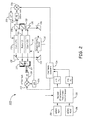
Figure 2 is a block diagram of anapparatus 200 for inertial sensing that provides closed loop control of an atomic inertial sensor according to one embodiment. Theapparatus 200 generally includes at least one atomicinertial sensor 202, and a plurality of micro electrical-mechanical systems (MEMS) inertial sensors, such as aMEMS gyroscope 204 and aMEMS accelerometer 206. The atomicinertial sensor 202 and the MEMS inertial sensors operatively communicate with each other in a closed feedback loop. - The
apparatus 200 also includes a plurality of laser devices, including amaster laser 210, afirst slave laser 212, and asecond slave laser 214, which are in optical communication with atomicinertial sensor 202. Themaster laser 210 is locked to a saturated absorption frequency (f) or an etalon (not shown). Thefirst slave laser 212 has a first shifted frequency (f1), and thesecond slave laser 214 has a second shifted frequency (f2). In one embodiment, the laser devices can be distributed Bragg reflector (DBR) laser diodes. In another embodiment, the laser devices include a vertical-cavity surface-emitting laser (VCSEL). - A beam from
master laser 210 and a beam fromslave laser 212 are directed by one or moreoptical components 215 such that the beams interfere with one another and generate a radio frequency (RF) signal at afirst photodetector 216 such as a photodiode (PD). In addition, the beam frommaster laser 210 and a beam fromslave laser 214 are directed by one or moreoptical components 217 such that the beams interfere with one another and generate an RF signal at asecond photodetector 218. - The atomic
inertial sensor 202, which exploits fundamental atomic physics to minimize drift, sequentially measures motion with respect to all three coordinate axes by selecting laser beam pairs that are oriented orthogonal (rotation) and parallel (acceleration) to those axes. Further details of an exemplary embodiment of the atomic inertial sensor can be found inU.S. Application Serial No. 13/661,809 , entitled MULTI-AXIS ATOMIC INERTIAL SENSOR SYSTEM, the disclosure of which is incorporated by reference. - The
MEMS gyroscope 204 andMEMS accelerometer 206 are operatively coupled to acalibration unit 220, which corrects MEMS bias and scale factor (SF) errors based on comparison of atomic data from atomicinertial sensor 202. Thecalibration unit 220 converts the rotation rate signal (Ω) received fromgyroscope 204 into a first frequency offset (Δf Ω), and converts the acceleration signal (α) received fromaccelerometer 206 into a second frequency offset (Δf α). The first and second frequency offsets are sent to afrequency sweep generator 224, which sends a frequency sweep signal to afirst mixer 226. Themixer 226 also receives the RF signal fromphotodetector 216. Themixer 226 compares the frequency sweep signal to the RF signal and provides a frequency offset lock signal that is sent to a low pass filter (LPF) 228. The filtered signal fromLPF 228 is sent toslave laser 212 to adjust its frequency. Theslave laser 212 emits a beam at the adjusted frequency that is directed to an input of atomicinertial sensor 202 by a pair ofreflectors 230. - The
sweep generator 224 also sends the frequency sweep signal to asecond mixer 232, which also receives the RF signal fromphotodetector 218. Themixer 232 compares the frequency sweep signal to the RF signal fromphotodetector 218 and provides a frequency offset lock signal that is sent to anLPF 234. The filtered signal fromLPF 234 is sent toslave laser 214 to adjust its frequency. Theslave laser 214 emits a beam at the adjusted frequency that is directed to an input of atomicinertial sensor 202 by a pair ofreflectors 236. - The frequency offsets applied to the
slave lasers -
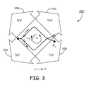
Figure 3 shows the interferometer trajectory in a closed loop atomicinertial sensor 300 according to another embodiment. The interferometer in atomicinertial sensor 300 is created by two counter-propagating laser beam pairs that intersect atoms and form a moving two-dimensional (2D) optical lattice that continuously sweeps to provide detuning. Relative detuning depends on location of the atoms. Two pairs ofcounter-propagating beams Figure 3 and accumulating phase. The atom clouds are then recombined. - The relative laser frequency (Δf) is the difference between the frequencies of the counter-propagating beams that perform interferometry in the atomic sensor. Detuning changes the sign. Detuning (Δf) depends on the x coordinate of the atom cloud and is defined by the following equation:

where: - Ω is rotation rate measured by the MEMS gyroscope;
- v is velocity measured by the MEMS accelerometer;
- c is velocity of light;
- f is average frequency = (f 1 + f 2)/2 = c/λ eff ; and
- λ eff is average wavelength of light.
- Example 1 includes an apparatus for inertial sensing, the apparatus comprising at least one atomic inertial sensor, and one or more micro-electrical-mechanical systems (MEMS) inertial sensors operatively coupled to the atomic inertial sensor. The atomic inertial sensor and the MEMS inertial sensors operatively communicate with each other in a closed feedback loop.
- Example 2 includes the apparatus of Example 1, wherein the atomic inertial sensor comprises an atomic interferometer.
- Example 3 includes the apparatus of any of Examples 1-2, wherein the MEMS inertial sensors comprise at least one MEMS gyroscope and at least one MEMS accelerometer.
- Example 4 includes the apparatus of any of Examples 1-3, further comprising a plurality of laser devices in optical communication with the atomic inertial sensor.
- Example 5 includes the apparatus of Example 4, wherein the laser devices comprise distributed Bragg reflector laser diodes or vertical-cavity surface-emitting lasers.
- Example 6 includes the apparatus of any of Examples 4-5, wherein the laser devices comprise a master laser that emits a first beam and a second beam, a first slave laser that emits a first beam and a second beam, and a second slave laser that emits a first beam and a second beam.
- Example 7 includes the apparatus of Example 6, further comprising one or more optical components that direct the first beam from the master laser and the first beam from the first slave laser to interfere with one another and generate a first radio frequency signal at a first photodetector.
- Example 8 includes the apparatus of any of Examples 6-7, further comprising one or more optical components that direct the second beam from the master laser and the first beam from the second slave laser to interfere with one another and generate a second radio frequency signal at a second photodetector.
- Example 9 includes the apparatus of any of Examples 3-8, wherein the MEMS gyroscope and the MEMS accelerometer are each operatively coupled to a calibration unit that corrects for MEMS bias and scale factor errors based on a comparison of atomic data from the atomic inertial sensor.
- Example 10 includes the apparatus of Example 9, wherein the calibration unit converts a rotation rate signal received from the MEMS gyroscope into a first frequency offset, and converts an acceleration signal received from the MEMS accelerometer into a second frequency offset.
- Example 11 includes the apparatus of Example 10, further comprising a frequency sweep generator that receives the first and second frequency offsets from the calibration unit.
- Example 12 includes the apparatus of Example 11, further comprising a first mixer that receives a first frequency sweep signal from the frequency sweep generator and receives the first radio frequency signal from the first photodetector, wherein the first mixer compares the first frequency sweep signal to the first radio frequency signal and generates a frequency offset lock signal that is sent to a first low pass filter.
- Example 13 includes the apparatus of Example 12, wherein the first low pass filter sends a filtered signal to the first slave laser to adjust its frequency such that the second beam emitted by the first slave laser is at an adjusted frequency and is directed to a first input of the atomic inertial sensor.
- Example 14 includes the apparatus of any of Examples 11-13, further comprising a second mixer that receives a second frequency sweep signal from the frequency sweep generator and receives the second radio frequency signal from the second photodetector, wherein the second mixer compares the second frequency sweep signal to the second radio frequency signal and generates a frequency offset lock signal that is sent to a second low pass filter.
- Example 15 includes the apparatus of Example 14, wherein the second low pass filter sends a filtered signal to the second slave laser to adjust its frequency such that the second beam emitted by the second slave laser is at an adjusted frequency and is directed to a second input of the atomic inertial sensor.
- Example 16 includes a method for inertial sensing that comprises providing an inertial sensing apparatus comprising at least one atomic inertial sensor, and a plurality of MEMS inertial sensors in operative communication with the atomic inertial sensor, the MEMS inertial sensors comprising at least one MEMS gyroscope and at least one MEMS accelerometer, wherein the atomic inertial sensor and the MEMS inertial sensors operatively communicate with each other in a closed feedback loop. The method further comprises directing a first beam from a master laser and a first beam from a first slave laser to interfere with one another and generate a first radio frequency signal; directing a second beam from the master laser and a first beam from a second slave laser to interfere with one another and generate a second radio frequency signal; converting a rotation rate signal received from the MEMS gyroscope into a first frequency offset; converting an acceleration signal received from the MEMS accelerometer into a second frequency offset; generating a frequency sweep signal from the first and second frequency offsets; comparing the frequency sweep signal to the first radio frequency signal to generate a first frequency offset lock signal; comparing the frequency sweep signal to the second radio frequency signal to generate a second frequency offset lock signal; sending the first frequency offset lock signal to the first slave laser to adjust its frequency such that the first slave laser emits a second beam at an adjusted frequency that is directed to the atomic inertial sensor; and sending the second frequency offset lock signal to the second slave laser to adjust its frequency such that the second slave laser emits a second beam at an adjusted frequency that is directed to the atomic inertial sensor.
- Example 17 includes the method of Example 16, wherein the atomic inertial sensor comprises an atomic interferometer.
- Example 18 includes the method of any of Examples 16-17, further comprising correcting outputs of the MEMS gyroscope and MEMS accelerometer for MEMS bias and scale factor errors based on a comparison of atomic data from the atomic inertial sensor.
- Example 19 includes an inertial sensing apparatus that comprises at least one atomic inertial sensor comprising an atomic interferometer, a plurality of MEMS inertial sensors in operative communication with the atomic inertial sensor, the MEMS inertial sensors comprising at least one MEMS gyroscope and at least one MEMS accelerometer, and a plurality of laser devices in optical communication with the atomic inertial sensor. The atomic inertial sensor and the MEMS inertial sensors operatively communicate with each other in a closed feedback loop.
- Example 20 includes the apparatus of Example 19, further comprising a calibration unit operatively coupled to the MEMS gyroscope and the MEMS accelerometer, the calibration unit configured to correct for MEMS bias and scale factor errors based on a comparison of atomic data from the atomic inertial sensor.
- Although specific embodiments have been illustrated and described herein, it will be appreciated by those of ordinary skill in the art that any arrangement, which is calculated to achieve the same purpose, may be substituted for the specific embodiments shown. Therefore, it is manifestly intended that this invention be limited only by the claims and the equivalents thereof.
Claims (10)
- An apparatus for inertial sensing, the apparatus comprising:at least one atomic inertial sensor; andone or more micro-electrical-mechanical systems (MEMS) inertial sensors operatively coupled to the atomic inertial sensor;wherein the atomic inertial sensor and the MEMS inertial sensors operatively communicate with each other in a closed feedback loop.
- The apparatus of claim 1, wherein the atomic inertial sensor comprises an atomic interferometer.
- The apparatus of claim 1, wherein the MEMS inertial sensors comprise at least one MEMS gyroscope and at least one MEMS accelerometer.
- The apparatus of claim 3, further comprising a plurality of laser devices in optical communication with the atomic inertial sensor, wherein the laser devices comprise:a master laser that emits a first beam and a second beam;a first slave laser that emits a first beam and a second beam; anda second slave laser that emits a first beam and a second beam.
- The apparatus of claim 4, further comprising:one or more optical components that direct the first beam from the master laser and the first beam from the first slave laser to interfere with one another and generate a first radio frequency signal at a first photodetector; andone or more optical components that direct the second beam from the master laser and the first beam from the second slave laser to interfere with one another and generate a second radio frequency signal at a second photodetector.
- The apparatus of claim 5, wherein the MEMS gyroscope and the MEMS accelerometer are each operatively coupled to a calibration unit that corrects for MEMS bias and scale factor errors based on a comparison of atomic data from the atomic inertial sensor, wherein the calibration unit converts a rotation rate signal received from the MEMS gyroscope into a first frequency offset, and converts an acceleration signal received from the MEMS accelerometer into a second frequency offset.
- The apparatus of claim 6, further comprising:a frequency sweep generator that receives the first and second frequency offsets from the calibration unit;a first mixer that receives a first frequency sweep signal from the frequency sweep generator and receives the first radio frequency signal from the first photodetector, wherein the first mixer compares the first frequency sweep signal to the first radio frequency signal and generates a frequency offset lock signal that is sent to a first low pass filter, wherein the first low pass filter sends a filtered signal to the first slave laser to adjust its frequency such that the second beam emitted by the first slave laser is at an adjusted frequency and is directed to a first input of the atomic inertial sensor;a second mixer that receives a second frequency sweep signal from the frequency sweep generator and receives the second radio frequency signal from the second photodetector, wherein the second mixer compares the second frequency sweep signal to the second radio frequency signal and generates a frequency offset lock signal that is sent to a second low pass filter, wherein the second low pass filter sends a filtered signal to the second slave laser to adjust its frequency such that the second beam emitted by the second slave laser is at an adjusted frequency and is directed to a second input of the atomic inertial sensor.
- A method for inertial sensing, the method comprising:providing an inertial sensing apparatus comprising:at least one atomic inertial sensor; anda plurality of micro-electrical-mechanical systems (MEMS) inertial sensors in operative communication with the atomic inertial sensor, the MEMS inertial sensors comprising at least one MEMS gyroscope and at least one MEMS accelerometer;wherein the atomic inertial sensor and the MEMS inertial sensors operatively communicate with each other in a closed feedback loop;directing a first beam from a master laser and a first beam from a first slave laser to interfere with one another and generate a first radio frequency signal;directing a second beam from the master laser and a first beam from a second slave laser to interfere with one another and generate a second radio frequency signal;converting a rotation rate signal received from the MEMS gyroscope into a first frequency offset;converting an acceleration signal received from the MEMS accelerometer into a second frequency offset;generating a frequency sweep signal from the first and second frequency offsets;comparing the frequency sweep signal to the first radio frequency signal to generate a first frequency offset lock signal;comparing the frequency sweep signal to the second radio frequency signal to generate a second frequency offset lock signal;sending the first frequency offset lock signal to the first slave laser to adjust its frequency such that the first slave laser emits a second beam at an adjusted frequency that is directed to the atomic inertial sensor; andsending the second frequency offset lock signal to the second slave laser to adjust its frequency such that the second slave laser emits a second beam at an adjusted frequency that is directed to the atomic inertial sensor.
- The method of claim 8, wherein the atomic inertial sensor comprises an atomic interferometer.
- The method of claim 8, further comprising correcting outputs of the MEMS gyroscope and MEMS accelerometer for MEMS bias and scale factor errors based on a comparison of atomic data from the atomic inertial sensor.
Applications Claiming Priority (2)
| Application Number | Priority Date | Filing Date | Title |
|---|---|---|---|
| US201261665061P | 2012-06-27 | 2012-06-27 | |
| US13/758,370 US9030655B2 (en) | 2012-06-27 | 2013-02-04 | Closed loop atomic inertial sensor |
Publications (2)
| Publication Number | Publication Date |
|---|---|
| EP2679953A1 true EP2679953A1 (en) | 2014-01-01 |
| EP2679953B1 EP2679953B1 (en) | 2020-03-04 |
Family
ID=48651888
Family Applications (1)
| Application Number | Title | Priority Date | Filing Date |
|---|---|---|---|
| EP13171764.7A Active EP2679953B1 (en) | 2012-06-27 | 2013-06-12 | Closed loop atomic inertial sensor |
Country Status (4)
| Country | Link |
|---|---|
| US (1) | US9030655B2 (en) |
| EP (1) | EP2679953B1 (en) |
| JP (1) | JP2014029325A (en) |
| CN (1) | CN103512568A (en) |
Cited By (3)
| Publication number | Priority date | Publication date | Assignee | Title |
|---|---|---|---|---|
| FR3031187A1 (en) * | 2014-12-30 | 2016-07-01 | Thales Sa | COLD ATOMIC HYBRID INERTIA SENSOR AND MEMS AND ASSOCIATED INERTIAL PLANT |
| EP3290862A1 (en) * | 2016-09-02 | 2018-03-07 | Honeywell International Inc. | Fully reciprocal atomic interferometric gyroscope |
| CN116324426A (en) * | 2020-10-08 | 2023-06-23 | 日本航空电子工业株式会社 | Inertial sensor, atom interferometer, method for adjusting velocity and path of travel of atoms, device for adjusting velocity and path of travel of atomic beam |
Families Citing this family (27)
| Publication number | Priority date | Publication date | Assignee | Title |
|---|---|---|---|---|
| US8941053B1 (en) * | 2011-09-28 | 2015-01-27 | Sandia Corporation | High data-rate atom interferometers through high recapture efficiency |
| US9423272B2 (en) * | 2012-02-17 | 2016-08-23 | Honeywell International Inc. | Estimation of conventional inertial sensor errors with atomic inertial sensor |
| US8860933B2 (en) * | 2012-07-12 | 2014-10-14 | Honeywell International Inc. | Multi-axis atomic inertial sensor system |
| US9291508B1 (en) * | 2013-03-13 | 2016-03-22 | Sandia Corporation | Light-pulse atom interferometric device |
| US9568316B2 (en) * | 2013-03-15 | 2017-02-14 | The Charles Stark Draper Laboratory, Inc. | Ring architecture for sequential operation of an atomic gyroscope |
| US9618362B2 (en) * | 2014-06-03 | 2017-04-11 | Northrop Grumman Systems Corporation | Self-calibrating nuclear magnetic resonance (NMR) gyroscope system |
| US9175960B1 (en) | 2014-09-10 | 2015-11-03 | Honeywell International Inc. | Optically dithered atomic gyro-compass |
| US10330697B2 (en) | 2015-05-15 | 2019-06-25 | Honeywell International Inc. | Active, in-situ, calibration of MEMS accelerometers using optical forces |
| US9874581B2 (en) | 2015-05-15 | 2018-01-23 | Honeywell International Inc. | In-situ bias correction for MEMS accelerometers |
| US9983225B2 (en) | 2015-06-29 | 2018-05-29 | Honeywell International Inc. | Optical-mechanical vibrating beam accelerometer |
| FR3044398B1 (en) * | 2015-11-27 | 2019-07-19 | Thales | LASER SOURCE FOR COLD ATOMIC INERTIAL SENSOR |
| US9887019B2 (en) * | 2016-02-04 | 2018-02-06 | Honeywell International Inc. | Systems and methods for eliminating multi-path errors from atomic inertial sensors |
| US9952154B2 (en) * | 2016-06-22 | 2018-04-24 | The Charles Stark Draper Laboratory, Inc. | Separated parallel beam generation for atom interferometry |
| US10157692B2 (en) | 2016-06-22 | 2018-12-18 | The Charles Stark Draper Laboratory, Inc. | Cold atom interferometry |
| WO2018017898A1 (en) * | 2016-07-20 | 2018-01-25 | Urban626, Llc | Convertible scooter |
| CN106525019B (en) * | 2016-11-24 | 2023-07-25 | 华中科技大学 | Dual internal state Bragg atom interference inertial sensor |
| US11150093B1 (en) * | 2017-01-25 | 2021-10-19 | AOSense, Inc. | Inertial navigation system design for precision mobile reference platforms |
| WO2019241544A1 (en) * | 2018-06-15 | 2019-12-19 | Sri International | Atom chip for ultracold atom preparation and loading into an integrated optical waveguide evanescent field trap |
| US10816569B2 (en) | 2018-09-07 | 2020-10-27 | Analog Devices, Inc. | Z axis accelerometer using variable vertical gaps |
| US11255873B2 (en) | 2018-09-12 | 2022-02-22 | Analog Devices, Inc. | Increased sensitivity z-axis accelerometer |
| WO2020142140A1 (en) | 2019-01-02 | 2020-07-09 | Kutztown University Of Pennsylvania | Rotation sensing and magnetometry using localization on a ring shaped lattice |
| US11133117B2 (en) * | 2019-05-08 | 2021-09-28 | Northrop Grumman Systems Corporation | Atomic interferometer system |
| EP3983829B1 (en) * | 2019-06-13 | 2024-12-18 | University of Southampton | Quantum gravimeters and gradiometers |
| US12038285B1 (en) * | 2020-08-31 | 2024-07-16 | National Technology & Engineering Solutions Of Sandia, Llc | Hybrid inertial navigation system and method |
| US12449256B1 (en) * | 2020-11-04 | 2025-10-21 | National Technology & Engineering Solutions Of Sandia, Llc | Compact grating magneto-optical trap sensor head for inertial navigation in dynamic environments |
| FR3123980B1 (en) * | 2021-06-10 | 2023-06-30 | Thales Sa | ATOMIC CHIP WITH TWO CONDUCTIVE STRIPS FOR INERTIAL SENSOR WITH ULTRAFID ATOM AND ASSOCIATED SENSOR |
| US12359919B2 (en) | 2023-03-28 | 2025-07-15 | Honeywell International Inc. | High-contrast atomic inertial interferometry with frequency comb or comb-like light source |
Citations (3)
| Publication number | Priority date | Publication date | Assignee | Title |
|---|---|---|---|---|
| WO2007002327A1 (en) * | 2005-06-22 | 2007-01-04 | Litton Systems, Inc. | Method for combining continuous and discontinuous inertial instrument measurements and inertial navigation system using the same |
| US20100149541A1 (en) * | 2008-12-17 | 2010-06-17 | Lockheed Martin Corporation | Performance of an Atom Interferometric Device through Complementary Filtering |
| EP2629303A1 (en) * | 2012-02-17 | 2013-08-21 | Honeywell International Inc. | Atom interferometer with adaptive launch direction and/or position |
Family Cites Families (23)
| Publication number | Priority date | Publication date | Assignee | Title |
|---|---|---|---|---|
| US3761721A (en) | 1972-07-06 | 1973-09-25 | Trw Inc | Matter wave interferometric apparatus |
| US4545242A (en) * | 1982-10-27 | 1985-10-08 | Schlumberger Technology Corporation | Method and apparatus for measuring the depth of a tool in a borehole |
| US4992656A (en) | 1987-10-26 | 1991-02-12 | Clauser John F | Rotation, acceleration, and gravity sensors using quantum-mechanical matter-wave interferometry with neutral atoms and molecules |
| US5052808A (en) | 1990-02-15 | 1991-10-01 | Litton Systems, Inc. | Method and apparatus for interferometric rotation sensor phase modulation, intensity demodulation, and control |
| FR2675900B1 (en) | 1991-04-26 | 1995-12-01 | Alsthom Cge Alcatel | OPTICAL FIBER VIBRATION SENSOR AND ACCELEROMETER USING SAME. |
| US5274231A (en) | 1992-04-14 | 1993-12-28 | Board Of Trustees, Leland Stanford Jr. University | Method and apparatus for manipulating atoms, ions or molecules and for measuring physical quantities using stimulated Raman transitions |
| US6647352B1 (en) | 1998-06-05 | 2003-11-11 | Crossbow Technology | Dynamic attitude measurement method and apparatus |
| US6456939B1 (en) * | 2000-01-04 | 2002-09-24 | Mccall Hiram | Micro inertial measurement unit |
| DE10031542B4 (en) | 2000-06-28 | 2005-02-17 | Eads Astrium Gmbh | Inertial sensor for storing and controlling an inertial reference in a satellite |
| US6697736B2 (en) | 2002-02-06 | 2004-02-24 | American Gnc Corporation | Positioning and navigation method and system thereof |
| DE602004029253D1 (en) | 2003-07-03 | 2010-11-04 | Northrop Grummann Corp | METHOD AND DEVICE FOR INCREASING THE INERTIALIZED HEAVY GRADIENT |
| US7248964B2 (en) | 2003-12-05 | 2007-07-24 | Honeywell International Inc. | System and method for using multiple aiding sensors in a deeply integrated navigation system |
| EP1856691B1 (en) | 2005-02-01 | 2011-10-05 | The Board of Trustees of The Leland Stanford Junior University | Kinematic sensors employing atom interferometer phases |
| US7728587B2 (en) | 2007-07-31 | 2010-06-01 | Northrop Grumman Guidance And Electronics Company, Inc. | Self-calibrating nuclear magnetic resonance gyro |
| US7667644B2 (en) | 2007-10-09 | 2010-02-23 | Honeywell International Inc. | GPS receiver RAIM with slaved precision clock |
| FR2928725B1 (en) * | 2008-03-12 | 2010-04-09 | Centre Nat Rech Scient | COLD ATOMIC INTERFEROMETRIC SENSOR |
| EP2104406B1 (en) | 2008-03-19 | 2015-08-12 | Ixblue | Guided coherent atom source and atomic interferometer including the same |
| US7995630B2 (en) * | 2008-04-01 | 2011-08-09 | Rakuljic George A | High performance tunable lasers utilizing optical phase-locked loops |
| US8347711B2 (en) | 2008-09-15 | 2013-01-08 | Lockheed Martin Corporation | Atom-interferometric, stepped gravity gradient measuring system |
| IT1397594B1 (en) | 2009-12-21 | 2013-01-16 | St Microelectronics Rousset | MICROELETTROMECHANICAL GYROSCOPE WITH CONTINUOUS SELF-TEST FUNCTION AND METHOD OF CONTROL OF A MICROELECTRANOMIC GYROSCOPE. |
| US8583371B1 (en) | 2010-12-23 | 2013-11-12 | Lockheed Martin Corporation | Autonomous gyro temperature calibration |
| US8907276B2 (en) * | 2012-04-11 | 2014-12-09 | Honeywell International Inc. | Measuring the populations in each hyperfine ground state of alkali atoms in a vapor cell while limiting the contribution of the background vapor |
| US8860933B2 (en) * | 2012-07-12 | 2014-10-14 | Honeywell International Inc. | Multi-axis atomic inertial sensor system |
-
2013
- 2013-02-04 US US13/758,370 patent/US9030655B2/en active Active
- 2013-06-12 EP EP13171764.7A patent/EP2679953B1/en active Active
- 2013-06-17 JP JP2013126602A patent/JP2014029325A/en not_active Ceased
- 2013-06-26 CN CN201310258666.2A patent/CN103512568A/en active Pending
Patent Citations (3)
| Publication number | Priority date | Publication date | Assignee | Title |
|---|---|---|---|---|
| WO2007002327A1 (en) * | 2005-06-22 | 2007-01-04 | Litton Systems, Inc. | Method for combining continuous and discontinuous inertial instrument measurements and inertial navigation system using the same |
| US20100149541A1 (en) * | 2008-12-17 | 2010-06-17 | Lockheed Martin Corporation | Performance of an Atom Interferometric Device through Complementary Filtering |
| EP2629303A1 (en) * | 2012-02-17 | 2013-08-21 | Honeywell International Inc. | Atom interferometer with adaptive launch direction and/or position |
Non-Patent Citations (1)
| Title |
|---|
| YOUNG ET AL.: "Atom Interferometry", 1997, ACADEMIC PRESS, article "Precision Atom Interferometry with Light Pulses" |
Cited By (5)
| Publication number | Priority date | Publication date | Assignee | Title |
|---|---|---|---|---|
| FR3031187A1 (en) * | 2014-12-30 | 2016-07-01 | Thales Sa | COLD ATOMIC HYBRID INERTIA SENSOR AND MEMS AND ASSOCIATED INERTIAL PLANT |
| WO2016107806A1 (en) * | 2014-12-30 | 2016-07-07 | Thales | Hybrid inertia sensor employing cold atoms and mems and associated inertial platform |
| EP3290862A1 (en) * | 2016-09-02 | 2018-03-07 | Honeywell International Inc. | Fully reciprocal atomic interferometric gyroscope |
| US10352702B2 (en) | 2016-09-02 | 2019-07-16 | Honeywell International Inc. | Fully reciprocal atomic interferometric gyroscope |
| CN116324426A (en) * | 2020-10-08 | 2023-06-23 | 日本航空电子工业株式会社 | Inertial sensor, atom interferometer, method for adjusting velocity and path of travel of atoms, device for adjusting velocity and path of travel of atomic beam |
Also Published As
| Publication number | Publication date |
|---|---|
| CN103512568A (en) | 2014-01-15 |
| US9030655B2 (en) | 2015-05-12 |
| EP2679953B1 (en) | 2020-03-04 |
| US20140022534A1 (en) | 2014-01-23 |
| JP2014029325A (en) | 2014-02-13 |
Similar Documents
| Publication | Publication Date | Title |
|---|---|---|
| EP2679953B1 (en) | Closed loop atomic inertial sensor | |
| EP3333543B1 (en) | Multi-axis atomic inertial sensor system | |
| US11175139B2 (en) | Hybrid inertial measurement system and method using a light pulse cold atom interferometer | |
| JP5798639B2 (en) | Atomic beam gyroscope | |
| US9291508B1 (en) | Light-pulse atom interferometric device | |
| Lévèque et al. | Enhancing the Area of a Raman Atom Interferometer<? format?> Using a Versatile Double-Diffraction Technique | |
| EP3112879B1 (en) | Optical-mechanical vibrating beam accelerometer | |
| EP3290862B1 (en) | Fully reciprocal atomic interferometric gyroscope | |
| US9897448B2 (en) | Systems and methods for multiple species atom interferometry | |
| US9952154B2 (en) | Separated parallel beam generation for atom interferometry | |
| US10079467B2 (en) | Optomechanical laser for dynamic measurement | |
| Canuel et al. | The matter-wave laser interferometer gravitation antenna (MIGA): New perspectives for fundamental physics and geosciences | |
| EP3034463B1 (en) | Coherent spectroscopic methods with extended interrogation times and systems implementing such | |
| US11940276B2 (en) | Inertial point-source matter-wave atom interferometer gyroscope and extracting inertial parameters | |
| EP3752792A1 (en) | Velocity selective thermal atomic beam inertial sensor | |
| ΤΙΝΟ | Testing gravity with atom interferometry | |
| EP4409226A1 (en) | Phase-space filtering in thermal beam inertial sensors | |
| He et al. | Laser self-mixing interferometry for precision displacement measurement in resonant gyroscopes | |
| AU2023248639A1 (en) | Cold-atom and light-pulse interferometric system and method, for the on-board measurement of acceleration or rotation | |
| Bernard et al. | Progress towards the development of a cold-atom inertial measurement unit for onboard applications | |
| Ortolan et al. | GINGER: An array of ring lasers for testing fundamental physics | |
| Li et al. | Highly-sensitive multi-axes rotation sensing using large momentum transfer point source atom interferometry | |
| Kasevich | Cold atom navigation sensors | |
| Annovazzi-Lodi et al. | Optical detection of multiple modes on resonant micromachined structures | |
| Biedermann | Measuring inertial forces with ultra cold neutral atoms. |
Legal Events
| Date | Code | Title | Description |
|---|---|---|---|
| PUAI | Public reference made under article 153(3) epc to a published international application that has entered the european phase |
Free format text: ORIGINAL CODE: 0009012 |
|
| 17P | Request for examination filed |
Effective date: 20130612 |
|
| AK | Designated contracting states |
Kind code of ref document: A1 Designated state(s): AL AT BE BG CH CY CZ DE DK EE ES FI FR GB GR HR HU IE IS IT LI LT LU LV MC MK MT NL NO PL PT RO RS SE SI SK SM TR |
|
| AX | Request for extension of the european patent |
Extension state: BA ME |
|
| 17Q | First examination report despatched |
Effective date: 20131217 |
|
| RAP1 | Party data changed (applicant data changed or rights of an application transferred) |
Owner name: HONEYWELL INTERNATIONAL INC. |
|
| STAA | Information on the status of an ep patent application or granted ep patent |
Free format text: STATUS: EXAMINATION IS IN PROGRESS |
|
| GRAP | Despatch of communication of intention to grant a patent |
Free format text: ORIGINAL CODE: EPIDOSNIGR1 |
|
| STAA | Information on the status of an ep patent application or granted ep patent |
Free format text: STATUS: GRANT OF PATENT IS INTENDED |
|
| RIC1 | Information provided on ipc code assigned before grant |
Ipc: G01P 21/00 20060101ALI20190912BHEP Ipc: G01C 19/58 20060101AFI20190912BHEP Ipc: G01C 21/16 20060101ALI20190912BHEP Ipc: G01P 15/093 20060101ALI20190912BHEP Ipc: G01P 15/08 20060101ALI20190912BHEP |
|
| INTG | Intention to grant announced |
Effective date: 20191016 |
|
| GRAS | Grant fee paid |
Free format text: ORIGINAL CODE: EPIDOSNIGR3 |
|
| GRAA | (expected) grant |
Free format text: ORIGINAL CODE: 0009210 |
|
| STAA | Information on the status of an ep patent application or granted ep patent |
Free format text: STATUS: THE PATENT HAS BEEN GRANTED |
|
| AK | Designated contracting states |
Kind code of ref document: B1 Designated state(s): AL AT BE BG CH CY CZ DE DK EE ES FI FR GB GR HR HU IE IS IT LI LT LU LV MC MK MT NL NO PL PT RO RS SE SI SK SM TR |
|
| REG | Reference to a national code |
Ref country code: GB Ref legal event code: FG4D |
|
| REG | Reference to a national code |
Ref country code: CH Ref legal event code: EP |
|
| REG | Reference to a national code |
Ref country code: AT Ref legal event code: REF Ref document number: 1240896 Country of ref document: AT Kind code of ref document: T Effective date: 20200315 |
|
| REG | Reference to a national code |
Ref country code: DE Ref legal event code: R096 Ref document number: 602013066392 Country of ref document: DE |
|
| REG | Reference to a national code |
Ref country code: IE Ref legal event code: FG4D |
|
| PG25 | Lapsed in a contracting state [announced via postgrant information from national office to epo] |
Ref country code: RS Free format text: LAPSE BECAUSE OF FAILURE TO SUBMIT A TRANSLATION OF THE DESCRIPTION OR TO PAY THE FEE WITHIN THE PRESCRIBED TIME-LIMIT Effective date: 20200304 Ref country code: FI Free format text: LAPSE BECAUSE OF FAILURE TO SUBMIT A TRANSLATION OF THE DESCRIPTION OR TO PAY THE FEE WITHIN THE PRESCRIBED TIME-LIMIT Effective date: 20200304 Ref country code: NO Free format text: LAPSE BECAUSE OF FAILURE TO SUBMIT A TRANSLATION OF THE DESCRIPTION OR TO PAY THE FEE WITHIN THE PRESCRIBED TIME-LIMIT Effective date: 20200604 |
|
| REG | Reference to a national code |
Ref country code: NL Ref legal event code: MP Effective date: 20200304 |
|
| PG25 | Lapsed in a contracting state [announced via postgrant information from national office to epo] |
Ref country code: HR Free format text: LAPSE BECAUSE OF FAILURE TO SUBMIT A TRANSLATION OF THE DESCRIPTION OR TO PAY THE FEE WITHIN THE PRESCRIBED TIME-LIMIT Effective date: 20200304 Ref country code: SE Free format text: LAPSE BECAUSE OF FAILURE TO SUBMIT A TRANSLATION OF THE DESCRIPTION OR TO PAY THE FEE WITHIN THE PRESCRIBED TIME-LIMIT Effective date: 20200304 Ref country code: LV Free format text: LAPSE BECAUSE OF FAILURE TO SUBMIT A TRANSLATION OF THE DESCRIPTION OR TO PAY THE FEE WITHIN THE PRESCRIBED TIME-LIMIT Effective date: 20200304 Ref country code: BG Free format text: LAPSE BECAUSE OF FAILURE TO SUBMIT A TRANSLATION OF THE DESCRIPTION OR TO PAY THE FEE WITHIN THE PRESCRIBED TIME-LIMIT Effective date: 20200604 |
|
| REG | Reference to a national code |
Ref country code: LT Ref legal event code: MG4D |
|
| PG25 | Lapsed in a contracting state [announced via postgrant information from national office to epo] |
Ref country code: NL Free format text: LAPSE BECAUSE OF FAILURE TO SUBMIT A TRANSLATION OF THE DESCRIPTION OR TO PAY THE FEE WITHIN THE PRESCRIBED TIME-LIMIT Effective date: 20200304 |
|
| PG25 | Lapsed in a contracting state [announced via postgrant information from national office to epo] |
Ref country code: RO Free format text: LAPSE BECAUSE OF FAILURE TO SUBMIT A TRANSLATION OF THE DESCRIPTION OR TO PAY THE FEE WITHIN THE PRESCRIBED TIME-LIMIT Effective date: 20200304 Ref country code: EE Free format text: LAPSE BECAUSE OF FAILURE TO SUBMIT A TRANSLATION OF THE DESCRIPTION OR TO PAY THE FEE WITHIN THE PRESCRIBED TIME-LIMIT Effective date: 20200304 Ref country code: CZ Free format text: LAPSE BECAUSE OF FAILURE TO SUBMIT A TRANSLATION OF THE DESCRIPTION OR TO PAY THE FEE WITHIN THE PRESCRIBED TIME-LIMIT Effective date: 20200304 Ref country code: SM Free format text: LAPSE BECAUSE OF FAILURE TO SUBMIT A TRANSLATION OF THE DESCRIPTION OR TO PAY THE FEE WITHIN THE PRESCRIBED TIME-LIMIT Effective date: 20200304 Ref country code: LT Free format text: LAPSE BECAUSE OF FAILURE TO SUBMIT A TRANSLATION OF THE DESCRIPTION OR TO PAY THE FEE WITHIN THE PRESCRIBED TIME-LIMIT Effective date: 20200304 Ref country code: SK Free format text: LAPSE BECAUSE OF FAILURE TO SUBMIT A TRANSLATION OF THE DESCRIPTION OR TO PAY THE FEE WITHIN THE PRESCRIBED TIME-LIMIT Effective date: 20200304 Ref country code: IS Free format text: LAPSE BECAUSE OF FAILURE TO SUBMIT A TRANSLATION OF THE DESCRIPTION OR TO PAY THE FEE WITHIN THE PRESCRIBED TIME-LIMIT Effective date: 20200704 Ref country code: PT Free format text: LAPSE BECAUSE OF FAILURE TO SUBMIT A TRANSLATION OF THE DESCRIPTION OR TO PAY THE FEE WITHIN THE PRESCRIBED TIME-LIMIT Effective date: 20200729 Ref country code: ES Free format text: LAPSE BECAUSE OF FAILURE TO SUBMIT A TRANSLATION OF THE DESCRIPTION OR TO PAY THE FEE WITHIN THE PRESCRIBED TIME-LIMIT Effective date: 20200304 |
|
| REG | Reference to a national code |
Ref country code: AT Ref legal event code: MK05 Ref document number: 1240896 Country of ref document: AT Kind code of ref document: T Effective date: 20200304 |
|
| REG | Reference to a national code |
Ref country code: DE Ref legal event code: R097 Ref document number: 602013066392 Country of ref document: DE |
|
| REG | Reference to a national code |
Ref country code: DE Ref legal event code: R119 Ref document number: 602013066392 Country of ref document: DE |
|
| PLBE | No opposition filed within time limit |
Free format text: ORIGINAL CODE: 0009261 |
|
| STAA | Information on the status of an ep patent application or granted ep patent |
Free format text: STATUS: NO OPPOSITION FILED WITHIN TIME LIMIT |
|
| PG25 | Lapsed in a contracting state [announced via postgrant information from national office to epo] |
Ref country code: DK Free format text: LAPSE BECAUSE OF FAILURE TO SUBMIT A TRANSLATION OF THE DESCRIPTION OR TO PAY THE FEE WITHIN THE PRESCRIBED TIME-LIMIT Effective date: 20200304 Ref country code: AT Free format text: LAPSE BECAUSE OF FAILURE TO SUBMIT A TRANSLATION OF THE DESCRIPTION OR TO PAY THE FEE WITHIN THE PRESCRIBED TIME-LIMIT Effective date: 20200304 Ref country code: MC Free format text: LAPSE BECAUSE OF FAILURE TO SUBMIT A TRANSLATION OF THE DESCRIPTION OR TO PAY THE FEE WITHIN THE PRESCRIBED TIME-LIMIT Effective date: 20200304 Ref country code: IT Free format text: LAPSE BECAUSE OF FAILURE TO SUBMIT A TRANSLATION OF THE DESCRIPTION OR TO PAY THE FEE WITHIN THE PRESCRIBED TIME-LIMIT Effective date: 20200304 |
|
| REG | Reference to a national code |
Ref country code: CH Ref legal event code: PL |
|
| 26N | No opposition filed |
Effective date: 20201207 |
|
| PG25 | Lapsed in a contracting state [announced via postgrant information from national office to epo] |
Ref country code: SI Free format text: LAPSE BECAUSE OF FAILURE TO SUBMIT A TRANSLATION OF THE DESCRIPTION OR TO PAY THE FEE WITHIN THE PRESCRIBED TIME-LIMIT Effective date: 20200304 Ref country code: PL Free format text: LAPSE BECAUSE OF FAILURE TO SUBMIT A TRANSLATION OF THE DESCRIPTION OR TO PAY THE FEE WITHIN THE PRESCRIBED TIME-LIMIT Effective date: 20200304 |
|
| PG25 | Lapsed in a contracting state [announced via postgrant information from national office to epo] |
Ref country code: LU Free format text: LAPSE BECAUSE OF NON-PAYMENT OF DUE FEES Effective date: 20200612 |
|
| REG | Reference to a national code |
Ref country code: BE Ref legal event code: MM Effective date: 20200630 |
|
| PG25 | Lapsed in a contracting state [announced via postgrant information from national office to epo] |
Ref country code: CH Free format text: LAPSE BECAUSE OF NON-PAYMENT OF DUE FEES Effective date: 20200630 Ref country code: IE Free format text: LAPSE BECAUSE OF NON-PAYMENT OF DUE FEES Effective date: 20200612 Ref country code: LI Free format text: LAPSE BECAUSE OF NON-PAYMENT OF DUE FEES Effective date: 20200630 |
|
| PG25 | Lapsed in a contracting state [announced via postgrant information from national office to epo] |
Ref country code: DE Free format text: LAPSE BECAUSE OF NON-PAYMENT OF DUE FEES Effective date: 20210101 Ref country code: BE Free format text: LAPSE BECAUSE OF NON-PAYMENT OF DUE FEES Effective date: 20200630 |
|
| PG25 | Lapsed in a contracting state [announced via postgrant information from national office to epo] |
Ref country code: TR Free format text: LAPSE BECAUSE OF FAILURE TO SUBMIT A TRANSLATION OF THE DESCRIPTION OR TO PAY THE FEE WITHIN THE PRESCRIBED TIME-LIMIT Effective date: 20200304 Ref country code: MT Free format text: LAPSE BECAUSE OF FAILURE TO SUBMIT A TRANSLATION OF THE DESCRIPTION OR TO PAY THE FEE WITHIN THE PRESCRIBED TIME-LIMIT Effective date: 20200304 Ref country code: CY Free format text: LAPSE BECAUSE OF FAILURE TO SUBMIT A TRANSLATION OF THE DESCRIPTION OR TO PAY THE FEE WITHIN THE PRESCRIBED TIME-LIMIT Effective date: 20200304 |
|
| PG25 | Lapsed in a contracting state [announced via postgrant information from national office to epo] |
Ref country code: MK Free format text: LAPSE BECAUSE OF FAILURE TO SUBMIT A TRANSLATION OF THE DESCRIPTION OR TO PAY THE FEE WITHIN THE PRESCRIBED TIME-LIMIT Effective date: 20200304 Ref country code: AL Free format text: LAPSE BECAUSE OF FAILURE TO SUBMIT A TRANSLATION OF THE DESCRIPTION OR TO PAY THE FEE WITHIN THE PRESCRIBED TIME-LIMIT Effective date: 20200304 |
|
| PG25 | Lapsed in a contracting state [announced via postgrant information from national office to epo] |
Ref country code: GR Free format text: LAPSE BECAUSE OF FAILURE TO SUBMIT A TRANSLATION OF THE DESCRIPTION OR TO PAY THE FEE WITHIN THE PRESCRIBED TIME-LIMIT Effective date: 20200304 |
|
| P01 | Opt-out of the competence of the unified patent court (upc) registered |
Effective date: 20230525 |
|
| PGFP | Annual fee paid to national office [announced via postgrant information from national office to epo] |
Ref country code: GB Payment date: 20250617 Year of fee payment: 13 |
|
| PGFP | Annual fee paid to national office [announced via postgrant information from national office to epo] |
Ref country code: FR Payment date: 20250624 Year of fee payment: 13 |