EP2679951A2 - System for imaging sawn timber - Google Patents
System for imaging sawn timber Download PDFInfo
- Publication number
- EP2679951A2 EP2679951A2 EP13397522.7A EP13397522A EP2679951A2 EP 2679951 A2 EP2679951 A2 EP 2679951A2 EP 13397522 A EP13397522 A EP 13397522A EP 2679951 A2 EP2679951 A2 EP 2679951A2
- Authority
- EP
- European Patent Office
- Prior art keywords
- sawn timber
- piece
- pieces
- sawn
- mirror
- Prior art date
- Legal status (The legal status is an assumption and is not a legal conclusion. Google has not performed a legal analysis and makes no representation as to the accuracy of the status listed.)
- Withdrawn
Links
- 238000003384 imaging method Methods 0.000 title claims abstract description 24
- 239000011159 matrix material Substances 0.000 claims abstract description 37
- 238000005259 measurement Methods 0.000 claims description 21
- 238000000034 method Methods 0.000 description 3
- 238000005286 illumination Methods 0.000 description 2
- 238000000691 measurement method Methods 0.000 description 2
- 239000000463 material Substances 0.000 description 1
- 239000002184 metal Substances 0.000 description 1
- 239000011347 resin Substances 0.000 description 1
- 229920005989 resin Polymers 0.000 description 1
- 239000002023 wood Substances 0.000 description 1
Images

Classifications
-
- H—ELECTRICITY
- H04—ELECTRIC COMMUNICATION TECHNIQUE
- H04N—PICTORIAL COMMUNICATION, e.g. TELEVISION
- H04N17/00—Diagnosis, testing or measuring for television systems or their details
- H04N17/002—Diagnosis, testing or measuring for television systems or their details for television cameras
-
- G—PHYSICS
- G01—MEASURING; TESTING
- G01B—MEASURING LENGTH, THICKNESS OR SIMILAR LINEAR DIMENSIONS; MEASURING ANGLES; MEASURING AREAS; MEASURING IRREGULARITIES OF SURFACES OR CONTOURS
- G01B11/00—Measuring arrangements characterised by the use of optical techniques
- G01B11/02—Measuring arrangements characterised by the use of optical techniques for measuring length, width or thickness
- G01B11/04—Measuring arrangements characterised by the use of optical techniques for measuring length, width or thickness specially adapted for measuring length or width of objects while moving
-
- G—PHYSICS
- G01—MEASURING; TESTING
- G01B—MEASURING LENGTH, THICKNESS OR SIMILAR LINEAR DIMENSIONS; MEASURING ANGLES; MEASURING AREAS; MEASURING IRREGULARITIES OF SURFACES OR CONTOURS
- G01B11/00—Measuring arrangements characterised by the use of optical techniques
- G01B11/24—Measuring arrangements characterised by the use of optical techniques for measuring contours or curvatures
- G01B11/245—Measuring arrangements characterised by the use of optical techniques for measuring contours or curvatures using a plurality of fixed, simultaneously operating transducers
-
- G—PHYSICS
- G01—MEASURING; TESTING
- G01N—INVESTIGATING OR ANALYSING MATERIALS BY DETERMINING THEIR CHEMICAL OR PHYSICAL PROPERTIES
- G01N21/00—Investigating or analysing materials by the use of optical means, i.e. using sub-millimetre waves, infrared, visible or ultraviolet light
- G01N21/84—Systems specially adapted for particular applications
- G01N21/88—Investigating the presence of flaws or contamination
- G01N21/89—Investigating the presence of flaws or contamination in moving material, e.g. running paper or textiles
- G01N21/892—Investigating the presence of flaws or contamination in moving material, e.g. running paper or textiles characterised by the flaw, defect or object feature examined
- G01N21/898—Irregularities in textured or patterned surfaces, e.g. textiles, wood
- G01N21/8986—Wood
-
- G—PHYSICS
- G01—MEASURING; TESTING
- G01N—INVESTIGATING OR ANALYSING MATERIALS BY DETERMINING THEIR CHEMICAL OR PHYSICAL PROPERTIES
- G01N33/00—Investigating or analysing materials by specific methods not covered by groups G01N1/00 - G01N31/00
- G01N33/46—Wood
Definitions
- the invention relates to a system, according to the preamble to Claim 1, for imaging sawn timber.
- Publication WO 00/62011 A1 discloses an apparatus for determining the dimensions and external properties of timber using the so-called transverse-measurement method.
- the sawn timber travels past the apparatus transversely, i.e. the apparatus images the pieces of sawn timber essentially simultaneously over their entire length.
- the so-called longitudinal method is also known, in which the sawn pieces pass the imaging apparatus in their longitudinal direction, in which case the apparatus images the sawn pieces at one time over their entire width.
- the transportation of sawn timber through the apparatus takes longer however, as pieces of sawn timber are typically considerably longer than they are wide.
- the object being measured is examined in transverse measurement in a single measurement station using the same illumination arrangement, by means of colour-line cameras from three different directions, preferably using colour-line cameras.
- the apparatus indeed comprises at least three such cameras.
- the invention is intended to create a new solution for the imaging of sawn timber.
- the invention is based on the piece of sawn timber passing the measurement area being imaged using a matrix camera simultaneously both directly and with the aid of at least one mirror image formed through at least one mirror, in which case image material is assembled simultaneously from at least two, and in some embodiment even three faces of the piece of sawn timber.
- the invention also makes possible several different embodiments, which offer additional advantages.
- the invention has embodiments, in which the number of cameras can be reduced compared to known solutions. This is because with the aid of the embodiments the same measurement element can be used to image all three faces of a piece of sawn timber.
- the invention also has embodiments, which facilitate the calibration of the cameras.
- the invention also has embodiments, which permit a more compact measurement area than known solutions, making it also easier to implement the illumination of the measurement area.
- the measurement conveyor can also be implemented in a shorter form.
- the system of Figure 1 comprises a main conveyor 1, which includes a chain and slats for transporting pieces of sawn timber 3 transversely to the measurement conveyor 2 and then away from the measurement conveyor 2.
- the measurement conveyor 2 is, for its part, typically a belt conveyor.
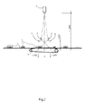
- the system of Figure 1 also comprises a measurement station 4, which in turn comprises cameras 5 and mirrors 6, the positioning of which defines the measurement station's 4 measurement area 7, within which measurement area 7 the pieces of sawn timber 3 can be imaged.
- the system of Figure 1 is viewed from the side, i.e. from the direction of the end of a piece of sawn timber 3 in the measuring area 7.
- the figure shows from the side direction the elements shown in Figure 1 .
- the figure shows the lights 8, for illuminating the sawn timber 3, which belong to the measuring station 4.
- the lights 8 illuminate the piece of sawn timber 3 from two different directions.
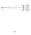
- Figure 3 shows the creation of an image in the measuring station 4 of Figure 1 .
- Figure 3 shows the matrix-camera element 9, the lens 10, and the surface 11 of the object being imaged (the top surface or bottom surface of the piece of sawn timber 3), as well as the image 12 of the object being imaged on a CCD or CMOS matrix of the matrix-camera element 9.
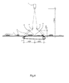
- Figure 4 shows one possible variation of the arrangement of Figure 2 .
- the cameras 5 image the piece of sawn timber 3 from directly between the mirrors 6 and, in addition, as two mirror images through the mirrors 6.
- the arrangements differ from each other in that, in the device of Figure 2 , the mirror images are reflected from between the mirrors 6, and, in the device of Figure 4 , from the opposite sides of the mirrors 6.
- the imaging areas formed by the direct imaging and the mirror images can partly overlap, the measurement area 7 being thus more compact.
- the direct imaging area and the mirror images are located at a distance from each other, so that the measurement area 7 is spread over a wider area.
- the cameras 5 image the piece of sawn timber 3 at essentially right angles.
- a possible variation is one in which the cameras 5 image the timber 3 being examined in the plane of the cross-sections of Figures 2 and 4 at other than essentially right angles, i.e. the cameras' imaging direction is deviated by tilting and moving the cameras towards the arrival or departure directions of the pieces of sawn timber.
- sawn goods are imaged with the intention of automatically grading their quality and optimizing the pieces of sawn timber.
- imaging it is wished to determine, for example, each piece's width, thickness, length, and the width and depth of any waney edges.
- knots, resin pockets, splits, rot, bluing, and other factors affecting the quality and value of a sawn piece can be imaged from the faces and edges.
- the pieces of sawn timber 3 are transported on a main conveyor 1, i.e. a transverse scraper conveyor, which pushes the pieces forwards with the aid of chains and slats attached to them.
- the belts of the measurement conveyor 2 pull the pieces 3 off the slats of the main conveyor 1, so that their edges can be imaged unobstructedly.
- a typical speed is 100 - 200 pieces per minute.
- the traditional way is to image the pieces at two measuring stations and rotate the pieces of sawn timber mechanically between the stations. Using a three-direction measuring station, both sides and the end face of a piece can be imaged.
- the pieces of sawn timber are imaged in three directions in a measuring station 4, using a single matrix camera, in such a way that the measuring areas 7 cover directly the upper surface of the piece and, with the aid of mirrors 6, both of its sides.
- the imaging matrices 9 of the camera can be, for example, CCD or CMOS or corresponding types.
- each piece 3 comprises a top surface and a bottom surface, as well as sides that connect them, the system being arranged to image the top surface and at least one side as the piece 3 travels past the measuring area 7 of the system.
- the system comprises at least one matrix camera 5, which is positioned in a first position relative to the path of the pieces of sawn timber 3, for imaging a piece of sawn timber 3.
- the system comprises at least one mirror 6, which is positioned in a second position relative to the path of the pieces 3 and the said first position.
- the first and second positions are selected in such a way that each piece of sawn timber 3 passing transversely can be imaged using the said at least one matrix camera 5 directly from a first direction and through the said at least one mirror 6 as a mirror image from at least one second direction, which is a different direction to the first direction.
- the said at least one matrix camera 5 comprises two, three, or more matrix cameras 5, which are located in a transverse row.
- the transverse direction refers to the direction transverse to the direction of travel of the pieces of sawn timber, i.e. the longitudinal direction of the row is essentially parallel to the longitudinal direction of the pieces 3 being imaged.
- the said at least one mirror 6 comprises two, three, or more mirrors, which are located in a transverse-direction row.
- the transverse direction refers to a direction corresponding to that described in the previous paragraph.
- the mirrors 6 are placed out of the path of travel of the pieces of sawn timber, as is shown in Fig. 2 .
- the mirrors 6 are located above a level of the main conveyor 1 and also above the measurement conveyor 2 at a first height that is more than a designed greatest thickness of the pieces of sawn timber 3.
- the height is also greater than the height of the slats 1.
- the first height is measured up to the lowest edge or part of the mirrors 6.
- the purpose of this design is to allow the pieces of sawn timber 3 to transversely pass the measuring station 4 without any obstruction by the mirrors 6.
- the mirrors 6 are conventional mirrors including a reflecting metal surface and the path of light from the pieces of sawn timber 3 to the at least one matrix camera 5 comprises substantially one single reflection.
- the system comprises at least one second mirror 6, which is positioned in a third position relative to the path of the pieces of sawn timber 3 and to the said first position.
- the third position is selected in such a way that each piece of sawn wood 3 travelling transversely past can be imaged using at least one matrix camera 5 through the said at least one second mirror 6, as a second mirror image from at least one third direction, which is a different direction to the first direction and the second directions.
- the said at least one second mirror 6 comprises two, three, or more second mirrors 6, which are located in a transverse row in a corresponding manner to the first mirrors, but situated in a different location.
- the first direction is substantially perpendicular to the direction of travel of the pieces of sawn timber and to at least a portion of the top surface of the piece 3, when the piece is in the measuring area of a respective at least one matrix camera 5. Positioning of this kind is shown in Figures 2 and 4 .
- the first direction is tilted towards the direction of approach or departure of the piece of sawn timber 3 from the direction which is substantially perpendicular to the direction of travel of the piece and at least a portion of the top surface of the piece 3, when the piece is in the measuring area 7 of the corresponding at least one matrix camera 5.
- the second direction is tilted at an angle, relative to the first direction, facing the direction of approach or departure of the sawn piece 3.
- the said at least one matrix camera 5 comprises two, three, or more matrix cameras 5, which are situated in a first transverse row, and correspondingly the said at least one mirror 6 also comprises two, three, or more mirrors 6, which are situated in a second transverse row.
- the system comprises second two, three, or more mirrors 6, which are situated in a third transverse row, and the first, second, and third rows are positioned in such a way that the measuring area 7 is situated substantially between the second and third rows, seen from the direction of the first row.
- Figure 2 One such embodiment is shown in Figure 2 .
- the system comprises lights 8, which are arranged to illuminate a sawn piece 3 in the measuring area 7.
- the lights 8 are positioned in a single row of lights, which illuminates the sawn piece 3 from one direction.
- a single row of mirrors Such an embodiment is suitable for use, for example, when the measuring station 4 comprises a single row of mirrors.
- the entire system preferably comprises two measuring stations 4, between which the sawn piece 3 is rotated. I.e., in the system's two measuring stations, the upper face and one side are measured in both stations (the sawn piece being rotated between the measuring stations).
- One row of lights of each measuring station 4 is situated directly between the view of the matrix camera 5 and the view coming through the mirror 6, or close to the direction of the axis of symmetry of these views.
- the lights 8 are positioned in two rows of lights, which are arranged to illuminate a sawn piece 3 in the measuring area 7 from two different directions.
- Figure 2 and Figure 4 show such an embodiment.
- the lights 8 are situated in more than two rows of light, which are arranged to illuminate a sawn piece 3 in the measuring area 7 from more than two different directions.
- the system comprises a second corresponding group of matrix cameras 5 and mirrors 6 positioned on the path of the sawn pieces 3 between the first group and the sawn-piece rotating device, in such a way that, with the aid of the first group, the top surface and at least one side of each sawn piece 3 can be imaged and, with the aid of the second group, the bottom surface and at least the second side of each sawn piece 3 can be imaged.
- the system is adapted to image the pieces of sawn timber 3 during their transverse movement past the measuring area 7 of the system. This means that the operation is continuous. Thus, the main conveyor 1 and/or the measurement conveyor 2 are not stopped for the imaging operation and the pieces of sawn timber are under movement when they are imaged.
- a system for imaging pieces of sawn timber that travel past the system transversely wherein each piece of sawn timber comprises a top surface and a bottom surface as well as sides connecting the top and bottom surfaces.
- the system is adapted to image the top surface and at least one side as the piece of sawn timber travels past a measuring area of the system.
- the system comprises at least one matrix camera for imaging the pieces of sawn timber.
- the at least one matrix camera positioned in a first position relative to a path of the travel of the pieces of sawn timber.
- the system also comprises at least one mirror positioned in a second position relative to the first position and the path of the travel of the pieces of sawn timber. The second position is above the top surfaces of the pieces of sawn timber travelling past the system.
- the first and second positions are arranged to allow imaging of each piece of sawn timber from a first direction and a second direction.
- the first direction is from the top surface of the piece of sawn timber directly to the at least one matrix camera and the second direction is from one of the sides of the piece of sawn timber to the at least one mirror and further as a reflected mirror image to the at least one matrix camera.
- a system for imaging pieces of sawn timber that travel past the system transversely wherein each piece of sawn timber comprises a top surface and a bottom surface as well as sides connecting the top and bottom surfaces.
- the system is adapted to image the top surface and at least one side as the piece of sawn timber travels past a measuring area of the system.
- the system comprises at least one matrix camera for imaging the pieces of sawn timber, which at least one matrix camera is positioned in a first position relative to a path of the travel of the pieces of sawn timber.
- the system further comprises at least one mirror positioned in a second position relative to the first position and the path of the travel of the pieces of sawn timber, the second position being above the top surfaces of the pieces of sawn timber travelling past the system.
- the first and second positions are arranged to allow imaging of each piece of sawn timber from a first direction and a second direction such that the first direction is from the top surface of the piece of sawn timber directly to the at least one matrix camera.
- the second direction is from one of the sides of the piece of sawn timber to the at least one mirror and further as a reflected mirror image to the at least one matrix camera such that the reflected mirror image is formed by a single reflection.
Landscapes
- Engineering & Computer Science (AREA)
- Life Sciences & Earth Sciences (AREA)
- General Physics & Mathematics (AREA)
- Physics & Mathematics (AREA)
- Health & Medical Sciences (AREA)
- Wood Science & Technology (AREA)
- Chemical & Material Sciences (AREA)
- General Health & Medical Sciences (AREA)
- Immunology (AREA)
- Analytical Chemistry (AREA)
- Biochemistry (AREA)
- Pathology (AREA)
- Textile Engineering (AREA)
- Medicinal Chemistry (AREA)
- Food Science & Technology (AREA)
- Biomedical Technology (AREA)
- Multimedia (AREA)
- Signal Processing (AREA)
- Length Measuring Devices By Optical Means (AREA)
Abstract
Description
- The invention relates to a system, according to the preamble to
Claim 1, for imaging sawn timber. -
Publication WO 00/62011 A1 - In the transverse-measurement method, the sawn timber travels past the apparatus transversely, i.e. the apparatus images the pieces of sawn timber essentially simultaneously over their entire length. Correspondingly, the so-called longitudinal method is also known, in which the sawn pieces pass the imaging apparatus in their longitudinal direction, in which case the apparatus images the sawn pieces at one time over their entire width. In the longitudinal method, the transportation of sawn timber through the apparatus takes longer however, as pieces of sawn timber are typically considerably longer than they are wide.
- In the apparatus described in
publication WO 00/62011 A1 - The invention is intended to create a new solution for the imaging of sawn timber.
- The invention is based on the piece of sawn timber passing the measurement area being imaged using a matrix camera simultaneously both directly and with the aid of at least one mirror image formed through at least one mirror, in which case image material is assembled simultaneously from at least two, and in some embodiment even three faces of the piece of sawn timber.
- More specifically, the method according to the invention is characterized by what is stated in the characterizing portion of
Claim 1. - With the aid of the invention, a new solution is created for the imaging of sawn timber.
- The invention also makes possible several different embodiments, which offer additional advantages.
- For example, the invention has embodiments, in which the number of cameras can be reduced compared to known solutions. This is because with the aid of the embodiments the same measurement element can be used to image all three faces of a piece of sawn timber.
- The invention also has embodiments, which facilitate the calibration of the cameras.
- The invention also has embodiments, which permit a more compact measurement area than known solutions, making it also easier to implement the illumination of the measurement area. At the same time, the measurement conveyor can also be implemented in a shorter form.
- In the following, the invention is examined with the aid of examples and with reference to the accompanying drawings.
-
Figure 1 shows a schematic drawing of a top view of the arrangement according to one embodiment. -
Figure 2 shows a schematic drawing of a side view of the arrangement according to one embodiment. -
Figure 3 shows an example of the creation of an image in one embodiment. -
Figure 4 shows a schematic drawing of a side view of the arrangement according to a second embodiment. - The system of
Figure 1 comprises amain conveyor 1, which includes a chain and slats for transporting pieces ofsawn timber 3 transversely to themeasurement conveyor 2 and then away from themeasurement conveyor 2. Themeasurement conveyor 2 is, for its part, typically a belt conveyor. - The system of
Figure 1 also comprises ameasurement station 4, which in turn comprisescameras 5 andmirrors 6, the positioning of which defines the measurement station's 4 measurement area 7, within which measurement area 7 the pieces ofsawn timber 3 can be imaged. - In
Figure 2 , the system ofFigure 1 is viewed from the side, i.e. from the direction of the end of a piece ofsawn timber 3 in the measuring area 7. The figure shows from the side direction the elements shown inFigure 1 . In addition, the figure shows thelights 8, for illuminating thesawn timber 3, which belong to themeasuring station 4. In the embodiment ofFigure 2 , thelights 8 illuminate the piece ofsawn timber 3 from two different directions. -
Figure 3 shows the creation of an image in themeasuring station 4 ofFigure 1 .Figure 3 shows the matrix-camera element 9, thelens 10, and thesurface 11 of the object being imaged (the top surface or bottom surface of the piece of sawn timber 3), as well as theimage 12 of the object being imaged on a CCD or CMOS matrix of the matrix-camera element 9. -
Figure 4 shows one possible variation of the arrangement ofFigure 2 . Common to both arrangements is that thecameras 5 image the piece ofsawn timber 3 from directly between themirrors 6 and, in addition, as two mirror images through themirrors 6. The arrangements differ from each other in that, in the device ofFigure 2 , the mirror images are reflected from between themirrors 6, and, in the device ofFigure 4 , from the opposite sides of themirrors 6. In the device ofFigure 2 , the imaging areas formed by the direct imaging and the mirror images can partly overlap, the measurement area 7 being thus more compact. In the device ofFigure 4 on the other hand, the direct imaging area and the mirror images are located at a distance from each other, so that the measurement area 7 is spread over a wider area. - Seen on the plane of the cross-sections of
Figures 2 and4 , thecameras 5 image the piece ofsawn timber 3 at essentially right angles. A possible variation is one in which thecameras 5 image thetimber 3 being examined in the plane of the cross-sections ofFigures 2 and4 at other than essentially right angles, i.e. the cameras' imaging direction is deviated by tilting and moving the cameras towards the arrival or departure directions of the pieces of sawn timber. - One further possible variation to all of the embodiments described above is one in which only one
mirror 6 or line of mirrors is used instead of twomirrors 6 or lines of mirrors. - Generally, sawn goods are imaged with the intention of automatically grading their quality and optimizing the pieces of sawn timber. By means of imaging, it is wished to determine, for example, each piece's width, thickness, length, and the width and depth of any waney edges. In addition, knots, resin pockets, splits, rot, bluing, and other factors affecting the quality and value of a sawn piece can be imaged from the faces and edges.
- In the embodiments of the figures, the pieces of
sawn timber 3 are transported on amain conveyor 1, i.e. a transverse scraper conveyor, which pushes the pieces forwards with the aid of chains and slats attached to them. The belts of themeasurement conveyor 2 pull thepieces 3 off the slats of themain conveyor 1, so that their edges can be imaged unobstructedly. Nowadays, a typical speed is 100 - 200 pieces per minute. The traditional way is to image the pieces at two measuring stations and rotate the pieces of sawn timber mechanically between the stations. Using a three-direction measuring station, both sides and the end face of a piece can be imaged. - In the arrangement according to the embodiments, the pieces of sawn timber are imaged in three directions in a
measuring station 4, using a single matrix camera, in such a way that the measuring areas 7 cover directly the upper surface of the piece and, with the aid ofmirrors 6, both of its sides. Theimaging matrices 9 of the camera can be, for example, CCD or CMOS or corresponding types. - With the aid of the embodiments described above a system can be implemented for the imaging of pieces of
sawn timber 3 travelling transversely past the system, in which eachpiece 3 comprises a top surface and a bottom surface, as well as sides that connect them, the system being arranged to image the top surface and at least one side as thepiece 3 travels past the measuring area 7 of the system. - In one embodiment, the system comprises at least one
matrix camera 5, which is positioned in a first position relative to the path of the pieces ofsawn timber 3, for imaging a piece ofsawn timber 3. In addition, the system comprises at least onemirror 6, which is positioned in a second position relative to the path of thepieces 3 and the said first position. According to the embodiment, the first and second positions are selected in such a way that each piece ofsawn timber 3 passing transversely can be imaged using the said at least onematrix camera 5 directly from a first direction and through the said at least onemirror 6 as a mirror image from at least one second direction, which is a different direction to the first direction. - According to one embodiment, the said at least one
matrix camera 5 comprises two, three, ormore matrix cameras 5, which are located in a transverse row. In this case, the transverse direction refers to the direction transverse to the direction of travel of the pieces of sawn timber, i.e. the longitudinal direction of the row is essentially parallel to the longitudinal direction of thepieces 3 being imaged. - According to one embodiment, the said at least one
mirror 6 comprises two, three, or more mirrors, which are located in a transverse-direction row. In this case, the transverse direction refers to a direction corresponding to that described in the previous paragraph. - According to an embodiment, the
mirrors 6 are placed out of the path of travel of the pieces of sawn timber, as is shown inFig. 2 . For example, themirrors 6 are located above a level of themain conveyor 1 and also above themeasurement conveyor 2 at a first height that is more than a designed greatest thickness of the pieces ofsawn timber 3. At the same time, the height is also greater than the height of theslats 1. The first height is measured up to the lowest edge or part of themirrors 6. The purpose of this design is to allow the pieces ofsawn timber 3 to transversely pass the measuringstation 4 without any obstruction by themirrors 6. - According to an embodiment, the
mirrors 6 are conventional mirrors including a reflecting metal surface and the path of light from the pieces ofsawn timber 3 to the at least onematrix camera 5 comprises substantially one single reflection. - According to one embodiment, the system comprises at least one
second mirror 6, which is positioned in a third position relative to the path of the pieces ofsawn timber 3 and to the said first position. The third position is selected in such a way that each piece ofsawn wood 3 travelling transversely past can be imaged using at least onematrix camera 5 through the said at least onesecond mirror 6, as a second mirror image from at least one third direction, which is a different direction to the first direction and the second directions. - According to one embodiment, the said at least one
second mirror 6 comprises two, three, or moresecond mirrors 6, which are located in a transverse row in a corresponding manner to the first mirrors, but situated in a different location. - According to one embodiment, the first direction is substantially perpendicular to the direction of travel of the pieces of sawn timber and to at least a portion of the top surface of the
piece 3, when the piece is in the measuring area of a respective at least onematrix camera 5. Positioning of this kind is shown inFigures 2 and4 . - According to a second embodiment, the first direction is tilted towards the direction of approach or departure of the piece of
sawn timber 3 from the direction which is substantially perpendicular to the direction of travel of the piece and at least a portion of the top surface of thepiece 3, when the piece is in the measuring area 7 of the corresponding at least onematrix camera 5. - According to one embodiment, the second direction is tilted at an angle, relative to the first direction, facing the direction of approach or departure of the sawn
piece 3. - According to one embodiment, the said at least one
matrix camera 5 comprises two, three, ormore matrix cameras 5, which are situated in a first transverse row, and correspondingly the said at least onemirror 6 also comprises two, three, ormore mirrors 6, which are situated in a second transverse row. In addition, the system comprises second two, three, ormore mirrors 6, which are situated in a third transverse row, and the first, second, and third rows are positioned in such a way that the measuring area 7 is situated substantially between the second and third rows, seen from the direction of the first row. One such embodiment is shown inFigure 2 . - According to one embodiment, the system comprises
lights 8, which are arranged to illuminate asawn piece 3 in the measuring area 7. - According to one embodiment, the
lights 8 are positioned in a single row of lights, which illuminates the sawnpiece 3 from one direction. Such an embodiment is suitable for use, for example, when the measuringstation 4 comprises a single row of mirrors. Of course, in that case the entire system preferably comprises two measuringstations 4, between which thesawn piece 3 is rotated. I.e., in the system's two measuring stations, the upper face and one side are measured in both stations (the sawn piece being rotated between the measuring stations). One row of lights of each measuringstation 4 is situated directly between the view of thematrix camera 5 and the view coming through themirror 6, or close to the direction of the axis of symmetry of these views. - According to a second embodiment, the
lights 8 are positioned in two rows of lights, which are arranged to illuminate asawn piece 3 in the measuring area 7 from two different directions.Figure 2 andFigure 4 show such an embodiment. - According to a third embodiment, the
lights 8 are situated in more than two rows of light, which are arranged to illuminate asawn piece 3 in the measuring area 7 from more than two different directions. - According to one embodiment, the system comprises a second corresponding group of
matrix cameras 5 and mirrors 6 positioned on the path of thesawn pieces 3 between the first group and the sawn-piece rotating device, in such a way that, with the aid of the first group, the top surface and at least one side of eachsawn piece 3 can be imaged and, with the aid of the second group, the bottom surface and at least the second side of eachsawn piece 3 can be imaged. - According to an embodiment, the system is adapted to image the pieces of
sawn timber 3 during their transverse movement past the measuring area 7 of the system. This means that the operation is continuous. Thus, themain conveyor 1 and/or themeasurement conveyor 2 are not stopped for the imaging operation and the pieces of sawn timber are under movement when they are imaged. - According to an embodiment, there is provided a system for imaging pieces of sawn timber that travel past the system transversely, wherein each piece of sawn timber comprises a top surface and a bottom surface as well as sides connecting the top and bottom surfaces. The system is adapted to image the top surface and at least one side as the piece of sawn timber travels past a measuring area of the system. The system comprises at least one matrix camera for imaging the pieces of sawn timber. The at least one matrix camera positioned in a first position relative to a path of the travel of the pieces of sawn timber. The system also comprises at least one mirror positioned in a second position relative to the first position and the path of the travel of the pieces of sawn timber. The second position is above the top surfaces of the pieces of sawn timber travelling past the system. According to this embodiment, the first and second positions are arranged to allow imaging of each piece of sawn timber from a first direction and a second direction. The first direction is from the top surface of the piece of sawn timber directly to the at least one matrix camera and the second direction is from one of the sides of the piece of sawn timber to the at least one mirror and further as a reflected mirror image to the at least one matrix camera.
- According to another embodiment, there is provided a system for imaging pieces of sawn timber that travel past the system transversely, wherein each piece of sawn timber comprises a top surface and a bottom surface as well as sides connecting the top and bottom surfaces. The system is adapted to image the top surface and at least one side as the piece of sawn timber travels past a measuring area of the system. According to this embodiment, the system comprises at least one matrix camera for imaging the pieces of sawn timber, which at least one matrix camera is positioned in a first position relative to a path of the travel of the pieces of sawn timber. The system further comprises at least one mirror positioned in a second position relative to the first position and the path of the travel of the pieces of sawn timber, the second position being above the top surfaces of the pieces of sawn timber travelling past the system. In the embodiment, the first and second positions are arranged to allow imaging of each piece of sawn timber from a first direction and a second direction such that the first direction is from the top surface of the piece of sawn timber directly to the at least one matrix camera. On the other hand, the second direction is from one of the sides of the piece of sawn timber to the at least one mirror and further as a reflected mirror image to the at least one matrix camera such that the reflected mirror image is formed by a single reflection.
- On the basis of the examples described above, it is obvious that, within the scope of the invention, it is possible to implement numerous solutions differing from the embodiments described above. Thus, it is not intended to restrict the invention to relate to only the aforementioned examples; instead the patent protection should be examined to the full extent of the accompanying Claims.
Claims (15)
- A system for imaging pieces of sawn timber (3) that travel past the system transversely, wherein each piece of sawn timber (3) comprises a top surface and a bottom surface as well as sides connecting them, and which system is arranged to image the top surface and at least one side as the piece of sawn timber (3) travels past a measuring area (7) of the system, characterized in that the system comprises:- at least one matrix camera (5) for imaging the piece of sawn timber (3), the at least one matrix camera (5) positioned in a first position relative to a path of the travel of the pieces of sawn timber (3), and- at least one mirror (6) positioned in a second position relative to the path of the pieces of sawn timber (3) and to the said first position,said first and second positions selected such that each piece of sawn timber (3) passing transversely can be imaged using the said at least one matrix camera (5) directly from a first direction and through the said at least one mirror (6) as a mirror image from at least one second direction.
- The system according to Claim 1, characterized in that the said at least one matrix camera (5) comprises two, three, or more matrix cameras (5), which are situated in a transverse row.
- The system according to Claim 1 or 2, characterized in that the said at least one mirror (6) comprises two, three, or more mirrors (6), which are situated in a transverse row.
- The system according to any one of Claims 1 - 3, characterized in that the system comprises at least one second mirror (6), which is positioned in a third position relative to the path of the pieces of sawn timber (3) and to the said first position, which third position is selected such that each piece of sawn timber (3) passing transversely can be imaged using the said at least one matrix camera(5) as a second mirror image through the said at least one second mirror (6) from at least one third direction.
- The system according to Claim 4, characterized in that the said at least one second mirror (6) comprises two, three, or more second mirrors (6), which are situated in a transverse row.
- The system according to any one of Claims 1 - 5, characterized in that the first direction is substantially at right angles to the direction of travel of a piece of sawn timber and to at least a portion of the top surface of the piece of sawn timber (3) when the piece of sawn timber is in the measuring area of the corresponding at least one matrix camera (5).
- The system according to any one of Claims 1 - 5, characterized in that the first direction is tilted towards the direction of arrival or departure of the piece of sawn timber (3) from a direction that is substantially perpendicular relative to the direction of travel of the piece of sawn timber and at least a portion of the top surface of the piece of sawn timber (3), when the piece of sawn timber is in the measuring area (7) of the corresponding at least one matrix camera (5).
- The system according to any one of Claims 1 - 7, characterized in that the second direction is at a tilted angle directed towards the direction of arrival or departure of the piece of sawn timber (3), relative to the first direction.
- The system according to any one of Claims 1 - 8, characterized in that
the said at least one matrix camera (5) comprises two, three, or more matrix cameras (5), which are situated in a first transverse row,
the said at least one mirror (6) comprises two, three, or more mirrors (6), which are situated in a second transverse row,
the said at least one mirror (6) comprises second two, three, or more mirrors (6), which are situated in a third transverse row, and
the first, second, and third rows are positioned such way that the measuring area (7) is situated substantially between the second and third rows, when seen from the direction of the first row. - The system according to any one of Claims 1 - 9, characterized in that it comprises lights (8), which are arranged to illuminate a piece of sawn timber (3) in the measuring area.
- The system according to Claim 10, characterized in that the lights (8) are positioned in at least two transverse rows of light, in such a way that they illuminate a piece of sawn timber (3) in the measuring area from at least two different directions.
- The system according to any one of Claims 1 - 10, characterized in that it comprises a second corresponding group of matrix cameras (5) and mirrors (6) positioned in the path of the pieces of sawn timber (3) after the first group and the sawn-piece rotation device, in such a way that, with the aid of the first group the top surface and at least one side of each piece of sawn timber (3) can be imaged and, with the aid of the second group the bottom surface and at least the second side of the piece of sawn timber (3) can be imaged.
- The system according to any one of Claims 1 - 12, characterized in that the mirrors (6) are located at a first height above a level of the main conveyor (1) and a level of a measurement conveyor (2) for letting the pieces of sawn timber (3) supported by the main conveyor (1) and/or the measurement conveyor (2) pass transversely under the mirrors (6).
- The system according to any one of Claims 1 - 13, characterized in that a path of light from the imaged pieces of sawn timber (3) to the at least one matrix camera (5) comprises one single reflection.
- The system according to any one of Claims 1 - 14, characterized in that the system is adapted to image the pieces of sawn timber (3) during their transverse movement past the measuring area (7) of the system.
Applications Claiming Priority (1)
| Application Number | Priority Date | Filing Date | Title |
|---|---|---|---|
| FI20125733A FI125973B (en) | 2012-06-27 | 2012-06-27 | System for photographing wood products |
Publications (2)
| Publication Number | Publication Date |
|---|---|
| EP2679951A2 true EP2679951A2 (en) | 2014-01-01 |
| EP2679951A3 EP2679951A3 (en) | 2017-07-05 |
Family
ID=48703388
Family Applications (1)
| Application Number | Title | Priority Date | Filing Date |
|---|---|---|---|
| EP13397522.7A Withdrawn EP2679951A3 (en) | 2012-06-27 | 2013-06-19 | System for imaging sawn timber |
Country Status (4)
| Country | Link |
|---|---|
| US (1) | US20140002634A1 (en) |
| EP (1) | EP2679951A3 (en) |
| CA (1) | CA2820471A1 (en) |
| FI (1) | FI125973B (en) |
Cited By (3)
| Publication number | Priority date | Publication date | Assignee | Title |
|---|---|---|---|---|
| EP3462164A1 (en) * | 2017-09-29 | 2019-04-03 | Baumer Inspection GmbH | Assembly and method of inspecting moved plate-shaped objects |
| EP3916378A1 (en) * | 2020-05-29 | 2021-12-01 | MICROTEC S.r.l. | Method and apparatus for capturing an image of a lateral face of a wooden board |
| EP4227673A1 (en) * | 2022-01-27 | 2023-08-16 | Finnos Oy | Apparatus for capturing images of elongated timber |
Families Citing this family (7)
| Publication number | Priority date | Publication date | Assignee | Title |
|---|---|---|---|---|
| CN104613894A (en) * | 2015-01-26 | 2015-05-13 | 中山市美捷时包装制品有限公司 | A visual high-speed detection system |
| CN107246841A (en) * | 2017-05-27 | 2017-10-13 | 武汉理工大学 | A kind of multiple views grouping system device of auto parts and components |
| CN109323664B (en) * | 2017-07-31 | 2021-06-29 | 深圳市炫硕智造技术有限公司 | Double-side image testing mechanism |
| CN111389765A (en) * | 2020-03-31 | 2020-07-10 | 上海电气集团股份有限公司 | Product surface quality detection method and device and product sorting system |
| CN111521618B (en) * | 2020-04-27 | 2023-01-31 | 衢州职业技术学院 | Rapid bearing defect detection device for industrial robot and detection method thereof |
| US12028497B1 (en) | 2023-05-22 | 2024-07-02 | Certified Guaranty Company, LLC | Simultaneous single obverse and reverse imaging of collectible items |
| CN120733997B (en) * | 2025-08-29 | 2025-11-21 | 闽江师范高等专科学校 | Sawn timber surface defect image processing method and sawn timber sorting system |
Citations (1)
| Publication number | Priority date | Publication date | Assignee | Title |
|---|---|---|---|---|
| WO2000062011A1 (en) | 1999-03-30 | 2000-10-19 | Fin Scan Oy | Method and apparatus for determination of dimensions and external properties of three-demensional objects such as timber in a transverse measurement system |
Family Cites Families (6)
| Publication number | Priority date | Publication date | Assignee | Title |
|---|---|---|---|---|
| US4891530A (en) * | 1986-02-22 | 1990-01-02 | Helmut K. Pinsch Gmbh & Co. | Testing or inspecting apparatus and method for detecting differently shaped surfaces of objects |
| DE19716468C2 (en) * | 1997-04-21 | 1999-07-08 | Autronic Bildverarbeitung | Device for surface inspection, especially of wood |
| US6701081B1 (en) * | 2000-06-06 | 2004-03-02 | Air Controls, Inc. | Dual camera mount for stereo imaging |
| CA2378625A1 (en) * | 2002-03-20 | 2003-09-20 | Martin Castonguay | High-performance grade optimizer |
| US7406190B2 (en) * | 2003-07-24 | 2008-07-29 | Lucidyne Technologies, Inc. | Wood tracking by identification of surface characteristics |
| DE102007030865A1 (en) * | 2007-06-25 | 2009-07-09 | GreCon Dimter Holzoptimierung Süd GmbH & Co. KG | Apparatus and method for scanning solid woods |
-
2012
- 2012-06-27 FI FI20125733A patent/FI125973B/en active IP Right Grant
-
2013
- 2013-06-19 EP EP13397522.7A patent/EP2679951A3/en not_active Withdrawn
- 2013-06-21 CA CA2820471A patent/CA2820471A1/en not_active Abandoned
- 2013-06-26 US US13/927,277 patent/US20140002634A1/en not_active Abandoned
Patent Citations (1)
| Publication number | Priority date | Publication date | Assignee | Title |
|---|---|---|---|---|
| WO2000062011A1 (en) | 1999-03-30 | 2000-10-19 | Fin Scan Oy | Method and apparatus for determination of dimensions and external properties of three-demensional objects such as timber in a transverse measurement system |
Cited By (4)
| Publication number | Priority date | Publication date | Assignee | Title |
|---|---|---|---|---|
| EP3462164A1 (en) * | 2017-09-29 | 2019-04-03 | Baumer Inspection GmbH | Assembly and method of inspecting moved plate-shaped objects |
| EP3916378A1 (en) * | 2020-05-29 | 2021-12-01 | MICROTEC S.r.l. | Method and apparatus for capturing an image of a lateral face of a wooden board |
| US12061153B2 (en) | 2020-05-29 | 2024-08-13 | Microtec S.R.L. | Method and apparatus for capturing an image of a lateral face of a wooden board |
| EP4227673A1 (en) * | 2022-01-27 | 2023-08-16 | Finnos Oy | Apparatus for capturing images of elongated timber |
Also Published As
| Publication number | Publication date |
|---|---|
| CA2820471A1 (en) | 2013-12-27 |
| EP2679951A3 (en) | 2017-07-05 |
| US20140002634A1 (en) | 2014-01-02 |
| FI125973B (en) | 2016-05-13 |
| FI20125733L (en) | 2013-12-28 |
Similar Documents
| Publication | Publication Date | Title |
|---|---|---|
| EP2679951A2 (en) | System for imaging sawn timber | |
| EP3066456B1 (en) | Inspection apparatus | |
| US8520220B2 (en) | Apparatus for measuring the dimensions of an object | |
| EP2781912B1 (en) | Inspection system | |
| KR102246301B1 (en) | Appearance inspection apparatus | |
| KR20170107952A (en) | Optical appearance inspection device and optical appearance inspection system using same | |
| KR101697216B1 (en) | Plate glass inspection unit and manufacturing facility | |
| JP6639181B2 (en) | Imaging device, production system, imaging method, program, and recording medium | |
| US12061153B2 (en) | Method and apparatus for capturing an image of a lateral face of a wooden board | |
| US10099258B2 (en) | Article conveying system with diffuse illumination | |
| RU2717020C1 (en) | Method and device for detecting position of abdomen/back of fish transported by means of transporting device | |
| CA2738368C (en) | Multiple vision system and method | |
| JPH102868A (en) | Method and apparatus for optically detecting defects in a translucent sheet | |
| WO2013080093A1 (en) | Inspection system | |
| FI124426B (en) | Method and apparatus for determining the dimensions and external properties of three-dimensional pieces, e.g. wood | |
| US10247678B1 (en) | Arrangement and procedure for the inspection of moving plate-shaped objects | |
| JP2002080121A (en) | Sealant feeding device | |
| JP2009115489A (en) | Appearance inspection device | |
| EP4227673A1 (en) | Apparatus for capturing images of elongated timber | |
| JP2010014735A (en) | Visual inspection apparatus | |
| EP1790975B1 (en) | A device for welding check of welded trays | |
| FI61099C (en) | ANORDINATION AND FARING FACILITY MAINTENANCE AV SAOGVIRKE SPECIELLT UPPTAECKANDE AV VANKANT | |
| US20250244255A1 (en) | Scanning of objects | |
| JP6931570B2 (en) | Inspection equipment | |
| FI95415B (en) | Optical method for determining the three-dimensional shape of an object |
Legal Events
| Date | Code | Title | Description |
|---|---|---|---|
| PUAI | Public reference made under article 153(3) epc to a published international application that has entered the european phase |
Free format text: ORIGINAL CODE: 0009012 |
|
| AK | Designated contracting states |
Kind code of ref document: A2 Designated state(s): AL AT BE BG CH CY CZ DE DK EE ES FI FR GB GR HR HU IE IS IT LI LT LU LV MC MK MT NL NO PL PT RO RS SE SI SK SM TR |
|
| AX | Request for extension of the european patent |
Extension state: BA ME |
|
| PUAL | Search report despatched |
Free format text: ORIGINAL CODE: 0009013 |
|
| AK | Designated contracting states |
Kind code of ref document: A3 Designated state(s): AL AT BE BG CH CY CZ DE DK EE ES FI FR GB GR HR HU IE IS IT LI LT LU LV MC MK MT NL NO PL PT RO RS SE SI SK SM TR |
|
| AX | Request for extension of the european patent |
Extension state: BA ME |
|
| RIC1 | Information provided on ipc code assigned before grant |
Ipc: G01N 33/46 20060101ALI20170526BHEP Ipc: G01N 21/898 20060101ALI20170526BHEP Ipc: G01B 11/245 20060101AFI20170526BHEP Ipc: G01B 11/04 20060101ALI20170526BHEP |
|
| STAA | Information on the status of an ep patent application or granted ep patent |
Free format text: STATUS: THE APPLICATION IS DEEMED TO BE WITHDRAWN |
|
| 18D | Application deemed to be withdrawn |
Effective date: 20180106 |