EP2679934A1 - Air conditioning/hot water supply system and control method for air conditioning/hot water supply system - Google Patents
Air conditioning/hot water supply system and control method for air conditioning/hot water supply system Download PDFInfo
- Publication number
- EP2679934A1 EP2679934A1 EP11859342.5A EP11859342A EP2679934A1 EP 2679934 A1 EP2679934 A1 EP 2679934A1 EP 11859342 A EP11859342 A EP 11859342A EP 2679934 A1 EP2679934 A1 EP 2679934A1
- Authority
- EP
- European Patent Office
- Prior art keywords
- hot
- air conditioning
- water supply
- refrigerant
- heat exchanger
- Prior art date
- Legal status (The legal status is an assumption and is not a legal conclusion. Google has not performed a legal analysis and makes no representation as to the accuracy of the status listed.)
- Granted
Links
Images


Classifications
-
- F—MECHANICAL ENGINEERING; LIGHTING; HEATING; WEAPONS; BLASTING
- F25—REFRIGERATION OR COOLING; COMBINED HEATING AND REFRIGERATION SYSTEMS; HEAT PUMP SYSTEMS; MANUFACTURE OR STORAGE OF ICE; LIQUEFACTION SOLIDIFICATION OF GASES
- F25B—REFRIGERATION MACHINES, PLANTS OR SYSTEMS; COMBINED HEATING AND REFRIGERATION SYSTEMS; HEAT PUMP SYSTEMS
- F25B7/00—Compression machines, plants or systems, with cascade operation, i.e. with two or more circuits, the heat from the condenser of one circuit being absorbed by the evaporator of the next circuit
-
- F—MECHANICAL ENGINEERING; LIGHTING; HEATING; WEAPONS; BLASTING
- F24—HEATING; RANGES; VENTILATING
- F24F—AIR-CONDITIONING; AIR-HUMIDIFICATION; VENTILATION; USE OF AIR CURRENTS FOR SCREENING
- F24F5/00—Air-conditioning systems or apparatus not covered by F24F1/00 or F24F3/00, e.g. using solar heat or combined with household units such as an oven or water heater
- F24F5/0096—Air-conditioning systems or apparatus not covered by F24F1/00 or F24F3/00, e.g. using solar heat or combined with household units such as an oven or water heater combined with domestic apparatus
-
- F—MECHANICAL ENGINEERING; LIGHTING; HEATING; WEAPONS; BLASTING
- F25—REFRIGERATION OR COOLING; COMBINED HEATING AND REFRIGERATION SYSTEMS; HEAT PUMP SYSTEMS; MANUFACTURE OR STORAGE OF ICE; LIQUEFACTION SOLIDIFICATION OF GASES
- F25B—REFRIGERATION MACHINES, PLANTS OR SYSTEMS; COMBINED HEATING AND REFRIGERATION SYSTEMS; HEAT PUMP SYSTEMS
- F25B29/00—Combined heating and refrigeration systems, e.g. operating alternately or simultaneously
- F25B29/003—Combined heating and refrigeration systems, e.g. operating alternately or simultaneously of the compression type system
-
- F—MECHANICAL ENGINEERING; LIGHTING; HEATING; WEAPONS; BLASTING
- F25—REFRIGERATION OR COOLING; COMBINED HEATING AND REFRIGERATION SYSTEMS; HEAT PUMP SYSTEMS; MANUFACTURE OR STORAGE OF ICE; LIQUEFACTION SOLIDIFICATION OF GASES
- F25B—REFRIGERATION MACHINES, PLANTS OR SYSTEMS; COMBINED HEATING AND REFRIGERATION SYSTEMS; HEAT PUMP SYSTEMS
- F25B13/00—Compression machines, plants or systems, with reversible cycle
-
- F—MECHANICAL ENGINEERING; LIGHTING; HEATING; WEAPONS; BLASTING
- F25—REFRIGERATION OR COOLING; COMBINED HEATING AND REFRIGERATION SYSTEMS; HEAT PUMP SYSTEMS; MANUFACTURE OR STORAGE OF ICE; LIQUEFACTION SOLIDIFICATION OF GASES
- F25B—REFRIGERATION MACHINES, PLANTS OR SYSTEMS; COMBINED HEATING AND REFRIGERATION SYSTEMS; HEAT PUMP SYSTEMS
- F25B2339/00—Details of evaporators; Details of condensers
- F25B2339/04—Details of condensers
- F25B2339/047—Water-cooled condensers
-
- F—MECHANICAL ENGINEERING; LIGHTING; HEATING; WEAPONS; BLASTING
- F25—REFRIGERATION OR COOLING; COMBINED HEATING AND REFRIGERATION SYSTEMS; HEAT PUMP SYSTEMS; MANUFACTURE OR STORAGE OF ICE; LIQUEFACTION SOLIDIFICATION OF GASES
- F25B—REFRIGERATION MACHINES, PLANTS OR SYSTEMS; COMBINED HEATING AND REFRIGERATION SYSTEMS; HEAT PUMP SYSTEMS
- F25B25/00—Machines, plants or systems, using a combination of modes of operation covered by two or more of the groups F25B1/00 - F25B23/00
- F25B25/005—Machines, plants or systems, using a combination of modes of operation covered by two or more of the groups F25B1/00 - F25B23/00 using primary and secondary systems
Definitions
- the present invention relates to an air conditioning and hot-water supply system having multi-heat-sources which is configured with a two-element refrigerating cycle of an air conditioning cycle and a hot-water supply cycle by heat-exchangeably connecting an air conditioning refrigerant circuit and a hot-water supply refrigerant circuit to each other via an intermediate heat exchanger and a control method of an air conditioning and hot-water supply system.
- Patent Literature 1 discloses a heat pump system which includes a high temperature cycle (hot-water supply cycle) that carries out high temperature outputting, and a medium temperature cycle (air conditioning cycle) that carries out medium temperature outputting or low temperature outputting, and in which an evaporator of the high temperature cycle and a condenser of the medium temperature cycle are configured to be able to exchange heat. According to a technology disclosed in Patent Literature 1, an operation (exhaust heat recovery operation) can be carried out such that exhaust heat of the medium temperature cycle is effectively utilized in the high temperature cycle, and an economic operation can be carried out.
- a high temperature cycle hot-water supply cycle
- a medium temperature cycle air conditioning cycle
- Patent Literature 2 discloses an air-conditioner which can carry out a heating and cooling operation, a hot-water supply operation, a cool storage operation, a heating and cooling and hot-water supply operation or the like. According to a technology disclosed in Patent Literature 2, the respective operations described above can be switched by including plural switching valves and expansion valves. According to the technology disclosed in Patent Literature 2, the respective operations can efficiently be switched.
- exhaust heat of the medium temperature cycle can be utilized as a heat source of the high temperature cycle only when an exhaust heat amount of the medium temperature cycle is larger than a heat absorbing amount of the high temperature cycle.
- the exhaust heat of the medium temperature cycle can be utilized for the heat source of the high temperature cycle, and the exhaust heat recovery operation can be carried out only in a case where a load of the medium temperature cycle (air conditioning load) is high.
- the air-conditioning load is low in an air-conditioning operation for air-conditioning a space having a small internal heat generation such as a space having high insulating performance or a space of few dwellers or the like, or an air-conditioning operation in a state of a low outdoor temperature at nighttime.
- the load of the high temperature cycle may exceed the air conditioning load.
- the technology disclosed in Patent Literature 1 poses a problem that a high temperature cycle cannot be operated as requested only by the exhaust heat of the medium temperature cycle in such a case.
- the air-conditioner disclosed in Patent Literature 2 is configured such that a cascade condenser (intermediate heat exchanger) of recovering exhaust heat of a main cycle (air conditioning cycle) and an outdoor heat exchanger (air conditioning heat source side heat exchanger) of the main cycle are arranged in parallel, and the exhaust heat recovery operation can be carried out by delivering heat to a sub cycle (hot-water supply cycle) by recovering exhaust heat of the main cycle by the cascade condenser by simultaneously operating the cascade condenser and the outdoor heat exchanger.
- a cascade condenser intermediate heat exchanger
- an outdoor heat exchanger air conditioning heat source side heat exchanger
- Patent Literature 2 does not disclose a technology of preferably distributing the refrigerant to the cascade condenser and the outdoor heat exchanger in the main cycle.
- an air conditioning and hot-water supply system which can preferably distribute a refrigerant in a cycle having a large heat amount to a heat exchanger for recovering exhaust heat and a heat exchanger for exhaust heat in the exhaust heat recovery operation and a control method of the air conditioning and hot-water supply system.
- the present invention is an air conditioning and hot-water supply system including an air conditioning refrigerant circuit configuring an air conditioning cycle by circulating an air conditioning refrigerant, a hot-water supply refrigerant circuit configuring a hot-water cycle by circulating a hot-water supply refrigerant, and a control device, further including an intermediate heat exchanger connected in parallel with an air conditioning heat source side heat exchanger for exchanging heat between the air conditioning refrigerant and the atmosphere in the air conditioning refrigerant circuit, and connected in parallel with a hot-water supply heat source side heat exchanger for exchanging heat between the hot-water supply refrigerant and the atmosphere in the hot-water supply refrigerant circuit for exchanging heat between the air conditioning refrigerant and the hot-water supply refrigerant.
- the air conditioning and hot-water supply system further includes air conditioning refrigerant flow-in amount adjusting means for adjusting an amount of the air conditioning refrigerant flowing into the air conditioning heat source side heat exchanger or the intermediate heat exchanger in a cooling operation by the air conditioning cycle, and means for measuring a temperature of an air conditioning heat exchanger outlet for measuring a temperature of an air conditioning heat exchanger outlet of one of the air conditioning heat source side heat exchanger and the intermediate heat exchanger at which the amount of the air conditioning refrigerant flowing into the air conditioning heat source side heat exchanger or the intermediate heat exchanger is adjusted in the cooling operation, in which the control device calculates an air conditioning heat radiating amount in the air conditioning refrigerant circuit, a hot-water supply heat absorbing amount in the hot-water supply refrigerant circuit, a target condensation temperature at the air conditioning refrigerant circuit, and a target evaporation temperature at the hot-water supply refrigerant circuit in a case where the cooling operation by the air conditioning cycle and a hot-water supply operation by the hot-water
- an air conditioning and hot-water supply system which can preferably distribute a refrigerant in a cycle having a large heat amount to a heat exchanger for recovering exhaust heat and a heat exchanger for exhaust heat in an exhaust heat recovery operation and a control method of the air conditioning and hot-water supply.
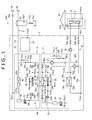
- an air conditioning and hot-water supply system 100 includes an air conditioning refrigerant circuit 5 which carries out an operation by switching a cooling operation and a heating operation by driving an air conditioning refrigerant compressor 21, a hot-water supply refrigerant circuit 6 which carries out a hot-water supply operation by driving a hot-water supply compressor 41, an air conditioning cold/hot-water circulating circuit 8 which carries out air conditioning of an indoor portion of a residence 60, a hot-water supply flow path 9 which carries out hot-water supply by exchanging heat with the hot-water supply refrigerant circuit 6, and a control device 1a which controls the respective operations.
- an air conditioning refrigerant circuit 5 which carries out an operation by switching a cooling operation and a heating operation by driving an air conditioning refrigerant compressor 21, a hot-water supply refrigerant circuit 6 which carries out a hot-water supply operation by driving a hot-water supply compressor 41, an air conditioning cold/hot-water circulating circuit 8 which carries out air conditioning of an indoor portion of a
- the cooling operation and the heating operation indicate a cooling operation and a heating operation of the air conditioning cycle configured by including the air conditioning refrigerant circuit 5.
- the hot-water supply operation indicates a hot-water supply operation of the hot-water supply cycle configured by including the hot-water supply refrigerant circuit 6.
- the air conditioning and hot-water supply system 100 is configured by including a heat pump unit 1 arranged at an outdoor portion of the residence 60 and an indoor unit 2 arranged at an indoor portion thereof.
- the heat pump unit 1 is integrated with the air conditioning refrigerant circuit 5, the hot-water supply refrigerant circuit 6, the air conditioning cold/hot water circulating circuit 8, the hot-water supply flow path 9, and the control device 1a.
- the indoor unit 2 includes an indoor heat exchanger 61 which carries out heat exchange between indoor air of the residence 60 and cold/hot water which flows in the air conditioning cold/hot water circulating circuit 8.
- the air conditioning refrigerant circuit 5 is a circuit which is configured with a refrigerating cycle (air conditioning cycle) by circulating a refrigerant for air conditioning (hereinafter, air conditioning refrigerant).
- the circuit is configured to connect an air conditioning heat source side heat exchanger 24 which exhausts heat by exchanging heat between the atmosphere blown by an air conditioning outdoor fan 25 and the air conditioning refrigerant to an air conditioning refrigerant main circuit 5a which is connected with the air conditioning compressor 21 which compresses the air conditioning refrigerant, a four-way valve (air conditioning flow path switching valve) 22 which switches a flow path of the air conditioning refrigerant, the intermediate heat exchanger 23 which exchanges heat between a refrigerant that circulates in the hot-water supply refrigerant circuit 6 (hereinafter, hot-water supply refrigerant) and the air conditioning refrigerant, an air conditioning refrigerant tank 26, an air conditioning expansion valve 27 which reduces a pressure of the air conditioning refrigerant, and an air conditioning utilizing side
- Fig. 1 it is configured that heat is exchanged between the air conditioning refrigerant that circulates in the air conditioning refrigerant circuit 5 and the air conditioning cold/hot water that circulates in the air conditioning cold/hot water circulating circuit 8, and heat is exchanged between the air conditioning cold/hot water and indoor air of the residence 60 by the indoor heat exchanger 61.
- the air conditioning cold/hot water circuit circulating circuit 8 is not included and heat is exchanged directly between the air conditioning refrigerant and the indoor air of the residence 60.
- the air conditioning heat source side heat exchanger 24 is connected by a refrigerant pipe to be in parallel with the intermediate heat exchanger 23 at a position between the four-way valve 22 and the air conditioning expansion valve 27 of the air conditioning refrigerant main circuit 5a, and an outlet and an inlet of the air conditioning heat source side heat exchanger 24 are arranged with a first control valve 35c and a second control valve 35d which respectively control a flow rate of the air conditioning refrigerant.
- Notation 24a of the air conditioning heat source side heat exchanger 24 designates a cooling time air conditioning refrigerant inlet (first air conditioning refrigerant inlet) which becomes an inlet of the air conditioning refrigerant in the cooling operation
- notation 24b designates a cooling time air conditioning refrigerant outlet (first air conditioning refrigerant outlet) which becomes an outlet of the air conditioning refrigerant in the cooling operation.
- the first control valve 35c which is included in the air conditioning and hot-water supply system 100 according to the present embodiment on a side of the cooling time air conditioning refrigerant inlet 24a of the air conditioning heat source side heat exchanger 24 is hereinafter referred to as the air conditioning flow rate adjusting valve 35c since the first control valve 35c is used as air conditioning refrigerant flow-in amount adjusting means which adjusts a flow-in amount of the air conditioning refrigerant to the air conditioning heat source side heat exchanger 24 as described later.
- the outlet and the inlet of the air conditioning refrigerant of the air conditioning heat source side heat exchanger 24 are reversed in the heating operation of the air conditioning cycle.
- cooling time air conditioning refrigerant outlet 20b becomes the inlet of the air conditioning refrigerant and the cooling time air conditioning refrigerant inlet 24a becomes the outlet of the air conditioning refrigerant in the heating operation of the air conditioning cycle.
- a refrigerant which is suitable for a condition of use is used from R410a, R134a, HFO1234yf, HFO1234ze, CO 2 , and propane for the air conditioning refrigerant that circulates in the air conditioning refrigerant circuit 5.
- the air conditioning compressor 21 is preferably a compressor of a variable delivery type which can control delivery.
- the air conditioning compressor 21 is made to be a scroll type compressor, a delivery thereof can be controlled by an inverter control, and a rotational speed thereof is made variable from a low speed to a high speed.
- a heat exchanger which is configured such that an air conditioning heat transfer pipe in which the air conditioning refrigerant flows and an air conditioning cold/hot water heat transfer pipe in which an antifreezing fluid of water or brine (heat carrying medium on the air conditioning utilizing side) flows are thermally brought into contact with each other, or a plate type heat exchanger can be utilized.
- the air conditioning refrigerant tank 26 is made to function as a fluid receiver which adjusts a circulating amount of the air conditioning refrigerant that is changed by switching the flow path of the air conditioning refrigerant circuit 5.
- the air conditioning expansion valve 27 is operated as a pressure reducing device and has a function of reducing a pressure of the air conditioning refrigerant to a prescribed pressure by adjusting a valve opening degree.
- the air conditioning cold/hot water circulating circuit 8 is a circuit in which water (heat carrying medium on an air conditioning utilizing side) that exchanges heat with the refrigerant that circulates in the air conditioning refrigerant circuit 5 flows.
- This is a circuit configured in a ring-like shape by connecting a four-way valve 53, an air conditioning cold/hot water circulating pump 52, and the indoor heat exchanger 61 installed at the residence 60 by an air conditioning cold/hot water pipe 55a having an opening/closing valve 54a, connecting the indoor heat exchanger 61 and the four-way valve 53 by an air conditioning cold/hot water pipe 55b having an opening/closing valve 54b, and connecting the four-way valve 53 and the air conditioning utilizing side heat exchanger 28 by an air conditioning cold/hot water pipe 55c.
- Water (cold water or hot water) which flows in the air conditioning cold/hot water circulating circuit 8 cools or heats inside of the residence 60 by exchanging heat with indoor air of the residence 60 via the indoor heat exchanger 61.
- brine of ethylene glycol or the like may be used in place of water as a heat carrying medium on an air conditioning utilizing side which flows in the air conditioning cold/hot water circulating circuit 8.
- the brine is applicable also at a cold district.
- Cold water indicates water which flows in the air conditioning cold/hot water circulating circuit 8 in cooling operation
- hot water indicates water which flows in the air conditioning cold/hot water circulating circuit 8 in heating operation.
- the hot-water supply refrigerant circuit 6 is a circuit which is configured with a refrigerant cycle (hot-water supply cycle) by circulating a hot-water supply refrigerant.
- the circuit is configured to connect a hot-water supply heat source side heat exchanger 44 which exhausts heat by exchanging heat between the atmosphere blown by a hot-water supply outdoor fan 45 and the hot-water supply refrigerant to a hot-water supply main circuit 6a which connects the hot-water supply compressor 41 that compresses the hot-water supply refrigerant, a hot-water supply utilizing side heat exchanger 42 that exchanges heat between water (hot-water supply) that flows in the hot-water supply flow path 9 and the hot-water supply refrigerant, a hot-water supply refrigerant tank 46 that is made to function as a fluid receiver that adjusts an amount of the hot-water supply refrigerant, a hot-water supply expansion valve 43 that reduces a pressure of the hot-water supply refrigerant, and the intermediate heat exchanger 23
- the hot-water supply heat source side heat exchanger 44 is connected to be in parallel with the intermediate heat exchanger 23 by a refrigerant pipe at a position between the hot-water supply expansion valve 43 and the hot-water supply compressor 41 of the hot-water supply refrigerant main circuit 6a.
- An outlet and an inlet of the hot-water supply heat source side heat exchanger 44 are respectively arranged with a third control valve 49a and a fourth control valve 49c which respectively control a flow rate of the hot-water supply refrigerant.
- notation 44a designates a hot-water supply refrigerant inlet (first hot-water supply refrigerant inlet) and notation 44b designates a hot-water supply refrigerant outlet (first hot-water supply refrigerant outlet).
- the third control valve 49a which is included on a side of the hot-water supply refrigerant inlet 44a of the hot-water supply heat source side heat exchanger 44 is hereinafter referred to as the hot-water supply refrigerant flow rate adjusting valve 49a since the hot-water supply refrigerant flow rate adjusting valve 49a is used as hot-water supply refrigerant flow-in amount adjusting means that adjusts a flow-in amount of the hot-water supply refrigerant flowing to the hot-water supply heat source side heat exchanger 44 in the air conditioning and hot-water supply system 100 according to the present embodiment as described later.
- a refrigerant which is suitable for a condition of use is used from R410a, R134a, HFO1234yf, HFO1234ze, CO 2 , and propane for the hot-water supply refrigerant which circulates in the hot-water supply refrigerant circuit 6.
- the hot-water supply compressor 41 it is preferable for the hot-water supply compressor 41 that a delivery can be controlled by an inverter control and a rotational speed is variable from a low speed to a high speed similar to the air conditioning compressor 21.
- the hot-water supply utilizing side heat exchanger 42 which is configured such that s hot-water supply water heat transfer pipe in which water supplied to the hot-water supply flow path 9 flows and a hot-water supply refrigerant heat transfer pipe in which the hot-water supply refrigerant flows are thermally brought into contact with each other can be utilized although not illustrated.
- the hot-water supply expansion valve 43 can reduce a pressure of the hot-water supply refrigerant to a prescribed pressure by adjusting a valve opening degree.
- An outlet and an inlet of the intermediate heat exchanger 43 of the air conditioning refrigerant circuit 5 respectively include opening/closing valves 35a and 35b.
- Notation 23a of the intermediate heat exchanger 23 designates a cooling time air conditioning refrigerant inlet (second air conditioning refrigerant inlet) which becomes an inlet of the air conditioning air refrigerant in cooling operation
- notation 23b designates a cooling time air conditioning outlet (second air conditioning refrigerant outlet) which becomes an outlet of the air conditioning refrigerant in cooling operation.
- An opening/closing valve 49b is arranged at a hot-water supply refrigerant inlet (second hot-water supply refrigerant inlet) 23c which becomes an inlet of the hot-water supply refrigerant in hot-water supply operation, and an opening/closing valve 49d is arranged at a hot-water supply refrigerant outlet (second hot-water supply refrigerant outlet) 23d which becomes an outlet of the hot-water supply refrigerant in the intermediate heat exchanger 23.
- the outlet and the inlet of the air conditioning refrigerant are reversed in the intermediate heat exchanger 23 in heating operation in the air conditioning cycle.
- the cooling time air conditioning refrigerant outlet 23b becomes an inlet of the air conditioning refrigerant
- the cooling time air conditioning refrigerant inlet 23a becomes an outlet of the air conditioning refrigerant in the intermediate heat exchanger 23 in the heating operation of the air conditioning cycle.
- a flow path resistance of the air conditioning refrigerant flow path of the intermediate heat exchanger 23 is larger than a flow path resistance of the air conditioning heat source side heat exchanger 24 since it is preferable to construct a flow path structure and a path configuration such that the hot-water supply refrigerant which circulates in the hot-water supply refrigerant circuit 6 can efficiently absorb heat.
- the air conditioning heat source side heat exchanger 24 and the hot-water supply heat source side heat exchanger 44 are constructed by a configuration in which the refrigerants (air conditioning refrigerant, hot-water supply refrigerant) flow more easily than in the intermediate heat exchanger 23.
- the hot-water supply flow path 9 is a flow path in which water as a heat carrying medium on a hot-water supply utilizing side flows, and is a flow path which is configured by connecting a water side inlet 42a of a hot-water supply utilizing side heat exchanger 42 and the water inlet 78 by a hot-water supply pipe 72, and connecting a water side outlet 42b of the hot-water supply utilizing side heat exchanger 42 and a hot-water outlet 79 by a hot-water supply pipe 73.
- a hot-water supply tank 70 is provided at the hot-water supply pipe 73, and water supplied from the water inlet 78 is heated by exchanging heat with the hot-water supply refrigerant at the hot-water supply utilizing side heat exchanger 42, becomes hot water, and thereafter, is stored at the hot-water supply tank 70. Hot water stored at the hot-water supply tank 70 is supplied from the hot-water outlet 79 to a hot-water supply load side (bathtub, lavatory, kitchen etc.).
- a drain pipe 71a and a drain valve 71b are installed at a bottom portion of the hot-water supply tank 70.
- the drain valve 71b is configured to be ordinarily closed, and opened based on an instruction from the control device 1a to thereby discharge hot water stored in the hot-water supply tank 70 to outside by flowing through the drain pipe 71a.
- the hot-water supply flow path 9 is installed with a flow rate sensor (not illustrated) for detecting a flow rate of water or hot water.
- the air conditioning and hot-water supply system 100 includes plural temperature sensors TH1 through TH23. Specifically, the water side inlet 42a of the hot-water utilizing side heat exchanger 42 is installed with the temperature sensor TH2, and the water inlet 78 is installed with the temperature sensor TH1, respectively, in order to measure temperatures of water and hot water flowing through the hot-water supply flow path 9.
- An inlet of water (heating time water side inlet 28a) of the air conditioning utilizing side heat exchanger 28 in heating operation is installed with the temperature sensor TH4, an outlet of water (heating time water side outlet 28b) of the air conditioning utilizing side heat exchanger 28 in heating operation is installed with the temperature sensor TH3, and a refrigerant outlet 61b of the indoor heat exchanger 61 is installed with the temperature sensor TH5, respectively, in order to measure temperatures of cold water and hot water flowing through the air conditioning cold/hot water circulating circuit 8.
- Notation 61a designates a refrigerant inlet of the indoor heat exchanger 61.
- a suction port 41a and a delivery port 41b of the hot-water supply compressor 41 are respectively installed with temperature sensors TH6 and TH7, and an outlet of the hot-water supply expansion valve 43 is installed with the temperature sensor TH8 in order to measure a temperature of the hot-water supply refrigerant which flow through the hot-water supply refrigerant circuit 6.
- the hot-water supply refrigerant outlet 44b of the hot-water supply heat source side heat exchanger 44 is installed with the temperature sensor TH9, and the hot-water supply refrigerant outlet 23d of the intermediate heat exchanger 23 is installed with the temperature sensor TH10, respectively.
- a suction port 21a and a delivery port 21b of the air conditioning compressor 21 are respectively installed with the temperature sensors TH11 and TH12, the cooling time air conditioning refrigerant inlet 23a of the intermediate heat exchanger 23 is installed with the temperature sensor TH13, and the cooling time air conditioning refrigerant outlet 23b is installed with the temperature sensor TH14, respectively, in order to measure a temperature of the air conditioning refrigerant which flows through the air conditioning refrigerant circuit 5.
- An outlet of the air conditioning expansion valve 27 in cooling operation is installed with the temperature sensor TH17, the cooling time air conditioning refrigerant inlet 24a of the air conditioning heat source side heat exchanger 24 is installed with the temperature sensor TH15, the cooling time air conditioning refrigerant outlet 24b is installed with the temperature sensor TH16, and the cooling time air conditioning refrigerant outlet 28d which becomes an air conditioning refrigerant outlet of the air conditioning utilizing side heat exchanger 28 in cooling operation is installed with the temperature sensor TH18, respectively.
- notation 28c designates a cooling time air conditioning refrigerant inlet which becomes an inlet of the air conditioning refrigerant to the air conditioning utilizing side heat exchanger in cooling operation.
- the air conditioning and hot-water supply system 100 also includes the temperature sensor TH19 which measures an outdoor air temperature, the temperature sensor TH20 which measures an indoor temperature of the residence 60, and the temperature sensor TH21 which measures a temperature of hot water stored in the hot-water supply tank 70.
- the air conditioning compressor 21 is installed with a rotational speed detecting sensor RA which detects a rotational speed
- the hot-water supply compressor 41 is installed with a rotational speed detecting sensor RH which detects a rotational speed.
- the air conditioning expansion valve 27 is installed with a valve opening degree detecting sensor PA which detects a valve opening degree
- the hot-water supply expansion valve 43 is installed with a valve opening degree detecting sensor PH which detects a valve opening degree.
- the air conditioning heat source side heat exchanger 24 of the air conditioning and hot-water supply system 100 includes the temperature sensor TH22 as means for measuring a temperature of the air conditioning heat exchanger outlet for measuring a temperature of the air conditioning refrigerant at a vicinity of the cooling time air conditioning refrigerant outlet 24b.
- the vicinity mentioned here indicates a position in a path through which the air conditioning refrigerant flows in the air conditioning heat source side heat exchanger 24 which is nearer to the cooling time air conditioning refrigerant outlet 24b than a middle point of the route.
- the temperature of the air conditioning refrigerant which is measured by the temperature sensor TH22 is made to be a temperature of the air conditioning heat exchanger outlet of the air conditioning heat source side heat exchanger 24.
- the hot-water supply heat source side heat exchanger 44 is installed with the temperature sensor TH23 as means for measuring a temperature of the hot-water supply heat exchanger outlet for measuring a temperature of the hot-water supply refrigerant at a vicinity of the hot-water supply refrigerant outlet 44b.
- the vicinity mentioned here indicates a position of a path through which the hot-water supply refrigerant flows in the hot-water supply heat source side heat exchanger 44 which is nearer to the hot-water supply refrigerant outlet 44b than a middle point of the route.
- the temperature of the hot-water supply refrigerant which is measured by the temperature sensor TH23 is made to be a temperature of the hot-water supply heat exchanger outlet of the hot-water supply heat source side heat exchanger 44.
- the control device 1a is configured to be inputted with an instruction signal from a remote controller (not illustrated), and detecting signals from the temperature sensors TH1 through TH23, the rotational speed detecting sensors RA and RH, and the valve opening degree detecting sensors PA and PH.
- the control device 1a executes a control which is necessary for operating the air conditioning and hot-water supply system 100 of operation and stop of the air conditioning compressor 21 and the hot-water supply compressor 41, switching of the four-way valves 22 and 53, setting of valve opening degrees of the air conditioning expansion valve 27 and the hot-water supply expansion valve 43, setting of valve opening degrees of the air conditioning refrigerant flow rate adjusting valve 35c, the second control valve 35d, the hot-water supply refrigerant flow rate adjusting valve 49a, and the fourth control valve 49c, driving and stop of the air conditioning cold/hot water circulating pump 52, opening and closing of the opening/closing valves 35a, 35b, 49b, 49d, 54a, and 54b and the like based on the input signals.
- the air conditioning and hot-water supply system 100 can carry out "exhaust heat recovery operation" which carries out cooling operation in the air conditioning cycle and hot-water supply operation in the hot-water supply cycle while exchanging heat between the air conditioning refrigerant which flows through the air conditioning refrigerant circuit 5 and the hot-water supply refrigerant which flows through the hot-water supply refrigerant circuit 6 via the intermediate heat exchanger 23 .
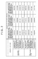
- the air conditioning and hot-water supply system is set to "first operation state" shown in Fig. 2 in the exhaust recovery operation. That is, the hot-water supply compressor 41 is operated, the hot-water supply utilizing side heat exchanger 42 is used as a condenser, the hot-water supply heat source side heat exchanger 44 is not used, and the intermediate heat exchanger 23 is used as an evaporator in the hot-water supply cycle.
- the air conditioning compressor 21 is operated, the air conditioning utilizing side heat exchanger 28 is used as the evaporator, the air conditioning heat source side heat exchanger 24 is not used, and the intermediate heat exchanger 23 is used as a condenser in the air conditioning cycle.
- Arrow marks attached to the respective circuits show directions in which the refrigerants (air conditioning refrigerants, hot-water supply refrigerant) or fluids (water, hot water) flow through the respective circuits.
- Opening/closing valves (35a, 35b, 49b, 49d) of white color and the flow rate control valves (air conditioning refrigerant flow rate adjusting valve 35c, second control valve 35d, hot-water supply refrigerant flow rate adjusting valve 49a, fourth control valve 49c) of white color show states of opening the valves, and the opening/closing valves of black color and the flow rate control valves of black color show states of closing the valves.
- Circular arcs indicated by bold lines show flow paths of the refrigerants and the fluids in the four-way valves (22, 53).
- the outdoor fans air conditioning outdoor fan 25, hot-water supply outdoor fan 45
- the case shows that the outdoor fans are operating
- the outdoor fans are in black color
- the case shows that the outdoor fans are stopping.
- the heat exchangers indicated by broken lines show the heat exchangers which are not used, that is, the heat exchangers through which the refrigerants do not flow
- the heat exchangers indicated by bold lines show the heat exchangers which are used, that is, the heat exchangers through which the refrigerants flow.
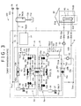
- the control device 1a sets the air conditioning and hot-water supply system 100 to "first operation state" as shown in Fig. 3 . That is, the control device system 1a switches the four-way valve 22 such that the high temperature and high pressure gas refrigerant delivered from the delivery port 21b of the air conditioning compressor 21 flows into the intermediate heat exchanger 23, and the air conditioning refrigerant which flows through the air conditioning utilizing side heat exchanger 28 flows into the suction port 21a of the air conditioning compressor 21.
- the control device 1a closes the air conditioning refrigerant flow rate adjusting valve 35c and the second control valve 35d and stops the air conditioning outdoor fan 25, and closes the hot-water supply refrigerant flow rate adjusting valve 49a and the fourth control valve 49c and stops the hot-water supply outdoor fan 45.
- the air conditioning refrigerant flow rate adjusting valve 35c is made to function as means for blocking the air conditioning refrigerant from the air conditioning heat source side heat exchanger 24 since the air conditioning refrigerant is blocked from flowing to the air conditioning heat source side heat exchanger 24 by closing the air conditioning refrigerant flow rate adjusting valve 35c.
- the air conditioning refrigerant blocking means may be configured to install a blocking valve, not illustrated, at the cooling time air conditioning refrigerant inlet 24a, other than the air conditioning refrigerant flow rate adjusting valve 34c.
- the hot-water supply refrigerant flow rate adjusting valve 49a is made to function as means for blocking the hot-water supply refrigerant from the hot-water supply heat source side heat exchanger 44 since the hot-water supply refrigerant is blocked from flowing into the hot-water supply heat source side heat exchanger 44 by closing the hot-water supply refrigerant flow rate adjusting valve 49a.
- the hot-water supply refrigerant blocking means may be configured to install a blocking valve, not illustrated, at the hot-water supply refrigerant inlet 44a other than the hot-water supply refrigerant flow rate adjusting valve 49a.
- the control device 1a opens the opening/closing valves 35a, 35b, 49b, and 49d.
- the control device 1a opens the air conditioning refrigerant flow rate adjusting valve 35c and the second control valve 35d and operates the air conditioning outdoor fan 25, and opens the hot-water supply refrigerant flow rate adjusting valve 49a and the fourth control valve 49c and operates the hot-water supply outdoor fan 45 as necessary, details thereof will be described later.
- the high temperature and high pressure gas refrigerant delivered from the air conditioning compressor 21 flows into the intermediate heat exchanger 23, and is condensed to liquefy by radiating heat to the low temperature hot-water supply refrigerant.
- the high pressure liquid refrigerant is expanded by reducing the pressure by the air conditioning expansion valve 27 which is opened at a prescribed opening degree after flowing through the air conditioning tank 26, becomes a low temperature and low pressure gas-liquid two-phase refrigerant, and flows into the air conditioning utilizing side heat exchanger 28.
- the gas-liquid two-phase refrigerant which flows in the air conditioning utilizing side heat exchanger 28 is evaporated into the low pressure gas refrigerant by absorbing heat from cold water at a relatively high temperature which flows through the air conditioning cold/hot water circulating circuit 8, and becomes a low pressure gas refrigerant.
- the low pressure gas refrigerant flows into the suction port 21a of the air conditioning air compressor 21 via the four-way valve 22 and becomes the high temperature and high pressure gas refrigerant by being compressed again by the air conditioning compressor 21.
- cold water which radiates heat to the air conditioning refrigerant which flows through the air conditioning utilizing side heat exchanger 28 flows through the air conditioning cold/hot water pipe 55a by the air conditioning cold/hot water circulating pump 52, and flows into the indoor heat exchanger 61.
- heat is exchanged between cold water in the air conditioning cold/hot water circulating circuit 8 and indoor high temperature air of the residence 60, and air of the residence 60 is cooled. That is, the indoor portion of the residence 60 is cooled.
- cold water which flows through the indoor heat exchanger 61 absorbs heat from air of the indoor portion of the residence 60 to elevate temperature thereof.
- the elevated temperature cold water flows through the air conditioning cold/hot water pipes 55b and 55c by the air conditioning cold/hot water pump 52, and is cooled again by radiating heat to the air conditioning refrigerant by the air conditioning utilizing side heat exchanger 28.
- a gas refrigerant which becomes the high temperature and high pressure gas refrigerant by being compressed by the hot-water supply compressor 41 flows into the hot-water supply utilizing side heat exchanger 42.
- the high temperature and high pressure gas refrigerant which flows in the hot-water supply utilizing side heat exchanger 42 is condensed to liquefy by radiating heat to water which flows in the hot-water supply flow path 9.
- the liquefied high pressure liquid refrigerant becomes a low temperature and low pressure gas-liquid two-phase refrigerant by being expanded by reducing a pressure thereof by the hot-water supply expansion valve 43 which is opened at a prescribed opening degree after flowing through the hot-water supply refrigerant tank 46.
- the gas-liquid two-phase refrigerant becomes a low pressure gas refrigerant by being evaporated by absorbing heat from the high temperature air conditioning refrigerant which flows through the intermediate heat exchanger 23 while flowing through the intermediate heat exchanger 23.
- the low pressure gas refrigerant flows into the suction port 41a of the hot-water supply compressor 41, and becomes a high temperature and high pressure gas refrigerant by being compressed again by the hot-water supply compressor 41.
- water which flows into the water inlet 78 flows into the hot-water supply pipe 72, and flows into the hot-water supply utilizing side heat exchanger 42.
- the water becomes water at a high temperature (hot water) by absorbing heat from the hot-water supply refrigerant which flows through the hot-water supply refrigerant circuit 6 by the hot-water supply utilizing side heat exchanger 42.
- the hot water is stored at the hot-water supply tank 70 by flowing through the hot-water supply pipe 73, and is supplied from the hot-water outlet 79 in accordance with a request of a user.
- the air conditioning and hot-water supply system 100 is set to "first operation state" in the exhaust heat recovery operation.
- the heat which is recovered by the air conditioning refrigerant that flows through the air conditioning refrigerant circuit 5 from the indoor portion of the residence 60 is absorbed by the hot-water supply refrigerant that flows through the hot-water supply refrigerant circuit 6 via the intermediate heat exchanger 23, and thereafter, transferred to water that flows through the hot-water supply pipe 72 via the hot-water supply utilizing side heat exchanger 42.
- the heat which is recovered from the indoor portion of the residence 60 can be utilized as a source of heating water which flows through the hot-water supply pipe 72.
- the heat amount which is radiated at the intermediate heat exchanger 23 and the air conditioning heat source side heat exchanger 24 by the air conditioning refrigerant which flows through the air conditioning refrigerant circuit 5 (hereinafter, referred to as air conditioning heat radiating amount) is a heat amount which is recovered by the indoor heat exchanger 61 from the indoor portion of the residence 60. Therefore, the heat amount is determined by a temperature which is set by a user as the indoor temperature of the residence 60 or the outdoor air temperature.
- the heat amount which is needed for boiling water that flows through the hot-water supply pipe 72 (hereinafter, referred to as hot-water supply heat absorbing amount) is determined by a temperature set by a user as a temperature of hot water stored in the hot-water supply tank 70 or a temperature of water supplied from the water inlet 78. Therefore, there is a case where the air conditioning heat radiating amount and the hot-water supply heat absorbing amount do not coincide with other.
- the air conditioning heat radiating amount is larger than the hot-water supply heat absorbing amount (air conditioning heat generating amount > hot-water supply heat absorbing amount) as in a case where a cooling load is high in the air conditioning cycle
- the intermediate heat exchanger 23 when all of the air conditioning refrigerant which flows through the air conditioning refrigerant circuit 5 flows through the intermediate heat exchanger 23, a heat amount which is supplied to water that flows through the hot-water supply pipe 72 via the hot-water supply refrigerant that flows through the hot-water supply refrigerant circuit 6 becomes excessive.
- the air conditioning and hot-water supply system 100 is controlled such that the air conditioning refrigerant which flows through the air conditioning refrigerant circuit 5 is distributed to the intermediate heat exchanger 23 and the air conditioning heat source side heat exchanger 24, and a heat amount which the air conditioning refrigerant radiates at the intermediate heat exchanger 23 becomes equal to the hot-water heat absorbing amount.
- the control device 1a sets the air conditioning and hot-water supply system 100 to "second operation state" shown in Fig. 2 such that the air conditioning heat source side heat exchanger 24 is used as a condenser. Specifically, the control device 1a opens the air conditioning refrigerant flow rate adjusting valve 35c and the second control valve 35d and operates the air conditioning outdoor fan 25 as shown in Fig. 4 . The control device 1a closes the hot-water supply refrigerant flow rate adjusting valve 49a and the fourth control valve 49c and stops the hot-water supply outdoor fan 45.
- the air conditioning and hot-water supply system 100 When the air conditioning and hot-water supply system 100 is set to "second operation state", the high temperature and high pressure gas refrigerant which is delivered from the delivery port 21b of the air conditioning compressor 21 flows into the intermediate heat exchanger 23 and the air conditioning heat source side heat exchanger 24 via the four-way valve 22 in the air conditioning refrigerant circuit 5.
- the high temperature and high pressure gas refrigerant which flows in the intermediate heat exchanger 23 is condensed to liquefy by radiating heat to the hot-water supply refrigerant in the intermediate heat exchanger 23.
- the high temperature and high pressure gas refrigerant which flows into the air conditioning heat source side heat exchanger 24 is condensed to liquefy by radiating heat to the atmosphere.
- the high pressure liquid refrigerant which has been liquefied in the intermediate heat exchanger 23 and the air conditioning heat source side heat exchanger 24 flows into the air conditioning refrigerant tank 26, thereafter, reduces its pressure by the air conditioning expansion valve 27 which is opened at a prescribed opening degree, expanded, becomes a low temperature and low pressure gas-liquid two-phase refrigerant, and flows into the air conditioning utilizing side heat exchanger 28.
- the gas-liquid two-phase refrigerant which flows in the air conditioning utilizing side heat exchanger 28 is evaporated by absorbing heat from cold water at a relatively high temperature which flows through the air conditioning cold/hot water circulating circuit 8, and becomes the low pressure gas refrigerant.
- the low pressure gas refrigerant flows into the suction port 21a of the air conditioning compressor 21 via the four-way valve 22, and becomes the high temperature and high pressure gas refrigerant by being compressed again by the air conditioning compressor 21.
- the high temperature and high pressure gas refrigerant which is delivered from the delivery port 41b of the hot-water supply compressor 41 flows into the hot-water supply utilizing side heat exchanger 42.
- the high temperature and high pressure gas refrigerant which flows in the hot-water supply utilizing side heat exchanger 42 is condensed to liquefy by radiating heat to water which flows in the hot-water supply flow path 9.
- the liquefied high pressure liquid refrigerant flows into the hot-water supply refrigerant tank 46, thereafter, reduces its pressure by the hot-water supply expansion valve 43 which is opened at a prescribed opening degree, expanded, and becomes a low temperature and low pressure gas-liquid two-phase refrigerant.
- the gas-liquid two-phase refrigerant is evaporated by absorbing heat from the high temperature air conditioning refrigerant which flows in the intermediate heat exchanger 23 while flowing in the intermediate heat exchanger 23, and becomes a low pressure gas refrigerant.
- the low pressure gas refrigerant flows into the suction port 41a of the hot-water supply compressor 41, and becomes the high temperature and high pressure gas refrigerant by being compressed again by the hot-water supply compressor 41.
- the control device 1a opens the air conditioning refrigerant flow rate adjusting valve 35c and the second control valve 35d and operates the air conditioning outdoor fan 25, and radiates a portion of the air conditioning heat radiating amount to the atmosphere by the air conditioning heat source side heat exchanger 24. Thereby, it is avoided that a heat amount which is supplied to water that flows through the hot-water supply pipe 72 becomes excessive.
- a condensation temperature "Tca” of the air conditioning refrigerant circuit 5 needs to be higher than an outdoor air temperature "Tao” since heat needs to be radiated to outdoor air.
- the condensation temperature "Tca” of the air conditioning refrigerant circuit 5 needs to be higher than an evaporation temperature "Tee” of the hot-water supply refrigerant circuit 6 since in the exhaust heat recovery operation, heat is absorbed and radiated by exchanging heat by the hot-water supply refrigerant which flows through the hot-water supply refrigerant circuit 6 and the air conditioning refrigerant which flows through the air conditioning refrigerant circuit 5 in the intermediate heat exchanger 23.
- a heat radiating amount (air conditioning heat radiating amount) of the air conditioning refrigerant circuit 5 becomes deficient unless conditions of "Tca > Tao" and “Tca > Tee" are satisfied at the air conditioning heat source side heat exchanger 24 and the intermediate heat exchanger 23.
- a specific weight of the air conditioning refrigerant having the high dryness is large, and therefore, when the air conditioning refrigerant passes to the air conditioning expansion valve 27, a flow speed of the air conditioning refrigerant becomes extremely high. As a result thereof, there poses a problem that an operation of a total of the air conditioning and hot-water supply system 100 is made to be unstable by bringing about a phenomenon of blocking the flow by increasing a flow resistance.
- the control device 1a adjusts a valve opening degree of the air conditioning refrigerant flow rate adjusting valve 35c such that the gas refrigerant flows through the air conditioning heat source side heat exchanger 24 by a flow rate by which all of the high temperature and high pressure gas refrigerant which flows into the air conditioning heat source side heat exchanger 24 is liquefied.
- the control device 1a adjusts the valve opening degree of the air conditioning refrigerant flow rate adjusting valve 35c based on a temperature of the air conditioning refrigerant at the air conditioning heat source side heat exchanger 24.
- control device 1a adjusts the valve opening degree of the air conditioning refrigerant flow rate adjusting valve 35c such that a temperature (temperature of air conditioning heat exchanger outlet) of the air conditioning refrigerant which is to be calculated based on data that is received from the temperature sensor TH22 that is installed at the air conditioning heat source side heat exchanger 24 (vicinity of cooling time air conditioning refrigerant outlet 24b) becomes a previously calculated condensation temperature (target condensation temperature) of the air conditioning refrigerant circuit 5.
- the occurrence of the phenomenon of blocking the flow can be prevented by the configuration by preventing an increase in the flow resistance that is brought about by a deficiency in the heat radiating amount of the air conditioning heat source side heat exchanger 24.
- the hot-water supply heat absorbing amount is larger than the air conditioning heat radiating amount (hot-water supply heat absorbing amount > air conditioning heat radiating amount)
- the intermediate heat exchanger 23 a heat amount which is supplied to water that flows through the hot-water supply pipe 72 via the hot-water supply refrigerant that flows through the hot-water supply refrigerant circuit 6 becomes deficient.
- the hot-water supply heat absorbing amount is larger than the air conditioning heat radiating amount
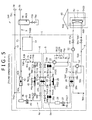
- the control device 1a sets the air conditioning and hot-water supply system 100 to "third operation state" shown in Fig. 2 such that the hot-water supply heat source side heat exchanger 44 is used as the evaporator in a case where the hot-water supply heat absorbing amount is larger than the air conditioning heat radiating amount. Specifically, the control device 1a closes the air conditioning refrigerant flow rate adjusting valve 35c and the second control valve 35d and stops the air conditioning outdoor fan 25 as shown in Fig. 5 . The control device 1a opens the hot-water supply refrigerant flow rate adjusting valve 49a and the fourth control valve 49c and operates the hot-water supply outdoor fan 45.
- the air conditioning and hot-water supply system 100 When the air conditioning and hot-water supply system 100 is set to "third operation state", the high temperature and high pressure gas refrigerant which is delivered from the delivery port 21b of the air conditioning compressor 21 flows into the intermediate heat exchanger 23 via the four-way valve 22 in the air conditioning refrigerant circuit 5.
- the high temperature and high pressure gas refrigerant which flows in the intermediate heat exchanger 23 is condensed to liquefy by radiating heat to the hot-water supply refrigerant in the intermediate heat exchanger 23.
- the high pressure liquid refrigerant which is liquefied at the intermediate heat exchanger 23 flows into the air conditioning refrigerant tank 26, thereafter, reduces its pressure by the air conditioning expansion valve 27 that is opened at a prescribed opening degree, expanded, becomes a low temperature and low pressure gas-liquid two-phase refrigerant, and flows into the air conditioning utilizing side heat exchanger 28.
- the gas-liquid two-phase refrigerant which flows in the air conditioning utilizing side heat exchanger 28 becomes a low pressure gas refrigerant by being evaporated by absorbing heat from cold water at a relatively high temperature which flows through the air conditioning cold/hot water circulating circuit 8.
- the low pressure gas refrigerant flows into the suction port 21a of the air conditioning compressor 21 via the four-way valve 22, and becomes the high temperature and high pressure gas refrigerant by being compressed again by the air conditioning compressor 21.
- the high temperature and high pressure gas refrigerant which is delivered from the delivery port 41b of the hot-water supply compressor 41 flows into the hot-water supply utilizing side heat exchanger 42 in the hot-water supply refrigerant circuit 6.
- the high temperature and high pressure gas refrigerant which flows in the hot-water supply utilizing side heat exchanger 42 is condensed to liquefy by radiating heat to water which flows in the hot-water flow path 9.
- the liquefied high pressure liquid refrigerant flows into the hot-water supply refrigerant tank 46, thereafter, reduces its pressure by the hot-water supply expansion valve 43 which is opened at a prescribed opening degree, expanded, and becomes the low temperature and low pressure gas-liquid two-phase refrigerant.
- a portion of the gas-liquid two-phase refrigerant is evaporated by absorbing heat from the high temperature air conditioning refrigerant which flows in the intermediate heat exchanger 23 while flowing in the intermediate heat exchanger 23, and becomes a low pressure gas refrigerant.
- the low pressure gas refrigerant flows into the suction port 41a of the hot-water supply compressor 41, and becomes the high temperature and high pressure gas refrigerant by being compressed again by the hot-water supply compressor 41.
- the hot-water supply heat absorbing amount is larger than the air conditioning heat radiating amount
- a portion of the hot-water supply refrigerant which flows through the hot-water supply refrigerant circuit 6 is evaporated by absorbing heat at the hot-water supply heat source side heat exchanger 44.
- the hot-water supply heat source side heat exchanger 44 is configured such that the hot-water supply refrigerant flows more easily than in the intermediate heat exchanger 23. Therefore, a large amount of the hot-water supply refrigerant flows into the hot-water supply heat source side heat exchanger 44. An amount of heat exchanged between the air conditioning refrigerant and the hot-water supply refrigerant at the intermediate heat exchanger 23 becomes smaller than a desired heat amount.
- the control device 1a adjusts the valve opening degree of the hot-water supply refrigerant flow rate adjusting valve 49a such that the gas refrigerant flows through the hot-water supply heat source side heat exchanger 44 by a flow rate by which all of the high temperature and high pressure gas refrigerant which flows into the hot-water supply heat source side heat exchanger 44 is evaporated.
- the control device 1a adjusts the valve opening degree of the hot-water supply refrigerant flow rate adjusting valve 49a based on a temperature of the hot-water supply refrigerant in the hot-water supply heat source side heat exchanger 44.
- control device 1a adjusts the valve opening degree of the hot-water supply refrigerant flow rate adjusting valve 49a such that a temperature (hot-water supply heat exchanger outlet temperature) of the hot-water supply refrigerant which is to be calculated based on data received from the temperature sensor TH23 that is included in the hot-water supply heat source side heat exchanger 44 becomes an evaporation temperature (target evaporation temperature) at the hot-water supply refrigerant circuit 6 which is previously calculated.
- a desired heat amount can be exchanged between the air conditioning refrigerant and the hot-water supply refrigerant at the intermediate heat exchanger 23.
- the control device 1a is configured to start the exhaust heat recovery operation of the air conditioning and hot-water supply system 100 when for example, the control device 1a receives an instruction signal from a remote controller (not illustrated) operated by a user.
- a remote controller not illustrated
- the control device 1a is configured to start the exhaust heat recovery operation when hot-water supply operation is carried out by the hot-water supply cycle.
- the control device 1a when the hot-water supply operation by the hot-water supply cycle is started by an operation of a user in a case where the cooling operation is carried out by the air conditioning cycle, the control device 1a is configured to start the exhaust heat recovery operation. Otherwise, for example, there may be constructed a configuration in which the control device 1a automatically starts the exhaust heat recovery operation of the air conditioning and hot-water supply system 100 at previously set prescribed time based on a previously built-in operation program.
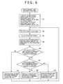
- the control device 1a closes the air conditioning refrigerant flow rate adjusting valve 35c, the second control valve 35d, the hot-water supply refrigerant flow rate adjusting valve 49a, and the fourth control valve 49c (step S1), thereafter, carries out various data receiving processing (step S2). Specifically, the control device 1a receives data indicating a target hot water temperature (boiling temperature), a target hot water amount (flow rate), and a water temperature (water supply temperature) of water supplied from the water inlet 78 in the hot-water supply cycle. The control device 1a receives data indicating a target temperature (set room temperature), a target wind amount, and an indoor temperature in the air conditioning cycle.
- the data indicating the target hot water temperature and the target hot water amount of the hot-water supply cycle is data inputted to the control device 1a from a remote controller (not illustrated) operated by a user, and the data indicating the water supply temperature is data inputted from the temperature sensor TH1.
- the data indicating the target temperature and the target wind amount of the air conditioning cycle is data inputted from the remote controller operated by the user to the control device 1a, and the data indicating the indoor temperature is data inputted from the temperature sensor TH20.
- the control device 1a executes a calculating processing based on the various data received at step S2 (step S3). Specifically, the control device 1a calculates a target hot-water supply capability "Qh”, a target rotational speed of the hot-water supply compressor 41, a target delivery temperature “Td” of the hot-water supply compressor 41, and an input “Whcomp” of the hot-water supply compressor 41 in the hot-water supply cycle. The control device 1a calculates a target air conditioning capability "Qh”, a target rotational speed of the air conditioning compressor 21, a target evaporation temperature “Te” of the air conditioning refrigerant, and an input "Wccomp” of the air conditioning compressor 41 in the air conditioning cycle.
- the control device 1a calculates the hot-water supply heat absorbing amount from a difference between the target hot-water supply capability "Qh” and the input "Wccomp” of the hot-water supply compressor 41 of the hot-water supply cycle, and calculates the air conditioning heat radiating amount from a sum of the target air conditioning capability "Qc” and the input "Wccomp” of the air conditioning compressor 21 of the air conditioning cycle (step S4).
- the control device 1a compares the hot-water supply heat absorbing amount and the air conditioning heat radiating amount calculated at step S4 (step S5), and determines whether the hot-water supply heat absorbing amount and the air conditioning heat radiating amount are equal.
- the control device 1a determines that the hot-water supply heat absorbing amount and the air conditioning heat radiating amount are equal, when a difference between the hot-water supply heat absorbing amount and the air conditioning heat radiating amount falls within a previously set range at step S5.
- step S5 ⁇ Yes the control device 1a sets the air conditioning and hot-water supply system 100 to "first operation state", and executes the exhaust heat recovery operation (step S6). That is, "first operation state” according to the present embodiment is a state of the air conditioning and hot-water supply system 100 when the exhaust heat recovery operation is carried out in a case where the hot-water supply heat absorbing amount and the air conditioning heat radiating amount are equal.
- the control device 1a opens all of the opening/closing valves 35a, 35b, 49b, and 49d which are arranged at outputs and inputs of the intermediate heat exchanger 23 (cooling time air conditioning refrigerant inlet 23a, cooling time air conditioning refrigerant outlet 23b, hot-water supply refrigerant inlet 23c, hot-water refrigerant output 23d) of the intermediate heat exchanger 23 (step S601).
- the control device 1a closes the hot-water supply refrigerant flow rate adjusting valve 49a and the fourth control valve 49c arranged at the outlet and the inlet of the hot-water supply heat source side heat exchanger 44 (hot-water supply refrigerant inlet 44a, hot-water supply refrigerant outlet 44b) and stops the hot-water supply outdoor fan 45 (step S602).
- the control device 1a closes the air conditioning refrigerant flow rate adjusting valve 35c and the second control valve 35d arranged at the outlet and the inlet of the air conditioning heat source heat exchanger 24 (cooling time air conditioning refrigerant inlet 24a, cooling time air conditioning refrigerant outlet 24b) and stops the air conditioning outdoor fan 25 (step S603).
- control device 1a sets the air conditioning and hot-water supply system 100 to carry out the cooling operation and the hot-water supply operation by using only the intermediate heat exchanger 23 as shown in Fig. 3 since the hot-water supply heat absorbing amount and the air conditioning heat radiating amount are equal.
- the control device 1a operates the hot-water supply cycle and the air conditioning cycle in accordance with a result of the calculation at step S3 of Fig. 6 . Specifically, the control device 1a operates the hot-water supply compressor 41 at the target rotational speed calculated at step S3 of Fig. 6 in the hot-water supply cycle, and sets the valve opening degree of the hot-water supply expansion valve 43 such that the delivery temperature of the hot-water supply refrigerant in the hot-water supply cycle becomes the target delivery temperature "Td" (step S604).
- the control device 1a sets the valve opening degree of the hot-water supply expansion valve 43 by referring to the map based on the calculated target delivery temperature "Td".
- the control device 1a operates the air conditioning compressor 21 at the target rotational speed calculated at step S3 of Fig. 6 , sets the valve opening degree of the air conditioning expansion valve 27 such that the evaporation temperature of the air conditioning refrigerator in the air conditioning cycle becomes the target evaporation temperature "Te" (step S605), and the operation returns.
- the control device 1a sets the valve opening degree of the air conditioning expansion valve 27 by referring to the map based on the calculated target evaporation temperature "Te".
- the control device 1a carries out the exhaust heat recovery operation by setting the air conditioning and hot-water supply system 100 to "first operation state" in a case where the hot-water supply heat absorbing amount and the air conditioning heat radiating amount are equal.
- the control device 1a returns the procedure to step S2 of Fig. 6 (step S6 ⁇ step S2), and continues the exhaust heat recovery operation.
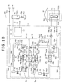
- step S7 the control device 1a compares magnitudes of the hot-water supply heat absorbing amount and the air conditioning heat radiating amount (step S7), sets the air conditioning and hot-water supply system 100 to "second operation state) " when the hot-water supply heat absorbing amount is less than the air conditioning heat radiating amount (step S7 ⁇ Yes), and executes the exhaust heat recovery operation (step S8). That is, the "second operation state” is a state of the air conditioning and hot-water supply system 100 when the exhaust heat recovery operation is carried out in a case where the hot-water supply heat absorbing amount is less than the air conditioning heat radiating amount.
- control device 1a carries out the exhaust heat recovery operation by setting the air conditioning and hot-water supply system 100 to "second operation state" in reference to Fig. 8 .
- the control device 1a opens all of the opening/closing valves 35a, 35b, 49b, and 49d which are arranged at outlets and inlets (cooling time air conditioning refrigerant inlet 23a, cooling time air conditioning refrigerant outlet 23b, hot-water supply refrigerant inlet 23c, hot-water supply refrigerant outlet 23d) of the intermediate heat exchanger 23 (step S801).
- the control device 1a closes the hot-water supply refrigerant flow rate adjusting valve 49a and the fourth control valve 49c which are arranged at the outlet and the inlet (hot-water supply refrigerant inlet 44a, hot-water supply refrigerant outlet 44b) of the hot-water supply heat source side heat exchanger 44, and stops the hot-water supply outdoor fan 45 (step S802).
- the control device 1a opens the air conditioning refrigerant flow rate adjusting valve 35c and the second control valve 35d which are arranged at the outlet and the inlet (cooling time air conditioning refrigerant inlet 24a, cooling time air conditioning refrigerant outlet 24b) of the air conditioning heat source side heat exchanger 24 (step S803).
- control device 1a sets the air conditioning and hot-water supply system 100 such that the cooling operation and the hot-water supply operation are carried out while radiating the heat amount in correspondence with a difference between the air conditioning heat radiating amount and the hot-water supply heat absorbing amount to the atmosphere by the air conditioning heat source side heat exchanger 24 as shown in Fig. 4 since the air conditioning radiating heat amount is larger than the hot-water supply absorbing heat amount.
- control device 1a carries out the receiving processing of respective data (step S804). Specifically, the control device 1a receives data of the hot-water supply heat absorbing amount and the air conditioning heat radiating amount which are calculated at step S4 of Fig. 6 , and data indicating the outdoor air temperature inputted from the temperature sensor TH19. The control device 1a calculates the target evaporation temperature "Te" of the hot-water supply refrigerant in the hot-water supply cycle, and the target condensation temperature "Tc" of the air conditioning refrigerant in the air conditioning cycle based on the received respective data (step S805).
- the control device 1a operates the hot-water supply cycle and the air conditioning cycle in accordance with a result of the calculation at step S805. Specifically, the control device 1a operates the hot-water supply compressor 41 at the target rotational speed in the hot-water supply cycle, and sets the valve opening degree of the hot-water supply expansion valve 43 such that the evaporation temperature of the hot-water supply refrigerant in the hot-water supply cycle becomes the target evaporation temperature "Te".
- the control device 1a operates the air conditioning compressor 21 at the target rotational speed in the air conditioning cycle, sets the rotational speed of the air conditioning outdoor fan 25, and sets the valve opening degree of the air conditioning expansion valve 27 such that the condensation temperature of the air conditioning refrigerant becomes the target condensation temperature "Tc" in the air conditioning cycle (step S806).
- a map showing a relationship between the target evaporation temperature and the valve opening degree of the hot-water supply expansion valve 43 is previously determined, and the control device 1a sets the valve opening degree of the hot-water supply expansion valve 43 by referring to the map based on the calculated target evaporation temperature "Te”.
- a map showing a relationship among the target condensation temperature, the valve opening degree of the air conditioning expansion valve 27, and the rotational speed of the air conditioning outdoor fan 25 is previously determined, and the control device 1a sets the rotational speed of the air conditioning outdoor fan 25 and the valve opening degree of the air conditioning expansion valve 27 by referring to the map based on the calculated target condensation temperature "Tc".
- the control device 1a calculates the temperature of the air conditioning heat exchanger outlet of the air conditioning heat source side heat exchanger 24 based on data which is received from the temperature sensor TH22 (step S807).
- the control device 1a sets the valve opening degree of the air conditioning refrigerant flow rate adjusting valve 35c such that the temperature of the air conditioning heat exchanger outlet of the air conditioning heat source side heat exchanger 24 becomes the calculated target condensation temperature "Tc" (step S808). In this way, the control device 1a adjusts an amount of the air conditioning refrigerant which flows into the air conditioning heat source side heat exchanger 24 by setting the valve opening degree of the air conditioning refrigerant flow rate adjusting valve 35c.
- the control device 1a determines whether the evaporation temperature of the hot-water supply refrigerant in the hot-water supply cycle becomes the target evaporation temperature "Te” (step S809). In a case where the evaporation temperature of the hot-water supply refrigerant in the hot-water supply cycle becomes "Te" II (step S809 ⁇ Yes), the control device 1a determines whether the condensation temperature of the air conditioning refrigerant in the air conditioning cycle becomes the target condensation temperature "Tc" (step S810).
- step S810 ⁇ Yes when the operation of the hot-water supply cycle achieves the target hot-water supply capability "Qh” and the operation of the air conditioning cycle achieves the target air conditioning capability "Qc" (step S811 ⁇ Yes), the control device 1a finishes the procedure of carrying out the exhaust heat recovery operation in the second operation state and the operation returns. However, when the operation of the hot-water supply cycle does not achieve the target hot-water supply capability "Qh” or the operation of the air conditioning cycle does not achieve the target air conditioning capability "Qc" (step S811 ⁇ No), the control device 1a returns the procedure to step S806.
- the control device 1a sets the valve opening degrees of the air conditioning refrigerant flow rate adjusting valve 35c and the second control valve 35d (step 812), and returns the procedure to step S806. Specifically, the control device 1a closes the air conditioning refrigerant flow rate adjusting valve 35c and the second control valve 35d by small amounts at step S812. The control device 1a returns the procedure to step 806, and executes the following procedure.
- step S809 ⁇ No the control device 1a returns the procedure to step S806, and adjusts the valve opening degree of the hot-water supply expansion valve 43 such that the evaporation temperature of the hot-water supply refrigerant in the hot-water supply cycle becomes the target evaporation temperature "Te".
- the control device 1a returns the procedure to step S2 of Fig. 6 (step S8 ⁇ step S2), and continues the exhaust heat recovery operation.
- the control device 1a carries out the exhaust heat recovery operation by setting the air conditioning and hot-water supply system 100 to "second operation state".
- the control device 1a adjusts the valve opening degree of the air conditioning refrigerant flow rate adjusting valve 35c such that the temperature of the air conditioning heat exchanger outlet at the vicinity of the cooling time air conditioning refrigerant outlet 24b of the air conditioning heat source side heat exchanger 24 becomes the calculated condensation temperature (target condensation temperature "Tc").
- step S9 the control device 1a executes the exhaust heat recovery operation by setting the air conditioning and hot-water supply system 100 to "third operation state" (step S9). That is, the "third operation state” is a state of the air conditioning and hot-water supply system 100 when the exhaust heat recovery operation is carried out in the case where the hot-water supply heat absorbing amount is larger than the air conditioning heat radiating amount.
- control device 1a carries out the exhaust heat recovery operation by setting the air conditioning and hot-water supply system 100 to "third operation state" in reference to Fig. 9 .
- the control device 1a opens all of the opening/closing valves 35a, 35b, 49b, and 49d which are arranged at the outlets and the inlets (cooling time air conditioning refrigerant inlet 23a, cooling time air conditioning refrigerant outlet 23b, hot-water supply refrigerant inlet 23c, and hot-water supply refrigerant outlet 23d of the intermediate heat exchanger 23 (step S901).
- the control device 1a opens the hot-water supply refrigerant flow rate adjusting valve 49a and the fourth control valve 49c which are arranged at the outlet and the inlet (hot-water supply refrigerant inlet 44a, hot-water supply refrigerant outlet 44b) of the hot-water supply heat source side heat exchanger 44 (step S902).
- the control device 1a closes the air conditioning refrigerant flow rate adjusting valve 35c and the second control valve 35d which are arranged at the outlet and the inlet (cooling time air conditioning refrigerant inlet 24a, cooling time air conditioning refrigerant outlet 24b of the air conditioning heat source side heat exchanger 24 and stops the air conditioning outdoor fan 25 (step S903).
- control device 1a sets the air conditioning and hot-water supply system 100 such that the cooling operation and the hot-water supply operation are carried out while absorbing a heat amount in correspondence with a difference between the hot-water supply heat absorbing amount and the air conditioning heat radiating amount from the atmosphere at the hot-water supply heat source side heat exchanger 44 as shown in Fig. 5 since the hot-water supply heat absorbing amount is larger than the air conditioning heat radiating amount.
- control device 1a carries out a processing of receiving respective data (step S904). Specifically, the control device 1a receives data of the hot-water supply heat absorbing amount and the air conditioning heat radiating amount which are calculated at step S4 of Fig. 6 , and data indicating an outdoor air temperature inputted from the temperature sensor TH19. The control device 1a calculates the target evaporation temperature "Te" of the hot-water supply refrigerant in the hot-water supply refrigerant cycle and the target condensation temperature "Tc" of the air conditioning refrigerant in the air conditioning cycle based on the received respective data (step S905).
- the control device 1a operates the hot-water supply cycle and the air conditioning cycle in accordance with a result of the calculation at step S905. Specifically, the control device 1a operates the air conditioning compressor 21 at the target rotational speed in the air conditioning cycle, and sets the valve opening degree of the air conditioning expansion valve 27 such that the condensation temperature of the air conditioning refrigerant in the air conditioning cycle becomes the target condensation temperature "Tc".
- the control device 1a operates the hot-water supply compressor 41 at the target rotational speed in the hot-water supply cycle, sets the rotational speed of the hot-water supply outdoor fan 45 such that the evaporation temperature of the hot-water supply refrigerant in the hot-water supply cycle becomes the target evaporation temperature "Te" , and sets the valve opening degree of the hot-water supply expansion valve 43 (step S906).
- a map showing a relationship between the target condensation temperature and the valve opening degree of the air conditioning expansion valve 27 is previously determined, and the control device 1a sets the valve opening degree of the air conditioning expansion valve 27 by referring to the map based on the calculated condensation temperature "Tc".
- a map showing a relationship among the target evaporation temperature, the valve opening degree of the hot-water supply expansion valve 43, and the rotational speed of the hot-water supply outdoor fan 45 is previously determined, and the control device 1a sets the rotational speed of the hot-water supply outdoor fan 45 and the valve opening degree of the hot-water supply expansion valve 43 by referring to the map based on the calculated evaporation temperature "Te".
- the control device 1a calculates the temperature of the hot-water supply heat exchanger outlet of the hot-water supply heat source side heat exchanger 44 based on data received from the temperature sensor TH23 (step S907).
- the control device 1a sets the valve opening degree of the hot-water supply refrigerant flow rate adjusting valve 49a such that the temperature of the hot-water supply heat exchanger outlet of the hot-water supply heat source side heat exchanger 44 becomes the calculated target evaporation temperature "Te" (step S908).
- the control device 1a adjusts an amount of the hot-water supply refrigerant flowing into the hot-water supply heat source side heat exchanger 44 by setting the valve opening degree of the hot-water supply refrigerant flow rate adjusting valve 49a.
- the control device 1a determines whether the condensation temperature of the air conditioning refrigerant in the air conditioning cycle becomes the target condensation temperature "Tc" (step S909). In a case where the condensation temperature of the air conditioning refrigerant in the air conditioning cycle becomes the target condensation temperature "Tc" (step S909 ⁇ Yes), the control device 1a determines whether the evaporation temperature of the hot-water supply refrigerant in the hot-water supply cycle becomes the target evaporation temperature "Te" (step S910).
- step S910 ⁇ Yes when the operation of the hot-water supply cycle achieves the target hot-water supply capability "Qh", and the operation of the air conditioning cycle achieves the target air conditioning capability "Qc" (step S911 ⁇ Yes), the control device 1a finishes the procedure of carrying out the exhaust heat recovery operation in the third operation state and the operation returns.
- step S911 ⁇ No when the operation of the hot-water cycle does not achieve the target hot-water supply capability "Qh” or the operation of the air conditioning cycle does not achieve the target air conditioning capability "Qc" (step S911 ⁇ No), the control device 1a returns the procedure to step S906.
- the control device 1a sets the valve opening degrees of the hot-water supply refrigerant flow rate adjusting valve 49a and the fourth control valve 49c (step S912), and returns the procedure to step S906.
- control device 1a closes the hot-water supply refrigerant flow rate adjusting valve 49a and the fourth control valve 49c by small amounts at step S912.
- the control device 1a returns the procedure to step S906, and executes the following procedure.
- the control device 1a returns from the procedure of setting the air conditioning and hot-water supply system 100 to "third operation state" and carrying out the exhaust heat recovery operation as shown in the flowchart of Fig. 9
- the control device 1a returns the procedure to step S2 of Fig. 6 (step S9 ⁇ step S2), and continues the exhaust heat recovery operation.
- step S909 ⁇ No the control device 1a returns the procedure to step S906, and adjusts the valve opening degree of the air conditioning expansion valve 27 such that the target condensation temperature "Tc" is achieved.
- the control device 1a carries out the exhaust heat recovery operation by setting the air conditioning and hot-water supply system 100 to "third operation state". In this case, the control device 1a adjusts the valve opening degree of the hot-water supply refrigerant flow rate adjusting valve 49a such that the temperature at a vicinity of the hot-water supply refrigerant outlet 44b of the hot-water supply heat source side heat exchanger 44 becomes the previously calculated evaporation temperature (target evaporation temperature).
- All of the hot-water supply refrigerant can be evaporated at the intermediate heat exchanger 23 and the hot-water supply heat source side heat exchanger 44 by the configuration, and a desired heat amount can be exchanged between the air conditioning refrigerant and the hot water supply refrigerant at the intermediate heat exchanger 23.
- the air conditioning refrigerant flow rate adjusting valve 35c is arranged on a side of the cooling time air conditioning refrigerant inlet 24a of the air conditioning heat source side heat exchanger 24 which is arranged in parallel with the intermediate heat exchanger 23.
- the control device 1a sets the valve opening degree of the air conditioning refrigerant flow rate adjusting valve 35c in accordance with the temperature of the air conditioning heat exchanger outlet at the vicinity of the cooling time air conditioning refrigerant outlet 24b of the air conditioning heat source side heat exchanger 24.
- the flow rate of the air conditioning refrigerant which flows in the air conditioning heat source side heat exchanger 24 can be adjusted when the exhaust heat recovery operation is carried out in the case where the air conditioning heat radiating amount is larger than the hot-water supply heat absorbing amount by the configuration.
- the air conditioning refrigerant can sufficiently be cooled at the air conditioning heat source side heat exchanger 24, and all of the air conditioning refrigerant which flows in the air conditioning heat source side heat exchanger 24 can be condensed. In other words, an excessive increase in the flow resistance which is brought about by a deficiency in the heat radiating amount of the air conditioning heat source side heat exchanger 24 can be prevented, and the occurrence of the phenomenon of blocking the flow can be prevented.
- the control device 1a makes the hot-water supply refrigerant flow to the hot-water supply heat source side heat exchanger 44 by opening the hot-water supply refrigerant flow rate adjusting valve 49a and vaporize the hot-water supply refrigerant by heat of the atmosphere.
- the control device 1a sets the valve opening degree of the hot-water supply refrigerant flow rate adjusting valve 49a based on the temperature of the hot-water supply heat exchanger outlet at the hot-water supply refrigerant outlet 44b of the hot-water supply heat source side heat exchanger 44.
- the hot-water supply refrigerant which flows through the hot-water supply refrigerant circuit 6 can preferably be distributed to the intermediate heat exchanger 23 and the hot-water supply heat source side heat exchanger 44 based on the target evaporation temperature in the hot-water supply cycle when the exhaust heat recovery operation is carried out in the case where the hot-water supply heat absorbing amount is larger than the air conditioning heat radiating amount by the configuration. All of the hot-water supply refrigerant can be evaporated by the intermediate heat exchanger 23 and the hot-water supply heat source side heat exchanger 44, and a desired heat amount can be exchanged between the air conditioning refrigerant and the hot-water supply refrigerant at the intermediate heat exchanger 23.
- the air conditioning and hot-water supply system 100 is constructed by a configuration of including the air conditioning refrigerant flow rate adjusting valve 35c on a side of the cooling time air conditioning refrigerant inlet 24a of the air conditioning heat source side heat exchanger 24 and including the hot-water supply refrigerant flow rate adjusting valve 49a on a side of the hot-water supply refrigerant inlet 44a of the hot-water supply heat source side heat exchanger 44.
- an air conditioning refrigerant flow rate adjusting valve 35a1 which can adjust the flow rate is arranged in place of the opening and closing valve 35a (refer to Fig. 1 ) which is arranged at the cooling time air conditioning refrigerant inlet 23a of the intermediate heat exchanger 23, and arranging a hot-water supply refrigerant flow rate adjusting valve 49b1 which can adjust the flow rate in place of the opening/closing valve 49b (refer to Fig. 1 ) which is arranged at the hot-water supply refrigerant inlet 23c of the intermediate heat exchanger 23 as shown in Fig.
- air conditioning heat exchanger outlet temperature measuring means temperature sensor TH24
- hot-water supply heat exchanger outlet temperature measuring means temperature measuring means which measures a temperature of the hot-water supply refrigerant at a vicinity of the hot-water supply refrigerant outlet 23d of the intermediate heat exchanger 23.
- the temperature of the air conditioning refrigerant which is measured by the temperature sensor TH24 is made to be the temperature of the air conditioning heat exchanger outlet of the intermediate heat exchanger 23, and the temperature of the hot-water supply refrigerant which is measured by the temperature sensor TH25 is made to be the temperature of the hot-water supply heat exchanger outlet of the intermediate heat exchanger 23.
- the air conditioning refrigerant flow rate adjusting valve 35c which is arranged at the cooling time air conditioning refrigerant inlet 24a of the air conditioning heat source side heat exchanger 24 may be a control valve (expansion valve) which is not a flow rate adjusting valve.
- the hot-water refrigerant flow rate adjusting valve 49a which is arranged at the hot-water supply refrigerant inlet 44a of the hot-water supply heat source side heat exchanger 44 may be a control valve (expansion valve) which is not a flow rate adjusting valve.
- the control device 1a carries out the exhaust heat recovery operation by setting the air conditioning and hot-water supply system 100 to "second operation state" in accordance with the procedure shown in Fig. 8 when the exhaust heat recovery operation is carried out in the case where the air conditioning heat radiating amount is larger than the hot-water supply heat absorbing amount.
- the control device 1a calculates the temperature of the hot-water supply heat exchanger outlet of the intermediate heat exchanger 23 based on data received from the temperature sensor TH24 in place of the temperature of the air conditioning heat exchanger outlet of the air conditioning heat source side heat exchanger 24 at step S807.
- the control device 1a sets the valve opening degree of the air conditioning refrigerant flow rate adjusting valve 35a1 such that the temperature of the air conditioning heat exchanger outlet of the intermediate heat exchanger 23 becomes the calculated condensation temperature "Tc" at step S808.
- the air conditioning refrigerant can be made to flow to the intermediate heat exchanger 23 which has a small flow path resistance against the air conditioning refrigerant by a preferable flow rate, and the occurrence of the phenomenon of blocking the flow can be prevented by preventing an increase in the flow resistance.
- the control device 1a When the exhaust heat recovery operation is carried out in the case where the hot-water supply heat absorbing amount is larger than the air conditioning heat radiating amount, the control device 1a carries out the exhaust heat recovery operation by setting the air conditioning and hot-water supply system 100 to "third operation state" in accordance with the procedure shown in Fig. 9 . At this occasion, the control device 1a calculates the temperature of the hot-water supply heat exchanger outlet of the intermediate heat exchanger 23 based on data received from the temperature sensor TH25 in place of the temperature of the hot-water supply heat exchanger outlet of the hot-water supply heat source side heat exchanger 44 at step S907.
- the control device 1a sets the valve opening degree of the hot-water supply refrigerant flow rate adjusting valve 49b1 such that the temperature of the hot-water supply heat exchanger outlet of the intermediate heat exchanger 23 becomes the calculated target evaporation temperature "Te" at step S908.
- the hot-water supply refrigerant can be made to flow to the intermediate heat exchanger 23 which has the small flow path resistance against the hot-water supply refrigerant at a preferable flow rate.
- All of the hot-water supply refrigerant can be evaporated at the intermediate heat exchanger 23 and the hot-water supply heat source side heat exchanger 44, and a desired heat amount can be exchanged between the air conditioning refrigerant and the hot-water supply refrigerant at the intermediate heat exchanger 23.
Landscapes
- Engineering & Computer Science (AREA)
- Mechanical Engineering (AREA)
- General Engineering & Computer Science (AREA)
- Physics & Mathematics (AREA)
- Thermal Sciences (AREA)
- Life Sciences & Earth Sciences (AREA)
- Sustainable Development (AREA)
- Chemical & Material Sciences (AREA)
- Combustion & Propulsion (AREA)
- Heat-Pump Type And Storage Water Heaters (AREA)
- Air Conditioning Control Device (AREA)
Abstract
Description
- The present invention relates to an air conditioning and hot-water supply system having multi-heat-sources which is configured with a two-element refrigerating cycle of an air conditioning cycle and a hot-water supply cycle by heat-exchangeably connecting an air conditioning refrigerant circuit and a hot-water supply refrigerant circuit to each other via an intermediate heat exchanger and a control method of an air conditioning and hot-water supply system.
- There is a widely-known air conditioning and hot-water supply system having a multi-heat-sources two-element refrigerating cycle configured by an air conditioning cycle which can carry out a cooling operation and a heating operation and a hot-water supply cycle which can carry out a hot-water supply operation by connecting an air conditioning refrigerant circuit and a hot-water supply refrigerant circuit heat-exchangeably via an intermediate heat exchanger (refer to, for example,
Patent Literatures 1, 2).
Patent Literature 1 discloses a heat pump system which includes a high temperature cycle (hot-water supply cycle) that carries out high temperature outputting, and a medium temperature cycle (air conditioning cycle) that carries out medium temperature outputting or low temperature outputting, and in which an evaporator of the high temperature cycle and a condenser of the medium temperature cycle are configured to be able to exchange heat. According to a technology disclosed inPatent Literature 1, an operation (exhaust heat recovery operation) can be carried out such that exhaust heat of the medium temperature cycle is effectively utilized in the high temperature cycle, and an economic operation can be carried out. - Also,
Patent Literature 2 discloses an air-conditioner which can carry out a heating and cooling operation, a hot-water supply operation, a cool storage operation, a heating and cooling and hot-water supply operation or the like. According to a technology disclosed inPatent Literature 2, the respective operations described above can be switched by including plural switching valves and expansion valves. According to the technology disclosed inPatent Literature 2, the respective operations can efficiently be switched. -
- Patent Literature 1: Japanese Unexamined Patent Application Publication No.
Hei4(1992)-32669 - Patent Literature 2: Japanese Unexamined Patent Application Publication No.
2005-299935 - However, according to the heat pump system disclosed in
Patent Literature 1, exhaust heat of the medium temperature cycle can be utilized as a heat source of the high temperature cycle only when an exhaust heat amount of the medium temperature cycle is larger than a heat absorbing amount of the high temperature cycle. In other words, the exhaust heat of the medium temperature cycle can be utilized for the heat source of the high temperature cycle, and the exhaust heat recovery operation can be carried out only in a case where a load of the medium temperature cycle (air conditioning load) is high.
For example, there is a case where the air-conditioning load is low in an air-conditioning operation for air-conditioning a space having a small internal heat generation such as a space having high insulating performance or a space of few dwellers or the like, or an air-conditioning operation in a state of a low outdoor temperature at nighttime. In such a case, the load of the high temperature cycle (hot-water supply load) may exceed the air conditioning load.
The technology disclosed inPatent Literature 1 poses a problem that a high temperature cycle cannot be operated as requested only by the exhaust heat of the medium temperature cycle in such a case. - Also, the air-conditioner disclosed in
Patent Literature 2 is configured such that a cascade condenser (intermediate heat exchanger) of recovering exhaust heat of a main cycle (air conditioning cycle) and an outdoor heat exchanger (air conditioning heat source side heat exchanger) of the main cycle are arranged in parallel, and the exhaust heat recovery operation can be carried out by delivering heat to a sub cycle (hot-water supply cycle) by recovering exhaust heat of the main cycle by the cascade condenser by simultaneously operating the cascade condenser and the outdoor heat exchanger.
It is necessary to recover a necessary heat amount of the exhaust heat of the main cycle having a large heat amount by the cascade condenser and exhaust a superfluous heat amount from the outdoor heat exchanger for the exhaust heat in order to recover the exhaust heat of the main cycle which carries out the cooling operation by the cascade condenser to utilize as the heat source of the sub cycle. That is, it is necessary to preferably distribute a refrigerant which flows by including the heat of the main cycle to the cascade condenser and the outdoor heat exchanger (heat exchanger for the exhaust heat).
However, Patent Literature 2 does not disclose a technology of preferably distributing the refrigerant to the cascade condenser and the outdoor heat exchanger in the main cycle. - Hence, it is the problem of the present invention to provide an air conditioning and hot-water supply system which can preferably distribute a refrigerant in a cycle having a large heat amount to a heat exchanger for recovering exhaust heat and a heat exchanger for exhaust heat in the exhaust heat recovery operation and a control method of the air conditioning and hot-water supply system.
- In order to resolve the above-described problem, the present invention is an air conditioning and hot-water supply system including an air conditioning refrigerant circuit configuring an air conditioning cycle by circulating an air conditioning refrigerant, a hot-water supply refrigerant circuit configuring a hot-water cycle by circulating a hot-water supply refrigerant, and a control device, further including an intermediate heat exchanger connected in parallel with an air conditioning heat source side heat exchanger for exchanging heat between the air conditioning refrigerant and the atmosphere in the air conditioning refrigerant circuit, and connected in parallel with a hot-water supply heat source side heat exchanger for exchanging heat between the hot-water supply refrigerant and the atmosphere in the hot-water supply refrigerant circuit for exchanging heat between the air conditioning refrigerant and the hot-water supply refrigerant. The air conditioning and hot-water supply system further includes air conditioning refrigerant flow-in amount adjusting means for adjusting an amount of the air conditioning refrigerant flowing into the air conditioning heat source side heat exchanger or the intermediate heat exchanger in a cooling operation by the air conditioning cycle, and means for measuring a temperature of an air conditioning heat exchanger outlet for measuring a temperature of an air conditioning heat exchanger outlet of one of the air conditioning heat source side heat exchanger and the intermediate heat exchanger at which the amount of the air conditioning refrigerant flowing into the air conditioning heat source side heat exchanger or the intermediate heat exchanger is adjusted in the cooling operation, in which the control device calculates an air conditioning heat radiating amount in the air conditioning refrigerant circuit, a hot-water supply heat absorbing amount in the hot-water supply refrigerant circuit, a target condensation temperature at the air conditioning refrigerant circuit, and a target evaporation temperature at the hot-water supply refrigerant circuit in a case where the cooling operation by the air conditioning cycle and a hot-water supply operation by the hot-water cycle are simultaneously executed, and when the air conditioning heat radiating heat amount is larger than the hot-water heat absorbing heat amount, the hot-water supply refrigerant is blocked from flowing into the hot-water supply heat source side heat exchanger by hot-water supply refrigerant blocking means, and the amount of the hot-water supply refrigerant blocking means, and the amount of the air conditioning refrigerant flowing into the air conditioning heat source side heat exchanger or the intermediate heat exchanger is adjusted by controlling the air conditioning refrigerant flow-in amount adjusting means based on the temperature of the air conditioning heat exchanger outlet.
- According to the present invention, there can be provided an air conditioning and hot-water supply system which can preferably distribute a refrigerant in a cycle having a large heat amount to a heat exchanger for recovering exhaust heat and a heat exchanger for exhaust heat in an exhaust heat recovery operation and a control method of the air conditioning and hot-water supply.
-
-
Fig. 1 is a system diagram of an air conditioning and hot-water supply system according to the present embodiment. -
Fig. 2 is a diagram showing a state of an operation mode of an air conditioning and hot-water supply system. -
Fig. 3 is a diagram showing the air conditioning and hot-water supply system which carries out an exhaust heat recovery operation in a first operation state. -
Fig. 4 is a diagram showing the air conditioning and hot-water supply system which carries out the exhaust heat recovery operation in a second operation state. -
Fig. 5 is a diagram showing the air conditioning and hot-water supply system which carries out the exhaust heat recovery operation in a third operation state. -
Fig. 6 is a flowchart showing a procedure of the exhaust heat recovery operation. -
Fig. 7 is a flowchart showing a procedure of the exhaust heat recovery operation in the first operation state. -
Fig. 8 is a flowchart showing a procedure of the exhaust heat recovery operation in the second operation state. -
Fig. 9 is a flowchart showing a procedure of the exhaust heat recovery operation in the third operation state. -
Fig. 10 is a diagram showing an air conditioning and hot-water supply system according to an embodiment including a refrigerant flow control valve at an intermediate heat exchanger. - A detailed explanation will be given of an embodiment of the present invention pertinently in reference to the drawings as follows.
- As shown in
Fig. 1 , an air conditioning and hot-water supply system 100 according to the present embodiment includes an airconditioning refrigerant circuit 5 which carries out an operation by switching a cooling operation and a heating operation by driving an airconditioning refrigerant compressor 21, a hot-watersupply refrigerant circuit 6 which carries out a hot-water supply operation by driving a hot-water supply compressor 41, an air conditioning cold/hot-water circulating circuit 8 which carries out air conditioning of an indoor portion of aresidence 60, a hot-watersupply flow path 9 which carries out hot-water supply by exchanging heat with the hot-watersupply refrigerant circuit 6, and a control device 1a which controls the respective operations. This is a system in which a two-element refrigerating cycle of an air conditioning cycle and a hot-water supply cycle is configured by thermally connecting the airconditioning refrigerant circuit 6 and the hot-watersupply refrigerant circuit 6 via anintermediate heat exchanger 23 which is a heat exchanger for recovering exhaust heat.
Hereinafter, the cooling operation and the heating operation indicate a cooling operation and a heating operation of the air conditioning cycle configured by including the airconditioning refrigerant circuit 5. Also, the hot-water supply operation indicates a hot-water supply operation of the hot-water supply cycle configured by including the hot-watersupply refrigerant circuit 6. - The air conditioning and hot-
water supply system 100 is configured by including aheat pump unit 1 arranged at an outdoor portion of theresidence 60 and anindoor unit 2 arranged at an indoor portion thereof.
Theheat pump unit 1 is integrated with the airconditioning refrigerant circuit 5, the hot-watersupply refrigerant circuit 6, the air conditioning cold/hotwater circulating circuit 8, the hot-watersupply flow path 9, and the control device 1a.
Theindoor unit 2 includes anindoor heat exchanger 61 which carries out heat exchange between indoor air of theresidence 60 and cold/hot water which flows in the air conditioning cold/hotwater circulating circuit 8. - The air
conditioning refrigerant circuit 5 is a circuit which is configured with a refrigerating cycle (air conditioning cycle) by circulating a refrigerant for air conditioning (hereinafter, air conditioning refrigerant). The circuit is configured to connect an air conditioning heat sourceside heat exchanger 24 which exhausts heat by exchanging heat between the atmosphere blown by an air conditioningoutdoor fan 25 and the air conditioning refrigerant to an air conditioning refrigerantmain circuit 5a which is connected with theair conditioning compressor 21 which compresses the air conditioning refrigerant, a four-way valve (air conditioning flow path switching valve) 22 which switches a flow path of the air conditioning refrigerant, theintermediate heat exchanger 23 which exchanges heat between a refrigerant that circulates in the hot-water supply refrigerant circuit 6 (hereinafter, hot-water supply refrigerant) and the air conditioning refrigerant, an airconditioning refrigerant tank 26, an airconditioning expansion valve 27 which reduces a pressure of the air conditioning refrigerant, and an air conditioning utilizingside heat exchanger 28 which exchanges heat between air conditioning cold/hot water that circulates in the air conditioning cold/hotwater circulating circuit 8, and the air conditioning refrigerant which circulates in the airconditioning refrigerant circuit 5 in a ring-like shape by a refrigerant pipe. - In
Fig. 1 , it is configured that heat is exchanged between the air conditioning refrigerant that circulates in the airconditioning refrigerant circuit 5 and the air conditioning cold/hot water that circulates in the air conditioning cold/hotwater circulating circuit 8, and heat is exchanged between the air conditioning cold/hot water and indoor air of theresidence 60 by theindoor heat exchanger 61. However, it may be configured that the air conditioning cold/hot watercircuit circulating circuit 8 is not included and heat is exchanged directly between the air conditioning refrigerant and the indoor air of theresidence 60. - Explaining the air
conditioning refrigerant circuit 5 further in details, the air conditioning heat sourceside heat exchanger 24 is connected by a refrigerant pipe to be in parallel with theintermediate heat exchanger 23 at a position between the four-way valve 22 and the airconditioning expansion valve 27 of the air conditioning refrigerantmain circuit 5a, and an outlet and an inlet of the air conditioning heat sourceside heat exchanger 24 are arranged with afirst control valve 35c and asecond control valve 35d which respectively control a flow rate of the air conditioning refrigerant.
Notation 24a of the air conditioning heat sourceside heat exchanger 24 designates a cooling time air conditioning refrigerant inlet (first air conditioning refrigerant inlet) which becomes an inlet of the air conditioning refrigerant in the cooling operation, andnotation 24b designates a cooling time air conditioning refrigerant outlet (first air conditioning refrigerant outlet) which becomes an outlet of the air conditioning refrigerant in the cooling operation.
Thefirst control valve 35c which is included in the air conditioning and hot-water supply system 100 according to the present embodiment on a side of the cooling time airconditioning refrigerant inlet 24a of the air conditioning heat sourceside heat exchanger 24 is hereinafter referred to as the air conditioning flowrate adjusting valve 35c since thefirst control valve 35c is used as air conditioning refrigerant flow-in amount adjusting means which adjusts a flow-in amount of the air conditioning refrigerant to the air conditioning heat sourceside heat exchanger 24 as described later.
Incidentally, the outlet and the inlet of the air conditioning refrigerant of the air conditioning heat sourceside heat exchanger 24 are reversed in the heating operation of the air conditioning cycle.
Specifically, the cooling time air conditioning refrigerant outlet 20b becomes the inlet of the air conditioning refrigerant and the cooling time airconditioning refrigerant inlet 24a becomes the outlet of the air conditioning refrigerant in the heating operation of the air conditioning cycle.
A refrigerant which is suitable for a condition of use is used from R410a, R134a, HFO1234yf, HFO1234ze, CO2, and propane for the air conditioning refrigerant that circulates in the airconditioning refrigerant circuit 5. - Next, an explanation will be given of respective devices included in the air
conditioning refrigerant circuit 5 mentioned above.
Theair conditioning compressor 21 is preferably a compressor of a variable delivery type which can control delivery. A piston type, a rotary type, a scroll type, a screw type, or a centrifugal type one can be adopted as such a compressor. According to the embodiment, theair conditioning compressor 21 is made to be a scroll type compressor, a delivery thereof can be controlled by an inverter control, and a rotational speed thereof is made variable from a low speed to a high speed. - As the air conditioning utilizing
side heat exchanger 28, a heat exchanger which is configured such that an air conditioning heat transfer pipe in which the air conditioning refrigerant flows and an air conditioning cold/hot water heat transfer pipe in which an antifreezing fluid of water or brine (heat carrying medium on the air conditioning utilizing side) flows are thermally brought into contact with each other, or a plate type heat exchanger can be utilized.
The airconditioning refrigerant tank 26 is made to function as a fluid receiver which adjusts a circulating amount of the air conditioning refrigerant that is changed by switching the flow path of the airconditioning refrigerant circuit 5.
The airconditioning expansion valve 27 is operated as a pressure reducing device and has a function of reducing a pressure of the air conditioning refrigerant to a prescribed pressure by adjusting a valve opening degree. - The air conditioning cold/hot
water circulating circuit 8 is a circuit in which water (heat carrying medium on an air conditioning utilizing side) that exchanges heat with the refrigerant that circulates in the air conditioningrefrigerant circuit 5 flows. This is a circuit configured in a ring-like shape by connecting a four-way valve 53, an air conditioning cold/hotwater circulating pump 52, and theindoor heat exchanger 61 installed at theresidence 60 by an air conditioning cold/hot water pipe 55a having an opening/closing valve 54a, connecting theindoor heat exchanger 61 and the four-way valve 53 by an air conditioning cold/hot water pipe 55b having an opening/closing valve 54b, and connecting the four-way valve 53 and the air conditioning utilizingside heat exchanger 28 by an air conditioning cold/hot water pipe 55c. Water (cold water or hot water) which flows in the air conditioning cold/hotwater circulating circuit 8 cools or heats inside of theresidence 60 by exchanging heat with indoor air of theresidence 60 via theindoor heat exchanger 61. Here, brine of ethylene glycol or the like may be used in place of water as a heat carrying medium on an air conditioning utilizing side which flows in the air conditioning cold/hotwater circulating circuit 8. When brine is used, the brine is applicable also at a cold district. - A phrase of "cold water" or "hot water" is used as water which flows in the air conditioning cold/hot
water circulating circuit 8 in the following explanation. "Cold water" indicates water which flows in the air conditioning cold/hotwater circulating circuit 8 in cooling operation, and "hot water" indicates water which flows in the air conditioning cold/hotwater circulating circuit 8 in heating operation. - The hot-water
supply refrigerant circuit 6 is a circuit which is configured with a refrigerant cycle (hot-water supply cycle) by circulating a hot-water supply refrigerant. The circuit is configured to connect a hot-water supply heat sourceside heat exchanger 44 which exhausts heat by exchanging heat between the atmosphere blown by a hot-water supplyoutdoor fan 45 and the hot-water supply refrigerant to a hot-water supplymain circuit 6a which connects the hot-water supply compressor 41 that compresses the hot-water supply refrigerant, a hot-water supply utilizingside heat exchanger 42 that exchanges heat between water (hot-water supply) that flows in the hot-watersupply flow path 9 and the hot-water supply refrigerant, a hot-watersupply refrigerant tank 46 that is made to function as a fluid receiver that adjusts an amount of the hot-water supply refrigerant, a hot-watersupply expansion valve 43 that reduces a pressure of the hot-water supply refrigerant, and theintermediate heat exchanger 23 which exchanges heat between the air conditioning refrigerant that circulates in the air conditioningrefrigerant circuit 5 and the hot-water supply refrigerant in a ring-like shape by a refrigerant pipe. - Explaining the hot-water
supply refrigerant circuit 6 further in details, the hot-water supply heat sourceside heat exchanger 44 is connected to be in parallel with theintermediate heat exchanger 23 by a refrigerant pipe at a position between the hot-watersupply expansion valve 43 and the hot-water supply compressor 41 of the hot-water supply refrigerantmain circuit 6a. An outlet and an inlet of the hot-water supply heat sourceside heat exchanger 44 are respectively arranged with athird control valve 49a and afourth control valve 49c which respectively control a flow rate of the hot-water supply refrigerant.
In the hot-water supply heat sourceside heat exchanger 44,notation 44a designates a hot-water supply refrigerant inlet (first hot-water supply refrigerant inlet) andnotation 44b designates a hot-water supply refrigerant outlet (first hot-water supply refrigerant outlet).
Thethird control valve 49a which is included on a side of the hot-watersupply refrigerant inlet 44a of the hot-water supply heat sourceside heat exchanger 44 is hereinafter referred to as the hot-water supply refrigerant flowrate adjusting valve 49a since the hot-water supply refrigerant flowrate adjusting valve 49a is used as hot-water supply refrigerant flow-in amount adjusting means that adjusts a flow-in amount of the hot-water supply refrigerant flowing to the hot-water supply heat sourceside heat exchanger 44 in the air conditioning and hot-water supply system 100 according to the present embodiment as described later.
A refrigerant which is suitable for a condition of use is used from R410a, R134a, HFO1234yf, HFO1234ze, CO2, and propane for the hot-water supply refrigerant which circulates in the hot-watersupply refrigerant circuit 6. - Next, an explanation will be given of respective devices included in the hot-water
supply refrigerant circuit 6 described above.
It is preferable for the hot-water supply compressor 41 that a delivery can be controlled by an inverter control and a rotational speed is variable from a low speed to a high speed similar to theair conditioning compressor 21.
The hot-water supply utilizingside heat exchanger 42 which is configured such that s hot-water supply water heat transfer pipe in which water supplied to the hot-watersupply flow path 9 flows and a hot-water supply refrigerant heat transfer pipe in which the hot-water supply refrigerant flows are thermally brought into contact with each other can be utilized although not illustrated.
The hot-watersupply expansion valve 43 can reduce a pressure of the hot-water supply refrigerant to a prescribed pressure by adjusting a valve opening degree. - An outlet and an inlet of the
intermediate heat exchanger 43 of the air conditioningrefrigerant circuit 5 respectively include opening/closing valves
Notation 23a of theintermediate heat exchanger 23 designates a cooling time air conditioning refrigerant inlet (second air conditioning refrigerant inlet) which becomes an inlet of the air conditioning air refrigerant in cooling operation, andnotation 23b designates a cooling time air conditioning outlet (second air conditioning refrigerant outlet) which becomes an outlet of the air conditioning refrigerant in cooling operation.
An opening/closing valve 49b is arranged at a hot-water supply refrigerant inlet (second hot-water supply refrigerant inlet) 23c which becomes an inlet of the hot-water supply refrigerant in hot-water supply operation, and an opening/closing valve 49d is arranged at a hot-water supply refrigerant outlet (second hot-water supply refrigerant outlet) 23d which becomes an outlet of the hot-water supply refrigerant in theintermediate heat exchanger 23.
Incidentally, the outlet and the inlet of the air conditioning refrigerant are reversed in theintermediate heat exchanger 23 in heating operation in the air conditioning cycle.
Specifically, the cooling time air conditioningrefrigerant outlet 23b becomes an inlet of the air conditioning refrigerant, and the cooling time air conditioningrefrigerant inlet 23a becomes an outlet of the air conditioning refrigerant in theintermediate heat exchanger 23 in the heating operation of the air conditioning cycle.
There is a case where a flow path resistance of the air conditioning refrigerant flow path of theintermediate heat exchanger 23 is larger than a flow path resistance of the air conditioning heat sourceside heat exchanger 24 since it is preferable to construct a flow path structure and a path configuration such that the hot-water supply refrigerant which circulates in the hot-watersupply refrigerant circuit 6 can efficiently absorb heat.
Similarly, there is a case where a flow path resistance of the hot-water supply refrigerant flow path of the intermediate heat exchanger is larger than a flow path resistance of the hot-water supply heat sourceside heat exchanger 44 since it is preferable to construct a flow path structure and a path configuration such that the air conditioning refrigerant which circulates in the air conditioningrefrigerant circuit 5 can efficiently radiate heat.
Therefore, the air conditioning heat sourceside heat exchanger 24 and the hot-water supply heat sourceside heat exchanger 44 are constructed by a configuration in which the refrigerants (air conditioning refrigerant, hot-water supply refrigerant) flow more easily than in theintermediate heat exchanger 23. - The hot-water
supply flow path 9 is a flow path in which water as a heat carrying medium on a hot-water supply utilizing side flows, and is a flow path which is configured by connecting awater side inlet 42a of a hot-water supply utilizingside heat exchanger 42 and thewater inlet 78 by a hot-water supply pipe 72, and connecting awater side outlet 42b of the hot-water supply utilizingside heat exchanger 42 and a hot-water outlet 79 by a hot-water supply pipe 73. A hot-water supply tank 70 is provided at the hot-water supply pipe 73, and water supplied from thewater inlet 78 is heated by exchanging heat with the hot-water supply refrigerant at the hot-water supply utilizingside heat exchanger 42, becomes hot water, and thereafter, is stored at the hot-water supply tank 70.
Hot water stored at the hot-water supply tank 70 is supplied from the hot-water outlet 79 to a hot-water supply load side (bathtub, lavatory, kitchen etc.). Adrain pipe 71a and adrain valve 71b are installed at a bottom portion of the hot-water supply tank 70. Thedrain valve 71b is configured to be ordinarily closed, and opened based on an instruction from the control device 1a to thereby discharge hot water stored in the hot-water supply tank 70 to outside by flowing through thedrain pipe 71a. The hot-watersupply flow path 9 is installed with a flow rate sensor (not illustrated) for detecting a flow rate of water or hot water. - The air conditioning and hot-
water supply system 100 includes plural temperature sensors TH1 through TH23. Specifically, thewater side inlet 42a of the hot-water utilizingside heat exchanger 42 is installed with the temperature sensor TH2, and thewater inlet 78 is installed with the temperature sensor TH1, respectively, in order to measure temperatures of water and hot water flowing through the hot-watersupply flow path 9.
An inlet of water (heating timewater side inlet 28a) of the air conditioning utilizingside heat exchanger 28 in heating operation is installed with the temperature sensor TH4, an outlet of water (heating timewater side outlet 28b) of the air conditioning utilizingside heat exchanger 28 in heating operation is installed with the temperature sensor TH3, and arefrigerant outlet 61b of theindoor heat exchanger 61 is installed with the temperature sensor TH5, respectively, in order to measure temperatures of cold water and hot water flowing through the air conditioning cold/hotwater circulating circuit 8.Notation 61a designates a refrigerant inlet of theindoor heat exchanger 61. - A
suction port 41a and adelivery port 41b of the hot-water supply compressor 41 are respectively installed with temperature sensors TH6 and TH7, and an outlet of the hot-watersupply expansion valve 43 is installed with the temperature sensor TH8 in order to measure a temperature of the hot-water supply refrigerant which flow through the hot-watersupply refrigerant circuit 6. The hot-watersupply refrigerant outlet 44b of the hot-water supply heat sourceside heat exchanger 44 is installed with the temperature sensor TH9, and the hot-watersupply refrigerant outlet 23d of theintermediate heat exchanger 23 is installed with the temperature sensor TH10, respectively. - A
suction port 21a and adelivery port 21b of theair conditioning compressor 21 are respectively installed with the temperature sensors TH11 and TH12, the cooling time air conditioningrefrigerant inlet 23a of theintermediate heat exchanger 23 is installed with the temperature sensor TH13, and the cooling time air conditioningrefrigerant outlet 23b is installed with the temperature sensor TH14, respectively, in order to measure a temperature of the air conditioning refrigerant which flows through the air conditioningrefrigerant circuit 5. An outlet of the airconditioning expansion valve 27 in cooling operation is installed with the temperature sensor TH17, the cooling time air conditioningrefrigerant inlet 24a of the air conditioning heat sourceside heat exchanger 24 is installed with the temperature sensor TH15, the cooling time air conditioningrefrigerant outlet 24b is installed with the temperature sensor TH16, and the cooling time air conditioningrefrigerant outlet 28d which becomes an air conditioning refrigerant outlet of the air conditioning utilizingside heat exchanger 28 in cooling operation is installed with the temperature sensor TH18, respectively. Incidentally,notation 28c designates a cooling time air conditioning refrigerant inlet which becomes an inlet of the air conditioning refrigerant to the air conditioning utilizing side heat exchanger in cooling operation. - The air conditioning and hot-
water supply system 100 according to the present embodiment also includes the temperature sensor TH19 which measures an outdoor air temperature, the temperature sensor TH20 which measures an indoor temperature of theresidence 60, and the temperature sensor TH21 which measures a temperature of hot water stored in the hot-water supply tank 70. - The
air conditioning compressor 21 is installed with a rotational speed detecting sensor RA which detects a rotational speed, and the hot-water supply compressor 41 is installed with a rotational speed detecting sensor RH which detects a rotational speed.
The airconditioning expansion valve 27 is installed with a valve opening degree detecting sensor PA which detects a valve opening degree, and the hot-watersupply expansion valve 43 is installed with a valve opening degree detecting sensor PH which detects a valve opening degree. - The air conditioning heat source
side heat exchanger 24 of the air conditioning and hot-water supply system 100 according to the present embodiment includes the temperature sensor TH22 as means for measuring a temperature of the air conditioning heat exchanger outlet for measuring a temperature of the air conditioning refrigerant at a vicinity of the cooling time air conditioningrefrigerant outlet 24b. The vicinity mentioned here indicates a position in a path through which the air conditioning refrigerant flows in the air conditioning heat sourceside heat exchanger 24 which is nearer to the cooling time air conditioningrefrigerant outlet 24b than a middle point of the route.
The temperature of the air conditioning refrigerant which is measured by the temperature sensor TH22 is made to be a temperature of the air conditioning heat exchanger outlet of the air conditioning heat sourceside heat exchanger 24.
Similarly, the hot-water supply heat sourceside heat exchanger 44 is installed with the temperature sensor TH23 as means for measuring a temperature of the hot-water supply heat exchanger outlet for measuring a temperature of the hot-water supply refrigerant at a vicinity of the hot-watersupply refrigerant outlet 44b. The vicinity mentioned here indicates a position of a path through which the hot-water supply refrigerant flows in the hot-water supply heat sourceside heat exchanger 44 which is nearer to the hot-watersupply refrigerant outlet 44b than a middle point of the route.
The temperature of the hot-water supply refrigerant which is measured by the temperature sensor TH23 is made to be a temperature of the hot-water supply heat exchanger outlet of the hot-water supply heat sourceside heat exchanger 44. - The control device 1a is configured to be inputted with an instruction signal from a remote controller (not illustrated), and detecting signals from the temperature sensors TH1 through TH23, the rotational speed detecting sensors RA and RH, and the valve opening degree detecting sensors PA and PH. The control device 1a executes a control which is necessary for operating the air conditioning and hot-
water supply system 100 of operation and stop of theair conditioning compressor 21 and the hot-water supply compressor 41, switching of the four-way valves conditioning expansion valve 27 and the hot-watersupply expansion valve 43, setting of valve opening degrees of the air conditioning refrigerant flowrate adjusting valve 35c, thesecond control valve 35d, the hot-water supply refrigerant flowrate adjusting valve 49a, and thefourth control valve 49c, driving and stop of the air conditioning cold/hotwater circulating pump 52, opening and closing of the opening/closing valves - For example, the air conditioning and hot-
water supply system 100 according to the present embodiment can carry out "exhaust heat recovery operation" which carries out cooling operation in the air conditioning cycle and hot-water supply operation in the hot-water supply cycle while exchanging heat between the air conditioning refrigerant which flows through the air conditioningrefrigerant circuit 5 and the hot-water supply refrigerant which flows through the hot-watersupply refrigerant circuit 6 via theintermediate heat exchanger 23 . - Basically, the air conditioning and hot-water supply system is set to "first operation state" shown in
Fig. 2 in the exhaust recovery operation. That is, the hot-water supply compressor 41 is operated, the hot-water supply utilizingside heat exchanger 42 is used as a condenser, the hot-water supply heat sourceside heat exchanger 44 is not used, and theintermediate heat exchanger 23 is used as an evaporator in the hot-water supply cycle. On the other hand, theair conditioning compressor 21 is operated, the air conditioning utilizingside heat exchanger 28 is used as the evaporator, the air conditioning heat sourceside heat exchanger 24 is not used, and theintermediate heat exchanger 23 is used as a condenser in the air conditioning cycle. - An explanation will be given of flows of refrigerants (air conditioning refrigerant, hot-water supply refrigerant) and a flow of water (heat carrying medium) which flows through the air conditioning cold/hot
water circulating circuit 8 in the exhaust heat recovery operation in reference toFigs. 3 through 5 .
InFigs. 3 through 5 , bold arrow marks attached to the heat exchangers (intermediate heat exchanger 23, air conditioning utilizingside heat exchanger 28, air conditioning heat sourceside heat exchanger 24, hot-water supply utilizingside heat exchanger 42, hot-water supply heat source side heat exchanger 44) show flows of heat. Arrow marks attached to the respective circuits (air conditioningrefrigerant circuit 5, hot-watersupply refrigerant circuit 6, air conditioning cold/hotwater circulating circuit 8, hot-water supply flow path 9) show directions in which the refrigerants (air conditioning refrigerants, hot-water supply refrigerant) or fluids (water, hot water) flow through the respective circuits. Opening/closing valves (35a, 35b, 49b, 49d) of white color and the flow rate control valves (air conditioning refrigerant flowrate adjusting valve 35c,second control valve 35d, hot-water supply refrigerant flowrate adjusting valve 49a,fourth control valve 49c) of white color show states of opening the valves, and the opening/closing valves of black color and the flow rate control valves of black color show states of closing the valves. Circular arcs indicated by bold lines show flow paths of the refrigerants and the fluids in the four-way valves (22, 53). In a case where the outdoor fans (air conditioningoutdoor fan 25, hot-water supply outdoor fan 45) are in white color, the case shows that the outdoor fans are operating, and in a case where the outdoor fans are in black color, the case shows that the outdoor fans are stopping. The heat exchangers (intermediate heat exchanger 23, air conditioning heat sourceside heat exchanger 24, hot-water supply heat source side heat exchanger 44) indicated by broken lines show the heat exchangers which are not used, that is, the heat exchangers through which the refrigerants do not flow, and the heat exchangers indicated by bold lines show the heat exchangers which are used, that is, the heat exchangers through which the refrigerants flow. - When the air conditioning and hot-
water supply system 100 is made to carry out exhaust heat recovery operation, the control device 1a sets the air conditioning and hot-water supply system 100 to "first operation state" as shown inFig. 3 . That is, the control device system 1a switches the four-way valve 22 such that the high temperature and high pressure gas refrigerant delivered from thedelivery port 21b of theair conditioning compressor 21 flows into theintermediate heat exchanger 23, and the air conditioning refrigerant which flows through the air conditioning utilizingside heat exchanger 28 flows into thesuction port 21a of theair conditioning compressor 21.
The control device 1a closes the air conditioning refrigerant flowrate adjusting valve 35c and thesecond control valve 35d and stops the air conditioningoutdoor fan 25, and closes the hot-water supply refrigerant flowrate adjusting valve 49a and thefourth control valve 49c and stops the hot-water supplyoutdoor fan 45.
According to the present embodiment, the air conditioning refrigerant flowrate adjusting valve 35c is made to function as means for blocking the air conditioning refrigerant from the air conditioning heat sourceside heat exchanger 24 since the air conditioning refrigerant is blocked from flowing to the air conditioning heat sourceside heat exchanger 24 by closing the air conditioning refrigerant flowrate adjusting valve 35c. Incidentally, the air conditioning refrigerant blocking means may be configured to install a blocking valve, not illustrated, at the cooling time air conditioningrefrigerant inlet 24a, other than the air conditioning refrigerant flow rate adjusting valve 34c.
Similarly, according to the present embodiment, the hot-water supply refrigerant flowrate adjusting valve 49a is made to function as means for blocking the hot-water supply refrigerant from the hot-water supply heat sourceside heat exchanger 44 since the hot-water supply refrigerant is blocked from flowing into the hot-water supply heat sourceside heat exchanger 44 by closing the hot-water supply refrigerant flowrate adjusting valve 49a. Incidentally, the hot-water supply refrigerant blocking means may be configured to install a blocking valve, not illustrated, at the hot-watersupply refrigerant inlet 44a other than the hot-water supply refrigerant flowrate adjusting valve 49a.
The control device 1a opens the opening/closing valves
Incidentally, although the control device 1a opens the air conditioning refrigerant flowrate adjusting valve 35c and thesecond control valve 35d and operates the air conditioningoutdoor fan 25, and opens the hot-water supply refrigerant flowrate adjusting valve 49a and thefourth control valve 49c and operates the hot-water supplyoutdoor fan 45 as necessary, details thereof will be described later. - The high temperature and high pressure gas refrigerant delivered from the
air conditioning compressor 21 flows into theintermediate heat exchanger 23, and is condensed to liquefy by radiating heat to the low temperature hot-water supply refrigerant. The high pressure liquid refrigerant is expanded by reducing the pressure by the airconditioning expansion valve 27 which is opened at a prescribed opening degree after flowing through theair conditioning tank 26, becomes a low temperature and low pressure gas-liquid two-phase refrigerant, and flows into the air conditioning utilizingside heat exchanger 28. The gas-liquid two-phase refrigerant which flows in the air conditioning utilizingside heat exchanger 28 is evaporated into the low pressure gas refrigerant by absorbing heat from cold water at a relatively high temperature which flows through the air conditioning cold/hotwater circulating circuit 8, and becomes a low pressure gas refrigerant. The low pressure gas refrigerant flows into thesuction port 21a of the airconditioning air compressor 21 via the four-way valve 22 and becomes the high temperature and high pressure gas refrigerant by being compressed again by theair conditioning compressor 21. - At the air conditioning cold/hot
water circulating circuit 8, cold water which radiates heat to the air conditioning refrigerant which flows through the air conditioning utilizingside heat exchanger 28 flows through the air conditioning cold/hot water pipe 55a by the air conditioning cold/hotwater circulating pump 52, and flows into theindoor heat exchanger 61. At theindoor heat exchanger 61, heat is exchanged between cold water in the air conditioning cold/hotwater circulating circuit 8 and indoor high temperature air of theresidence 60, and air of theresidence 60 is cooled. That is, the indoor portion of theresidence 60 is cooled. At this occasion, cold water which flows through theindoor heat exchanger 61 absorbs heat from air of the indoor portion of theresidence 60 to elevate temperature thereof. The elevated temperature cold water flows through the air conditioning cold/hot water pipes hot water pump 52, and is cooled again by radiating heat to the air conditioning refrigerant by the air conditioning utilizingside heat exchanger 28. - At the hot-water
supply refrigerant circuit 6, a gas refrigerant which becomes the high temperature and high pressure gas refrigerant by being compressed by the hot-water supply compressor 41 flows into the hot-water supply utilizingside heat exchanger 42. The high temperature and high pressure gas refrigerant which flows in the hot-water supply utilizingside heat exchanger 42 is condensed to liquefy by radiating heat to water which flows in the hot-watersupply flow path 9. The liquefied high pressure liquid refrigerant becomes a low temperature and low pressure gas-liquid two-phase refrigerant by being expanded by reducing a pressure thereof by the hot-watersupply expansion valve 43 which is opened at a prescribed opening degree after flowing through the hot-watersupply refrigerant tank 46. The gas-liquid two-phase refrigerant becomes a low pressure gas refrigerant by being evaporated by absorbing heat from the high temperature air conditioning refrigerant which flows through theintermediate heat exchanger 23 while flowing through theintermediate heat exchanger 23. The low pressure gas refrigerant flows into thesuction port 41a of the hot-water supply compressor 41, and becomes a high temperature and high pressure gas refrigerant by being compressed again by the hot-water supply compressor 41. - At the hot-water
supply flow path 9, water which flows into thewater inlet 78 flows into the hot-water supply pipe 72, and flows into the hot-water supply utilizingside heat exchanger 42. The water becomes water at a high temperature (hot water) by absorbing heat from the hot-water supply refrigerant which flows through the hot-watersupply refrigerant circuit 6 by the hot-water supply utilizingside heat exchanger 42. The hot water is stored at the hot-water supply tank 70 by flowing through the hot-water supply pipe 73, and is supplied from the hot-water outlet 79 in accordance with a request of a user. - In this way, the air conditioning and hot-
water supply system 100 is set to "first operation state" in the exhaust heat recovery operation. The heat which is recovered by the air conditioning refrigerant that flows through the air conditioningrefrigerant circuit 5 from the indoor portion of theresidence 60 is absorbed by the hot-water supply refrigerant that flows through the hot-watersupply refrigerant circuit 6 via theintermediate heat exchanger 23, and thereafter, transferred to water that flows through the hot-water supply pipe 72 via the hot-water supply utilizingside heat exchanger 42. The heat which is recovered from the indoor portion of theresidence 60 can be utilized as a source of heating water which flows through the hot-water supply pipe 72. - However, the heat amount which is radiated at the
intermediate heat exchanger 23 and the air conditioning heat sourceside heat exchanger 24 by the air conditioning refrigerant which flows through the air conditioning refrigerant circuit 5 (hereinafter, referred to as air conditioning heat radiating amount) is a heat amount which is recovered by theindoor heat exchanger 61 from the indoor portion of theresidence 60. Therefore, the heat amount is determined by a temperature which is set by a user as the indoor temperature of theresidence 60 or the outdoor air temperature.
On the other hand, the heat amount which is needed for boiling water that flows through the hot-water supply pipe 72 (hereinafter, referred to as hot-water supply heat absorbing amount) is determined by a temperature set by a user as a temperature of hot water stored in the hot-water supply tank 70 or a temperature of water supplied from thewater inlet 78. Therefore, there is a case where the air conditioning heat radiating amount and the hot-water supply heat absorbing amount do not coincide with other. - For example, in a case where the air conditioning heat radiating amount is larger than the hot-water supply heat absorbing amount (air conditioning heat generating amount > hot-water supply heat absorbing amount) as in a case where a cooling load is high in the air conditioning cycle, when all of the air conditioning refrigerant which flows through the air conditioning
refrigerant circuit 5 flows through theintermediate heat exchanger 23, a heat amount which is supplied to water that flows through the hot-water supply pipe 72 via the hot-water supply refrigerant that flows through the hot-watersupply refrigerant circuit 6 becomes excessive. Therefore, in a case where the air conditioning heat radiating amount is larger than the hot-water supply heat absorbing amount, it is preferable to construct a configuration in which the air conditioning and hot-water supply system 100 is controlled such that the air conditioning refrigerant which flows through the air conditioningrefrigerant circuit 5 is distributed to theintermediate heat exchanger 23 and the air conditioning heat sourceside heat exchanger 24, and a heat amount which the air conditioning refrigerant radiates at theintermediate heat exchanger 23 becomes equal to the hot-water heat absorbing amount. - Hence, in a case where the air conditioning radiating heat amount is larger than the hot-water absorbing heat amount when the exhaust heat recovery operation is carried out, the control device 1a sets the air conditioning and hot-
water supply system 100 to "second operation state" shown inFig. 2 such that the air conditioning heat sourceside heat exchanger 24 is used as a condenser.
Specifically, the control device 1a opens the air conditioning refrigerant flowrate adjusting valve 35c and thesecond control valve 35d and operates the air conditioningoutdoor fan 25 as shown inFig. 4 . The control device 1a closes the hot-water supply refrigerant flowrate adjusting valve 49a and thefourth control valve 49c and stops the hot-water supplyoutdoor fan 45. - When the air conditioning and hot-
water supply system 100 is set to "second operation state", the high temperature and high pressure gas refrigerant which is delivered from thedelivery port 21b of theair conditioning compressor 21 flows into theintermediate heat exchanger 23 and the air conditioning heat sourceside heat exchanger 24 via the four-way valve 22 in the air conditioningrefrigerant circuit 5. The high temperature and high pressure gas refrigerant which flows in theintermediate heat exchanger 23 is condensed to liquefy by radiating heat to the hot-water supply refrigerant in theintermediate heat exchanger 23. On the other hand, the high temperature and high pressure gas refrigerant which flows into the air conditioning heat sourceside heat exchanger 24 is condensed to liquefy by radiating heat to the atmosphere. The high pressure liquid refrigerant which has been liquefied in theintermediate heat exchanger 23 and the air conditioning heat sourceside heat exchanger 24 flows into the airconditioning refrigerant tank 26, thereafter, reduces its pressure by the airconditioning expansion valve 27 which is opened at a prescribed opening degree, expanded, becomes a low temperature and low pressure gas-liquid two-phase refrigerant, and flows into the air conditioning utilizingside heat exchanger 28. The gas-liquid two-phase refrigerant which flows in the air conditioning utilizingside heat exchanger 28 is evaporated by absorbing heat from cold water at a relatively high temperature which flows through the air conditioning cold/hotwater circulating circuit 8, and becomes the low pressure gas refrigerant. The low pressure gas refrigerant flows into thesuction port 21a of theair conditioning compressor 21 via the four-way valve 22, and becomes the high temperature and high pressure gas refrigerant by being compressed again by theair conditioning compressor 21. - On the other hand, in the hot-water
supply refrigerant circuit 6, the high temperature and high pressure gas refrigerant which is delivered from thedelivery port 41b of the hot-water supply compressor 41 flows into the hot-water supply utilizingside heat exchanger 42. The high temperature and high pressure gas refrigerant which flows in the hot-water supply utilizingside heat exchanger 42 is condensed to liquefy by radiating heat to water which flows in the hot-watersupply flow path 9. The liquefied high pressure liquid refrigerant flows into the hot-watersupply refrigerant tank 46, thereafter, reduces its pressure by the hot-watersupply expansion valve 43 which is opened at a prescribed opening degree, expanded, and becomes a low temperature and low pressure gas-liquid two-phase refrigerant. The gas-liquid two-phase refrigerant is evaporated by absorbing heat from the high temperature air conditioning refrigerant which flows in theintermediate heat exchanger 23 while flowing in theintermediate heat exchanger 23, and becomes a low pressure gas refrigerant. The low pressure gas refrigerant flows into thesuction port 41a of the hot-water supply compressor 41, and becomes the high temperature and high pressure gas refrigerant by being compressed again by the hot-water supply compressor 41. - In this way, in the case where the air conditioning heat radiating amount is larger than the hot-water supply heat absorbing amount, when the exhaust heat recovery operation is carried out, the control device 1a opens the air conditioning refrigerant flow
rate adjusting valve 35c and thesecond control valve 35d and operates the air conditioningoutdoor fan 25, and radiates a portion of the air conditioning heat radiating amount to the atmosphere by the air conditioning heat sourceside heat exchanger 24. Thereby, it is avoided that a heat amount which is supplied to water that flows through the hot-water supply pipe 72 becomes excessive. - Here, a condensation temperature "Tca" of the air conditioning
refrigerant circuit 5 needs to be higher than an outdoor air temperature "Tao" since heat needs to be radiated to outdoor air. On the other hand, the condensation temperature "Tca" of the air conditioningrefrigerant circuit 5 needs to be higher than an evaporation temperature "Tee" of the hot-watersupply refrigerant circuit 6 since in the exhaust heat recovery operation, heat is absorbed and radiated by exchanging heat by the hot-water supply refrigerant which flows through the hot-watersupply refrigerant circuit 6 and the air conditioning refrigerant which flows through the air conditioningrefrigerant circuit 5 in theintermediate heat exchanger 23. That is, in the exhaust heat recovery operation, a heat radiating amount (air conditioning heat radiating amount) of the air conditioningrefrigerant circuit 5 becomes deficient unless conditions of "Tca > Tao" and "Tca > Tee" are satisfied at the air conditioning heat sourceside heat exchanger 24 and theintermediate heat exchanger 23. - For example, there are pointed out a case where the heat radiating heat amount becomes deficient at the air conditioning heat source
side heat exchanger 24 since "Tca ≈ Tao" owing to "Tao << Tee", a case where heat absorbing and radiating amounts becomes deficient at theintermediate heat exchanger 23 since "Tca ≈ Tee" owing to "Tao << Tee" etc.
At this occasion, radiating heat is deficient or heat cannot be radiated in the air conditioning refrigerant, and the air conditioning refrigerant having a high dryness flows out from theintermediate heat exchanger 23 or the air conditioning heat sourceside heat exchanger 24. A specific weight of the air conditioning refrigerant having the high dryness is large, and therefore, when the air conditioning refrigerant passes to the airconditioning expansion valve 27, a flow speed of the air conditioning refrigerant becomes extremely high. As a result thereof, there poses a problem that an operation of a total of the air conditioning and hot-water supply system 100 is made to be unstable by bringing about a phenomenon of blocking the flow by increasing a flow resistance. - Hence, in a case where the air conditioning heat radiating amount is larger than the hot-water supply heat absorbing amount, the control device 1a adjusts a valve opening degree of the air conditioning refrigerant flow
rate adjusting valve 35c such that the gas refrigerant flows through the air conditioning heat sourceside heat exchanger 24 by a flow rate by which all of the high temperature and high pressure gas refrigerant which flows into the air conditioning heat sourceside heat exchanger 24 is liquefied.
The control device 1a adjusts the valve opening degree of the air conditioning refrigerant flowrate adjusting valve 35c based on a temperature of the air conditioning refrigerant at the air conditioning heat sourceside heat exchanger 24.
Specifically, the control device 1a adjusts the valve opening degree of the air conditioning refrigerant flowrate adjusting valve 35c such that a temperature (temperature of air conditioning heat exchanger outlet) of the air conditioning refrigerant which is to be calculated based on data that is received from the temperature sensor TH22 that is installed at the air conditioning heat source side heat exchanger 24 (vicinity of cooling time air conditioningrefrigerant outlet 24b) becomes a previously calculated condensation temperature (target condensation temperature) of the air conditioningrefrigerant circuit 5.
The occurrence of the phenomenon of blocking the flow can be prevented by the configuration by preventing an increase in the flow resistance that is brought about by a deficiency in the heat radiating amount of the air conditioning heat sourceside heat exchanger 24. - On the other hand, in a case where the hot-water supply heat absorbing amount is larger than the air conditioning heat radiating amount (hot-water supply heat absorbing amount > air conditioning heat radiating amount), even when all of the air conditioning refrigerant which flows through the air conditioning
refrigerant circuit 5 flows to theintermediate heat exchanger 23, a heat amount which is supplied to water that flows through the hot-water supply pipe 72 via the hot-water supply refrigerant that flows through the hot-watersupply refrigerant circuit 6 becomes deficient. Therefore, in a case where the hot-water supply heat absorbing amount is larger than the air conditioning heat radiating amount, it is preferable to construct a configuration in which the air conditioning and hot-water supply system 100 is controlled such that all of the air conditioning refrigerant that flows through the air conditioningrefrigerant circuit 5 flows to theintermediate heat exchanger 23, and all of the heat amount included in the air conditioning refrigerant is radiated by theintermediate heat exchanger 23. - Therefore, the control device 1a sets the air conditioning and hot-
water supply system 100 to "third operation state" shown inFig. 2 such that the hot-water supply heat sourceside heat exchanger 44 is used as the evaporator in a case where the hot-water supply heat absorbing amount is larger than the air conditioning heat radiating amount.
Specifically, the control device 1a closes the air conditioning refrigerant flowrate adjusting valve 35c and thesecond control valve 35d and stops the air conditioningoutdoor fan 25 as shown inFig. 5 . The control device 1a opens the hot-water supply refrigerant flowrate adjusting valve 49a and thefourth control valve 49c and operates the hot-water supplyoutdoor fan 45. - When the air conditioning and hot-
water supply system 100 is set to "third operation state", the high temperature and high pressure gas refrigerant which is delivered from thedelivery port 21b of theair conditioning compressor 21 flows into theintermediate heat exchanger 23 via the four-way valve 22 in the air conditioningrefrigerant circuit 5. The high temperature and high pressure gas refrigerant which flows in theintermediate heat exchanger 23 is condensed to liquefy by radiating heat to the hot-water supply refrigerant in theintermediate heat exchanger 23. The high pressure liquid refrigerant which is liquefied at theintermediate heat exchanger 23 flows into the airconditioning refrigerant tank 26, thereafter, reduces its pressure by the airconditioning expansion valve 27 that is opened at a prescribed opening degree, expanded, becomes a low temperature and low pressure gas-liquid two-phase refrigerant, and flows into the air conditioning utilizingside heat exchanger 28. The gas-liquid two-phase refrigerant which flows in the air conditioning utilizingside heat exchanger 28 becomes a low pressure gas refrigerant by being evaporated by absorbing heat from cold water at a relatively high temperature which flows through the air conditioning cold/hotwater circulating circuit 8. The low pressure gas refrigerant flows into thesuction port 21a of theair conditioning compressor 21 via the four-way valve 22, and becomes the high temperature and high pressure gas refrigerant by being compressed again by theair conditioning compressor 21. - On the other hand, the high temperature and high pressure gas refrigerant which is delivered from the
delivery port 41b of the hot-water supply compressor 41 flows into the hot-water supply utilizingside heat exchanger 42 in the hot-watersupply refrigerant circuit 6. The high temperature and high pressure gas refrigerant which flows in the hot-water supply utilizingside heat exchanger 42 is condensed to liquefy by radiating heat to water which flows in the hot-water flow path 9. The liquefied high pressure liquid refrigerant flows into the hot-watersupply refrigerant tank 46, thereafter, reduces its pressure by the hot-watersupply expansion valve 43 which is opened at a prescribed opening degree, expanded, and becomes the low temperature and low pressure gas-liquid two-phase refrigerant. A portion of the gas-liquid two-phase refrigerant is evaporated by absorbing heat from the high temperature air conditioning refrigerant which flows in theintermediate heat exchanger 23 while flowing in theintermediate heat exchanger 23, and becomes a low pressure gas refrigerant. The low pressure gas refrigerant flows into thesuction port 41a of the hot-water supply compressor 41, and becomes the high temperature and high pressure gas refrigerant by being compressed again by the hot-water supply compressor 41.
The low temperature and low pressure gas-liquid two-phase refrigerant which reduces its pressure by the hot-watersupply expansion valve 43, is expanded, and does not flow into theintermediate heat exchanger 23 flows into the hot-water supply heat sourceside heat exchanger 44, is evaporated by absorbing heat from the atmosphere at a relatively high temperature that is blown by the hot-water supplyoutdoor fan 45, becomes the low pressure gas refrigerant, flows into thesuction port 41a of the hot-water supply compressor 41, and becomes the high temperature and high pressure gas refrigerant by being compressed again by the hot-water supply compressor 41. - In this way, in the case where the hot-water supply heat absorbing amount is larger than the air conditioning heat radiating amount, a portion of the hot-water supply refrigerant which flows through the hot-water
supply refrigerant circuit 6 is evaporated by absorbing heat at the hot-water supply heat sourceside heat exchanger 44. As described above, the hot-water supply heat sourceside heat exchanger 44 is configured such that the hot-water supply refrigerant flows more easily than in theintermediate heat exchanger 23. Therefore, a large amount of the hot-water supply refrigerant flows into the hot-water supply heat sourceside heat exchanger 44. An amount of heat exchanged between the air conditioning refrigerant and the hot-water supply refrigerant at theintermediate heat exchanger 23 becomes smaller than a desired heat amount. - Hence, in the case where the hot-water supply heat absorbing amount is larger than the air conditioning heat radiating amount, the control device 1a adjusts the valve opening degree of the hot-water supply refrigerant flow
rate adjusting valve 49a such that the gas refrigerant flows through the hot-water supply heat sourceside heat exchanger 44 by a flow rate by which all of the high temperature and high pressure gas refrigerant which flows into the hot-water supply heat sourceside heat exchanger 44 is evaporated.
The control device 1a adjusts the valve opening degree of the hot-water supply refrigerant flowrate adjusting valve 49a based on a temperature of the hot-water supply refrigerant in the hot-water supply heat sourceside heat exchanger 44.
Specifically, the control device 1a adjusts the valve opening degree of the hot-water supply refrigerant flowrate adjusting valve 49a such that a temperature (hot-water supply heat exchanger outlet temperature) of the hot-water supply refrigerant which is to be calculated based on data received from the temperature sensor TH23 that is included in the hot-water supply heat sourceside heat exchanger 44 becomes an evaporation temperature (target evaporation temperature) at the hot-watersupply refrigerant circuit 6 which is previously calculated.
A desired heat amount can be exchanged between the air conditioning refrigerant and the hot-water supply refrigerant at theintermediate heat exchanger 23. - An explanation will be given of a procedure when the control device 1a makes the air conditioning and hot-
water supply system 100 carry out the exhaust the heat recovery operation in reference toFig. 6 (pertinently in reference toFigs. 1 through 5 ).
The control device 1a is configured to start the exhaust heat recovery operation of the air conditioning and hot-water supply system 100 when for example, the control device 1a receives an instruction signal from a remote controller (not illustrated) operated by a user. For example, when a user enters the indoor portion of theresidence 60 and starts cooling operation (cooling operation of air conditioning cycle) of an air conditioner, not illustrated, by operating a remote controller, the control device 1a is configured to start the exhaust heat recovery operation when hot-water supply operation is carried out by the hot-water supply cycle.
Or, when the hot-water supply operation by the hot-water supply cycle is started by an operation of a user in a case where the cooling operation is carried out by the air conditioning cycle, the control device 1a is configured to start the exhaust heat recovery operation.
Otherwise, for example, there may be constructed a configuration in which the control device 1a automatically starts the exhaust heat recovery operation of the air conditioning and hot-water supply system 100 at previously set prescribed time based on a previously built-in operation program. - When the exhaust heat recovery operation is started, the control device 1a closes the air conditioning refrigerant flow
rate adjusting valve 35c, thesecond control valve 35d, the hot-water supply refrigerant flowrate adjusting valve 49a, and thefourth control valve 49c (step S1), thereafter, carries out various data receiving processing (step S2). Specifically, the control device 1a receives data indicating a target hot water temperature (boiling temperature), a target hot water amount (flow rate), and a water temperature (water supply temperature) of water supplied from thewater inlet 78 in the hot-water supply cycle. The control device 1a receives data indicating a target temperature (set room temperature), a target wind amount, and an indoor temperature in the air conditioning cycle.
The data indicating the target hot water temperature and the target hot water amount of the hot-water supply cycle is data inputted to the control device 1a from a remote controller (not illustrated) operated by a user, and the data indicating the water supply temperature is data inputted from the temperature sensor TH1.
The data indicating the target temperature and the target wind amount of the air conditioning cycle is data inputted from the remote controller operated by the user to the control device 1a, and the data indicating the indoor temperature is data inputted from the temperature sensor TH20. - The control device 1a executes a calculating processing based on the various data received at step S2 (step S3). Specifically, the control device 1a calculates a target hot-water supply capability "Qh", a target rotational speed of the hot-
water supply compressor 41, a target delivery temperature "Td" of the hot-water supply compressor 41, and an input "Whcomp" of the hot-water supply compressor 41 in the hot-water supply cycle.
The control device 1a calculates a target air conditioning capability "Qh", a target rotational speed of theair conditioning compressor 21, a target evaporation temperature "Te" of the air conditioning refrigerant, and an input "Wccomp" of theair conditioning compressor 41 in the air conditioning cycle.
The control device 1a calculates the hot-water supply heat absorbing amount from a difference between the target hot-water supply capability "Qh" and the input "Wccomp" of the hot-water supply compressor 41 of the hot-water supply cycle, and calculates the air conditioning heat radiating amount from a sum of the target air conditioning capability "Qc" and the input "Wccomp" of theair conditioning compressor 21 of the air conditioning cycle (step S4). - The control device 1a compares the hot-water supply heat absorbing amount and the air conditioning heat radiating amount calculated at step S4 (step S5), and determines whether the hot-water supply heat absorbing amount and the air conditioning heat radiating amount are equal. The control device 1a determines that the hot-water supply heat absorbing amount and the air conditioning heat radiating amount are equal, when a difference between the hot-water supply heat absorbing amount and the air conditioning heat radiating amount falls within a previously set range at step S5.
When the hot-water supply heat absorbing amount and the air conditioning heat radiating amount are equal (step S5 → Yes), the control device 1a sets the air conditioning and hot-water supply system 100 to "first operation state", and executes the exhaust heat recovery operation (step S6).
That is, "first operation state" according to the present embodiment is a state of the air conditioning and hot-water supply system 100 when the exhaust heat recovery operation is carried out in a case where the hot-water supply heat absorbing amount and the air conditioning heat radiating amount are equal. - An explanation will be given of a procedure that the control device 1a carries out the exhaust heat recovery operation by setting the air conditioning and hot-
water supply system 100 to "first operation state" in reference toFig. 7 .
The control device 1a opens all of the opening/closing valves refrigerant inlet 23a, cooling time air conditioningrefrigerant outlet 23b, hot-watersupply refrigerant inlet 23c, hot-water refrigerant output 23d) of the intermediate heat exchanger 23 (step S601). The control device 1a closes the hot-water supply refrigerant flowrate adjusting valve 49a and thefourth control valve 49c arranged at the outlet and the inlet of the hot-water supply heat source side heat exchanger 44 (hot-watersupply refrigerant inlet 44a, hot-watersupply refrigerant outlet 44b) and stops the hot-water supply outdoor fan 45 (step S602). The control device 1a closes the air conditioning refrigerant flowrate adjusting valve 35c and thesecond control valve 35d arranged at the outlet and the inlet of the air conditioning heat source heat exchanger 24 (cooling time air conditioningrefrigerant inlet 24a, cooling time air conditioningrefrigerant outlet 24b) and stops the air conditioning outdoor fan 25 (step S603).
That is, the control device 1a sets the air conditioning and hot-water supply system 100 to carry out the cooling operation and the hot-water supply operation by using only theintermediate heat exchanger 23 as shown inFig. 3 since the hot-water supply heat absorbing amount and the air conditioning heat radiating amount are equal. - The control device 1a operates the hot-water supply cycle and the air conditioning cycle in accordance with a result of the calculation at step S3 of
Fig. 6 . Specifically, the control device 1a operates the hot-water supply compressor 41 at the target rotational speed calculated at step S3 ofFig. 6 in the hot-water supply cycle, and sets the valve opening degree of the hot-watersupply expansion valve 43 such that the delivery temperature of the hot-water supply refrigerant in the hot-water supply cycle becomes the target delivery temperature "Td" (step S604).
For example, there may be constructed a configuration in which a map showing a relationship between the target delivery temperature and the valve opening degree of the hot-watersupply expansion valve 43 is previously determined, and the control device 1a sets the valve opening degree of the hot-watersupply expansion valve 43 by referring to the map based on the calculated target delivery temperature "Td".
The control device 1a operates theair conditioning compressor 21 at the target rotational speed calculated at step S3 ofFig. 6 , sets the valve opening degree of the airconditioning expansion valve 27 such that the evaporation temperature of the air conditioning refrigerator in the air conditioning cycle becomes the target evaporation temperature "Te" (step S605), and the operation returns.
For example, there may be constructed a configuration in which a map showing a relationship between the target evaporation temperature and the valve opening degree of the airconditioning expansion valve 27 is previously determined, and the control device 1a sets the valve opening degree of the airconditioning expansion valve 27 by referring to the map based on the calculated target evaporation temperature "Te".
In this way, the control device 1a carries out the exhaust heat recovery operation by setting the air conditioning and hot-water supply system 100 to "first operation state" in a case where the hot-water supply heat absorbing amount and the air conditioning heat radiating amount are equal.
When the operation returns from the procedure of carrying out the exhaust heat recovery operation by setting the air conditioning and hot-water supply system 100 to "first operation state" as shown in the flowchart ofFig. 7 , the control device 1a returns the procedure to step S2 ofFig. 6 (step S6 → step S2), and continues the exhaust heat recovery operation. - The explanation will be returned to step S5 of
Fig. 6 . When the hot-water supply heat absorbing amount and the air conditioning heat radiating amount are not equal (step 55 → No), the control device 1a compares magnitudes of the hot-water supply heat absorbing amount and the air conditioning heat radiating amount (step S7), sets the air conditioning and hot-water supply system 100 to "second operation state) " when the hot-water supply heat absorbing amount is less than the air conditioning heat radiating amount (step S7 → Yes), and executes the exhaust heat recovery operation (step S8).
That is, the "second operation state" is a state of the air conditioning and hot-water supply system 100 when the exhaust heat recovery operation is carried out in a case where the hot-water supply heat absorbing amount is less than the air conditioning heat radiating amount. - An explanation will be given of a procedure in which the control device 1a carries out the exhaust heat recovery operation by setting the air conditioning and hot-
water supply system 100 to "second operation state" in reference toFig. 8 .
The control device 1a opens all of the opening/closing valves refrigerant inlet 23a, cooling time air conditioningrefrigerant outlet 23b, hot-watersupply refrigerant inlet 23c, hot-watersupply refrigerant outlet 23d) of the intermediate heat exchanger 23 (step S801). The control device 1a closes the hot-water supply refrigerant flowrate adjusting valve 49a and thefourth control valve 49c which are arranged at the outlet and the inlet (hot-watersupply refrigerant inlet 44a, hot-watersupply refrigerant outlet 44b) of the hot-water supply heat sourceside heat exchanger 44, and stops the hot-water supply outdoor fan 45 (step S802). The control device 1a opens the air conditioning refrigerant flowrate adjusting valve 35c and thesecond control valve 35d which are arranged at the outlet and the inlet (cooling time air conditioningrefrigerant inlet 24a, cooling time air conditioningrefrigerant outlet 24b) of the air conditioning heat source side heat exchanger 24 (step S803).
That is, the control device 1a sets the air conditioning and hot-water supply system 100 such that the cooling operation and the hot-water supply operation are carried out while radiating the heat amount in correspondence with a difference between the air conditioning heat radiating amount and the hot-water supply heat absorbing amount to the atmosphere by the air conditioning heat sourceside heat exchanger 24 as shown inFig. 4 since the air conditioning radiating heat amount is larger than the hot-water supply absorbing heat amount. - Thereafter, the control device 1a carries out the receiving processing of respective data (step S804). Specifically, the control device 1a receives data of the hot-water supply heat absorbing amount and the air conditioning heat radiating amount which are calculated at step S4 of
Fig. 6 , and data indicating the outdoor air temperature inputted from the temperature sensor TH19. The control device 1a calculates the target evaporation temperature "Te" of the hot-water supply refrigerant in the hot-water supply cycle, and the target condensation temperature "Tc" of the air conditioning refrigerant in the air conditioning cycle based on the received respective data (step S805). - The control device 1a operates the hot-water supply cycle and the air conditioning cycle in accordance with a result of the calculation at step S805.
Specifically, the control device 1a operates the hot-water supply compressor 41 at the target rotational speed in the hot-water supply cycle, and sets the valve opening degree of the hot-watersupply expansion valve 43 such that the evaporation temperature of the hot-water supply refrigerant in the hot-water supply cycle becomes the target evaporation temperature "Te".
The control device 1a operates theair conditioning compressor 21 at the target rotational speed in the air conditioning cycle, sets the rotational speed of the air conditioningoutdoor fan 25, and sets the valve opening degree of the airconditioning expansion valve 27 such that the condensation temperature of the air conditioning refrigerant becomes the target condensation temperature "Tc" in the air conditioning cycle (step S806). - For example, there may be constructed a configuration in which a map showing a relationship between the target evaporation temperature and the valve opening degree of the hot-water
supply expansion valve 43 is previously determined, and the control device 1a sets the valve opening degree of the hot-watersupply expansion valve 43 by referring to the map based on the calculated target evaporation temperature "Te".
There may be constructed a configuration in which a map showing a relationship among the target condensation temperature, the valve opening degree of the airconditioning expansion valve 27, and the rotational speed of the air conditioningoutdoor fan 25 is previously determined, and the control device 1a sets the rotational speed of the air conditioningoutdoor fan 25 and the valve opening degree of the airconditioning expansion valve 27 by referring to the map based on the calculated target condensation temperature "Tc". - The control device 1a calculates the temperature of the air conditioning heat exchanger outlet of the air conditioning heat source
side heat exchanger 24 based on data which is received from the temperature sensor TH22 (step S807).
The control device 1a sets the valve opening degree of the air conditioning refrigerant flowrate adjusting valve 35c such that the temperature of the air conditioning heat exchanger outlet of the air conditioning heat sourceside heat exchanger 24 becomes the calculated target condensation temperature "Tc" (step S808). In this way, the control device 1a adjusts an amount of the air conditioning refrigerant which flows into the air conditioning heat sourceside heat exchanger 24 by setting the valve opening degree of the air conditioning refrigerant flowrate adjusting valve 35c. - The control device 1a determines whether the evaporation temperature of the hot-water supply refrigerant in the hot-water supply cycle becomes the target evaporation temperature "Te" (step S809). In a case where the evaporation temperature of the hot-water supply refrigerant in the hot-water supply cycle becomes "Te" II (step S809 → Yes), the control device 1a determines whether the condensation temperature of the air conditioning refrigerant in the air conditioning cycle becomes the target condensation temperature "Tc" (step S810). In a case where the condensation temperature of the air conditioning refrigerant in the air conditioning cycle becomes the target condensation temperature "Tc" (step S810 → Yes), when the operation of the hot-water supply cycle achieves the target hot-water supply capability "Qh" and the operation of the air conditioning cycle achieves the target air conditioning capability "Qc" (step S811 → Yes), the control device 1a finishes the procedure of carrying out the exhaust heat recovery operation in the second operation state and the operation returns. However, when the operation of the hot-water supply cycle does not achieve the target hot-water supply capability "Qh" or the operation of the air conditioning cycle does not achieve the target air conditioning capability "Qc" (step S811 → No), the control device 1a returns the procedure to step S806.
In a case where the condensation temperature of the air conditioning refrigerant in the air conditioning cycle does not become the target condensation temperature "Tc" (step S810 → No), the control device 1a sets the valve opening degrees of the air conditioning refrigerant flowrate adjusting valve 35c and thesecond control valve 35d (step 812), and returns the procedure to step S806. Specifically, the control device 1a closes the air conditioning refrigerant flowrate adjusting valve 35c and thesecond control valve 35d by small amounts at step S812. The control device 1a returns the procedure to step 806, and executes the following procedure. - On the other hand, in a case where the evaporation temperature of the hot-water refrigerant in the hot-water supply cycle does not become the target evaporation temperature "Te" (step S809 → No), the control device 1a returns the procedure to step S806, and adjusts the valve opening degree of the hot-water
supply expansion valve 43 such that the evaporation temperature of the hot-water supply refrigerant in the hot-water supply cycle becomes the target evaporation temperature "Te".
As shown in the flowchart ofFig. 8 , when the control device 1a returns from the procedure of carrying out the exhaust heat recovery operation by setting the air conditioning and hot-water supply system 100 to "second operation state", the control device 1a returns the procedure to step S2 ofFig. 6 (step S8 → step S2), and continues the exhaust heat recovery operation. - In a case where the air conditioning heat radiating amount is larger than the hot-water supply heat absorbing amount in this way, the control device 1a carries out the exhaust heat recovery operation by setting the air conditioning and hot-
water supply system 100 to "second operation state".
In this case, the control device 1a adjusts the valve opening degree of the air conditioning refrigerant flowrate adjusting valve 35c such that the temperature of the air conditioning heat exchanger outlet at the vicinity of the cooling time air conditioningrefrigerant outlet 24b of the air conditioning heat sourceside heat exchanger 24 becomes the calculated condensation temperature (target condensation temperature "Tc"). An increase in the flow resistance which is brought about by a deficiency in a heat radiating amount of the air conditioning heat sourceside heat exchanger 24 can be prevented and an occurrence of a phenomenon of blocking the flow can be prevented by the configuration. - The explanation will be returned to step S7 of
Fig. 6 . When the hot-water supply heat absorbing amount is larger than the air conditioning heat radiating amount (step S7 → No), the control device 1a executes the exhaust heat recovery operation by setting the air conditioning and hot-water supply system 100 to "third operation state" (step S9). That is, the "third operation state" is a state of the air conditioning and hot-water supply system 100 when the exhaust heat recovery operation is carried out in the case where the hot-water supply heat absorbing amount is larger than the air conditioning heat radiating amount. - An explanation will be given of a procedure in which the control device 1a carries out the exhaust heat recovery operation by setting the air conditioning and hot-
water supply system 100 to "third operation state" in reference toFig. 9 .
The control device 1a opens all of the opening/closing valves refrigerant inlet 23a, cooling time air conditioningrefrigerant outlet 23b, hot-watersupply refrigerant inlet 23c, and hot-watersupply refrigerant outlet 23d of the intermediate heat exchanger 23 (step S901). The control device 1a opens the hot-water supply refrigerant flowrate adjusting valve 49a and thefourth control valve 49c which are arranged at the outlet and the inlet (hot-watersupply refrigerant inlet 44a, hot-watersupply refrigerant outlet 44b) of the hot-water supply heat source side heat exchanger 44 (step S902). The control device 1a closes the air conditioning refrigerant flowrate adjusting valve 35c and thesecond control valve 35d which are arranged at the outlet and the inlet (cooling time air conditioningrefrigerant inlet 24a, cooling time air conditioningrefrigerant outlet 24b of the air conditioning heat sourceside heat exchanger 24 and stops the air conditioning outdoor fan 25 (step S903).
That is, the control device 1a sets the air conditioning and hot-water supply system 100 such that the cooling operation and the hot-water supply operation are carried out while absorbing a heat amount in correspondence with a difference between the hot-water supply heat absorbing amount and the air conditioning heat radiating amount from the atmosphere at the hot-water supply heat sourceside heat exchanger 44 as shown inFig. 5 since the hot-water supply heat absorbing amount is larger than the air conditioning heat radiating amount. - Thereafter, the control device 1a carries out a processing of receiving respective data (step S904). Specifically, the control device 1a receives data of the hot-water supply heat absorbing amount and the air conditioning heat radiating amount which are calculated at step S4 of
Fig. 6 , and data indicating an outdoor air temperature inputted from the temperature sensor TH19. The control device 1a calculates the target evaporation temperature "Te" of the hot-water supply refrigerant in the hot-water supply refrigerant cycle and the target condensation temperature "Tc" of the air conditioning refrigerant in the air conditioning cycle based on the received respective data (step S905). - The control device 1a operates the hot-water supply cycle and the air conditioning cycle in accordance with a result of the calculation at step S905.
Specifically, the control device 1a operates theair conditioning compressor 21 at the target rotational speed in the air conditioning cycle, and sets the valve opening degree of the airconditioning expansion valve 27 such that the condensation temperature of the air conditioning refrigerant in the air conditioning cycle becomes the target condensation temperature "Tc".
The control device 1a operates the hot-water supply compressor 41 at the target rotational speed in the hot-water supply cycle, sets the rotational speed of the hot-water supplyoutdoor fan 45 such that the evaporation temperature of the hot-water supply refrigerant in the hot-water supply cycle becomes the target evaporation temperature "Te" , and sets the valve opening degree of the hot-water supply expansion valve 43 (step S906). - For example, there may be constructed a configuration in which a map showing a relationship between the target condensation temperature and the valve opening degree of the air
conditioning expansion valve 27 is previously determined, and the control device 1a sets the valve opening degree of the airconditioning expansion valve 27 by referring to the map based on the calculated condensation temperature "Tc".
There may be constructed a configuration in which a map showing a relationship among the target evaporation temperature, the valve opening degree of the hot-watersupply expansion valve 43, and the rotational speed of the hot-water supplyoutdoor fan 45 is previously determined, and the control device 1a sets the rotational speed of the hot-water supplyoutdoor fan 45 and the valve opening degree of the hot-watersupply expansion valve 43 by referring to the map based on the calculated evaporation temperature "Te". - The control device 1a calculates the temperature of the hot-water supply heat exchanger outlet of the hot-water supply heat source
side heat exchanger 44 based on data received from the temperature sensor TH23 (step S907).
The control device 1a sets the valve opening degree of the hot-water supply refrigerant flowrate adjusting valve 49a such that the temperature of the hot-water supply heat exchanger outlet of the hot-water supply heat sourceside heat exchanger 44 becomes the calculated target evaporation temperature "Te" (step S908). In this way, the control device 1a adjusts an amount of the hot-water supply refrigerant flowing into the hot-water supply heat sourceside heat exchanger 44 by setting the valve opening degree of the hot-water supply refrigerant flowrate adjusting valve 49a. - The control device 1a determines whether the condensation temperature of the air conditioning refrigerant in the air conditioning cycle becomes the target condensation temperature "Tc" (step S909). In a case where the condensation temperature of the air conditioning refrigerant in the air conditioning cycle becomes the target condensation temperature "Tc" (step S909 → Yes), the control device 1a determines whether the evaporation temperature of the hot-water supply refrigerant in the hot-water supply cycle becomes the target evaporation temperature "Te" (step S910). In a case where the evaporation temperature of the hot-water supply refrigerant in the hot-water supply cycle becomes the target evaporation temperature "Te" (step S910 → Yes), when the operation of the hot-water supply cycle achieves the target hot-water supply capability "Qh", and the operation of the air conditioning cycle achieves the target air conditioning capability "Qc" (step S911 → Yes), the control device 1a finishes the procedure of carrying out the exhaust heat recovery operation in the third operation state and the operation returns. However, when the operation of the hot-water cycle does not achieve the target hot-water supply capability "Qh" or the operation of the air conditioning cycle does not achieve the target air conditioning capability "Qc" (step S911 → No), the control device 1a returns the procedure to step S906.
In a case where the evaporation temperature of the hot-water supply refrigerant in the hot-water supply cycle does not become the target evaporation temperature "Te" (step S910 → No), the control device 1a sets the valve opening degrees of the hot-water supply refrigerant flowrate adjusting valve 49a and thefourth control valve 49c (step S912), and returns the procedure to step S906. Specifically, the control device 1a closes the hot-water supply refrigerant flowrate adjusting valve 49a and thefourth control valve 49c by small amounts at step S912. The control device 1a returns the procedure to step S906, and executes the following procedure.
When the control device 1a returns from the procedure of setting the air conditioning and hot-water supply system 100 to "third operation state" and carrying out the exhaust heat recovery operation as shown in the flowchart ofFig. 9 , the control device 1a returns the procedure to step S2 ofFig. 6 (step S9 → step S2), and continues the exhaust heat recovery operation. - On the other hand, in a case where the target condensation temperature "Tc" is not achieved in the air conditioning cycle (step S909 → No), the control device 1a returns the procedure to step S906, and adjusts the valve opening degree of the air
conditioning expansion valve 27 such that the target condensation temperature "Tc" is achieved. - In a case where the hot-water supply heat absorbing amount is larger than the air conditioning heat radiating amount in this way, the control device 1a carries out the exhaust heat recovery operation by setting the air conditioning and hot-
water supply system 100 to "third operation state".
In this case, the control device 1a adjusts the valve opening degree of the hot-water supply refrigerant flowrate adjusting valve 49a such that the temperature at a vicinity of the hot-watersupply refrigerant outlet 44b of the hot-water supply heat sourceside heat exchanger 44 becomes the previously calculated evaporation temperature (target evaporation temperature). All of the hot-water supply refrigerant can be evaporated at theintermediate heat exchanger 23 and the hot-water supply heat sourceside heat exchanger 44 by the configuration, and a desired heat amount can be exchanged between the air conditioning refrigerant and the hot water supply refrigerant at theintermediate heat exchanger 23. - As described above, in the air conditioning and hot-
water supply system 100 according to the present embodiment, the air conditioning refrigerant flowrate adjusting valve 35c is arranged on a side of the cooling time air conditioningrefrigerant inlet 24a of the air conditioning heat sourceside heat exchanger 24 which is arranged in parallel with theintermediate heat exchanger 23. In a case where the exhaust heat recovery operation is carried out in the cooling operation, the control device 1a sets the valve opening degree of the air conditioning refrigerant flowrate adjusting valve 35c in accordance with the temperature of the air conditioning heat exchanger outlet at the vicinity of the cooling time air conditioningrefrigerant outlet 24b of the air conditioning heat sourceside heat exchanger 24.
The flow rate of the air conditioning refrigerant which flows in the air conditioning heat sourceside heat exchanger 24 can be adjusted when the exhaust heat recovery operation is carried out in the case where the air conditioning heat radiating amount is larger than the hot-water supply heat absorbing amount by the configuration. The air conditioning refrigerant can sufficiently be cooled at the air conditioning heat sourceside heat exchanger 24, and all of the air conditioning refrigerant which flows in the air conditioning heat sourceside heat exchanger 24 can be condensed. In other words, an excessive increase in the flow resistance which is brought about by a deficiency in the heat radiating amount of the air conditioning heat sourceside heat exchanger 24 can be prevented, and the occurrence of the phenomenon of blocking the flow can be prevented. - On the other hand, when the exhaust heat recovery operation is carried out in the case where the hot-water supply heat absorbing amount is larger than the air conditioning heat radiating amount, the control device 1a makes the hot-water supply refrigerant flow to the hot-water supply heat source
side heat exchanger 44 by opening the hot-water supply refrigerant flowrate adjusting valve 49a and vaporize the hot-water supply refrigerant by heat of the atmosphere. At this occasion, the control device 1a sets the valve opening degree of the hot-water supply refrigerant flowrate adjusting valve 49a based on the temperature of the hot-water supply heat exchanger outlet at the hot-watersupply refrigerant outlet 44b of the hot-water supply heat sourceside heat exchanger 44.
The hot-water supply refrigerant which flows through the hot-watersupply refrigerant circuit 6 can preferably be distributed to theintermediate heat exchanger 23 and the hot-water supply heat sourceside heat exchanger 44 based on the target evaporation temperature in the hot-water supply cycle when the exhaust heat recovery operation is carried out in the case where the hot-water supply heat absorbing amount is larger than the air conditioning heat radiating amount by the configuration. All of the hot-water supply refrigerant can be evaporated by theintermediate heat exchanger 23 and the hot-water supply heat sourceside heat exchanger 44, and a desired heat amount can be exchanged between the air conditioning refrigerant and the hot-water supply refrigerant at theintermediate heat exchanger 23. - The air conditioning and hot-
water supply system 100 according to the present embodiment is constructed by a configuration of including the air conditioning refrigerant flowrate adjusting valve 35c on a side of the cooling time air conditioningrefrigerant inlet 24a of the air conditioning heat sourceside heat exchanger 24 and including the hot-water supply refrigerant flowrate adjusting valve 49a on a side of the hot-watersupply refrigerant inlet 44a of the hot-water supply heat sourceside heat exchanger 44. This is because the flow path resistance of theintermediate heat exchanger 23 against the air conditioning refrigerant is larger than the flow path resistance of the air conditioning heat sourceside heat exchanger 24 against the air conditioning refrigerant, and the flow path resistance of theintermediate heat exchanger 23 against the hot-water supply refrigerant is larger than the flow path resistance of the hot-water supply heat sourceside heat exchanger 44 against the hot-water supply refrigerant as described above. - Therefore, there may be constructed a configuration in which an air conditioning refrigerant flow rate adjusting valve 35a1 which can adjust the flow rate is arranged in place of the opening and closing
valve 35a (refer toFig. 1 ) which is arranged at the cooling time air conditioningrefrigerant inlet 23a of theintermediate heat exchanger 23, and arranging a hot-water supply refrigerant flow rate adjusting valve 49b1 which can adjust the flow rate in place of the opening/closing valve 49b (refer toFig. 1 ) which is arranged at the hot-watersupply refrigerant inlet 23c of theintermediate heat exchanger 23 as shown inFig. 10 , in a case where the flow path resistance of theintermediate heat exchanger 23 against the air conditioning refrigerant is smaller than the flow path resistance of the air conditioning heat sourceside heat exchanger 24 against the air conditioning refrigerant, and the flow path resistance of theintermediate heat exchanger 23 against the hot-water supply refrigerant is smaller than the flow path resistance of the hot-water supply heat sourceside heat exchanger 44 against the hot-water supply refrigerant. - In the case of the configuration, it is preferable to construct a configuration of including air conditioning heat exchanger outlet temperature measuring means (temperature sensor TH24) which measures a temperature of the air conditioning refrigerant at a vicinity of the cooling time air conditioning
refrigerant outlet 23b of theintermediate heat exchanger 23, and hot-water supply heat exchanger outlet temperature measuring means (temperature sensor TH25) which measures a temperature of the hot-water supply refrigerant at a vicinity of the hot-watersupply refrigerant outlet 23d of theintermediate heat exchanger 23.
The temperature of the air conditioning refrigerant which is measured by the temperature sensor TH24 is made to be the temperature of the air conditioning heat exchanger outlet of theintermediate heat exchanger 23, and the temperature of the hot-water supply refrigerant which is measured by the temperature sensor TH25 is made to be the temperature of the hot-water supply heat exchanger outlet of theintermediate heat exchanger 23.
In the case of the configuration, there may be constructed a configuration which does not include the temperature sensor TH22 of the air conditioning heat sourceside heat exchanger 24, and the temperature sensor TH23 of the hot-water supply heat sourceside heat exchanger 44.
The air conditioning refrigerant flowrate adjusting valve 35c which is arranged at the cooling time air conditioningrefrigerant inlet 24a of the air conditioning heat sourceside heat exchanger 24 may be a control valve (expansion valve) which is not a flow rate adjusting valve. The hot-water refrigerant flowrate adjusting valve 49a which is arranged at the hot-watersupply refrigerant inlet 44a of the hot-water supply heat sourceside heat exchanger 44 may be a control valve (expansion valve) which is not a flow rate adjusting valve. - The control device 1a carries out the exhaust heat recovery operation by setting the air conditioning and hot-
water supply system 100 to "second operation state" in accordance with the procedure shown inFig. 8 when the exhaust heat recovery operation is carried out in the case where the air conditioning heat radiating amount is larger than the hot-water supply heat absorbing amount.
At this occasion, the control device 1a calculates the temperature of the hot-water supply heat exchanger outlet of theintermediate heat exchanger 23 based on data received from the temperature sensor TH24 in place of the temperature of the air conditioning heat exchanger outlet of the air conditioning heat sourceside heat exchanger 24 at step S807. The control device 1a sets the valve opening degree of the air conditioning refrigerant flow rate adjusting valve 35a1 such that the temperature of the air conditioning heat exchanger outlet of theintermediate heat exchanger 23 becomes the calculated condensation temperature "Tc" at step S808.
Thereby, the air conditioning refrigerant can be made to flow to theintermediate heat exchanger 23 which has a small flow path resistance against the air conditioning refrigerant by a preferable flow rate, and the occurrence of the phenomenon of blocking the flow can be prevented by preventing an increase in the flow resistance. - When the exhaust heat recovery operation is carried out in the case where the hot-water supply heat absorbing amount is larger than the air conditioning heat radiating amount, the control device 1a carries out the exhaust heat recovery operation by setting the air conditioning and hot-
water supply system 100 to "third operation state" in accordance with the procedure shown inFig. 9 .
At this occasion, the control device 1a calculates the temperature of the hot-water supply heat exchanger outlet of theintermediate heat exchanger 23 based on data received from the temperature sensor TH25 in place of the temperature of the hot-water supply heat exchanger outlet of the hot-water supply heat sourceside heat exchanger 44 at step S907. The control device 1a sets the valve opening degree of the hot-water supply refrigerant flow rate adjusting valve 49b1 such that the temperature of the hot-water supply heat exchanger outlet of theintermediate heat exchanger 23 becomes the calculated target evaporation temperature "Te" at step S908.
Thereby, the hot-water supply refrigerant can be made to flow to theintermediate heat exchanger 23 which has the small flow path resistance against the hot-water supply refrigerant at a preferable flow rate. All of the hot-water supply refrigerant can be evaporated at theintermediate heat exchanger 23 and the hot-water supply heat sourceside heat exchanger 44, and a desired heat amount can be exchanged between the air conditioning refrigerant and the hot-water supply refrigerant at theintermediate heat exchanger 23. -
- 1a control device
- 5 air conditioning refrigerant circuit
- 6 hot-water supply refrigerant circuit
- 23 intermediate heat exchanger
- 23a cooling time air conditioning refrigerant inlet (second air conditioning refrigerant inlet)
- 23b cooling time air conditioning refrigerant outlet (second air conditioning refrigerant outlet)
- 23c hot-water supply refrigerant inlet (second hot-water supply refrigerant inlet)
- 23d hot-water supply refrigerant outlet (second hot-water supply refrigerant outlet)
- 24 air conditioning heat source side heat exchanger
- 24a cooling time air conditioning refrigerant inlet (first air conditioning refrigerant inlet)
- 24b cooling time air conditioning refrigerant outlet (first air conditioning refrigerant outlet)
- 35c air conditioning refrigerant flow rate adjusting valve (air conditioning refrigerant flow-in amount adjusting means, air conditioning refrigerant blocking means)
- 35a1 air conditioning refrigerant flow rate adjusting valve (air conditioning refrigerant flow-in amount adjusting means)
- 44 hot-water supply heat source side heat exchanger
- 44a hot-water supply refrigerant inlet (first hot-water supply refrigerant inlet)
- 44b hot-water supply refrigerant outlet (first hot-water supply refrigerant outlet)
- 49a hot-water supply refrigerant flow rate adjusting valve (hot-water refrigerant flow-in amount adjusting means, hot-water supply refrigerant blocking means)
- 49b1 hot-water supply refrigerant flow rate adjusting means (hot-water supply refrigerant flow-in amount adjusting means)
- 100 air conditioning and hot-water supply system
- TH22, TH24 temperature sensors (air conditioning heat exchanger outlet temperature measuring means)
- TH23, TH25 temperature sensors (hot-water supply heat exchanger outlet temperature measuring means)
Claims (13)
- An air conditioning and hot-water supply system comprising:an air conditioning refrigerant circuit configuring an air conditioning cycle by circulating an air conditioning refrigerant, a hot-water supply refrigerant circuit configuring a hot-water supply cycle by circulating a hot-water supply refrigerant, and a control device;an intermediate heat exchanger connected in parallel with an air conditioning heat source side heat exchanger for exchanging heat between the air conditioning refrigerant and the atmosphere in the air conditioning refrigerant circuit, and connected in parallel with a hot-water supply heat source side heat exchanger for exchanging heat between the hot-water supply refrigerant and the atmosphere in the hot-water supply refrigerant circuit for exchanging heat between the air conditioning refrigerant and the hot-water supply refrigerant;an air conditioning refrigerant flow-in amount adjusting means for adjusting an amount of the air conditioning refrigerant flowing into the air conditioning heat source side heat exchanger or the intermediate heat exchanger in a cooling operation by the air conditioning cycle; anda means for measuring a temperature of an air conditioning heat exchanger outlet for measuring a temperature of an air conditioning heat exchanger outlet of one of the air conditioning heat source side heat exchanger and the intermediate heat exchanger at which the amount of the air conditioning refrigerant flowing into the air conditioning heat source side heat exchanger or the intermediate heat exchanger is adjusted in the cooling operation;wherein the control device calculates an air conditioning heat radiating amount in the air conditioning refrigerant circuit, a hot-water supply heat absorbing amount in the hot-water supply refrigerant circuit, a target condensation temperature at the air conditioning refrigerant circuit, and a target evaporation temperature at the hot-water supply refrigerant circuit in a case where the cooling operation by the air conditioning cycle and a hot-water supply operation by the hot-water supply cycle are simultaneously executed; andwherein when the air conditioning heat radiating amount is larger than the hot-water supply heat absorbing amount, the hot-water supply refrigerant is blocked from flowing into the hot-water supply heat source side heat exchanger by hot-water supply refrigerant blocking means, and the amount of the hot-water supply refrigerant blocking means, and the amount of the air conditioning refrigerant flowing into the air conditioning heat source side heat exchanger or the intermediate heat exchanger is adjusted by controlling the air conditioning refrigerant flow-in amount adjusting means based on the temperature of air conditioning heat exchanger outlet.
- The air conditioning and hot-water supply system according to claim 1, wherein the control device adjusts the amount of the air conditioning refrigerant flowing into the air conditioning heat source side heat exchanger or the intermediate heat exchanger such that the temperature of the air conditioning heat exchanger outlet becomes the target condensation temperature.
- The air conditioning and hot-water supply system according to claim 1, wherein the air conditioning refrigerant flow-in amount adjusting means is an air conditioning flow rate adjusting valve;
wherein as a configuration of a case where a flow path resistance of the air conditioning heat source side heat exchanger against the air conditioning refrigerant is smaller than a flow path resistance of the intermediate heat exchanger against the air conditioning refrigerant, the air conditioning refrigerant flow rate adjusting valve is included at a first air conditioning inlet which becomes an inlet of the air conditioning refrigerant to the air conditioning heat source side heat exchanger in the cooling operation, and the means for measuring the temperature of the air conditioning heat exchanger outlet is included at a vicinity of a first air conditioning refrigerant outlet which becomes an outlet of the air conditioning refrigerant from the air conditioning heat source side heat exchanger in the cooling operation; and
wherein the control device adjusts the amount of the air conditioning refrigerant flowing to the air conditioning heat source side heat exchanger by adjusting a valve opening degree of the air conditioning refrigerant flow rate adjusting valve. - The air conditioning and hot-water supply system according to claim 2, wherein the air conditioning refrigerant flow-in amount adjusting means is an air conditioning flow rate adjusting valve;
wherein as a configuration of a case where a flow path resistance of the air conditioning heat source side heat exchanger against the air conditioning refrigerant is smaller than a flow path resistance of the intermediate heat exchanger against the air conditioning refrigerant, the air conditioning refrigerant flow rate adjusting valve is included at a first air conditioning inlet which becomes an inlet of the air conditioning refrigerant to the air conditioning heat source side heat exchanger in the cooling operation, and the means for measuring the temperature of the air conditioning heat exchanger outlet is included at a vicinity of a first air conditioning refrigerant outlet which becomes an outlet of the air conditioning refrigerant from the air conditioning heat source side heat exchanger in the cooling operation; and
wherein the control device adjusts the amount of the air conditioning refrigerant flowing to the air conditioning heat source side heat exchanger by adjusting a valve opening degree of the air conditioning refrigerant flow rate adjusting valve. - The air conditioning and hot-water supply system according to claim 1, wherein the air conditioning refrigerant flow-in amount adjusting means is an air conditioning refrigerant flow rate adjusting valve;
wherein as a configuration of a case where a flow path resistance of the intermediate heat exchanger against the air conditioning refrigerant is smaller than a flow path resistance of the air conditioning heat source side heat exchanger against the air conditioning refrigerant, the air conditioning refrigerant flow rate adjusting valve is included at a second air conditioning refrigerant inlet which becomes an inlet of the air conditioning refrigerant to the intermediate heat exchanger in the cooling operation, and the means for measuring the temperature of the heat exchanger outlet is included at a vicinity of a second air conditioning refrigerant outlet which becomes an outlet of the air conditioning refrigerant from the intermediate heat exchanger in the cooling operation; and
wherein the control device adjusts the amount of the air conditioning refrigerant flowing to the intermediate heat exchanger by adjusting a valve opening degree of the air conditioning refrigerant flow rate adjusting valve. - The air conditioning and hot-water supply system according to claim 2, wherein the air conditioning refrigerant flow-in amount adjusting means is an air conditioning refrigerant flow rate adjusting valve;
wherein as a configuration of a case where a flow path resistance of the intermediate heat exchanger against the air conditioning refrigerant is smaller than a flow path resistance of the air conditioning heat source side heat exchanger against the air conditioning refrigerant, the air conditioning refrigerant flow rate adjusting valve is included at a second air conditioning refrigerant inlet which becomes an inlet of the air conditioning refrigerant to the intermediate heat exchanger in the cooling operation, and the means for measuring the temperature of the heat exchanger outlet is included at a vicinity of a second air conditioning refrigerant outlet which becomes an outlet of the air conditioning refrigerant from the intermediate heat exchanger in the cooling operation; and
wherein the control device adjusts the amount of the air conditioning refrigerant flowing to the intermediate heat exchanger by adjusting a valve opening degree of the air conditioning refrigerant flow rate adjusting valve. - The air conditioning and hot-water supply system according to any one of Claim 1 through Claim 6, further comprising:a hot-water supply refrigerant flow-in amount adjusting means for adjusting an amount of the hot-water supply refrigerant flowing to the hot-water supply heat source side heat exchanger or the intermediate heat exchanger in a hot-water supply operation by the hot-water supply cycle; anda means for measuring a temperature of a hot-water supply heat exchanger outlet for measuring a temperature of a hot-water supply heat exchanger outlet of one of the hot-water supply heat source side heat exchanger and the intermediate heat exchanger at which an amount of the hot-water supply refrigerant flowing to the hot-water supply heat source side heat exchanger or the intermediate heat exchange is adjusted in the hot-water supply operation,wherein the control device blocks the air conditioning refrigerant from flowing to the air conditioning heat source side heat exchanger by air conditioning refrigerant blocking means, and adjusts an amount of the hot-water supply refrigerant flowing to the hot-water supply heat exchanger or the intermediate heat exchanger by controlling the hot-water refrigerant flow-in amount adjusting means based on the temperature of the hot-water heat exchanger outlet when the hot-water heat absorbing amount is larger than the air conditioning heat radiating amount in a case where the cooling operation by the air conditioning cycle and the hot-water supply operation by the hot-water supply cycle are simultaneously executed.
- The air conditioning and hot-water supply system according to claim 7, wherein the control device adjusts the amount of the hot-water supply refrigerant flowing into the hot-water supply heat source side heat exchanger or the intermediate heat exchanger such that the temperature of the hot-water supply heat exchanger outlet becomes the target evaporation temperature.
- The air conditioning and hot-water supply system according to claim 7, wherein the hot-water supply refrigerant flow-in amount adjusting means is a hot-water supply refrigerant flow rate adjusting valve;
wherein as a configuration in a case where a flow resistance of the hot-water supply heat source side heat exchanger against the hot-water supply refrigerant is smaller than a flow path resistance of the intermediate heat exchanger against the hot-water supply refrigerant, the hot-water supply refrigerant flow rate adjusting valve is included at a first hot-water supply refrigerant inlet which becomes an inlet of the hot-water supply refrigerant to the hot-water supply heat source side heat exchanger in the hot-water supply operation, and the means for measuring the temperature of the hot-water supply heat exchanger outlet is included at a vicinity of a first hot-water supply refrigerant outlet which becomes an outlet of the hot-water supply refrigerant from the hot-water supply heat source side heat exchanger in the hot-water supply operation, and
wherein the control device adjusts an amount of the hot-water supply refrigerant flowing into the hot-water supply heat source side heat exchanger by adjusting a valve opening degree of the hot-water supply refrigerant flow rate adjusting valve. - The air conditioning and hot-water supply system according to claim 8, wherein the hot-water supply refrigerant flow-in amount adjusting means is a hot-water supply refrigerant flow rate adjusting valve,
wherein as a configuration in a case where a flow resistance of the hot-water supply heat source side heat exchanger against the hot-water supply refrigerant is smaller than a flow path resistance of the intermediate heat exchanger against the hot-water supply refrigerant, the hot-water supply refrigerant flow rate adjusting valve is included at a first hot-water supply refrigerant inlet which becomes an inlet of the hot-water supply refrigerant to the hot-water supply heat source side heat exchanger in the hot-water supply operation, and means for measuring the temperature of the hot-water supply heat exchanger outlet is included at a vicinity of a first hot-water supply refrigerant outlet which becomes an outlet of the hot-water supply refrigerant from the hot-water supply heat source side heat exchanger in the hot-water supply operation, and
wherein the control device adjusts an amount of the hot-water supply refrigerant flowing into the hot-water supply heat source side heat exchanger by adjusting a valve opening degree of the hot-water supply refrigerant flow rate adjusting valve. - The air conditioning and hot-water supply system according to claim 7, wherein the hot-water supply refrigerant flow-in amount adjusting means is a hot-supply refrigerant flow rate adjusting valve,
wherein as a configuration of a case where a flow path resistance of the intermediate heat exchanger against the hot-water supply refrigerant is smaller than a flow path resistance of the hot-water supply heat source side heat exchanger against the hot-water supply refrigerant, the hot-water refrigerant flow rate adjusting valve is included at a second hot-water supply refrigerant outlet which becomes an inlet of the hot-water supply refrigerant to the intermediate heat exchanger in the hot-water operation, and the means for measuring the temperature of the hot-water supply heat exchanger outlet is included at a vicinity of a second hot-water supply refrigerant outlet which becomes an outlet of the hot-water supply refrigerant from the intermediate heat exchanger in the hot-water operation, and
wherein the control device adjusts an amount of the hot-water supply refrigerant flowing to the intermediate heat exchanger by adjusting a valve opening degree of the hot-water supply refrigerant flow rate adjusting valve. - The air conditioning and hot-water supply system according to claim 8, wherein the hot-water supply refrigerant flow-in amount adjusting means is a hot-water supply refrigerant flow rate adjusting valve,
wherein as a configuration of a case where a flow path resistance of the intermediate heat exchanger against the hot-water supply refrigerant is smaller than a flow path resistance of the hot-water supply heat source side heat exchanger against the hot-water supply refrigerant, the hot-water refrigerant flow rate adjusting valve is included at a second hot-water supply refrigerant outlet which becomes an inlet of the hot-water supply refrigerant to the intermediate heat exchanger in the hot-water supply operation, and the means for measuring the temperature of the hot-water exchanger outlet is included at a vicinity of a second hot-water supply refrigerant outlet which becomes an outlet of the hot-water supply refrigerant from the intermediate heat exchanger in the hot-water supply operation, and
wherein the control device adjusts an amount of the hot-water supply refrigerant flowing to the intermediate heat exchanger by adjusting a valve opening degree of the hot-water refrigerant flow rate adjusting valve. - A control method of an air conditioning and hot-water supply system which is a control method of an air conditioning and hot-water supply system, the air conditioning and hot-water supply system comprising:an air conditioning refrigerant circuit configuring an air conditioning cycle by circulating an air conditioning refrigerant, a hot-water supply refrigerant circuit configuring a hot-water supply cycle by circulating a hot-water refrigerant, and a control device;an intermediate heat exchanger connected in parallel with an air conditioning heat source side heat exchanger for exchanging heat between the air conditioning refrigerant and the atmosphere in the air conditioning refrigerant circuit, and connected in parallel with a hot-water supply heat source side heat exchanger for exchanging heat between the hot-water supply refrigerant and the atmosphere in the hot-water supply refrigerant circuit for exchanging heat between the air conditioning refrigerant and the hot-water supply refrigerant;an air conditioning refrigerant flow-in amount adjusting means for adjusting an amount of the air conditioning refrigerant flowing into the air conditioning heat source side heat exchanger or the intermediate heat exchanger in a cooling operation by the air conditioning cycle; anda means for measuring a temperature of an air conditioning heat exchanger outlet for measuring a temperature of an air conditioning heat exchanger outlet of one of the air conditioning heat source side heat exchanger and the intermediate heat exchanger for adjusting an amount of the air conditioning refrigerant flowing into the air conditioning heat source side heat exchanger or the intermediate heat exchanger in the cooling operation,in a case where the control device simultaneously executes the cooling operation by the air conditioning cycle and a hot-water supply operation by the hot-water supply cycle, the control method comprising:a step of calculating an air conditioning heat radiating amount in the air conditioning refrigerant circuit and a hot-water supply heat absorbing amount in the hot-water supply refrigerant circuit;a step of comparing the air conditioning heat radiating amount and the hot-water supply heat absorbing amount;a step of blocking the hot-water amount supply refrigerant from flowing to the hot-water supply heat source side heat exchanger by hot-water supply refrigerant blocking means when the air conditioning heat radiating amount is larger than the hot-water supply heat absorbing amount; anda step of adjusting an amount of the air conditioning refrigerant flowing to the air conditioning heat source side heat exchanger or the intermediate heat exchanger by controlling the air conditioning refrigerant flow-in amount adjusting means based on a temperature of the air conditioning heat exchanger outlet when the air conditioning heat radiating amount is larger than the hot-water supply heat absorbing amount.
Applications Claiming Priority (1)
| Application Number | Priority Date | Filing Date | Title |
|---|---|---|---|
| PCT/JP2011/053863 WO2012114461A1 (en) | 2011-02-22 | 2011-02-22 | Air conditioning/hot water supply system and control method for air conditioning/hot water supply system |
Publications (3)
| Publication Number | Publication Date |
|---|---|
| EP2679934A1 true EP2679934A1 (en) | 2014-01-01 |
| EP2679934A4 EP2679934A4 (en) | 2014-07-30 |
| EP2679934B1 EP2679934B1 (en) | 2016-12-14 |
Family
ID=46720281
Family Applications (1)
| Application Number | Title | Priority Date | Filing Date |
|---|---|---|---|
| EP11859342.5A Not-in-force EP2679934B1 (en) | 2011-02-22 | 2011-02-22 | Air conditioning/hot water supply system and control method for air conditioning/hot water supply system |
Country Status (4)
| Country | Link |
|---|---|
| EP (1) | EP2679934B1 (en) |
| JP (1) | JP5629367B2 (en) |
| ES (1) | ES2608179T3 (en) |
| WO (1) | WO2012114461A1 (en) |
Cited By (1)
| Publication number | Priority date | Publication date | Assignee | Title |
|---|---|---|---|---|
| WO2018149843A3 (en) * | 2017-02-16 | 2018-11-29 | Robert Bosch Gmbh | System comprising an air conditioning arrangement and a domestic water arrangement |
Families Citing this family (5)
| Publication number | Priority date | Publication date | Assignee | Title |
|---|---|---|---|---|
| EP2787304A4 (en) * | 2011-11-29 | 2015-09-16 | Hitachi Ltd | Air conditioning/hot water supply system |
| GB2517216A (en) * | 2013-08-16 | 2015-02-18 | Bja Refrigeration Consulting Engineers Ltd | Heat recovery system |
| CN107166829B (en) * | 2017-04-25 | 2019-05-24 | 珠海格力电器股份有限公司 | Control method and device applied to wind-cooled cold-water recuperation of heat unit |
| US10767887B2 (en) | 2018-05-16 | 2020-09-08 | Mitsubishi Electric Research Laboratories, Inc. | System and method for thermal comfort control |
| CN110986283B (en) * | 2019-11-26 | 2021-06-18 | 珠海格力电器股份有限公司 | Water multi-connected system heating anti-freezing mode control method, computer readable storage medium and air conditioner |
Family Cites Families (4)
| Publication number | Priority date | Publication date | Assignee | Title |
|---|---|---|---|---|
| JPS61101771A (en) * | 1984-10-23 | 1986-05-20 | 三菱電機株式会社 | Heat pump type air-conditioning hot-water supply machine |
| JP2553738B2 (en) | 1990-05-25 | 1996-11-13 | 松下電器産業株式会社 | Heat pump system and its control method |
| JP2004218943A (en) * | 2003-01-15 | 2004-08-05 | Matsushita Electric Ind Co Ltd | Air conditioning and water heater |
| JP2005299935A (en) * | 2004-04-06 | 2005-10-27 | Fujitsu General Ltd | Air conditioner |
-
2011
- 2011-02-22 WO PCT/JP2011/053863 patent/WO2012114461A1/en active Application Filing
- 2011-02-22 EP EP11859342.5A patent/EP2679934B1/en not_active Not-in-force
- 2011-02-22 JP JP2013500757A patent/JP5629367B2/en not_active Expired - Fee Related
- 2011-02-22 ES ES11859342.5T patent/ES2608179T3/en active Active
Non-Patent Citations (2)
| Title |
|---|
| No further relevant documents disclosed * |
| See also references of WO2012114461A1 * |
Cited By (1)
| Publication number | Priority date | Publication date | Assignee | Title |
|---|---|---|---|---|
| WO2018149843A3 (en) * | 2017-02-16 | 2018-11-29 | Robert Bosch Gmbh | System comprising an air conditioning arrangement and a domestic water arrangement |
Also Published As
| Publication number | Publication date |
|---|---|
| EP2679934A4 (en) | 2014-07-30 |
| ES2608179T3 (en) | 2017-04-06 |
| WO2012114461A1 (en) | 2012-08-30 |
| JP5629367B2 (en) | 2014-11-19 |
| JPWO2012114461A1 (en) | 2014-07-07 |
| EP2679934B1 (en) | 2016-12-14 |
Similar Documents
| Publication | Publication Date | Title |
|---|---|---|
| EP2416093B1 (en) | Combined system of air conditioning device and hot-water supply device | |
| EP3591315B1 (en) | Air-conditioning apparatus including a unit for increasing heating capacity | |
| US9593872B2 (en) | Heat pump | |
| US9903601B2 (en) | Air-conditioning apparatus | |
| US9140459B2 (en) | Heat pump device | |
| US9513036B2 (en) | Air-conditioning apparatus | |
| EP2960602B1 (en) | Air conditioner | |
| US8794020B2 (en) | Air-conditioning apparatus | |
| EP2679934B1 (en) | Air conditioning/hot water supply system and control method for air conditioning/hot water supply system | |
| US20140182329A1 (en) | Air-conditioning apparatus | |
| KR101045435B1 (en) | Water circulation system associated with refrigerant cycle | |
| US8959940B2 (en) | Refrigeration cycle apparatus | |
| US20140090409A1 (en) | Air-conditioning apparatus | |
| US20110138839A1 (en) | Water circulation apparatus associated with refrigerant system | |
| AU2011358039A1 (en) | Air-conditioning apparatus | |
| US9188371B2 (en) | Air-conditioning apparatus with separate component casings | |
| EP2378223B1 (en) | Complex system for air conditioning and hot water supplying | |
| US20120036876A1 (en) | Heat pump system | |
| US10436463B2 (en) | Air-conditioning apparatus | |
| CN104797887A (en) | Air conditioning device, and design method therefor | |
| JP5492347B2 (en) | Air conditioning and hot water supply system and control method for air conditioning and hot water supply system | |
| CN207585139U (en) | Refrigerating circulatory device | |
| KR20200012483A (en) | Air conditioner |
Legal Events
| Date | Code | Title | Description |
|---|---|---|---|
| PUAI | Public reference made under article 153(3) epc to a published international application that has entered the european phase |
Free format text: ORIGINAL CODE: 0009012 |
|
| 17P | Request for examination filed |
Effective date: 20130923 |
|
| AK | Designated contracting states |
Kind code of ref document: A1 Designated state(s): AL AT BE BG CH CY CZ DE DK EE ES FI FR GB GR HR HU IE IS IT LI LT LU LV MC MK MT NL NO PL PT RO RS SE SI SK SM TR |
|
| DAX | Request for extension of the european patent (deleted) | ||
| A4 | Supplementary search report drawn up and despatched |
Effective date: 20140702 |
|
| RIC1 | Information provided on ipc code assigned before grant |
Ipc: F24F 5/00 20060101ALI20140626BHEP Ipc: F25B 13/00 20060101ALI20140626BHEP Ipc: F25B 25/00 20060101ALI20140626BHEP Ipc: F25B 7/00 20060101ALI20140626BHEP Ipc: F25B 29/00 20060101AFI20140626BHEP |
|
| GRAJ | Information related to disapproval of communication of intention to grant by the applicant or resumption of examination proceedings by the epo deleted |
Free format text: ORIGINAL CODE: EPIDOSDIGR1 |
|
| GRAP | Despatch of communication of intention to grant a patent |
Free format text: ORIGINAL CODE: EPIDOSNIGR1 |
|
| INTG | Intention to grant announced |
Effective date: 20160627 |
|
| GRAS | Grant fee paid |
Free format text: ORIGINAL CODE: EPIDOSNIGR3 |
|
| GRAA | (expected) grant |
Free format text: ORIGINAL CODE: 0009210 |
|
| AK | Designated contracting states |
Kind code of ref document: B1 Designated state(s): AL AT BE BG CH CY CZ DE DK EE ES FI FR GB GR HR HU IE IS IT LI LT LU LV MC MK MT NL NO PL PT RO RS SE SI SK SM TR |
|
| REG | Reference to a national code |
Ref country code: GB Ref legal event code: FG4D |
|
| REG | Reference to a national code |
Ref country code: CH Ref legal event code: EP |
|
| REG | Reference to a national code |
Ref country code: IE Ref legal event code: FG4D |
|
| REG | Reference to a national code |
Ref country code: AT Ref legal event code: REF Ref document number: 853962 Country of ref document: AT Kind code of ref document: T Effective date: 20170115 |
|
| REG | Reference to a national code |
Ref country code: DE Ref legal event code: R096 Ref document number: 602011033496 Country of ref document: DE |
|
| REG | Reference to a national code |
Ref country code: FR Ref legal event code: PLFP Year of fee payment: 7 |
|
| PG25 | Lapsed in a contracting state [announced via postgrant information from national office to epo] |
Ref country code: LV Free format text: LAPSE BECAUSE OF FAILURE TO SUBMIT A TRANSLATION OF THE DESCRIPTION OR TO PAY THE FEE WITHIN THE PRESCRIBED TIME-LIMIT Effective date: 20161214 |
|
| REG | Reference to a national code |
Ref country code: SE Ref legal event code: TRGR |
|
| REG | Reference to a national code |
Ref country code: ES Ref legal event code: FG2A Ref document number: 2608179 Country of ref document: ES Kind code of ref document: T3 Effective date: 20170406 |
|
| REG | Reference to a national code |
Ref country code: LT Ref legal event code: MG4D |
|
| REG | Reference to a national code |
Ref country code: NL Ref legal event code: MP Effective date: 20161214 |
|
| PG25 | Lapsed in a contracting state [announced via postgrant information from national office to epo] |
Ref country code: NO Free format text: LAPSE BECAUSE OF FAILURE TO SUBMIT A TRANSLATION OF THE DESCRIPTION OR TO PAY THE FEE WITHIN THE PRESCRIBED TIME-LIMIT Effective date: 20170314 Ref country code: GR Free format text: LAPSE BECAUSE OF FAILURE TO SUBMIT A TRANSLATION OF THE DESCRIPTION OR TO PAY THE FEE WITHIN THE PRESCRIBED TIME-LIMIT Effective date: 20170315 Ref country code: LT Free format text: LAPSE BECAUSE OF FAILURE TO SUBMIT A TRANSLATION OF THE DESCRIPTION OR TO PAY THE FEE WITHIN THE PRESCRIBED TIME-LIMIT Effective date: 20161214 |
|
| REG | Reference to a national code |
Ref country code: AT Ref legal event code: MK05 Ref document number: 853962 Country of ref document: AT Kind code of ref document: T Effective date: 20161214 |
|
| PG25 | Lapsed in a contracting state [announced via postgrant information from national office to epo] |
Ref country code: FI Free format text: LAPSE BECAUSE OF FAILURE TO SUBMIT A TRANSLATION OF THE DESCRIPTION OR TO PAY THE FEE WITHIN THE PRESCRIBED TIME-LIMIT Effective date: 20161214 Ref country code: HR Free format text: LAPSE BECAUSE OF FAILURE TO SUBMIT A TRANSLATION OF THE DESCRIPTION OR TO PAY THE FEE WITHIN THE PRESCRIBED TIME-LIMIT Effective date: 20161214 Ref country code: BE Free format text: LAPSE BECAUSE OF NON-PAYMENT OF DUE FEES Effective date: 20170228 Ref country code: RS Free format text: LAPSE BECAUSE OF FAILURE TO SUBMIT A TRANSLATION OF THE DESCRIPTION OR TO PAY THE FEE WITHIN THE PRESCRIBED TIME-LIMIT Effective date: 20161214 |
|
| PG25 | Lapsed in a contracting state [announced via postgrant information from national office to epo] |
Ref country code: NL Free format text: LAPSE BECAUSE OF FAILURE TO SUBMIT A TRANSLATION OF THE DESCRIPTION OR TO PAY THE FEE WITHIN THE PRESCRIBED TIME-LIMIT Effective date: 20161214 |
|
| PG25 | Lapsed in a contracting state [announced via postgrant information from national office to epo] |
Ref country code: IS Free format text: LAPSE BECAUSE OF FAILURE TO SUBMIT A TRANSLATION OF THE DESCRIPTION OR TO PAY THE FEE WITHIN THE PRESCRIBED TIME-LIMIT Effective date: 20170414 Ref country code: SK Free format text: LAPSE BECAUSE OF FAILURE TO SUBMIT A TRANSLATION OF THE DESCRIPTION OR TO PAY THE FEE WITHIN THE PRESCRIBED TIME-LIMIT Effective date: 20161214 Ref country code: EE Free format text: LAPSE BECAUSE OF FAILURE TO SUBMIT A TRANSLATION OF THE DESCRIPTION OR TO PAY THE FEE WITHIN THE PRESCRIBED TIME-LIMIT Effective date: 20161214 Ref country code: CZ Free format text: LAPSE BECAUSE OF FAILURE TO SUBMIT A TRANSLATION OF THE DESCRIPTION OR TO PAY THE FEE WITHIN THE PRESCRIBED TIME-LIMIT Effective date: 20161214 Ref country code: RO Free format text: LAPSE BECAUSE OF FAILURE TO SUBMIT A TRANSLATION OF THE DESCRIPTION OR TO PAY THE FEE WITHIN THE PRESCRIBED TIME-LIMIT Effective date: 20161214 |
|
| PG25 | Lapsed in a contracting state [announced via postgrant information from national office to epo] |
Ref country code: IT Free format text: LAPSE BECAUSE OF FAILURE TO SUBMIT A TRANSLATION OF THE DESCRIPTION OR TO PAY THE FEE WITHIN THE PRESCRIBED TIME-LIMIT Effective date: 20161214 Ref country code: SM Free format text: LAPSE BECAUSE OF FAILURE TO SUBMIT A TRANSLATION OF THE DESCRIPTION OR TO PAY THE FEE WITHIN THE PRESCRIBED TIME-LIMIT Effective date: 20161214 Ref country code: BG Free format text: LAPSE BECAUSE OF FAILURE TO SUBMIT A TRANSLATION OF THE DESCRIPTION OR TO PAY THE FEE WITHIN THE PRESCRIBED TIME-LIMIT Effective date: 20170314 Ref country code: AT Free format text: LAPSE BECAUSE OF FAILURE TO SUBMIT A TRANSLATION OF THE DESCRIPTION OR TO PAY THE FEE WITHIN THE PRESCRIBED TIME-LIMIT Effective date: 20161214 Ref country code: BE Free format text: LAPSE BECAUSE OF FAILURE TO SUBMIT A TRANSLATION OF THE DESCRIPTION OR TO PAY THE FEE WITHIN THE PRESCRIBED TIME-LIMIT Effective date: 20161214 Ref country code: PL Free format text: LAPSE BECAUSE OF FAILURE TO SUBMIT A TRANSLATION OF THE DESCRIPTION OR TO PAY THE FEE WITHIN THE PRESCRIBED TIME-LIMIT Effective date: 20161214 Ref country code: PT Free format text: LAPSE BECAUSE OF FAILURE TO SUBMIT A TRANSLATION OF THE DESCRIPTION OR TO PAY THE FEE WITHIN THE PRESCRIBED TIME-LIMIT Effective date: 20170414 |
|
| REG | Reference to a national code |
Ref country code: DE Ref legal event code: R119 Ref document number: 602011033496 Country of ref document: DE |
|
| PG25 | Lapsed in a contracting state [announced via postgrant information from national office to epo] |
Ref country code: MC Free format text: LAPSE BECAUSE OF FAILURE TO SUBMIT A TRANSLATION OF THE DESCRIPTION OR TO PAY THE FEE WITHIN THE PRESCRIBED TIME-LIMIT Effective date: 20161214 |
|
| REG | Reference to a national code |
Ref country code: CH Ref legal event code: PL |
|
| PLBE | No opposition filed within time limit |
Free format text: ORIGINAL CODE: 0009261 |
|
| STAA | Information on the status of an ep patent application or granted ep patent |
Free format text: STATUS: NO OPPOSITION FILED WITHIN TIME LIMIT |
|
| PG25 | Lapsed in a contracting state [announced via postgrant information from national office to epo] |
Ref country code: LI Free format text: LAPSE BECAUSE OF NON-PAYMENT OF DUE FEES Effective date: 20170228 Ref country code: CH Free format text: LAPSE BECAUSE OF NON-PAYMENT OF DUE FEES Effective date: 20170228 |
|
| 26N | No opposition filed |
Effective date: 20170915 |
|
| REG | Reference to a national code |
Ref country code: IE Ref legal event code: MM4A |
|
| PG25 | Lapsed in a contracting state [announced via postgrant information from national office to epo] |
Ref country code: DK Free format text: LAPSE BECAUSE OF FAILURE TO SUBMIT A TRANSLATION OF THE DESCRIPTION OR TO PAY THE FEE WITHIN THE PRESCRIBED TIME-LIMIT Effective date: 20161214 |
|
| PG25 | Lapsed in a contracting state [announced via postgrant information from national office to epo] |
Ref country code: LU Free format text: LAPSE BECAUSE OF NON-PAYMENT OF DUE FEES Effective date: 20170222 |
|
| REG | Reference to a national code |
Ref country code: FR Ref legal event code: PLFP Year of fee payment: 8 |
|
| PG25 | Lapsed in a contracting state [announced via postgrant information from national office to epo] |
Ref country code: DE Free format text: LAPSE BECAUSE OF NON-PAYMENT OF DUE FEES Effective date: 20170901 |
|
| PG25 | Lapsed in a contracting state [announced via postgrant information from national office to epo] |
Ref country code: IE Free format text: LAPSE BECAUSE OF NON-PAYMENT OF DUE FEES Effective date: 20170222 Ref country code: SI Free format text: LAPSE BECAUSE OF FAILURE TO SUBMIT A TRANSLATION OF THE DESCRIPTION OR TO PAY THE FEE WITHIN THE PRESCRIBED TIME-LIMIT Effective date: 20161214 |
|
| PGFP | Annual fee paid to national office [announced via postgrant information from national office to epo] |
Ref country code: GB Payment date: 20180221 Year of fee payment: 8 Ref country code: ES Payment date: 20180305 Year of fee payment: 8 |
|
| PGFP | Annual fee paid to national office [announced via postgrant information from national office to epo] |
Ref country code: SE Payment date: 20180213 Year of fee payment: 8 Ref country code: FR Payment date: 20180111 Year of fee payment: 8 |
|
| PG25 | Lapsed in a contracting state [announced via postgrant information from national office to epo] |
Ref country code: MT Free format text: LAPSE BECAUSE OF NON-PAYMENT OF DUE FEES Effective date: 20170222 |
|
| PG25 | Lapsed in a contracting state [announced via postgrant information from national office to epo] |
Ref country code: HU Free format text: LAPSE BECAUSE OF FAILURE TO SUBMIT A TRANSLATION OF THE DESCRIPTION OR TO PAY THE FEE WITHIN THE PRESCRIBED TIME-LIMIT; INVALID AB INITIO Effective date: 20110222 |
|
| REG | Reference to a national code |
Ref country code: SE Ref legal event code: EUG |
|
| GBPC | Gb: european patent ceased through non-payment of renewal fee |
Effective date: 20190222 |
|
| PG25 | Lapsed in a contracting state [announced via postgrant information from national office to epo] |
Ref country code: CY Free format text: LAPSE BECAUSE OF NON-PAYMENT OF DUE FEES Effective date: 20161214 Ref country code: SE Free format text: LAPSE BECAUSE OF NON-PAYMENT OF DUE FEES Effective date: 20190223 |
|
| PG25 | Lapsed in a contracting state [announced via postgrant information from national office to epo] |
Ref country code: MK Free format text: LAPSE BECAUSE OF FAILURE TO SUBMIT A TRANSLATION OF THE DESCRIPTION OR TO PAY THE FEE WITHIN THE PRESCRIBED TIME-LIMIT Effective date: 20161214 |
|
| PG25 | Lapsed in a contracting state [announced via postgrant information from national office to epo] |
Ref country code: GB Free format text: LAPSE BECAUSE OF NON-PAYMENT OF DUE FEES Effective date: 20190222 |
|
| PG25 | Lapsed in a contracting state [announced via postgrant information from national office to epo] |
Ref country code: FR Free format text: LAPSE BECAUSE OF NON-PAYMENT OF DUE FEES Effective date: 20190228 |
|
| PG25 | Lapsed in a contracting state [announced via postgrant information from national office to epo] |
Ref country code: TR Free format text: LAPSE BECAUSE OF FAILURE TO SUBMIT A TRANSLATION OF THE DESCRIPTION OR TO PAY THE FEE WITHIN THE PRESCRIBED TIME-LIMIT Effective date: 20161214 |
|
| REG | Reference to a national code |
Ref country code: ES Ref legal event code: FD2A Effective date: 20200331 |
|
| PG25 | Lapsed in a contracting state [announced via postgrant information from national office to epo] |
Ref country code: ES Free format text: LAPSE BECAUSE OF NON-PAYMENT OF DUE FEES Effective date: 20190223 |
|
| PG25 | Lapsed in a contracting state [announced via postgrant information from national office to epo] |
Ref country code: AL Free format text: LAPSE BECAUSE OF FAILURE TO SUBMIT A TRANSLATION OF THE DESCRIPTION OR TO PAY THE FEE WITHIN THE PRESCRIBED TIME-LIMIT Effective date: 20161214 |