EP2679862A1 - Chain guide and chain tensioner device - Google Patents
Chain guide and chain tensioner device Download PDFInfo
- Publication number
- EP2679862A1 EP2679862A1 EP12750030.4A EP12750030A EP2679862A1 EP 2679862 A1 EP2679862 A1 EP 2679862A1 EP 12750030 A EP12750030 A EP 12750030A EP 2679862 A1 EP2679862 A1 EP 2679862A1
- Authority
- EP
- European Patent Office
- Prior art keywords
- chain
- outer ring
- chain guide
- guide according
- iron
- Prior art date
- Legal status (The legal status is an assumption and is not a legal conclusion. Google has not performed a legal analysis and makes no representation as to the accuracy of the status listed.)
- Withdrawn
Links
- XEEYBQQBJWHFJM-UHFFFAOYSA-N Iron Chemical compound [Fe] XEEYBQQBJWHFJM-UHFFFAOYSA-N 0.000 claims description 54
- 229910052742 iron Inorganic materials 0.000 claims description 27
- 229910000831 Steel Inorganic materials 0.000 claims description 9
- 239000010959 steel Substances 0.000 claims description 9
- 239000010687 lubricating oil Substances 0.000 claims description 3
- 238000005121 nitriding Methods 0.000 claims description 3
- 230000002093 peripheral effect Effects 0.000 claims description 3
- 238000010516 chain-walking reaction Methods 0.000 abstract description 3
- 238000003780 insertion Methods 0.000 description 15
- 230000037431 insertion Effects 0.000 description 15
- 239000003921 oil Substances 0.000 description 11
- 239000000463 material Substances 0.000 description 5
- 238000000034 method Methods 0.000 description 5
- 239000011347 resin Substances 0.000 description 5
- 229920005989 resin Polymers 0.000 description 5
- 239000004952 Polyamide Substances 0.000 description 4
- 229920002647 polyamide Polymers 0.000 description 4
- 239000000446 fuel Substances 0.000 description 3
- WNLRTRBMVRJNCN-UHFFFAOYSA-N adipic acid Chemical compound OC(=O)CCCCC(O)=O WNLRTRBMVRJNCN-UHFFFAOYSA-N 0.000 description 2
- 239000012530 fluid Substances 0.000 description 2
- 238000000465 moulding Methods 0.000 description 2
- 239000011295 pitch Substances 0.000 description 2
- 229920000049 Carbon (fiber) Polymers 0.000 description 1
- FYYHWMGAXLPEAU-UHFFFAOYSA-N Magnesium Chemical compound [Mg] FYYHWMGAXLPEAU-UHFFFAOYSA-N 0.000 description 1
- 235000011037 adipic acid Nutrition 0.000 description 1
- 239000001361 adipic acid Substances 0.000 description 1
- 229910052782 aluminium Inorganic materials 0.000 description 1
- XAGFODPZIPBFFR-UHFFFAOYSA-N aluminium Chemical compound [Al] XAGFODPZIPBFFR-UHFFFAOYSA-N 0.000 description 1
- 238000005452 bending Methods 0.000 description 1
- GHWVXCQZPNWFRO-UHFFFAOYSA-N butane-2,3-diamine Chemical compound CC(N)C(C)N GHWVXCQZPNWFRO-UHFFFAOYSA-N 0.000 description 1
- 239000004917 carbon fiber Substances 0.000 description 1
- 238000005266 casting Methods 0.000 description 1
- 238000007599 discharging Methods 0.000 description 1
- 230000000694 effects Effects 0.000 description 1
- 239000003365 glass fiber Substances 0.000 description 1
- 238000010438 heat treatment Methods 0.000 description 1
- 229910052749 magnesium Inorganic materials 0.000 description 1
- 239000011777 magnesium Substances 0.000 description 1
- 229910052751 metal Inorganic materials 0.000 description 1
- 239000002184 metal Substances 0.000 description 1
- VNWKTOKETHGBQD-UHFFFAOYSA-N methane Chemical compound C VNWKTOKETHGBQD-UHFFFAOYSA-N 0.000 description 1
- 230000000149 penetrating effect Effects 0.000 description 1
- 238000006068 polycondensation reaction Methods 0.000 description 1
- 229920000642 polymer Polymers 0.000 description 1
- 230000001105 regulatory effect Effects 0.000 description 1
Images



Classifications
-
- F—MECHANICAL ENGINEERING; LIGHTING; HEATING; WEAPONS; BLASTING
- F16—ENGINEERING ELEMENTS AND UNITS; GENERAL MEASURES FOR PRODUCING AND MAINTAINING EFFECTIVE FUNCTIONING OF MACHINES OR INSTALLATIONS; THERMAL INSULATION IN GENERAL
- F16H—GEARING
- F16H7/00—Gearings for conveying rotary motion by endless flexible members
- F16H7/08—Means for varying tension of belts, ropes or chains
- F16H7/10—Means for varying tension of belts, ropes or chains by adjusting the axis of a pulley
- F16H7/12—Means for varying tension of belts, ropes or chains by adjusting the axis of a pulley of an idle pulley
-
- F—MECHANICAL ENGINEERING; LIGHTING; HEATING; WEAPONS; BLASTING
- F16—ENGINEERING ELEMENTS AND UNITS; GENERAL MEASURES FOR PRODUCING AND MAINTAINING EFFECTIVE FUNCTIONING OF MACHINES OR INSTALLATIONS; THERMAL INSULATION IN GENERAL
- F16H—GEARING
- F16H7/00—Gearings for conveying rotary motion by endless flexible members
- F16H7/18—Means for guiding or supporting belts, ropes, or chains
-
- F—MECHANICAL ENGINEERING; LIGHTING; HEATING; WEAPONS; BLASTING
- F16—ENGINEERING ELEMENTS AND UNITS; GENERAL MEASURES FOR PRODUCING AND MAINTAINING EFFECTIVE FUNCTIONING OF MACHINES OR INSTALLATIONS; THERMAL INSULATION IN GENERAL
- F16H—GEARING
- F16H7/00—Gearings for conveying rotary motion by endless flexible members
- F16H7/08—Means for varying tension of belts, ropes or chains
- F16H2007/0802—Actuators for final output members
- F16H2007/0806—Compression coil springs
-
- F—MECHANICAL ENGINEERING; LIGHTING; HEATING; WEAPONS; BLASTING
- F16—ENGINEERING ELEMENTS AND UNITS; GENERAL MEASURES FOR PRODUCING AND MAINTAINING EFFECTIVE FUNCTIONING OF MACHINES OR INSTALLATIONS; THERMAL INSULATION IN GENERAL
- F16H—GEARING
- F16H7/00—Gearings for conveying rotary motion by endless flexible members
- F16H7/08—Means for varying tension of belts, ropes or chains
- F16H2007/0863—Finally actuated members, e.g. constructional details thereof
- F16H2007/0865—Pulleys
-
- F—MECHANICAL ENGINEERING; LIGHTING; HEATING; WEAPONS; BLASTING
- F16—ENGINEERING ELEMENTS AND UNITS; GENERAL MEASURES FOR PRODUCING AND MAINTAINING EFFECTIVE FUNCTIONING OF MACHINES OR INSTALLATIONS; THERMAL INSULATION IN GENERAL
- F16H—GEARING
- F16H7/00—Gearings for conveying rotary motion by endless flexible members
- F16H7/08—Means for varying tension of belts, ropes or chains
- F16H2007/0863—Finally actuated members, e.g. constructional details thereof
- F16H2007/0872—Sliding members
-
- F—MECHANICAL ENGINEERING; LIGHTING; HEATING; WEAPONS; BLASTING
- F16—ENGINEERING ELEMENTS AND UNITS; GENERAL MEASURES FOR PRODUCING AND MAINTAINING EFFECTIVE FUNCTIONING OF MACHINES OR INSTALLATIONS; THERMAL INSULATION IN GENERAL
- F16H—GEARING
- F16H7/00—Gearings for conveying rotary motion by endless flexible members
- F16H7/08—Means for varying tension of belts, ropes or chains
- F16H2007/0889—Path of movement of the finally actuated member
- F16H2007/0891—Linear path
Definitions
- the present invention relates to a chain guide which presses an endlessly connected chain and thereby gives tension to the chain so as to prevent the slacking of the chain, and also relates to a chain tensioner device.
- a chain tensioner device is provided with chain guides which are brought into contact with middle portions of a chain endlessly provided around drive and driven sprockets and running at high speed, and is configured to press at least one of the chain guides against the chain in the direction substantially perpendicular to the running direction of the chain, and to thereby apply tension to the chain so as to prevent the chain from being slacked.
- the chain tensioner device is used for a timing chain, or the like, of a valve driving device of an engine.
- the chain guide is configured to guide the chain while being in contact with the chain, and hence sliding resistance is generated due to friction between the chain guide and the chain, causing a problem of an increased noise and mechanical loss.
- Known techniques for suppressing the noise and mechanical loss of the chain guide include those described in Patent Literature 1 and Patent Literature 2.
- the chain guides described in Patent Literature 1 and Patent Literature 2 are formed in a curved shape along the running direction of the chain, in which rollers are arranged at a sliding-surface portion which is brought into contact with the chain, and the rollers are rolled by being pressed against the chain running at high speed, and thereby the sliding resistance is reduced.
- the chain moves on the chain guide at high speed while vibrating, and hence the vibration is transmitted to an engine via the chain guide, which results in a problem that the sound level of the vibration becomes high.
- an object of the present invention is to obtain a chain guide having large inertia force and little vibration, without increasing the weight of a system as a whole, and to obtain a chain tensioner device using the chain guide.
- a tensioner plunger is integrally attached to a chain guide base in such a manner that the inertia force of the chain guide is increased and vibration of a chain guide is reduced without increasing the weight of a system as a whole.
- a plurality of rollers which are brought into contact with an endlessly connected chain, can be arranged on the chain guide base.
- the roller may be composed of a support shaft, opposite ends of which are supported by the chain guide base, and a roller bearing which includes an outer ring provided on the outer peripheral surface of the support shaft. Further, the roller may include an iron outer ring which covers the outer periphery of the outer ring and which is brought into contact with the chain.
- roller bearing it is possible to use a roller bearing composed of a steel outer ring having inward-extending flange sections at opposite ends thereof, and a roller provided with a retainer and incorporated in the outer ring.
- the steel outer ring is formed by press-forming but may also be formed by cut-forming.
- the hardness of the iron outer ring it is preferred that an outer ring having hardness higher than the hardness of the chain is used so as to make it difficult for the outer ring to wear even when the outer ring is brought into contact with the chain running at high speed.
- the material of the iron outer ring it is preferred to use a material, such as SUJ2 and SCM, which can be subjected to hardening treatment.
- the iron outer ring has a thickness of 1 mm or more in order to prevent the deformation thereof and to improve the mechanical strength thereof.
- the iron outer ring has a generating line shape of a barrel shape or a straight shape in order to reduce sliding resistance against the chain.
- minute depressions and projections are formed on the surface of the iron outer ring, in order to improve the retaining performance of lubricating oil.
- nitriding treatment may be applied to the surface of the iron outer ring.
- the roundness of the iron outer ring is 20 ⁇ m or less.
- the chain guide according to the present invention may be a chain tensioner device that is arranged at a middle portion of the endlessly connected chain to give tension to the chain by using a tensioner plunger integrally attached to the chain guide base.
- the tensioner plunger is integrally attached to the chain guide base, and hence the weight of the chain guide is increased by the weight of the tensioner plunger. Therefore, the inertia force of the chain guide is increased in correspondence with the increase in the weight, and thereby the vibration of the chain guide is reduced. Even when the weight of the chain guide as a whole is increased, the weight of the vehicle as a whole is not changed as compared with the case where the tensioner plunger is arranged on the engine side, and hence the fuel economy is not deteriorated.
- a chain guide according to an embodiment of the present invention is used, for example, for giving tension to a timing chain of an engine valve drive system.
- a timing chain 1 is endlessly wound around a crank sprocket 2 attached to a crankshaft, a first cam sprocket 3 attached to a first cam shaft of a valve train, and a second cam sprocket 4 attached to a second cam shaft.
- a first chain guide 5a and a second chain guide 5b are respectively arranged on the timing chain 1 between the crank sprocket 2 and the first cam sprocket 3, and on the timing chain 1 between the crank sprocket 2 and the second cam sprocket 4 so as to prevent the timing chain 1 from being slackened.
- the first chain guide 5a is configured such that one longitudinal end side thereof is supported by a rotary shaft 6 so as to be rotatable with respect to an engine, and such that the other longitudinal end side thereof is rocked by a tensioner plunger 7 so as to give tension to the timing chain 1.
- the second chain guide 5b whose opposite longitudinal ends are fixed by mounting shafts 8 with respect to the engine, guides the tensioned timing chain 1 so that the timing chain 1 is not slackened.
- the first chain guide 5a and the second chain guide 5b are different from each other only in that, while the first chain guide 5a is rocked by the tensioner plunger 7 with respect to the engine, the second chain guide 5b is not rocked and fixed with respect to the engine, and hence have the same basic structure for guiding the timing chain 1.
- the chain guides 5a and 5b are also referred to as a chain lever.
- the chain guide 5a is configured such that a tensioner plunger 7 is integrally attached to a guide base 9 formed in a curved shape along the timing chain 1.
- the tensioner plunger 7 includes a cylinder chamber 7a, a piston 7b which is provided slidably in the cylinder chamber 7a, and a return spring 7c which is inserted into the piston 7b and which presses the piston 7b in the outer direction.
- the cylinder chamber 7a is provided therein with a pressure chamber 7d which is located on the depth side of the piston 7b, an oil supply passage 7e which supplies a hydraulic fluid to the pressure chamber 7d, and a check valve 7f which prevents reverse flow of the hydraulic fluid.
- the cylinder chamber 7a may be attached to the guide base 9 by insertion molding.
- the chain guide base 9 is composed of a pair of side plate members 9a, and pillar members 9b connecting the side plate members 9a.
- Through holes 11 are respectively provided at opposite longitudinal ends of each of the side plate members 9a.
- a shaft (not shown) is inserted into the through hole 11, so as to be fixed to, for example, an inner wall of an engine cover.
- One longitudinal end side of the first chain guide 5a is supported by the rotary shaft 6 so as to be rotatable with respect to the engine, and the other longitudinal end side thereof is rocked by the tensioner plunger 7 to adjust tension of the timing chain 1.
- the pair of side plate members 9a have a predetermined interval therebetween in the width direction, and the plurality of rollers 12 which are brought into contact with the timing chain 1 are arrayed between the side plate members 9a.
- the rollers 12 may be arrayed at a uniform pitch along the side plate member 9a having a curved shape, or the pitches between the rollers 12 may be changed so that more of the rollers 12 are arranged on the entrance side in the running direction of the timing chain 1.
- Support recesses 14, which support opposite ends of a support shaft 13 of the roller 12, are respectively provided in the mutually facing wall surfaces of the side plate members 9a.
- each of the support recesses 14 is composed of an insertion recess 14a having an opening in the side-plate-member end surface on the side of the timing chain 1, and a fixing recess 14b connected to the insertion recess 14a and having a circular arc shape into which the end portion of the support shaft 13 is fitted.
- Each of opposite ends of the support shaft 13 of the roller 12 is inserted from the insertion recess 14a into the fixing recess 14b, so as to be supported by each of the side plate members 9a.
- a plurality of the support recesses 14 are arrayed along the curved shape of the side plate member 9a, and the pillar member 9b is arranged between the support recesses 14.
- the insertion recess 14a has a wide opening section a and is formed in a tapered shape, the width of which is gradually reduced from the opening section a to the position of the fixing recess 14b. Further, the width dimension of an insertion port b, located at the position at which the insertion recess 14a is connected to the fixing recess 14b, is smaller than the diameter ⁇ of the fixing recess 14b having the circular arc shape.
- the fixing recess 14b having the circular arc shape is formed to have the diameter ⁇ smaller than the diameter of the support shaft 13 so that the support shaft 13 is press-fitted into the fixing recess 14b.
- the support recess 14 is formed in the side plate member 9a in a non-penetrating state. Thereby, the shaft direction movement of the support shaft 13 inserted into the support recess 14 is regulated.
- the side plate member 9a and the pillar member 9b are formed integrally by resin molding using, for example, polyamide (PA) 46 or polyamide (PA) 66 which are polymers obtained by polycondensation of diaminobutane and adipic acid. Further, it is possible to use a material obtained by combining glass fiber or carbon fiber with PA46 or PA66 in order to increase the mechanical strength.
- PA polyamide
- PA polyamide
- the weight of the guide base 9 can be reduced. Further, as the resin which forms the side plate member 9a and the pillar member 9b, resin having high heat conductivity can also be used for dissipating the frictional heat.
- the side plate member 9a and the pillar member 9b can also be formed, for example, by casting using a light metal, such as aluminum and magnesium. In this case, it is desirable that the side plate member 9a and the pillar member 9b are integrated with a tensioner plan jack.
- the roller 12 may be composed of the support shaft 13 and a roller bearing having a steel outer ring 12a as shown in Fig. 7 , or may also be configured such that, as shown in Fig. 8 , an iron outer ring 12d which is brought into contact with the timing chain 1 is arranged to cover the outer peripheral surface of the steel outer ring 12a.
- the roller bearing is a radial roller bearing composed of the steel outer ring 12a having inward-extending flange sections at opposite ends thereof, and a roller 12c provided with a retainer 12b and incorporated in the steel outer ring 12a.
- the outer ring 12a can be formed by press-forming or cut-forming.
- the outer ring 12a is formed by press forming, it is preferred that, after the retainer 12b and the roller 12c are incorporated into the outer ring 12a, the inward-extending flange sections are respectively formed at opposite ends of the outer ring 12a by edge bending processing, and that the outer ring 12a is then heat treated after the assembly.
- the wear of the outer ring 12a or the iron outer ring 12d can be prevented.
- a material of the outer ring 12a or the iron outer ring 12d As a material of the outer ring 12a or the iron outer ring 12d, a material, such as SUJ2 and SCM, which can be subjected to hardening treatment by heat treatment, is used.
- minute depressions and projections may be formed on the surface of the outer ring 12a or the iron outer ring 12d.
- the surface of the outer ring 12a or the iron outer ring 12d may be subjected to nitriding treatment.
- the surface of the outer ring 12a or the iron outer ring 12d has a generating line shape of a barrel shape or a straight shape.
- the roundness of the outer ring 12a or the iron outer ring 12d is 20 ⁇ m or less.
- the thickness of the outer ring 12a or the iron outer ring 12d is 1 mm or more.
- the rollers 12c are held by the retainers 12b in the circumferential direction at predetermined intervals therebetween.
- a V-shaped retainer having a V-shaped pillar section is used as the retainer 12b.
- the retainer 12b it is possible to prevent the skewing of the roller 12c and to prevent the end surface of the roller 12c from being brought into direct contact with the flange section of the outer ring 12a. Further, it is possible to prevent the wear of the side plate member 9a. Note that the roller bearing having a roller structure without using the retainer 12b may also be adopted.
- the roller 12 into which the support shaft 13 is fitted is first prepared as shown in Fig. 5 . Further, each of opposite ends of the support shaft 13 of the roller 12 is arranged to face the insertion recess 14a of the support recess formed in each of the mutually facing wall surfaces of the side plate members 9a, and is then dropped into the insertion recess 14a, so as to be inserted into the fixing recess 14b from the insertion recess 14a.
- the opening section a is formed to be wide, and the insertion recess 14a is formed to have a tapered shape. Therefore, when the support shaft 13 is inserted, the support shaft 13 can be easily guided from the opening section a to the circular arc-shaped fixing recess 14b through the insertion port b.
- the diameter ⁇ of the circular arc-shaped fixing recess 14b is formed to be smaller than the diameter of the support shaft 13, and hence the support shaft 13 is press-fitted and attached to the fixing recess 14b. As a result, it is possible to suppress the rotation of the support shaft 13.
- the width of the insertion port b connected to the fixing recess 14b is formed to be smaller than the diameter ⁇ of the circular arc-shaped fixing recess 14b, and hence the insertion port b performs a function of preventing the coming-off of the support shaft 13.
- the support recess 14 is formed so as not to penetrate the side plate member 9a, and hence the support shaft 13 inserted into the support recess 14 can be prevented from moving in the shaft direction.
- the outer periphery surface of the roller 12 is lower than the end surface of the side plate member 9a as shown in Fig. 1 , Fig. 3 , Fig. 4 , Fig 7 and Fig. 8 .
- the timing chain 1 is guided between the mutually facing wall surfaces of the side plate members 9a while being brought into contact with the iron outer ring 12d, so that the running timing chain 1 is prevented from coming off from the mutually facing wall surfaces of the side plate members 9a.
- each height of the end surface of the side plate member 9a and the roller 12 is lower than the position of a connection pin 1b mutually connecting plates 1a constituting the timing chain 1 as shown in Fig. 7 or Fig. 8 .
- the connection pin 1b is brought into contact with the mutually facing wall surfaces of the side plate members 9a, and hence such configuration is not preferred.
- Fig. 9 is a transverse sectional view showing a chain guide 5a according to another embodiment of the present invention.
- an oil hole 15 is provided at the center portion of the support shaft 13, and a discharge hole 15a for discharging oil is provided at a position opposite to the timing chain 1.
- a hole 16 connected to the oil hole 15 is provided in the side plate member 9a.
- the discharge hole 15a of the oil hole 15 is formed in the direction opposite to the timing chain 1 as described above. Thereby, oil is smoothly supplied to the inside of the bearing. Further, when the oil hole 15 is provided, the support shaft 13 is formed in a hollow shape, so that the weight of the chain guide 5 is reduced.
- the chain guide 5a according to each of the embodiments of the present invention can give tension to various driving chains, and can also reduce mechanical loss.
- a chain tensioner device using the chain guide 5a is composed of the first chain guide 5a having one end provided with the through hole 11 into which the rotary shaft 6 is inserted, and having the other end side which is rocked by the tensioner plunger 7, and the second chain guide 5b having opposite ends which are respectively fixed by the mounting shafts 8 with respect to the engine.
- the chain tensioner device With the chain tensioner device, the mechanical loss and weight of the engine timing chain are reduced, so that the fuel consumption rate can be improved.
- timing chain 1 can be used for any of a roller chain and a silent chain.
- each of the side plate member 9a and the pillar member 9b may be formed as a separated body.
- a hydraulic tensioner plunger is described, but a mechanical tensioner plunger using a screw or a spring may also be integrally attached to the chain guide.
- the chain guide according to the present invention is effectively used in a mechanism which gives tension to a driving chain of an engine, and the like.
Landscapes
- Engineering & Computer Science (AREA)
- General Engineering & Computer Science (AREA)
- Mechanical Engineering (AREA)
- Devices For Conveying Motion By Means Of Endless Flexible Members (AREA)
Abstract
Description
- The present invention relates to a chain guide which presses an endlessly connected chain and thereby gives tension to the chain so as to prevent the slacking of the chain, and also relates to a chain tensioner device.
- A chain tensioner device is provided with chain guides which are brought into contact with middle portions of a chain endlessly provided around drive and driven sprockets and running at high speed, and is configured to press at least one of the chain guides against the chain in the direction substantially perpendicular to the running direction of the chain, and to thereby apply tension to the chain so as to prevent the chain from being slacked. The chain tensioner device is used for a timing chain, or the like, of a valve driving device of an engine.
- The chain guide is configured to guide the chain while being in contact with the chain, and hence sliding resistance is generated due to friction between the chain guide and the chain, causing a problem of an increased noise and mechanical loss.
- Known techniques for suppressing the noise and mechanical loss of the chain guide include those described in
Patent Literature 1 andPatent Literature 2. The chain guides described inPatent Literature 1 andPatent Literature 2 are formed in a curved shape along the running direction of the chain, in which rollers are arranged at a sliding-surface portion which is brought into contact with the chain, and the rollers are rolled by being pressed against the chain running at high speed, and thereby the sliding resistance is reduced. -
- Patent Literature 1: Japanese Patent Laid-Open No.
H09-236157 A - Patent Literature 2: Japanese Patent Laid-Open No.
2010-180900 A - Meanwhile, the chain moves on the chain guide at high speed while vibrating, and hence the vibration is transmitted to an engine via the chain guide, which results in a problem that the sound level of the vibration becomes high.
- As a countermeasure to reduce vibration transmitted to the chain guide, it is conceivable to increase the weight of the chain guide so as to increase the inertia force.
- However, the increase in the weight of the chain guide itself results in an increase in the weight of the system as a whole, which is not desirable from a viewpoint of the improvement in fuel economy.
- Accordingly, in order to solve the above described problems, an object of the present invention is to obtain a chain guide having large inertia force and little vibration, without increasing the weight of a system as a whole, and to obtain a chain tensioner device using the chain guide.
- In order to solve the above-described problems, according to the present invention, a tensioner plunger is integrally attached to a chain guide base in such a manner that the inertia force of the chain guide is increased and vibration of a chain guide is reduced without increasing the weight of a system as a whole.
- A plurality of rollers, which are brought into contact with an endlessly connected chain, can be arranged on the chain guide base.
- The roller may be composed of a support shaft, opposite ends of which are supported by the chain guide base, and a roller bearing which includes an outer ring provided on the outer peripheral surface of the support shaft. Further, the roller may include an iron outer ring which covers the outer periphery of the outer ring and which is brought into contact with the chain.
- As the roller bearing, it is possible to use a roller bearing composed of a steel outer ring having inward-extending flange sections at opposite ends thereof, and a roller provided with a retainer and incorporated in the outer ring.
- The steel outer ring is formed by press-forming but may also be formed by cut-forming.
- As for the hardness of the iron outer ring, it is preferred that an outer ring having hardness higher than the hardness of the chain is used so as to make it difficult for the outer ring to wear even when the outer ring is brought into contact with the chain running at high speed.
- As the material of the iron outer ring, it is preferred to use a material, such as SUJ2 and SCM, which can be subjected to hardening treatment.
- It is preferred that the iron outer ring has a thickness of 1 mm or more in order to prevent the deformation thereof and to improve the mechanical strength thereof.
- It is desirable that the iron outer ring has a generating line shape of a barrel shape or a straight shape in order to reduce sliding resistance against the chain.
- It is preferred that minute depressions and projections are formed on the surface of the iron outer ring, in order to improve the retaining performance of lubricating oil.
- Further, as hardening treatment, nitriding treatment may be applied to the surface of the iron outer ring.
- In order to reduce vibration and to achieve silence, it is desirable that the roundness of the iron outer ring is 20 µm or less.
- The chain guide according to the present invention may be a chain tensioner device that is arranged at a middle portion of the endlessly connected chain to give tension to the chain by using a tensioner plunger integrally attached to the chain guide base.
- In the chain guide according to the present invention, the tensioner plunger is integrally attached to the chain guide base, and hence the weight of the chain guide is increased by the weight of the tensioner plunger. Therefore, the inertia force of the chain guide is increased in correspondence with the increase in the weight, and thereby the vibration of the chain guide is reduced.
Even when the weight of the chain guide as a whole is increased, the weight of the vehicle as a whole is not changed as compared with the case where the tensioner plunger is arranged on the engine side, and hence the fuel economy is not deteriorated. -
-
Fig. 1 is a perspective view showing an embodiment of a chain guide according to the present invention. -
Fig. 2 is a plan view of the chain guide ofFig. 1 viewed from the chain side. -
Fig. 3 is a front view of the chain guide ofFig. 1 . -
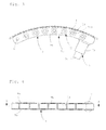
Fig. 4 is a plan view showing a state where rollers are removed from the chain guide ofFig. 1 . -
Fig. 5 is a sectional view taken in line A-A inFig. 4 . -
Fig. 6 is a partially enlarged view ofFig. 5 . -
Fig. 7 is a transverse sectional view showing an embodiment of a chain guide according to the present invention. -
Fig. 8 is a transverse sectional view showing an embodiment of the chain guide according to the present invention. -
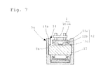
Fig. 9 is a transverse sectional view showing another embodiment of the chain guide according to the present invention. -
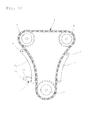
Fig. 10 is a front view showing an example of a chain tensioner device using the chain guide according to the present invention. - Embodiments according to the present invention will be described in detail with reference to the accompanying drawings. Note that components, which are the same or equivalent to each other, are denoted by the same reference numeral or character in the drawings, and the description thereof is not repeated to avoid duplication of description.
- A chain guide according to an embodiment of the present invention is used, for example, for giving tension to a timing chain of an engine valve drive system.
- As shown in
Fig. 10 , atiming chain 1 is endlessly wound around acrank sprocket 2 attached to a crankshaft, afirst cam sprocket 3 attached to a first cam shaft of a valve train, and asecond cam sprocket 4 attached to a second cam shaft. - A
first chain guide 5a and asecond chain guide 5b are respectively arranged on thetiming chain 1 between thecrank sprocket 2 and thefirst cam sprocket 3, and on thetiming chain 1 between thecrank sprocket 2 and thesecond cam sprocket 4 so as to prevent thetiming chain 1 from being slackened. - The
first chain guide 5a is configured such that one longitudinal end side thereof is supported by arotary shaft 6 so as to be rotatable with respect to an engine, and such that the other longitudinal end side thereof is rocked by atensioner plunger 7 so as to give tension to thetiming chain 1. - The
second chain guide 5b, whose opposite longitudinal ends are fixed by mountingshafts 8 with respect to the engine, guides thetensioned timing chain 1 so that thetiming chain 1 is not slackened. - The
first chain guide 5a and thesecond chain guide 5b are different from each other only in that, while thefirst chain guide 5a is rocked by thetensioner plunger 7 with respect to the engine, thesecond chain guide 5b is not rocked and fixed with respect to the engine, and hence have the same basic structure for guiding thetiming chain 1. Note that thechain guides - The
chain guide 5a is configured such that atensioner plunger 7 is integrally attached to aguide base 9 formed in a curved shape along thetiming chain 1. - As shown in
Fig. 5 , thetensioner plunger 7 includes acylinder chamber 7a, apiston 7b which is provided slidably in thecylinder chamber 7a, and a return spring 7c which is inserted into thepiston 7b and which presses thepiston 7b in the outer direction. - The
cylinder chamber 7a is provided therein with apressure chamber 7d which is located on the depth side of thepiston 7b, anoil supply passage 7e which supplies a hydraulic fluid to thepressure chamber 7d, and a check valve 7f which prevents reverse flow of the hydraulic fluid. - As a method for fixing the tensioner plunger 7 to the
chain guide base 9, it is possible to adopt a bonding method, a screw connection method, and the like, in addition to a method in which an annularfixing step section 10 configured to be fitted to thecylinder chamber 7a is provided on the bottom surface of theguide base 9, and in which thecylinder chamber 7a is press-fitted into thefixing step section 10. - When the
guide base 9 is formed, thecylinder chamber 7a may be attached to theguide base 9 by insertion molding. - The
chain guide base 9 is composed of a pair ofside plate members 9a, andpillar members 9b connecting theside plate members 9a. - Through
holes 11 are respectively provided at opposite longitudinal ends of each of theside plate members 9a. A shaft (not shown) is inserted into the throughhole 11, so as to be fixed to, for example, an inner wall of an engine cover. - One longitudinal end side of the
first chain guide 5a is supported by therotary shaft 6 so as to be rotatable with respect to the engine, and the other longitudinal end side thereof is rocked by thetensioner plunger 7 to adjust tension of thetiming chain 1. - The pair of
side plate members 9a have a predetermined interval therebetween in the width direction, and the plurality ofrollers 12 which are brought into contact with thetiming chain 1 are arrayed between theside plate members 9a. Therollers 12 may be arrayed at a uniform pitch along theside plate member 9a having a curved shape, or the pitches between therollers 12 may be changed so that more of therollers 12 are arranged on the entrance side in the running direction of thetiming chain 1. - Support recesses 14, which support opposite ends of a
support shaft 13 of theroller 12, are respectively provided in the mutually facing wall surfaces of theside plate members 9a. - As shown in
Fig. 4 ,Fig. 5 and Fig. 6 , each of the support recesses 14 is composed of aninsertion recess 14a having an opening in the side-plate-member end surface on the side of thetiming chain 1, and a fixingrecess 14b connected to theinsertion recess 14a and having a circular arc shape into which the end portion of thesupport shaft 13 is fitted. Each of opposite ends of thesupport shaft 13 of theroller 12 is inserted from theinsertion recess 14a into the fixingrecess 14b, so as to be supported by each of theside plate members 9a. - As shown in
Fig. 5 , a plurality of the support recesses 14 are arrayed along the curved shape of theside plate member 9a, and thepillar member 9b is arranged between the support recesses 14. - As shown in the enlarged view of
Fig. 6 , theinsertion recess 14a has a wide opening section a and is formed in a tapered shape, the width of which is gradually reduced from the opening section a to the position of the fixingrecess 14b. Further, the width dimension of an insertion port b, located at the position at which theinsertion recess 14a is connected to the fixingrecess 14b, is smaller than the diameter φ of the fixingrecess 14b having the circular arc shape. - The fixing
recess 14b having the circular arc shape is formed to have the diameter φ smaller than the diameter of thesupport shaft 13 so that thesupport shaft 13 is press-fitted into the fixingrecess 14b. - Further, as shown in
Fig. 1 and Fig. 2 , thesupport recess 14 is formed in theside plate member 9a in a non-penetrating state. Thereby, the shaft direction movement of thesupport shaft 13 inserted into thesupport recess 14 is regulated. - In the present embodiment, the
side plate member 9a and thepillar member 9b are formed integrally by resin molding using, for example, polyamide (PA) 46 or polyamide (PA) 66 which are polymers obtained by polycondensation of diaminobutane and adipic acid. Further, it is possible to use a material obtained by combining glass fiber or carbon fiber with PA46 or PA66 in order to increase the mechanical strength. - When the
side plate member 9a and thepillar member 9b are formed of resin, the weight of theguide base 9 can be reduced. Further, as the resin which forms theside plate member 9a and thepillar member 9b, resin having high heat conductivity can also be used for dissipating the frictional heat. - Note that, other than resin, the
side plate member 9a and thepillar member 9b can also be formed, for example, by casting using a light metal, such as aluminum and magnesium. In this case, it is desirable that theside plate member 9a and thepillar member 9b are integrated with a tensioner plan jack. - The
roller 12 may be composed of thesupport shaft 13 and a roller bearing having a steelouter ring 12a as shown inFig. 7 , or may also be configured such that, as shown inFig. 8 , an ironouter ring 12d which is brought into contact with thetiming chain 1 is arranged to cover the outer peripheral surface of the steelouter ring 12a. - The roller bearing is a radial roller bearing composed of the steel
outer ring 12a having inward-extending flange sections at opposite ends thereof, and aroller 12c provided with aretainer 12b and incorporated in the steelouter ring 12a. - The
outer ring 12a can be formed by press-forming or cut-forming. - When the
outer ring 12a is formed by press forming, it is preferred that, after theretainer 12b and theroller 12c are incorporated into theouter ring 12a, the inward-extending flange sections are respectively formed at opposite ends of theouter ring 12a by edge bending processing, and that theouter ring 12a is then heat treated after the assembly. - Further, when the hardness of the
outer ring 12a or the ironouter ring 12d is set higher than the hardness of thetiming chain 1, the wear of theouter ring 12a or the ironouter ring 12d can be prevented. - As a material of the
outer ring 12a or the ironouter ring 12d, a material, such as SUJ2 and SCM, which can be subjected to hardening treatment by heat treatment, is used. - In order to improve the retaining performance of lubricating oil, minute depressions and projections may be formed on the surface of the
outer ring 12a or the ironouter ring 12d. - Further, the surface of the
outer ring 12a or the ironouter ring 12d may be subjected to nitriding treatment. - In order to reduce contact resistance with the
timing chain 1, it is desirable that the surface of theouter ring 12a or the ironouter ring 12d has a generating line shape of a barrel shape or a straight shape. - In order to reduce vibration and to achieve silence, it is desirable that the roundness of the
outer ring 12a or the ironouter ring 12d is 20 µm or less. - Further, from a viewpoint of mechanical strength, it is preferred that the thickness of the
outer ring 12a or the ironouter ring 12d is 1 mm or more. - The
rollers 12c are held by theretainers 12b in the circumferential direction at predetermined intervals therebetween. As theretainer 12b, a V-shaped retainer having a V-shaped pillar section is used. When theretainer 12b is used, it is possible to prevent the skewing of theroller 12c and to prevent the end surface of theroller 12c from being brought into direct contact with the flange section of theouter ring 12a. Further, it is possible to prevent the wear of theside plate member 9a. Note that the roller bearing having a roller structure without using theretainer 12b may also be adopted. - Next, in order to attach the
roller 12 to theside plate members 9a facing each other, theroller 12 into which thesupport shaft 13 is fitted is first prepared as shown inFig. 5 . Further, each of opposite ends of thesupport shaft 13 of theroller 12 is arranged to face theinsertion recess 14a of the support recess formed in each of the mutually facing wall surfaces of theside plate members 9a, and is then dropped into theinsertion recess 14a, so as to be inserted into the fixingrecess 14b from theinsertion recess 14a. In the present embodiment, the opening section a is formed to be wide, and theinsertion recess 14a is formed to have a tapered shape. Therefore, when thesupport shaft 13 is inserted, thesupport shaft 13 can be easily guided from the opening section a to the circular arc-shapedfixing recess 14b through the insertion port b. - In the above-described embodiment, the diameter φ of the circular arc-shaped
fixing recess 14b is formed to be smaller than the diameter of thesupport shaft 13, and hence thesupport shaft 13 is press-fitted and attached to the fixingrecess 14b. As a result, it is possible to suppress the rotation of thesupport shaft 13. In addition, the width of the insertion port b connected to the fixingrecess 14b is formed to be smaller than the diameter φ of the circular arc-shapedfixing recess 14b, and hence the insertion port b performs a function of preventing the coming-off of thesupport shaft 13. Further, thesupport recess 14 is formed so as not to penetrate theside plate member 9a, and hence thesupport shaft 13 inserted into thesupport recess 14 can be prevented from moving in the shaft direction. - In the state where the
support shafts 13 of theroller 12 are respectively fitted into the support recesses 14 of the mutually facingside plate members 9a, the outer periphery surface of theroller 12 is lower than the end surface of theside plate member 9a as shown inFig. 1 ,Fig. 3 ,Fig. 4 ,Fig 7 andFig. 8 . Thereby, thetiming chain 1 is guided between the mutually facing wall surfaces of theside plate members 9a while being brought into contact with the ironouter ring 12d, so that the runningtiming chain 1 is prevented from coming off from the mutually facing wall surfaces of theside plate members 9a. - Further, it is desirable that each height of the end surface of the
side plate member 9a and theroller 12 is lower than the position of a connection pin 1b mutually connecting plates 1a constituting thetiming chain 1 as shown inFig. 7 orFig. 8 . When each height of the end surface of theside plate member 9a and theroller 12 is higher than the position of the connection pin 1b mutually connecting the plates 1a constituting thetiming chain 1, the connection pin 1b is brought into contact with the mutually facing wall surfaces of theside plate members 9a, and hence such configuration is not preferred. - Next,
Fig. 9 is a transverse sectional view showing achain guide 5a according to another embodiment of the present invention. In this embodiment, components common to those of the above-described embodiments are denoted by the same reference numerals and reference characters, and the description thereof is omitted, and only different portions are described. In this embodiment, as shown inFig. 9 , anoil hole 15 is provided at the center portion of thesupport shaft 13, and adischarge hole 15a for discharging oil is provided at a position opposite to thetiming chain 1. Further, ahole 16 connected to theoil hole 15 is provided in theside plate member 9a. When theoil hole 15 is provided in this way, it is possible to supply oil to the inside of the bearing. Further, it is also possible to dissipate heat. It is preferred that thedischarge hole 15a of theoil hole 15 is formed in the direction opposite to thetiming chain 1 as described above. Thereby, oil is smoothly supplied to the inside of the bearing. Further, when theoil hole 15 is provided, thesupport shaft 13 is formed in a hollow shape, so that the weight of the chain guide 5 is reduced. - Further, in addition to the engine timing chain, the
chain guide 5a according to each of the embodiments of the present invention can give tension to various driving chains, and can also reduce mechanical loss. - Further, as shown in
Fig. 10 , a chain tensioner device using thechain guide 5a according to the present invention is composed of thefirst chain guide 5a having one end provided with the throughhole 11 into which therotary shaft 6 is inserted, and having the other end side which is rocked by thetensioner plunger 7, and thesecond chain guide 5b having opposite ends which are respectively fixed by the mountingshafts 8 with respect to the engine. With the chain tensioner device, the mechanical loss and weight of the engine timing chain are reduced, so that the fuel consumption rate can be improved. - Note that the
timing chain 1 can be used for any of a roller chain and a silent chain. - Further, in the above embodiments, an example is shown in which the
side plate member 9a and thepillar member 9b are formed integrally with each other, but each of theside plate member 9a and thepillar member 9b may be formed as a separated body. - Further, in the above embodiments, an example is shown, in which a chain guide composed of arraying a plurality of rollers is used, but a chain guide, in which no roller is used, may be integrally attached to a tensioner plunger as described in the prior art of
Patent Literature 1. - Further, in the above embodiments, a hydraulic tensioner plunger is described, but a mechanical tensioner plunger using a screw or a spring may also be integrally attached to the chain guide.
- The chain guide according to the present invention is effectively used in a mechanism which gives tension to a driving chain of an engine, and the like.
-
- 1
- Timing chain
- 2
- Crank sprocket
- 3
- First cam sprocket
- 4
- Second cam sprocket
- 5a
- First chain guide
- 5b
- Second chain guide
- 6
- Rotary shaft
- 7
- Tensioner plunger
- 7a
- Cylinder chamber
- 7b
- Piston
- 7c
- Return spring
- 7d
- Pressure chamber
- 7e
- Oil supply passage
- 7f
- Check valve
- 8
- Mounting shaft
- 9
- Chain guide base
- 9a
- Side plate member
- 9b
- Pillar member
- 10
- Fixing step section
- 11
- Through hole
- 12
- Roller
- 12a
- Outer ring
- 12b
- Retainer
- 12c
- Roller
- 12d
- Iron outer ring
- 13
- Support shaft
- 14
- Support recess
- 14a
- Insertion recess
- 14b
- Fixing recess
- 15
- Oil hole
- 15a
- Discharge hole
- 16
- Hole
Claims (15)
- A chain guide comprising a chain guide base provided along the running direction of a chain, wherein a tensioner plunger which presses the chain guide base against the chain side is integrally attached to the chain guide base.
- The chain guide according to claim 1, wherein a plurality of rollers, which are brought into contact with the endlessly connected chain, are arranged in the chain guide base.
- The chain guide according to claim 1 or claim 2, wherein the roller is composed of a support shaft, opposite ends of which are supported by the chain guide base, and a roller bearing which includes an outer ring provided on the outer peripheral surface of the support shaft.
- The chain guide according to claim 3, wherein the outer periphery of the outer ring is covered by an iron outer ring which is brought into contact with the chain.
- The chain guide according to claim 3 or claim 4, wherein the roller bearing is composed of a steel outer ring having inward-extending flange sections at opposite ends thereof, and a roller provided with a retainer and incorporated in the outer ring.
- The chain guide according to any of claim 3 to claim 5, wherein the steel outer ring is formed by press-forming.
- The chain guide according to any of claim 3 to claim 5, wherein the steel outer ring is formed by cut-forming.
- The chain guide according to any of claim 3 to claim 7, wherein the hardness of the outer ring or the hardness of the iron outer ring is higher than the hardness of the chain.
- The chain guide according to any of claim 3 to claim 8, wherein the outer ring or the iron outer ring has a generating line shape of a barrel shape or a straight shape.
- The chain guide according to any of claim 3 to claim 9, wherein minute depressions and projections are formed on the surface of the outer ring or the iron outer ring in order to improve the retaining performance of lubricating oil.
- The chain guide according to any of claim 3 to claim 10, wherein the outer ring or the iron outer ring has a thickness of 1 mm or more.
- The chain guide according to any of claim 3 to claim 11, wherein the surface of the outer ring or the iron outer ring is subjected to hardening treatment.
- The chain guide according to claim 12, wherein the hardening treatment of the surface of the outer ring or the iron outer rings is nitriding treatment.
- The chain guide according to any of claim 3 to claim 13, wherein the roundness of the outer ring or the iron outer ring is 20 µm or less.
- A chain tensioner device wherein the chain guide according to any of claim 1 to claim 14 is arranged at a middle portion of an endlessly connected chain.
Applications Claiming Priority (2)
| Application Number | Priority Date | Filing Date | Title |
|---|---|---|---|
| JP2011037510A JP2012172810A (en) | 2011-02-23 | 2011-02-23 | Chain guide and chain tensioner device |
| PCT/JP2012/052452 WO2012114846A1 (en) | 2011-02-23 | 2012-02-03 | Chain guide and chain tensioner device |
Publications (2)
| Publication Number | Publication Date |
|---|---|
| EP2679862A1 true EP2679862A1 (en) | 2014-01-01 |
| EP2679862A4 EP2679862A4 (en) | 2015-08-05 |
Family
ID=46720634
Family Applications (1)
| Application Number | Title | Priority Date | Filing Date |
|---|---|---|---|
| EP12750030.4A Withdrawn EP2679862A4 (en) | 2011-02-23 | 2012-02-03 | Chain guide and chain tensioner device |
Country Status (5)
| Country | Link |
|---|---|
| US (1) | US20130324339A1 (en) |
| EP (1) | EP2679862A4 (en) |
| JP (1) | JP2012172810A (en) |
| CN (1) | CN103384783B (en) |
| WO (1) | WO2012114846A1 (en) |
Cited By (1)
| Publication number | Priority date | Publication date | Assignee | Title |
|---|---|---|---|---|
| DE102014211516A1 (en) | 2014-06-17 | 2016-01-14 | Schaeffler Technologies AG & Co. KG | Zugmittelspanner with on the traction means unrollable pressure piece and spring-damper unit |
Families Citing this family (9)
| Publication number | Priority date | Publication date | Assignee | Title |
|---|---|---|---|---|
| CN103384784B (en) * | 2011-02-23 | 2016-11-16 | Ntn株式会社 | Chain guide and chain stretching device |
| US9562593B2 (en) * | 2011-06-13 | 2017-02-07 | Ntn Corporation | Chain guide and chain drive apparatus |
| JP5706261B2 (en) * | 2011-07-25 | 2015-04-22 | Ntn株式会社 | Chain transmission for camshaft drive |
| WO2013136956A1 (en) * | 2012-03-12 | 2013-09-19 | Ntn株式会社 | Chain guide and chain drive device |
| EP2857718B1 (en) * | 2012-05-24 | 2017-01-04 | NTN Corporation | Chain guide and chain transmission device |
| JP5966742B2 (en) | 2012-08-03 | 2016-08-10 | スズキ株式会社 | Manual transmission shift device |
| JP6205291B2 (en) * | 2014-02-17 | 2017-09-27 | Ntn株式会社 | Chain drive for camshaft drive |
| JP6265810B2 (en) * | 2014-03-27 | 2018-01-24 | Ntn株式会社 | Chain guide and chain transmission |
| US9669702B2 (en) * | 2015-11-04 | 2017-06-06 | Jaime Lozano | Fuel saving system |
Family Cites Families (16)
| Publication number | Priority date | Publication date | Assignee | Title |
|---|---|---|---|---|
| JPH043150U (en) * | 1990-04-23 | 1992-01-13 | ||
| DE19500940C1 (en) * | 1995-01-14 | 1996-07-11 | Bosch Gmbh Robert | Tightener for chains, esp. control chains of IC engines |
| JP2895786B2 (en) * | 1995-11-10 | 1999-05-24 | 株式会社椿本チエイン | Transmission chain tensioner device |
| JPH09236157A (en) | 1996-02-29 | 1997-09-09 | Suzuki Motor Corp | Engine chain tensioner device |
| JPH1163173A (en) * | 1997-08-22 | 1999-03-05 | Koyo Seiko Co Ltd | Pulley |
| JP3717645B2 (en) * | 1997-10-31 | 2005-11-16 | Ntn株式会社 | Idler pulley |
| JP2000266141A (en) * | 1999-03-16 | 2000-09-26 | Suzuki Motor Corp | Chain tensioner |
| JP2001187948A (en) * | 1999-12-28 | 2001-07-10 | Unitta Co Ltd | Drive transmission device |
| JP2003269555A (en) * | 2002-03-19 | 2003-09-25 | Tsubakimoto Chain Co | Wear-resistant tensioner |
| US6945889B2 (en) * | 2002-10-04 | 2005-09-20 | Borgwarner Inc. | Hydraulic chain tensioner |
| JP4327209B2 (en) * | 2007-03-06 | 2009-09-09 | 株式会社椿本チエイン | Hydraulic tensioner that can be installed |
| JP4357549B2 (en) * | 2007-06-19 | 2009-11-04 | 株式会社椿本チエイン | Hydraulic tensioner that can be installed |
| JP2009092132A (en) * | 2007-10-09 | 2009-04-30 | Ntn Corp | Chain tensioner |
| EP2395261B1 (en) * | 2009-02-03 | 2015-10-21 | NTN Corporation | Chain guide and chain tensioner device |
| JP5081843B2 (en) | 2009-02-03 | 2012-11-28 | Ntn株式会社 | Chain guide and chain tensioner device |
| US20110029461A1 (en) * | 2009-07-31 | 2011-02-03 | Invensys Systems Inc. | Dynamic Electrical Power Pricing Communication Architecture |
-
2011
- 2011-02-23 JP JP2011037510A patent/JP2012172810A/en active Pending
-
2012
- 2012-02-03 WO PCT/JP2012/052452 patent/WO2012114846A1/en not_active Ceased
- 2012-02-03 US US14/000,317 patent/US20130324339A1/en not_active Abandoned
- 2012-02-03 EP EP12750030.4A patent/EP2679862A4/en not_active Withdrawn
- 2012-02-03 CN CN201280009973.0A patent/CN103384783B/en not_active Expired - Fee Related
Cited By (1)
| Publication number | Priority date | Publication date | Assignee | Title |
|---|---|---|---|---|
| DE102014211516A1 (en) | 2014-06-17 | 2016-01-14 | Schaeffler Technologies AG & Co. KG | Zugmittelspanner with on the traction means unrollable pressure piece and spring-damper unit |
Also Published As
| Publication number | Publication date |
|---|---|
| US20130324339A1 (en) | 2013-12-05 |
| EP2679862A4 (en) | 2015-08-05 |
| CN103384783B (en) | 2016-08-10 |
| CN103384783A (en) | 2013-11-06 |
| JP2012172810A (en) | 2012-09-10 |
| WO2012114846A1 (en) | 2012-08-30 |
Similar Documents
| Publication | Publication Date | Title |
|---|---|---|
| US9429216B2 (en) | Chain guide and chain tensioner device | |
| US20130324339A1 (en) | Chain guide and chain tensioner device | |
| US9115787B2 (en) | Chain guide and chain tensioner device | |
| JP2011047473A (en) | Chain guide and chain tensioner device | |
| EP2679864B1 (en) | Timing chain drive device | |
| JP2011058551A (en) | Chain guide and chain tensioner device | |
| US9562593B2 (en) | Chain guide and chain drive apparatus | |
| JP2012172808A (en) | Chain guide and chain tensioner device | |
| JP5676305B2 (en) | Chain guide and chain tensioner device | |
| EP2738422A1 (en) | Chain guide and chain drive device | |
| JP2014139482A (en) | Chain guide | |
| JP5662198B2 (en) | Chain guide and chain tensioner device | |
| JP2012189200A (en) | Chain guide and chain tensioner device | |
| JP5868617B2 (en) | Chain guide and chain tensioner device | |
| JP2012177390A (en) | Chain tensioner device | |
| WO2013011916A1 (en) | Chain guide and chain driving gear | |
| CN104136809A (en) | Chain guide and chain transmission device | |
| JP2013002468A (en) | Chain guide and chain tensioner device | |
| JP2012189201A (en) | Chain guide and chain tensioner device | |
| JP2012177391A (en) | Chain guide and chain tensioner device | |
| JP2012172807A (en) | Chain guide and chain tensioner device | |
| JP5706260B2 (en) | Chain guide and chain transmission | |
| WO2012114845A1 (en) | Chain guide and chain tensioner device | |
| JP2012172809A (en) | Chain guide and chain tensioner device |
Legal Events
| Date | Code | Title | Description |
|---|---|---|---|
| PUAI | Public reference made under article 153(3) epc to a published international application that has entered the european phase |
Free format text: ORIGINAL CODE: 0009012 |
|
| 17P | Request for examination filed |
Effective date: 20130822 |
|
| AK | Designated contracting states |
Kind code of ref document: A1 Designated state(s): AL AT BE BG CH CY CZ DE DK EE ES FI FR GB GR HR HU IE IS IT LI LT LU LV MC MK MT NL NO PL PT RO RS SE SI SK SM TR |
|
| DAX | Request for extension of the european patent (deleted) | ||
| RA4 | Supplementary search report drawn up and despatched (corrected) |
Effective date: 20150703 |
|
| RIC1 | Information provided on ipc code assigned before grant |
Ipc: F16H 7/08 20060101AFI20150629BHEP |
|
| 17Q | First examination report despatched |
Effective date: 20170306 |
|
| STAA | Information on the status of an ep patent application or granted ep patent |
Free format text: STATUS: THE APPLICATION IS DEEMED TO BE WITHDRAWN |
|
| 18D | Application deemed to be withdrawn |
Effective date: 20190618 |