EP2679772B1 - Surface portante - Google Patents
Surface portante Download PDFInfo
- Publication number
- EP2679772B1 EP2679772B1 EP13172933.7A EP13172933A EP2679772B1 EP 2679772 B1 EP2679772 B1 EP 2679772B1 EP 13172933 A EP13172933 A EP 13172933A EP 2679772 B1 EP2679772 B1 EP 2679772B1
- Authority
- EP
- European Patent Office
- Prior art keywords
- stagnation
- trench
- airfoil
- exterior surface
- pressure side
- Prior art date
- Legal status (The legal status is an assumption and is not a legal conclusion. Google has not performed a legal analysis and makes no representation as to the accuracy of the status listed.)
- Active
Links
- 238000001816 cooling Methods 0.000 claims description 51
- 239000012530 fluid Substances 0.000 claims description 31
- 238000004891 communication Methods 0.000 claims description 10
- 230000003247 decreasing effect Effects 0.000 claims 2
- 239000000567 combustion gas Substances 0.000 description 9
- 238000002485 combustion reaction Methods 0.000 description 8
- 239000000446 fuel Substances 0.000 description 7
- 239000007789 gas Substances 0.000 description 6
- 230000007704 transition Effects 0.000 description 3
- ATUOYWHBWRKTHZ-UHFFFAOYSA-N Propane Chemical compound CCC ATUOYWHBWRKTHZ-UHFFFAOYSA-N 0.000 description 2
- 239000003570 air Substances 0.000 description 2
- 239000003949 liquefied natural gas Substances 0.000 description 2
- VNWKTOKETHGBQD-UHFFFAOYSA-N methane Chemical compound C VNWKTOKETHGBQD-UHFFFAOYSA-N 0.000 description 2
- 238000000034 method Methods 0.000 description 2
- 238000012986 modification Methods 0.000 description 2
- 230000004048 modification Effects 0.000 description 2
- 238000011144 upstream manufacturing Methods 0.000 description 2
- 229910000851 Alloy steel Inorganic materials 0.000 description 1
- 239000012080 ambient air Substances 0.000 description 1
- 230000004323 axial length Effects 0.000 description 1
- 229910010293 ceramic material Inorganic materials 0.000 description 1
- 239000000571 coke Substances 0.000 description 1
- 230000005611 electricity Effects 0.000 description 1
- 239000001257 hydrogen Substances 0.000 description 1
- 229910052739 hydrogen Inorganic materials 0.000 description 1
- 125000004435 hydrogen atom Chemical class [H]* 0.000 description 1
- 239000000203 mixture Substances 0.000 description 1
- 239000003345 natural gas Substances 0.000 description 1
- 230000037361 pathway Effects 0.000 description 1
- 238000010248 power generation Methods 0.000 description 1
- 230000008569 process Effects 0.000 description 1
- 239000001294 propane Substances 0.000 description 1
- -1 steam Substances 0.000 description 1
Images


Classifications
-
- F—MECHANICAL ENGINEERING; LIGHTING; HEATING; WEAPONS; BLASTING
- F01—MACHINES OR ENGINES IN GENERAL; ENGINE PLANTS IN GENERAL; STEAM ENGINES
- F01D—NON-POSITIVE DISPLACEMENT MACHINES OR ENGINES, e.g. STEAM TURBINES
- F01D5/00—Blades; Blade-carrying members; Heating, heat-insulating, cooling or antivibration means on the blades or the members
- F01D5/12—Blades
- F01D5/14—Form or construction
- F01D5/18—Hollow blades, i.e. blades with cooling or heating channels or cavities; Heating, heat-insulating or cooling means on blades
- F01D5/186—Film cooling
-
- F—MECHANICAL ENGINEERING; LIGHTING; HEATING; WEAPONS; BLASTING
- F01—MACHINES OR ENGINES IN GENERAL; ENGINE PLANTS IN GENERAL; STEAM ENGINES
- F01D—NON-POSITIVE DISPLACEMENT MACHINES OR ENGINES, e.g. STEAM TURBINES
- F01D5/00—Blades; Blade-carrying members; Heating, heat-insulating, cooling or antivibration means on the blades or the members
- F01D5/12—Blades
- F01D5/14—Form or construction
- F01D5/18—Hollow blades, i.e. blades with cooling or heating channels or cavities; Heating, heat-insulating or cooling means on blades
- F01D5/187—Convection cooling
-
- F—MECHANICAL ENGINEERING; LIGHTING; HEATING; WEAPONS; BLASTING
- F05—INDEXING SCHEMES RELATING TO ENGINES OR PUMPS IN VARIOUS SUBCLASSES OF CLASSES F01-F04
- F05D—INDEXING SCHEME FOR ASPECTS RELATING TO NON-POSITIVE-DISPLACEMENT MACHINES OR ENGINES, GAS-TURBINES OR JET-PROPULSION PLANTS
- F05D2240/00—Components
- F05D2240/20—Rotors
- F05D2240/30—Characteristics of rotor blades, i.e. of any element transforming dynamic fluid energy to or from rotational energy and being attached to a rotor
- F05D2240/305—Characteristics of rotor blades, i.e. of any element transforming dynamic fluid energy to or from rotational energy and being attached to a rotor related to the pressure side of a rotor blade
-
- F—MECHANICAL ENGINEERING; LIGHTING; HEATING; WEAPONS; BLASTING
- F05—INDEXING SCHEMES RELATING TO ENGINES OR PUMPS IN VARIOUS SUBCLASSES OF CLASSES F01-F04
- F05D—INDEXING SCHEME FOR ASPECTS RELATING TO NON-POSITIVE-DISPLACEMENT MACHINES OR ENGINES, GAS-TURBINES OR JET-PROPULSION PLANTS
- F05D2240/00—Components
- F05D2240/20—Rotors
- F05D2240/30—Characteristics of rotor blades, i.e. of any element transforming dynamic fluid energy to or from rotational energy and being attached to a rotor
- F05D2240/306—Characteristics of rotor blades, i.e. of any element transforming dynamic fluid energy to or from rotational energy and being attached to a rotor related to the suction side of a rotor blade
-
- F—MECHANICAL ENGINEERING; LIGHTING; HEATING; WEAPONS; BLASTING
- F05—INDEXING SCHEMES RELATING TO ENGINES OR PUMPS IN VARIOUS SUBCLASSES OF CLASSES F01-F04
- F05D—INDEXING SCHEME FOR ASPECTS RELATING TO NON-POSITIVE-DISPLACEMENT MACHINES OR ENGINES, GAS-TURBINES OR JET-PROPULSION PLANTS
- F05D2260/00—Function
- F05D2260/20—Heat transfer, e.g. cooling
- F05D2260/202—Heat transfer, e.g. cooling by film cooling
-
- F—MECHANICAL ENGINEERING; LIGHTING; HEATING; WEAPONS; BLASTING
- F05—INDEXING SCHEMES RELATING TO ENGINES OR PUMPS IN VARIOUS SUBCLASSES OF CLASSES F01-F04
- F05D—INDEXING SCHEME FOR ASPECTS RELATING TO NON-POSITIVE-DISPLACEMENT MACHINES OR ENGINES, GAS-TURBINES OR JET-PROPULSION PLANTS
- F05D2260/00—Function
- F05D2260/20—Heat transfer, e.g. cooling
- F05D2260/204—Heat transfer, e.g. cooling by the use of microcircuits
Definitions
- the present invention generally involves an airfoil, such as might be used in a turbine.
- Turbines are widely used in a variety of aviation, industrial, and power generation applications to perform work.
- Each turbine generally includes alternating stages of circumferentially mounted stator vanes and rotating blades.
- Each stator vane and rotating blade may include high alloy steel and/or ceramic material shaped into an airfoil.
- a compressed working fluid such as steam, combustion gases, or air, flows across the stator vanes and rotating blades along a gas path in the turbine.
- the stator vanes accelerate and direct the compressed working fluid onto the subsequent stage of rotating blades to impart motion to the rotating blades and perform work.
- One aspect of the present invention is an airfoil that includes an interior surface, an exterior surface opposed to the interior surface, a pressure side, a suction side opposed to the pressure side, a stagnation line between the pressure and suction sides, and a trailing edge between the pressure and suction sides and downstream from the stagnation line.
- a first column of overlapping stagnation trench segments is on the exterior surface, and the stagnation line passes through at least a portion of each of the overlapping stagnation trench segments. At least one cooling passage in each stagnation trench segment provides fluid communication from the interior surface to the exterior surface.
- Another aspect of the present invention is an airfoil that includes an interior surface, an exterior surface opposed to the interior surface, a pressure side, a suction side opposed to the pressure side, a stagnation line between the pressure and suction sides, and a trailing edge between the pressure and suction sides and downstream from the stagnation line.
- a second column of overlapping pressure side trench segments is on the pressure side
- a third column of overlapping suction side trench segments is on the suction side.
- Each pressure side trench segment and each suction side trench segment has a first end and a second end downstream and radially outward from the first end.
- At least one side cooling passage is in each pressure side trench segment and in each suction side trench segment, and the side cooling passages provide fluid communication from the interior surface to the exterior surface.
- an airfoil in yet another aspect, includes an interior surface, an exterior surface opposed to the interior surface, a pressure side, a suction side opposed to the pressure side, a stagnation line between the pressure and suction sides, and a trailing edge between the pressure and suction sides and downstream from the stagnation line.
- a first column of overlapping stagnation trench segments is on the exterior surface, and the stagnation line passes through at least a portion of each of the overlapping stagnation trench segments.
- At least one cooling passage is in each stagnation trench segment and provides fluid communication from the interior surface to the exterior surface.
- a second column of overlapping pressure side trench segments is on the pressure side, and a third column of overlapping suction side trench segments is on the suction side.
- At least one side cooling passage is in each pressure side trench segment and in each suction side trench segment to provide fluid communication from the interior surface to the exterior surface.
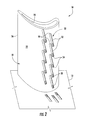
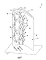
- Fig. 1 provides a perspective view of an airfoil 10 according to one embodiment of the present invention
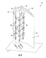
- Fig. 2 provides a perspective view of the suction side of the airfoil shown in Fig. 1
- the airfoil 10 may be used, for example, as a rotating blade or stationary vane in a turbine to convert kinetic energy associated with a compressed working fluid into mechanical energy.
- the compressed working fluid may be steam, combustion gases, air, or any other fluid having kinetic energy.
- the airfoil 10 is generally connected to a platform or sidewall 12.
- the platform or sidewall 12 generally serves as the radial boundary for a gas path inside the turbine and provides an attachment point for the airfoil 10.
- the airfoil 10 may include an interior surface 16 and an exterior surface 18 opposed to the interior surface 16 and connected to the platform 12.
- the exterior surface generally includes a pressure side 20 and a suction side 22 opposed to the pressure side 20.
- the pressure side 20 is generally concave
- the suction side 22 is generally convex to provide an aerodynamic surface over which the compressed working fluid flows.
- a stagnation line 24 at a leading edge of the airfoil 10 between the pressure and suction sides 20, 22 represents the dividing line between fluid flow across the pressure side 20 and fluid flow across the suction side 22 of the airfoil 10.
- the stagnation line 24 often has the highest temperature over the exterior surface 18 of the airfoil 10.
- a trailing edge 26 is between the pressure and suction sides 20, 22 and downstream from the stagnation line 24. In this manner, the exterior surface 18 creates an aerodynamic surface suitable for converting the kinetic energy associated with the compressed working fluid into mechanical energy.
- the exterior surface 18 generally includes a radial length 30 that extends from the platform 12 radially outward and an axial length 32 that extends from the stagnation line 24 to the trailing edge 26.
- One or more columns of trench segments may extend radially and/or axially in the exterior surface 18, and each trench segment may include at least one cooling passage that provides fluid communication from the interior surface 16 to the exterior surface 18. In this manner, cooling media may be supplied inside the airfoil 10, and the cooling passages allow the cooling media to flow through the airfoil 10 to provide film cooling to the exterior surface 18.
- the trench segments may be located anywhere on the airfoil 10 and/or platform or sidewall 12, may be straight or arcuate, and may be aligned or staggered with respect to one another.
- the trench segments may have varying lengths, widths, and/or depths.
- the varying lengths, widths, and/or depths of the trench segments alter the distribution of the cooling media across the exterior surface 18. For example, widening the trench segments and making them shallower as they move away from the cooling passages may assist in diffusing the cooling media across the exterior surface 18.
- overlapping stagnation trench segments 40 may be arranged in a first column 42 on the exterior surface 18 so that the stagnation line 24 passes through at least a portion of each of the stagnation trench segments 40.
- Each stagnation trench segment 40 may be substantially straight and canted at an angle with respect to the immediately adjacent stagnation trench segment 40 so that the stagnation trench segments 40 overlap one another radially along the exterior surface 18.
- overlap means that moving radially outward from the platform 12, the end of one trench segment 40 is radially outward of the beginning of the next trench segment 40 in the same column.
- At least one cooling passage 44 in each stagnation trench segment 40 may provide fluid communication from the interior surface 16 to the exterior surface 18. In this manner, the cooling passages 44 may provide substantially continuous film cooling through the stagnation trench segments 40 along the stagnation line 24.
- Additional overlapping trench segments may be arranged on the pressure and/or suction sides 20, 22 of the exterior surface 18.
- overlapping pressure side trench segments 46 may be arranged in a second column 48 on the pressure side 20 of the exterior surface 18.
- overlapping suction side trench segments 50 may be arranged in a third column 52 on the suction side 22 of the exterior surface 18, as shown in Fig. 2 .
- Each pressure side trench segment 46 and each suction side trench segment 50 may be canted or angled in the opposite direction. For example, as shown in Figs.
- each pressure side trench segment 46 and/or each suction side trench segment 50 may have a first end 54 and a second end 56 downstream and radially outward from the first end 54.
- each pressure side trench segment 46 and/or each suction side trench segment 50 may include one or more side cooling passages 58 that provide fluid communication from the interior surface 16 to the exterior surface 18 to provide film cooling over the pressure and suction sides 20, 22, respectively.
- the side cooling passages 58 in the pressure side trench segments 46 are radially offset from the cooling passages 44 in the stagnation trench segments 40 to further enhance radial distribution of the cooling media over the exterior surface 18.
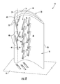
- Fig. 3 provides a perspective view of the airfoil 10 according to a second embodiment of the present invention.
- the airfoil 10 again includes the platform or sidewall 12, interior surface 16, exterior surface 18, pressure side 20, suction side 22, overlapping pressure side trench segments 46, and side cooling passages 58 as previously described and illustrated in Fig. 1 .
- the overlapping stagnation trench segments 40 lie along at least a portion of the stagnation line 24 and then curve in alternating directions toward the pressure and suctions sides 20, 22.
- the stagnation trench segments 40 may include a branch at a discreet angle and then continue as a straight trench.
- the cooling passages 44 in each stagnation trench segment 40 again provide fluid communication from the interior surface 16 to the exterior surface 18 to enhance film cooling through the stagnation trench segments 40 along the stagnation line 24.
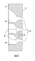
- each trench segment 40, 46, 50 generally includes opposing walls 62 that define a depression or groove in the exterior surface 18.
- the opposing walls 62 may be straight or curved and may define a constant or varying width for the trench segments 40, 46, 50.
- the cooling passages 44, 58 in adjacent trench segments 40, 46, 50 may be radially aligned with or offset from one another.
- Each cooling passage 44, 58 may include a first section 64 that terminates at the interior surface 16 and a second section 66 that terminates at the exterior surface 18.
- the first section 64 may have a cylindrical shape, and the second section 66 may have a conical or spherical shape. As shown in Fig. 5 , the first section 64 may be angled with respect to the second section 66 and/or the trench segment 40, 46, 50 to provide directional flow for the cooling media flowing through the cooling passage 44, 58 and into the trench segment 40, 46, 50. Alternately or in addition, the second section 66 and/or the walls 62 of the trench segment 40, 46, 50 may be asymmetric to preferentially distribute the cooling media across the exterior surface 18.
- One or more of the cooling passages 44, 58 may be angled with respect to the trench segments 40, 46, 50 to preferentially direct the cooling media in the trench segments 40, 46, 50.
- the cooling passages 44 in the stagnation trench segments 40 may be angled radially outward so that the cooling media flows radially outward in the stagnation trench segments 40.
- the depth of the stagnation trench segments 40 may gradually decrease and/or the width may gradually increase as the stagnation trench segments 40 extend radially outward. In this manner, the angled cooling passages 44, in combination with the varying width and/or depth of the trench segments 40, enhance the distribution of the cooling media along the exterior surface 18.
- each stagnation trench segment 40 again lies along at least a portion of the stagnation line 24 and branch portions 70 extend at angles in opposite directions toward the pressure and suction sides 20, 22 of the airfoil 10. In this manner, the branch portions 70 radially overlap with the next radially outward stagnation trench segment 40 to enhance distribution of the film cooling across the exterior surface 18 of the airfoil 10.
- each stagnation trench segment 40 again includes the branch portions 70 that extend at angles in opposite directions toward the pressure and suction sides 20, 22 of the airfoil 10, as previously shown in Fig. 6 .
- each stagnation trench segment 40 again includes the branch portions 70; however, the branch portions 70 extend at angles in alternating directions toward the pressure and suction sides 20, 22 of the airfoil 10.
- the stagnation trench segment 40 may include multiple cooling passages 44, with each cooling passage located radially between consecutive branch portions 70.
- Fig. 9 provides an additional embodiment of the pressure side trench segments 46 that may or may not be incorporated into any of the previous embodiments.
- the overlapping pressure side trench segments 46 may be aligned substantially perpendicular to the direction of airflow across the airfoil 10, and each pressure side trench segment 46 may further include one or more branch portions 72 that extend at an angle toward the trailing edge 26. In this manner, the branch portions 72 radially overlap with the next radially outward pressure side trench segment 46 to enhance distribution of the film cooling across the pressure side 20 of the airfoil 10.
- the airfoil 10 may similarly include suction side trench segments 50 with similar branch portions 72 that extend at an angle toward the trailing edge 26 on the suction side 22 of the exterior surface 18.
- suction side trench segments 50 with similar branch portions 72 that extend at an angle toward the trailing edge 26 on the suction side 22 of the exterior surface 18.
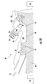
- Fig. 10 provides a simplified cross-section view of an exemplary gas turbine 80 that may incorporate various embodiments of the present invention.
- the gas turbine 80 may generally include a compressor section 82 at the front, a combustion section 84 radially disposed around the middle, and a turbine section 86 at the rear.
- the compressor section 82 and the turbine section 86 may share a common rotor 88 connected to a generator 90 to produce electricity.
- the compressor section 82 may include an axial flow compressor in which a working fluid 92, such as ambient air, enters the compressor and passes through alternating stages of stationary vanes 94 and rotating blades 96.
- a compressor casing 98 may contain the working fluid 92 as the stationary vanes 94 and rotating blades 96 accelerate and redirect the working fluid 92 to produce a continuous flow of compressed working fluid 92.
- the majority of the compressed working fluid 92 flows through a compressor discharge plenum 100 to the combustion section 84.
- the combustion section 84 may include any type of combustor known in the art.
- a combustor casing 102 may circumferentially surround some or all of the combustion section 84 to contain the compressed working fluid 92 flowing from the compressor section 82.
- One or more fuel nozzles 104 may be radially arranged in an end cover 106 to supply fuel to a combustion chamber 108 downstream from the fuel nozzles 104.
- Possible fuels include, for example, one or more of blast furnace gas, coke oven gas, natural gas, vaporized liquefied natural gas (LNG), hydrogen, and propane.
- the compressed working fluid 92 may flow from the compressor discharge passage 100 along the outside of the combustion chamber 108 before reaching the end cover 106 and reversing direction to flow through the fuel nozzles 104 to mix with the fuel.
- the mixture of fuel and compressed working fluid 92 flows into the combustion chamber 108 where it ignites to generate combustion gases having a high temperature and pressure.
- a transition duct 110 circumferentially surrounds at least a portion of the combustion chamber 108, and the combustion gases flow through the transition duct 110 to the turbine section 86.
- the turbine section 86 may include alternating stages of rotating buckets 112 and stationary nozzles 114.
- the transition duct 110 redirects and focuses the combustion gases onto the first stage of rotating buckets 112.
- the combustion gases expand, causing the rotating buckets 112 and rotor 88 to rotate.
- the combustion gases then flow to the next stage of stationary nozzles 114 which redirect the combustion gases to the next stage of rotating buckets 112, and the process repeats for the following stages.
Landscapes
- Engineering & Computer Science (AREA)
- Mechanical Engineering (AREA)
- General Engineering & Computer Science (AREA)
- Turbine Rotor Nozzle Sealing (AREA)
- Braking Arrangements (AREA)
Claims (8)
- Profil aérodynamique (10), comprenant :a. une surface interne (16) ;b. une surface externe (18) opposée à la surface interne (16), dans lequel la surface externe (18) comprend un côté de refoulement (20), un côté d'aspiration (22) opposé au côté de refoulement (20), une ligne d'arrêt (24) entre les côtés de refoulement et d'aspiration (20, 22) et un bord de fuite (26) entre les côtés de refoulement et d'aspiration (20, 22) et en aval de la ligne d'arrêt (24) ;c. une première colonne (42) de segments de tranchée d'arrêt chevauchants (40) sur la surface externe (18), dans lequel la ligne d'arrêt (24) passe à travers au moins une partie de chacun des segments de tranchée d'arrêt chevauchants (40) ; etd. au moins un passage de refroidissement (44) dans chaque segment de tranchée d'arrêt (40), dans lequel les passages de refroidissement (44) assurent une communication fluidique entre la surface interne (16) et la surface externe (18).
- Profil aérodynamique (10) selon la revendication 1, dans lequel au moins un segment de tranchée d'arrêt (40) est arqué.
- Profil aérodynamique (10) selon la revendication 1 ou la revendication 2, dans lequel au moins un segment de tranchée d'arrêt (40) a une dimension variable sur une longueur (30, 32) du au moins un segment de tranchée d'arrêt (40).
- Profil aérodynamique (10) selon la revendication 1, 2 ou 3, dans lequel au moins un segment de tranchée d'arrêt (40) a une dimension décroissante et le au moins un passage de refroidissement (44) du au moins un segment de tranchée d'arrêt (40) est incliné vers la dimension décroissante.
- Profil aérodynamique (10) selon l'une quelconque des revendications précédentes, comprenant en outre une deuxième colonne (48) de segments de tranchée chevauchants côté refoulement (46) sur le côté de refoulement (20).
- Profil aérodynamique (10) selon la revendication 5 comprenant une troisième colonne (52) de segments de tranchée chevauchants côté aspiration (50) sur le côté d'aspiration (22).
- Profil aérodynamique selon l'une quelconque des revendications 5 ou 6, comprenant en outre au moins un passage de refroidissement latéral (58) dans chaque segment de tranchée côté refoulement (46), dans lequel les passages de refroidissement latéraux (58) assurent une communication fluidique entre la surface interne (16) et la surface externe (18).
- Profil aérodynamique (10) selon la revendication 7, dans lequel les passages de refroidissement latéraux (58) des segments de tranchée côté refoulement (46) sont décalés radialement des passages de refroidissement (58) des segments de tranchée d'arrêt (40).
Applications Claiming Priority (1)
| Application Number | Priority Date | Filing Date | Title |
|---|---|---|---|
| US13/535,540 US9080451B2 (en) | 2012-06-28 | 2012-06-28 | Airfoil |
Publications (2)
| Publication Number | Publication Date |
|---|---|
| EP2679772A1 EP2679772A1 (fr) | 2014-01-01 |
| EP2679772B1 true EP2679772B1 (fr) | 2015-05-27 |
Family
ID=48740854
Family Applications (1)
| Application Number | Title | Priority Date | Filing Date |
|---|---|---|---|
| EP13172933.7A Active EP2679772B1 (fr) | 2012-06-28 | 2013-06-20 | Surface portante |
Country Status (5)
| Country | Link |
|---|---|
| US (1) | US9080451B2 (fr) |
| EP (1) | EP2679772B1 (fr) |
| JP (1) | JP6216166B2 (fr) |
| CN (1) | CN103527260B (fr) |
| RU (1) | RU2611465C2 (fr) |
Families Citing this family (15)
| Publication number | Priority date | Publication date | Assignee | Title |
|---|---|---|---|---|
| CN105339593B (zh) * | 2013-07-03 | 2017-10-13 | 通用电气公司 | 翼形件结构的沟槽冷却 |
| JP5705945B1 (ja) * | 2013-10-28 | 2015-04-22 | ミネベア株式会社 | 遠心式ファン |
| US10041356B2 (en) * | 2014-08-15 | 2018-08-07 | United Technologies Corporation | Showerhead hole scheme apparatus and system |
| US20160169004A1 (en) | 2014-12-15 | 2016-06-16 | United Technologies Corporation | Cooling passages for gas turbine engine component |
| US9976423B2 (en) * | 2014-12-23 | 2018-05-22 | United Technologies Corporation | Airfoil showerhead pattern apparatus and system |
| US10451084B2 (en) * | 2015-11-16 | 2019-10-22 | General Electric Company | Gas turbine engine with vane having a cooling inlet |
| US10280763B2 (en) * | 2016-06-08 | 2019-05-07 | Ansaldo Energia Switzerland AG | Airfoil cooling passageways for generating improved protective film |
| KR101853550B1 (ko) * | 2016-08-22 | 2018-04-30 | 두산중공업 주식회사 | 가스 터빈 블레이드 |
| US20180230812A1 (en) * | 2017-01-13 | 2018-08-16 | General Electric Company | Film hole arrangement for a turbine engine |
| US10697301B2 (en) | 2017-04-07 | 2020-06-30 | General Electric Company | Turbine engine airfoil having a cooling circuit |
| US10570747B2 (en) * | 2017-10-02 | 2020-02-25 | DOOSAN Heavy Industries Construction Co., LTD | Enhanced film cooling system |
| US11401818B2 (en) * | 2018-08-06 | 2022-08-02 | General Electric Company | Turbomachine cooling trench |
| CN113898415B (zh) * | 2021-10-15 | 2022-06-28 | 上海交通大学 | 用于提高低压涡轮叶片气动效率的结构及其工作方法 |
| US11971170B1 (en) * | 2022-12-30 | 2024-04-30 | Ge Infrastructure Technology Llc | System and method having flame stabilizers for isothermal expansion in turbine stage of gas turbine engine |
| US12037951B1 (en) | 2022-12-30 | 2024-07-16 | Ge Infrastructure Technology Llc | System and method having load control for isothermal expansion in turbine stage of gas turbine engine |
Family Cites Families (18)
| Publication number | Priority date | Publication date | Assignee | Title |
|---|---|---|---|---|
| US5486093A (en) * | 1993-09-08 | 1996-01-23 | United Technologies Corporation | Leading edge cooling of turbine airfoils |
| US5374162A (en) | 1993-11-30 | 1994-12-20 | United Technologies Corporation | Airfoil having coolable leading edge region |
| US5458461A (en) | 1994-12-12 | 1995-10-17 | General Electric Company | Film cooled slotted wall |
| US6050777A (en) | 1997-12-17 | 2000-04-18 | United Technologies Corporation | Apparatus and method for cooling an airfoil for a gas turbine engine |
| US6164912A (en) | 1998-12-21 | 2000-12-26 | United Technologies Corporation | Hollow airfoil for a gas turbine engine |
| US6210111B1 (en) | 1998-12-21 | 2001-04-03 | United Technologies Corporation | Turbine blade with platform cooling |
| US6234755B1 (en) * | 1999-10-04 | 2001-05-22 | General Electric Company | Method for improving the cooling effectiveness of a gaseous coolant stream, and related articles of manufacture |
| US6994521B2 (en) * | 2003-03-12 | 2006-02-07 | Florida Turbine Technologies, Inc. | Leading edge diffusion cooling of a turbine airfoil for a gas turbine engine |
| RU2267616C1 (ru) * | 2004-05-21 | 2006-01-10 | Федеральное государственное унитарное предприятие "Центральный институт авиационного моторостроения им. П.И. Баранова" | Охлаждаемая лопатка турбины |
| US7553534B2 (en) * | 2006-08-29 | 2009-06-30 | General Electric Company | Film cooled slotted wall and method of making the same |
| US20090246011A1 (en) * | 2008-03-25 | 2009-10-01 | General Electric Company | Film cooling of turbine components |
| US8105030B2 (en) | 2008-08-14 | 2012-01-31 | United Technologies Corporation | Cooled airfoils and gas turbine engine systems involving such airfoils |
| US8087893B1 (en) | 2009-04-03 | 2012-01-03 | Florida Turbine Technologies, Inc. | Turbine blade with showerhead film cooling holes |
| US20110097188A1 (en) * | 2009-10-23 | 2011-04-28 | General Electric Company | Structure and method for improving film cooling using shallow trench with holes oriented along length of trench |
| US8608443B2 (en) * | 2010-06-11 | 2013-12-17 | Siemens Energy, Inc. | Film cooled component wall in a turbine engine |
| JP5517163B2 (ja) * | 2010-10-07 | 2014-06-11 | 株式会社日立製作所 | タービン翼の冷却孔加工方法 |
| US8870535B2 (en) * | 2012-01-13 | 2014-10-28 | General Electric Company | Airfoil |
| US8870536B2 (en) * | 2012-01-13 | 2014-10-28 | General Electric Company | Airfoil |
-
2012
- 2012-06-28 US US13/535,540 patent/US9080451B2/en active Active
-
2013
- 2013-06-20 EP EP13172933.7A patent/EP2679772B1/fr active Active
- 2013-06-24 JP JP2013131234A patent/JP6216166B2/ja not_active Expired - Fee Related
- 2013-06-27 RU RU2013129242A patent/RU2611465C2/ru not_active IP Right Cessation
- 2013-06-28 CN CN201310268845.4A patent/CN103527260B/zh not_active Expired - Fee Related
Also Published As
| Publication number | Publication date |
|---|---|
| US9080451B2 (en) | 2015-07-14 |
| CN103527260A (zh) | 2014-01-22 |
| RU2013129242A (ru) | 2015-01-10 |
| JP6216166B2 (ja) | 2017-10-18 |
| EP2679772A1 (fr) | 2014-01-01 |
| RU2611465C2 (ru) | 2017-02-22 |
| JP2014009689A (ja) | 2014-01-20 |
| US20140003960A1 (en) | 2014-01-02 |
| CN103527260B (zh) | 2017-03-01 |
Similar Documents
| Publication | Publication Date | Title |
|---|---|---|
| EP2679772B1 (fr) | Surface portante | |
| EP2615244B1 (fr) | Aube de turbine refroidie par couche d'air comportant une pluralité de rainures à la surface extérieure | |
| US20240159151A1 (en) | Airfoil for a turbine engine | |
| EP2615245B1 (fr) | Aube de turbine refroidie par couche d'air comportant des segments de rainure à la surface extérieure | |
| CN106894847B (zh) | 涡轮机及其涡轮喷嘴 | |
| JP6650687B2 (ja) | ロータブレード冷却 | |
| JP2010156335A (ja) | 改良型タービン翼プラットフォームの輪郭に関する方法および装置 | |
| CN107084004B (zh) | 用于涡轮发动机部件的冲击孔 | |
| CN106894843B (zh) | 涡轮机及其涡轮叶片 | |
| EP3047104B1 (fr) | Turbomachine avec paroi contourée | |
| US20150013345A1 (en) | Gas turbine shroud cooling | |
| US20170145831A1 (en) | Gas turbine engine with film holes | |
| CA2927035C (fr) | Assemblage de rotor dote d'un element d'usure | |
| CA2927037C (fr) | Assemblage de rotor dote de godet | |
| JP6446174B2 (ja) | コンプレッサフェアリングセグメント | |
| US10370987B2 (en) | Blade or vane row and gas turbine | |
| EP3186484B1 (fr) | Turbine à gaz | |
| EP3184736B1 (fr) | Caisson de transfert de chaleur en biais | |
| EP3196411A2 (fr) | Dispositifs d'alignement d'écoulement pour améliorer la performance de diffuseur | |
| US20180230812A1 (en) | Film hole arrangement for a turbine engine | |
| CN103206261B (zh) | 翼型件 |
Legal Events
| Date | Code | Title | Description |
|---|---|---|---|
| PUAI | Public reference made under article 153(3) epc to a published international application that has entered the european phase |
Free format text: ORIGINAL CODE: 0009012 |
|
| AK | Designated contracting states |
Kind code of ref document: A1 Designated state(s): AL AT BE BG CH CY CZ DE DK EE ES FI FR GB GR HR HU IE IS IT LI LT LU LV MC MK MT NL NO PL PT RO RS SE SI SK SM TR |
|
| AX | Request for extension of the european patent |
Extension state: BA ME |
|
| 17P | Request for examination filed |
Effective date: 20140701 |
|
| RBV | Designated contracting states (corrected) |
Designated state(s): AL AT BE BG CH CY CZ DE DK EE ES FI FR GB GR HR HU IE IS IT LI LT LU LV MC MK MT NL NO PL PT RO RS SE SI SK SM TR |
|
| RIC1 | Information provided on ipc code assigned before grant |
Ipc: F01D 5/18 20060101AFI20141216BHEP |
|
| GRAP | Despatch of communication of intention to grant a patent |
Free format text: ORIGINAL CODE: EPIDOSNIGR1 |
|
| INTG | Intention to grant announced |
Effective date: 20150129 |
|
| GRAS | Grant fee paid |
Free format text: ORIGINAL CODE: EPIDOSNIGR3 |
|
| GRAA | (expected) grant |
Free format text: ORIGINAL CODE: 0009210 |
|
| AK | Designated contracting states |
Kind code of ref document: B1 Designated state(s): AL AT BE BG CH CY CZ DE DK EE ES FI FR GB GR HR HU IE IS IT LI LT LU LV MC MK MT NL NO PL PT RO RS SE SI SK SM TR |
|
| REG | Reference to a national code |
Ref country code: GB Ref legal event code: FG4D |
|
| REG | Reference to a national code |
Ref country code: CH Ref legal event code: EP |
|
| REG | Reference to a national code |
Ref country code: AT Ref legal event code: REF Ref document number: 728982 Country of ref document: AT Kind code of ref document: T Effective date: 20150615 |
|
| REG | Reference to a national code |
Ref country code: IE Ref legal event code: FG4D |
|
| REG | Reference to a national code |
Ref country code: DE Ref legal event code: R096 Ref document number: 602013001838 Country of ref document: DE |
|
| REG | Reference to a national code |
Ref country code: AT Ref legal event code: MK05 Ref document number: 728982 Country of ref document: AT Kind code of ref document: T Effective date: 20150527 |
|
| REG | Reference to a national code |
Ref country code: LT Ref legal event code: MG4D |
|
| PG25 | Lapsed in a contracting state [announced via postgrant information from national office to epo] |
Ref country code: HR Free format text: LAPSE BECAUSE OF FAILURE TO SUBMIT A TRANSLATION OF THE DESCRIPTION OR TO PAY THE FEE WITHIN THE PRESCRIBED TIME-LIMIT Effective date: 20150527 Ref country code: NO Free format text: LAPSE BECAUSE OF FAILURE TO SUBMIT A TRANSLATION OF THE DESCRIPTION OR TO PAY THE FEE WITHIN THE PRESCRIBED TIME-LIMIT Effective date: 20150827 Ref country code: LT Free format text: LAPSE BECAUSE OF FAILURE TO SUBMIT A TRANSLATION OF THE DESCRIPTION OR TO PAY THE FEE WITHIN THE PRESCRIBED TIME-LIMIT Effective date: 20150527 Ref country code: FI Free format text: LAPSE BECAUSE OF FAILURE TO SUBMIT A TRANSLATION OF THE DESCRIPTION OR TO PAY THE FEE WITHIN THE PRESCRIBED TIME-LIMIT Effective date: 20150527 Ref country code: ES Free format text: LAPSE BECAUSE OF FAILURE TO SUBMIT A TRANSLATION OF THE DESCRIPTION OR TO PAY THE FEE WITHIN THE PRESCRIBED TIME-LIMIT Effective date: 20150527 Ref country code: PT Free format text: LAPSE BECAUSE OF FAILURE TO SUBMIT A TRANSLATION OF THE DESCRIPTION OR TO PAY THE FEE WITHIN THE PRESCRIBED TIME-LIMIT Effective date: 20150928 |
|
| REG | Reference to a national code |
Ref country code: NL Ref legal event code: MP Effective date: 20150527 |
|
| PG25 | Lapsed in a contracting state [announced via postgrant information from national office to epo] |
Ref country code: LV Free format text: LAPSE BECAUSE OF FAILURE TO SUBMIT A TRANSLATION OF THE DESCRIPTION OR TO PAY THE FEE WITHIN THE PRESCRIBED TIME-LIMIT Effective date: 20150527 Ref country code: AT Free format text: LAPSE BECAUSE OF FAILURE TO SUBMIT A TRANSLATION OF THE DESCRIPTION OR TO PAY THE FEE WITHIN THE PRESCRIBED TIME-LIMIT Effective date: 20150527 Ref country code: GR Free format text: LAPSE BECAUSE OF FAILURE TO SUBMIT A TRANSLATION OF THE DESCRIPTION OR TO PAY THE FEE WITHIN THE PRESCRIBED TIME-LIMIT Effective date: 20150828 Ref country code: BG Free format text: LAPSE BECAUSE OF FAILURE TO SUBMIT A TRANSLATION OF THE DESCRIPTION OR TO PAY THE FEE WITHIN THE PRESCRIBED TIME-LIMIT Effective date: 20150827 Ref country code: IS Free format text: LAPSE BECAUSE OF FAILURE TO SUBMIT A TRANSLATION OF THE DESCRIPTION OR TO PAY THE FEE WITHIN THE PRESCRIBED TIME-LIMIT Effective date: 20150927 Ref country code: RS Free format text: LAPSE BECAUSE OF FAILURE TO SUBMIT A TRANSLATION OF THE DESCRIPTION OR TO PAY THE FEE WITHIN THE PRESCRIBED TIME-LIMIT Effective date: 20150527 |
|
| PG25 | Lapsed in a contracting state [announced via postgrant information from national office to epo] |
Ref country code: DK Free format text: LAPSE BECAUSE OF FAILURE TO SUBMIT A TRANSLATION OF THE DESCRIPTION OR TO PAY THE FEE WITHIN THE PRESCRIBED TIME-LIMIT Effective date: 20150527 Ref country code: EE Free format text: LAPSE BECAUSE OF FAILURE TO SUBMIT A TRANSLATION OF THE DESCRIPTION OR TO PAY THE FEE WITHIN THE PRESCRIBED TIME-LIMIT Effective date: 20150527 Ref country code: IT Free format text: LAPSE BECAUSE OF FAILURE TO SUBMIT A TRANSLATION OF THE DESCRIPTION OR TO PAY THE FEE WITHIN THE PRESCRIBED TIME-LIMIT Effective date: 20150527 |
|
| PG25 | Lapsed in a contracting state [announced via postgrant information from national office to epo] |
Ref country code: CZ Free format text: LAPSE BECAUSE OF FAILURE TO SUBMIT A TRANSLATION OF THE DESCRIPTION OR TO PAY THE FEE WITHIN THE PRESCRIBED TIME-LIMIT Effective date: 20150527 Ref country code: MC Free format text: LAPSE BECAUSE OF FAILURE TO SUBMIT A TRANSLATION OF THE DESCRIPTION OR TO PAY THE FEE WITHIN THE PRESCRIBED TIME-LIMIT Effective date: 20150527 Ref country code: SK Free format text: LAPSE BECAUSE OF FAILURE TO SUBMIT A TRANSLATION OF THE DESCRIPTION OR TO PAY THE FEE WITHIN THE PRESCRIBED TIME-LIMIT Effective date: 20150527 Ref country code: PL Free format text: LAPSE BECAUSE OF FAILURE TO SUBMIT A TRANSLATION OF THE DESCRIPTION OR TO PAY THE FEE WITHIN THE PRESCRIBED TIME-LIMIT Effective date: 20150527 Ref country code: RO Free format text: LAPSE BECAUSE OF NON-PAYMENT OF DUE FEES Effective date: 20150527 |
|
| REG | Reference to a national code |
Ref country code: DE Ref legal event code: R097 Ref document number: 602013001838 Country of ref document: DE |
|
| REG | Reference to a national code |
Ref country code: IE Ref legal event code: MM4A |
|
| PLBE | No opposition filed within time limit |
Free format text: ORIGINAL CODE: 0009261 |
|
| STAA | Information on the status of an ep patent application or granted ep patent |
Free format text: STATUS: NO OPPOSITION FILED WITHIN TIME LIMIT |
|
| PG25 | Lapsed in a contracting state [announced via postgrant information from national office to epo] |
Ref country code: IE Free format text: LAPSE BECAUSE OF NON-PAYMENT OF DUE FEES Effective date: 20150620 |
|
| 26N | No opposition filed |
Effective date: 20160301 |
|
| PG25 | Lapsed in a contracting state [announced via postgrant information from national office to epo] |
Ref country code: SI Free format text: LAPSE BECAUSE OF FAILURE TO SUBMIT A TRANSLATION OF THE DESCRIPTION OR TO PAY THE FEE WITHIN THE PRESCRIBED TIME-LIMIT Effective date: 20150527 |
|
| PG25 | Lapsed in a contracting state [announced via postgrant information from national office to epo] |
Ref country code: BE Free format text: LAPSE BECAUSE OF FAILURE TO SUBMIT A TRANSLATION OF THE DESCRIPTION OR TO PAY THE FEE WITHIN THE PRESCRIBED TIME-LIMIT Effective date: 20150527 |
|
| REG | Reference to a national code |
Ref country code: FR Ref legal event code: ST Effective date: 20160805 |
|
| PG25 | Lapsed in a contracting state [announced via postgrant information from national office to epo] |
Ref country code: FR Free format text: LAPSE BECAUSE OF NON-PAYMENT OF DUE FEES Effective date: 20150727 |
|
| PG25 | Lapsed in a contracting state [announced via postgrant information from national office to epo] |
Ref country code: MT Free format text: LAPSE BECAUSE OF FAILURE TO SUBMIT A TRANSLATION OF THE DESCRIPTION OR TO PAY THE FEE WITHIN THE PRESCRIBED TIME-LIMIT Effective date: 20150527 |
|
| PG25 | Lapsed in a contracting state [announced via postgrant information from national office to epo] |
Ref country code: HU Free format text: LAPSE BECAUSE OF FAILURE TO SUBMIT A TRANSLATION OF THE DESCRIPTION OR TO PAY THE FEE WITHIN THE PRESCRIBED TIME-LIMIT; INVALID AB INITIO Effective date: 20130620 |
|
| PG25 | Lapsed in a contracting state [announced via postgrant information from national office to epo] |
Ref country code: CY Free format text: LAPSE BECAUSE OF FAILURE TO SUBMIT A TRANSLATION OF THE DESCRIPTION OR TO PAY THE FEE WITHIN THE PRESCRIBED TIME-LIMIT Effective date: 20150527 Ref country code: SE Free format text: LAPSE BECAUSE OF FAILURE TO SUBMIT A TRANSLATION OF THE DESCRIPTION OR TO PAY THE FEE WITHIN THE PRESCRIBED TIME-LIMIT Effective date: 20150527 Ref country code: NL Free format text: LAPSE BECAUSE OF FAILURE TO SUBMIT A TRANSLATION OF THE DESCRIPTION OR TO PAY THE FEE WITHIN THE PRESCRIBED TIME-LIMIT Effective date: 20150527 |
|
| PG25 | Lapsed in a contracting state [announced via postgrant information from national office to epo] |
Ref country code: TR Free format text: LAPSE BECAUSE OF FAILURE TO SUBMIT A TRANSLATION OF THE DESCRIPTION OR TO PAY THE FEE WITHIN THE PRESCRIBED TIME-LIMIT Effective date: 20150527 |
|
| PG25 | Lapsed in a contracting state [announced via postgrant information from national office to epo] |
Ref country code: LU Free format text: LAPSE BECAUSE OF NON-PAYMENT OF DUE FEES Effective date: 20150620 |
|
| GBPC | Gb: european patent ceased through non-payment of renewal fee |
Effective date: 20170620 |
|
| PG25 | Lapsed in a contracting state [announced via postgrant information from national office to epo] |
Ref country code: GB Free format text: LAPSE BECAUSE OF NON-PAYMENT OF DUE FEES Effective date: 20170620 |
|
| PG25 | Lapsed in a contracting state [announced via postgrant information from national office to epo] |
Ref country code: SM Free format text: LAPSE BECAUSE OF FAILURE TO SUBMIT A TRANSLATION OF THE DESCRIPTION OR TO PAY THE FEE WITHIN THE PRESCRIBED TIME-LIMIT Effective date: 20150527 |
|
| PG25 | Lapsed in a contracting state [announced via postgrant information from national office to epo] |
Ref country code: MK Free format text: LAPSE BECAUSE OF FAILURE TO SUBMIT A TRANSLATION OF THE DESCRIPTION OR TO PAY THE FEE WITHIN THE PRESCRIBED TIME-LIMIT Effective date: 20150527 |
|
| PG25 | Lapsed in a contracting state [announced via postgrant information from national office to epo] |
Ref country code: AL Free format text: LAPSE BECAUSE OF FAILURE TO SUBMIT A TRANSLATION OF THE DESCRIPTION OR TO PAY THE FEE WITHIN THE PRESCRIBED TIME-LIMIT Effective date: 20150527 |
|
| PGFP | Annual fee paid to national office [announced via postgrant information from national office to epo] |
Ref country code: DE Payment date: 20220518 Year of fee payment: 10 |
|
| PGFP | Annual fee paid to national office [announced via postgrant information from national office to epo] |
Ref country code: CH Payment date: 20220702 Year of fee payment: 10 |
|
| REG | Reference to a national code |
Ref country code: DE Ref legal event code: R119 Ref document number: 602013001838 Country of ref document: DE |
|
| REG | Reference to a national code |
Ref country code: CH Ref legal event code: PL |
|
| PG25 | Lapsed in a contracting state [announced via postgrant information from national office to epo] |
Ref country code: DE Free format text: LAPSE BECAUSE OF NON-PAYMENT OF DUE FEES Effective date: 20240103 Ref country code: CH Free format text: LAPSE BECAUSE OF NON-PAYMENT OF DUE FEES Effective date: 20230630 |