EP2679760A2 - A window and a screening arrangement comprising a screening device and improved engagement means, and a method for operating the screening arrangement - Google Patents
A window and a screening arrangement comprising a screening device and improved engagement means, and a method for operating the screening arrangement Download PDFInfo
- Publication number
- EP2679760A2 EP2679760A2 EP13173331.3A EP13173331A EP2679760A2 EP 2679760 A2 EP2679760 A2 EP 2679760A2 EP 13173331 A EP13173331 A EP 13173331A EP 2679760 A2 EP2679760 A2 EP 2679760A2
- Authority
- EP
- European Patent Office
- Prior art keywords
- engagement means
- screening
- sash
- engagement
- frame
- Prior art date
- Legal status (The legal status is an assumption and is not a legal conclusion. Google has not performed a legal analysis and makes no representation as to the accuracy of the status listed.)
- Granted
Links
Images










Classifications
-
- E—FIXED CONSTRUCTIONS
- E06—DOORS, WINDOWS, SHUTTERS, OR ROLLER BLINDS IN GENERAL; LADDERS
- E06B—FIXED OR MOVABLE CLOSURES FOR OPENINGS IN BUILDINGS, VEHICLES, FENCES OR LIKE ENCLOSURES IN GENERAL, e.g. DOORS, WINDOWS, BLINDS, GATES
- E06B9/00—Screening or protective devices for wall or similar openings, with or without operating or securing mechanisms; Closures of similar construction
- E06B9/02—Shutters, movable grilles, or other safety closing devices, e.g. against burglary
- E06B9/08—Roll-type closures
- E06B9/11—Roller shutters
-
- E—FIXED CONSTRUCTIONS
- E06—DOORS, WINDOWS, SHUTTERS, OR ROLLER BLINDS IN GENERAL; LADDERS
- E06B—FIXED OR MOVABLE CLOSURES FOR OPENINGS IN BUILDINGS, VEHICLES, FENCES OR LIKE ENCLOSURES IN GENERAL, e.g. DOORS, WINDOWS, BLINDS, GATES
- E06B9/00—Screening or protective devices for wall or similar openings, with or without operating or securing mechanisms; Closures of similar construction
- E06B9/56—Operating, guiding or securing devices or arrangements for roll-type closures; Spring drums; Tape drums; Counterweighting arrangements therefor
-
- E—FIXED CONSTRUCTIONS
- E06—DOORS, WINDOWS, SHUTTERS, OR ROLLER BLINDS IN GENERAL; LADDERS
- E06B—FIXED OR MOVABLE CLOSURES FOR OPENINGS IN BUILDINGS, VEHICLES, FENCES OR LIKE ENCLOSURES IN GENERAL, e.g. DOORS, WINDOWS, BLINDS, GATES
- E06B9/00—Screening or protective devices for wall or similar openings, with or without operating or securing mechanisms; Closures of similar construction
- E06B9/56—Operating, guiding or securing devices or arrangements for roll-type closures; Spring drums; Tape drums; Counterweighting arrangements therefor
- E06B9/92—Means allowing the closures to be shifted out of the plane of the opening
Definitions
- the present invention relates to a window comprising a frame and a sash, each having a top member, a bottom member and two side members, said sash being pivotally connected to the frame substantially at a centre axis, and a screening arrangement including a screening device with a top element mounted at the top member of the frame, two side rails, and a screening body, said screening body being adapted to be brought from a non-screening to a screening position from the top element, and at least one set of engagement means to provide operation of the screening arrangement, said set of engagement means including a first engagement means connected to the screening arrangement and a second engagement means.
- the invention furthermore relates to a screening arrangement, and to a method for operating a screening arrangement.
- Such screening arrangements including screening devices in the form of roller shutters are traditionally used for screening an aperture of a building structure, most often the light-admitting aperture of windows, but also of doors and other building openings.
- the roller shutters are either installed to extend substantially vertically in a building façade, or in an obliquely positioned roof window installed in an inclined roof surface, or as a horizontally extending cover for openings in a horizontal surface.
- the screening body is normally rolled up on a roller bar accommodated in the top element of the roller shutter.
- the rolling up of the screening body may be effected either by a spring bias in the roller bar or by a drive motor.
- the unrolling of vertically situated roller shutters is normally effected in that the screening body moves by means of the gravity in the direction of the bottom of the aperture during simultaneous successive unrolling of the slats from the roller bar, and in roller shutters installed in for instance roof windows in an inclined roof, the unrolling normally takes place by means of drive devices.
- a window of the kind mentioned in the introduction which is furthermore characterized in that said second engagement means is provided at the bottom member of the sash, and that operation of the screening body between the non-screening and the screening position is carried out by pivoting the sash to enable engagement of the second engagement means with the first engagement means.
- the first engagement means and the second engagement means are coupled so that the sash may be used as an operating means for operating the screening body of the screening arrangement.
- This is generally achieved by positioning the second engagement means on the lower portion of the sash where the bottom member is positioned, e.g. on the bottom member of the sash or on a side member of the sash.
- the position of the first engagement means on the screening device is adjusted, so that when the sash with the second engagement means is pivoted the desired engagement between the first and second engagement means may be achieved.
- the engagement and disengagement may be carried out manually or automatically.
- the engagement of the second engagement means with the first engagement means is adapted to be carried out automatically.
- automated in the present context is to be understood that the engagement occurs as a result of the movement of the sash relative to the frame, i.e. coupling of the first and second engagement means is established at the final stage of pivoting the sash in which the sash bottom member is brought to a position at or near with the frame top member without a user operating the set of engagement means.
- the sash bottom member and frame top member should be moved into such into close proximity that the first engagement means may engage the second engagement means.
- the sash in which the engagement is carried out manually, the sash is operated to a position where the bottom member of the sash is located at or near the frame top member and hence the top element of the screening device, and the set of engagement means is manually engaged by the user of the window.
- the engagement is carried out manually the user of the window must manually engage the engagement means e.g. by manually engaging the engagement means or by unfixing the screening body from the top element so that it may be moved to the screening position.
- the disengagement of the second engagement means from the first engagement means is adapted to be carried out automatically.
- the disengagement occurs as a result of the movement of the sash relative to the frame, i.e. decoupling of the first and second engagement means is established at the final stage of pivoting the sash in which the sash bottom member is brought to a position at or near with the frame top member without a user operating the set of engagement means.
- automatic should in the present context also be interpreted as encompassing any operations not requiring the direct intervention of a user to occur.
- Other such automatic or semi-automatic operations include embodiments, in which for instance the sash is moved further in the pivoting movement relative to the frame during disengagement than during engagement, and the possibility of manual synchronization of the set of engagement means.
- the user of the window When the disengagement is carried out manually the user of the window must manually disengage the engagement means e.g. by manually disengaging the engagement means or by fixing the screening body to the top element.
- the sash is operated to a position where the bottom member of the sash is located at or near the frame top member and hence the top element of the screening device. If the sash returns to this position with the screening body from a screening position, the screening body is returned to the non-screening position in the top element and the set of engagement means is configured to disengage when the screening body has reached the non-screening position.
- the set of engagement means is configured to engage so that when the sash is returned to a closed position the screening body is brought from the non-screening position to the screening position.
- Embodiments combining automatic or manual engagement and automatic or manual engagement is conceivable as well.
- the first engagement means comprises at least one hook and a locking and release mechanism
- the second engagement means comprises at least one block including a hook portion and an inclined portion.
- the first engagement means comprises a longitudinally extending profile and an end piece at each end of the profile, one hook being connected to a respective end piece.
- the second engagement means comprises a longitudinally extending bar and a mounting fitting at each end of the bar, one block being connected to a respective mounting fitting, preferably via a shaft portion.
- This mounting fitting allows for a stable connection between the second engagement means and the bottom member of the sash.
- the block is guided in one of said side rails. This ensures that when the bottom member of the sash is moved to an open position wherein it is located at or near the frame top member and hence the top element of the screening device, the block is guided to a position allowing the second engagement means to engage with the first engagement means.
- the side rail comprises a set of guide profiles, and wherein the block is connected to the mounting fitting via a shaft portion, the shaft portion being guided between the guide profiles.
- first engagement means comprises at least one shaft portion and the second engagement means comprises at least one block including at least one hook and a locking and release mechanism.
- the first engagement means comprises at least one leaf spring adapted to engage with the bottom member of the sash. This allows for automatic engagement and manual disengagement of the first and second engagement means.
- At least one of the first engagement means and second engagement means comprises a magnet.
- a screening arrangement for use in such a window, the screening arrangement comprising a screening device with a top element adapted to be mounted at the top member of the frame, two side rails, and a screening body, said screening body being adapted to be rolled up on and unrolled from the top element, the top element of the screening device is adapted to be mounted at the top member of the frame, and at least one set of engagement means to provide operation of the screening device, said set of engagement means include a first engagement means connected to the screening device and a second engagement means, the screening arrangement being characterized in that said second engagement means is adapted to be provided at the bottom member of the sash, and that, in a condition of use, operation of the screening body between the non-screening and the screening position is carried out by pivoting the sash to a position in which the bottom member of the sash is located at or near the top member of the frame to enable engagement of the second engagement means with the first engagement means.
- a method for operating a screening arrangement of a window which comprises a frame and a sash, each with a top member, a bottom member and two side members, of which the sash is pivotally to the frame substantially at a centre axis
- said method comprising the steps of: providing a screening device with a top element, two side rails, a screening body, and first engagement means, said screening body being adapted to be brought from a non-screening to a screening position, mounting the top element of the screening device at the top member of the frame, providing second engagement means at the bottom member of the sash, pivoting the sash in an opening direction about substantially the centre axis to bring the bottom member to a position at or near the top element of the screening device at top member of the frame, engaging the second engagement means with the first engagement means, and pivoting the sash in a closing direction thereby bringing the screening body from the top element.
- a window comprising a frame and a sash, each having a top member, a bottom member and two side members, said sash being pivotally connected to the frame substantially at a centre axis, and a screening arrangement including a screening device with a top element mounted at the top member of the frame, and a screening body, said screening body being adapted to be brought from a non-screening to a screening position from the top element, the top element of the screening device being mounted at the top member of the frame, and at least one set of engagement means to provide operation of the screening arrangement, said set of engagement means including a first engagement means connected to the screening arrangement and a second engagement means.
- This further aspect is characterized in that said second engagement means is provided at the bottom member of the sash, and that operation of the screening body between the non-screening and the screening position is carried out by pivoting the sash to enable engagement of the second engagement means with the first engagement means, and the engagement of the second engagement means with the first engagement means is adapted to be carried out automatically.
- disengagement of the second engagement means from the first engagement means is adapted to be carried out automatically.
- disengagement of the second engagement means from the first engagement means is adapted to be carried out manually.
- the first engagement means comprises a leaf spring adapted to engage with the bottom member of the sash.
- first and second engagement means comprise magnets.
- a screening arrangement for use in the proceeding aspect comprising a screening device with a top element adapted to be mounted at the top member of the frame, and a screening body, said screening body being adapted to be brought from a non-screening to a screening position from the top element, the top element of the screening device is adapted to be mounted at the top member of the frame, and a set of engagement means to provide operation of the screening device, said set of engagement means including a first engagement means connected to the screening device and a second engagement means.
- second engagement means is adapted to be provided at the bottom member of the sash, and that, in a condition of use, operation of the screening body between the non-screening and the screening position is carried out by pivoting the sash to enable engagement of the second engagement means with the first engagement means, and the engagement of the second engagement means with the first engagement means is adapted to be carried out automatically.
- a method for operating a screening arrangement of a window comprising a frame and a sash, each with a top member, a bottom member and two side members, of which the sash is pivotally to the frame substantially at a centre axis, said method comprising the steps of: providing a screening device with a top element, a screening body, and first engagement means, said screening body being adapted to be brought from a non-screening to a screening position, mounting the top element of the screening device at the top member of the frame, providing second engagement means at the bottom member of the sash, pivoting the sash in an opening direction about substantially the centre axis to bring the bottom member to a position at or near the top element of the screening device at top member of the frame, engaging the second engagement means with the first engagement means, and pivoting the sash in a closing direction thereby bringing the screening body from the top element.
- Figs 1 to 13 show a first embodiment of a window comprising a screening arrangement comprising a screening device, which in the embodiment shown is a roller shutter generally designated 1.
- the roller shutter 1 has a top element 2 and two side rails 3 and 4 extending at right angles to the top element 2.
- a screening body 5 includes a plurality of slats 51 in the embodiment shown. Screening bodies having different configurations, such as a cloth, are conceivable.
- the roller shutter 1 is mounted on a window, for instance a roof window adapted for installation in an inclined roof.
- the window comprises in a manner known per se a window frame 6 and a window sash 7 encasing a pane (not shown).
- the frame 6 and the sash 7 each has a top member 62, 72, a bottom member 61, 71 and two side members 63, 64, 73, 74, respectively.
- the window sash 7 is openable relative to the window frame 6, viz. hinge connected to the window frame 6 by means of a set of pivot hinges 65 positioned close to a centre axis of the window, i.e.
- the aperture to be screened is defined by the area limited by the top element 2, the side rails 3, 4, and the bottom of the window. This aperture thus corresponds in substance to the pane (not shown).
- the screening body 5 is adapted to be moved from a non-screening position to a screening position, in which it covers the pane and other parts of the window to a larger or lesser degree.
- Each slat 51 extends in a longitudinal direction between two end edges and has first and second side edges parallel to the longitudinal direction, i.e. in parallel with the top element 2.
- the screening body 5 is adapted to be wound up in and rolled out from the top element 2 in a direction perpendicular to said longitudinal direction to a desired screening position.
- Other manners of bringing the screening body from a non-screening to a screening position and vice versa are of course conceivable, including un-stacking and stacking, unfolding and folding the screening body, such as a screening body with a plurality of slats connected along the longitudinal direction or at their end portions.
- the screening body 5 is entirely accommodated in the top element 2 of the roller shutter 1.
- the top element 2 is positioned at the top of the window and comprises in the embodiment shown a top cover 21 and two outer end covers, of which the left-hand end cover 22 is visible in Fig. 1 .
- the top cover 21 and outer end covers 22 serve to hide and protect the inner parts of the roller shutter 1.
- Terms such as “left-hand” and “right-hand” refer to the orientation shown in for instance Fig. 1 and are utilized for reasons of convenience only.
- the side rails 3, 4 each has a structure extending substantially throughout the height of the window and are rigidly connected to the top element 2. At the opposite end, each side rail 3, 4 has a bottom cover 30, 40 at the bottom of the window.
- the side rails 3, 4 are connected to each other at the bottom part of the roller shutter 1, namely by a cross bar 35 connected to the bottom cover 40 of side rail 4 and its counterpart bottom cover 30 of side rail 3.
- the cross bar 35 may for instance be connected to each bottom cover 30, 40 by means of protrusions extending from the bottom covers 30, 40 into a track of the cross bar 35, which track extends in the longitudinal direction of the cross bar 35.
- the cross bar 35 provides a rectangular shape of the screening device and contributes to the strength and as well as resistance of the screening device.
- the position of the cross bar 35 between side rails 3, 4 is particularly clear from Fig. 7 .
- the set of engagement means include a first engagement means 8 connected to the roller shutter 1 and a second engagement means 9 provided on the bottom member 71 of the sash. Operation of the roller shutter 1 to be carried out by pivoting the sash to enable engagement of the second engagement means 9 with the first engagement means 8 will also be described further on.
- the engagement of the second engagement means 9 with the first engagement means 8 may either be carried out automatically or manually, just as disengagement of the second engagement means 9 from the first engagement means 8 may be carried out automatically or manually.
- the first engagement means 8 comprises at least one hook 85 and a locking and release mechanism 86.
- the second engagement means 9 comprises at least one block 95 including a hook portion 96 and an inclined portion 97.
- the first engagement means 8 comprises a longitudinally extending profile 81, for instance formed as an end slat of the screening body 5 and an end piece 83 at each end of the profile 81, one hook 85 being connected to a respective end piece 83 in the embodiment shown, cf. in particular Fig. 5 .
- the second engagement means 9 comprises a set of blocks 95 connected to a mounting fitting 93, 94.
- each block 95 is connected to mounting fittings 93, 94 via a shaft portion 98 so that the block 95 is rotatably connected to the respective mounting fitting 93, 94.
- the mounting fittings 93, 94 are in turn connected to the sash 7 at the bottom member 71 thereof, possibly also to the lower portions of the sash side members 73, 74, respectively.
- the second engagement means 9 comprises a cover 92, which has been removed for the sake of clarity in Fig. 3b .
- each block 95 is guided in a track formed in the respective side rail 3, 4.
- the blocks 95 slide in the side rails 3, 4 when the sash is moved between a closed position and an open position.
- the engagement means are thus at all times protected by the respective side rail.
- each side rail 3, 4 comprises a set of guide profiles 31, 32 as shown in connection with the left-hand side rail 3.
- the shaft portion 98 is guided between the guide profiles 31, 32.
- the track formed in the side rails, here side rail 3, is shown in the perspective view of Fig. 3b , in which bottom cover 30 has been removed.
- the shaft portion 98 extends between the side rails 3, 4 along which each block 95 is guided.
- the blocks 95 in each side rail 3, 4 are positioned so that their respective hook portions 96 face each other.
- roller shutter 1 Operation of the roller shutter 1 is carried out by bringing the sash 7 from the position shown in Fig. 1 to the position shown in Fig. 7 , in which engagement between the first engagement means 8 and the second engagement means 9 is enabled.
- the engagement itself will be described with particular reference to Figs 9 and 12a-12b , and Figs 13a-13g .
- the screening body 5 is unrolled from the top element 2 following the pivoting movement of the sash 7 to attain the desired screening position, for instance to the position shown in Fig. 10 .
- the screening body 5 is pulled from the top element 2 towards a screening position by the sash 7.
- the sash 7 may push the screening body 5 towards the storage position, which may be facilitated by e.g. a spring-bias acting on the screening body 5.
- the screening body 5 may, when comprising a plurality of slats 51, be configured with a light aperture allowing a small amount of light to enter between the slats 51 when the screening body 5 is positioned in the screening position.
- the light aperture is provided between the slats when the screening body is moved to towards the screening position, and when the slats are moved slightly towards the storage position by movement of the sash towards an open position, the light aperture between the slats is eliminated.
- the principle underlying the function of the first engagement means 8 corresponds to that of for instance a ball point pen.
- Activation of the locking mechanism is carried out by pushing a button-like structure to bring a ball point-like structure from one position to another and the locking mechanism may be disengaged to allow the ball point to retract by pushing a button or lever mounted externally on the pen.
- the hook 85 of the first engagement means 8 is able to assume two stable positions, namely a first position in which the hook 85 is held in a position in which it protrudes from the end piece 83 to allow engagement between the first and second engagement means 8, 9, and a second position in which the hook 85 is held close to the end piece 83 and the first and second engagement means 8, 9 are not engageable.
- the hook 85 may be biased in a direction away from the profile 81 and the end piece 83.
- Disengagement of the mutual engagement between the first and second sets of engagement means 8, 9 now takes place in the following manner: At the end of the movement of the roller shutter 1, for instance when the entire screening body 5 has been rolled up on the roller bar, the first engagement means 8 has reached the end of its travel.
- the position of the hook 85 is now fixed in the longitudinal direction of the side of the window.
- the sash 7 may, however, be pivoted slightly further, and the inclined portion 96 of the block 95 now pushes the hook 85 to the right, in the direction of the profile 81, thus releasing the locking and release mechanism 86 and allows the hook 85 to return to its second position close to the end piece 83.
- This position corresponds to the activated position of the ball point pen analogy. Modifications of this embodiment are conceivable and are apparent to the person skilled in the art.
- the locking and release mechanism 86 to bring the hook 85 from the first to the second position and vice versa thus comprises a ball point element 87, a ratchet element 88, a spring holder 82 and a spring 84, and a head element 89.
- a spring 80 is furthermore accommodated to provide a spring bias to the hook 85.
- the hook 85 is pivotally connected to the end piece 83 at a pivot point 851 at connection point 831 of the end piece 83.
- the end piece 83 furthermore comprises a bearing surface 832 for receiving the ball point element 87 in slidable contact.
- a hollow portion 833 of the end piece 83 serves partly as an engagement section to the profile 81, partly for receiving head element 89.
- the ball point element 87 comprises an engagement portion 871 facing the hook 85, an opposite guide portion 872 to be accommodated in the ratchet element 88, a number of circumferential cams 873 and a number of protrusions 874, here four, for cooperation with corresponding tracks on the inner side of the end piece 83.
- the ratchet element 88 comprises a number of ribs, here four, with inclined end portions 881 to engage with the cams 873 of the ball point element 87.
- the ratchet element 88 has an abutment face 882 facing the spring holder 82.
- the spring 84 is compressed and accommodated in the head element 89.
- the head element 89 is furthermore provided with two tongues 891 received in corresponding apertures 834 in the end piece 83 such that the head element 89 is held stationary with respect to the hollow portion 833 of the end piece 83.
- the parts of the locking and release mechanism 86 are movable with respect to each other to allow the hook 85 to assume the first and second positions, respectively.
- the ball point element 87 is slidably guided in the end piece 83 by means of the bearing surface 832 and the tracks (not shown) inside the end piece 83 for receiving the protrusions 874.
- the cams 873 interact with the inclined end portions 881 of the ratchet element 88 which in turn effects the spring holder 82 via abutment face 882.
- the ratchet element 88 is moved against the spring bias from the spring 84 accommodated on the spring holder 82 and a rotating motion is obtained, which effects a shift in the engagement between the cams 873 and the inclined end portions 881, and in turn, this moves the ball point element 87 from a position in which the ball point element 87 is retracted, i.e. corresponding to the first position of the hook 85, to a protruding position of the ball point element 87, i.e. the second position of the hook 85, and vice versa.
- the activation of the locking and release mechanism 86 to pivot the hook 95 about its pivot point 851 may take place by pushing the ball point element 87 in the direction of the head element 89 by pressing the hook 85 itself manually, or semi-automatically, by the interaction between the inclined surface 96 of the block 95 when moving the block 95 past the end position of the profile 81 and the end piece 83 as described in the above.
- the spring biased hook 85 may obtain a first position as shown in Fig. 12a , where the first engagement means and the second engagement means are coupled together, and a second position as shown in Fig. 12b where the first engagement means and the second engagement means are decoupled.
- the hook 85 pivotally connected to the end piece 83 and further to the profile 81 by means of a pivot point 851 comprises a further portion 852 extending inside the end piece 83, preferably extending from the pivot point 851.
- a pin (not shown in this embodiment) extends into a part circular groove in the rear side of the end piece 83, i.e. the opposite side of that shown in Figs. 12a and 12b . This allows the user of the screening device to manipulate the position of the hook 85 by operating the pin extending in the part circular groove. This will be described in further detail below with particular reference to Figs 18 to 30 .
- the screening device may be operated in pivoting the sash towards its closed position and back again.
- the engagement between the first and second engagement means is released as described in the above to attain the position shown in Fig. 13b allowing the window sash to pivot without simultaneously unrolling the screening body.
- the first engagement means comprises at least one shaft portion (not shown) and the second engagement means comprises at least one block 195 including in the embodiment shown two hooks 192 and a locking and release mechanism not shown in detail.
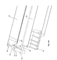
- the second engagement means is shown in its open position, i.e. when there is no engagement with the screening body represented by its bottom-most slat or the first engagement means. Following activation of the locking and release mechanism on pushing the button 196, the hooks 192 are free to move to the position shown in Fig. 14b .
- the first engagement means 208 comprises a leaf spring 281 adapted to engage with the bottom member 271 of the sash.
- the leaf spring 281 may be arranged in such a manner that engagement is carried out automatically. However, disengagement is carried out by lifting the leaf spring 281 slightly, thus releasing the engagement between the sash bottom member 271 and the roller shutter 281.
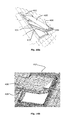
- Figs 16a and 16b two different screening arrangements are shown, which also make use of the first and second engagement means according to the invention and which are thus operated in a substantially corresponding manner, i.e. by operating the screening body by pivoting the sash of the window to a position in which the bottom member of the sash is located at or near the top member of the frame to enable engagement of the second engagement means with the first engagement means.
- Elements having the same or analogous function as in the embodiment of Figs 1 to 13 carry the same reference numerals to which 400 has been added. Only differences from that embodiment will be described in detail.
- the screening arrangement comprises a screening device in the form of an awning blind having a top element 402, which in the version shown in Fig.
- the first engagement means 408 connected to the awning blind may take the form of a bar or rod to engage with second engagement means 409, which for instance may take the form of the blocks shown in the embodiment of Figs 14a and 14b , or a leaf spring as in the embodiment of Fig. 15 . Further engagement means are of course conceivable, including magnets. Common to both versions of the awning blind is that this kind of screening device is not provided with side rails.
- first and second engagement means This makes it more difficult to obtain precise alignment of the first and second engagement means with respect to each other.
- the presence of second engagement means in the form of a bar to cooperate with the first engagement means having a relatively wide receiving opening allows for relatively large deviations in the alignment and still provides for secure engagement.
- the engagement and disengagement may be provided to be automatic, semi-automatic or manual.
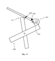
- the first and second sets of engagement means comprise magnets 308, 309 positioned at the top element of the roller shutter 301 and the bottom sash member 371, respectively.
- an operating member 350 to provide manual disengagement may be provided at the top element of the screening device 301.
- a handle may for instance be provided.
- engagement means providing the functionality aimed at are conceivable as well to provide the desired combination of automatic and manual engagement and disengagement, where engagement relates to coupling a first engagement means together with a second engagement means, and disengagement relates to decoupling first engagement means and second engagement means.
- FIG. 18 an alternative embodiment of the screening arrangement according to the invention will be described. Elements having the same or analogous function as in the embodiment of Figs 1 to 13 carry the same reference numerals preceded by the number 5. Only differences from that embodiment will be described in detail.
- the end profile 581 carries a sealing profile 555 to provide light-tightness when the roller shutter screening body is completely rolled out and abuts the cover 592 at the bottom of the sash.
- the hook 585 is provided with pivot pin 5851 and end 5853 to receive pin 5837 which protrudes through part circular groove 5836 in the back side of end piece 583 (cf. Fig. 20 ) to allow manual resetting or synchronization of the locking and release mechanism 586.
- the ratchet element 588 is provided with a guide portion 5883 to engage with the ball point element 587, thus fulfilling the function of guide portion 872 in the embodiment of Figs 1-13 .
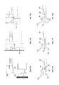
- Figs 30a to 30c The manual synchronization is shown in further detail in Figs 30a to 30c , showing a window with a screening arrangement 501 corresponding to the above embodiment of Figs 18 to 29 , with the screening body in a correct and an incorrect position with accompanying manual synchronization, respectively.
- Fig. 30a with its enlarged schematic views of the respective ends of the end profile of the screening arrangement 501, the pins 5837 are positioned correctly in the lower portion of groove 5836 in the right-hand and the left-hand sides (denoted by the marking "1" at the side of the groove 5836).
- Fig. 30a with its enlarged schematic views of the respective ends of the end profile of the screening arrangement 501, the pins 5837 are positioned correctly in the lower portion of groove 5836 in the right-hand and the left-hand sides (denoted by the marking "1" at the side of the groove 5836).
- Fig. 30a with its enlarged schematic views of the respective ends of the end profile
- the left-hand side pin 5837 is in its correct position of release (denoted by the marking "2" at the side of the groove 5836), whereas the right-hand side pin 5837 is still in its locking position at the end of the groove 5836.
- the right-hand side pin 5837 is moved in the direction indicated by arrow A towards the other end of the groove 5836.
- a marking "R” accompanied by an arrow may as shown be present at that end of the groove 5836 to indicate the reset or synchronization in a simple and logical manner.
- FIG. 19-20 and 28 One further detail of this alternative embodiment is seen in particular in Figs 19-20 and 28 , namely that a shoulder portion 5951 on the block 595, at the inclined portion 597, which is adapted to be accommodated in recess 5835 in end piece 583, when the block 595 with its hook portion 596 is moved past the final position of the end piece 583.
- This provides for a particularly secure engagement between the parts.
- roller shutter according to the invention has been described as being intended to be installed on the window frame of an openable roof window for installation in an inclined roof.
- the invention is applicable also with windows mounted in other positions, for instance on a window for installation in a building façade.
Landscapes
- Engineering & Computer Science (AREA)
- Structural Engineering (AREA)
- Architecture (AREA)
- Civil Engineering (AREA)
- Wing Frames And Configurations (AREA)
- Threshing Machine Elements (AREA)
- Specific Sealing Or Ventilating Devices For Doors And Windows (AREA)
Abstract
Description
- The present invention relates to a window comprising a frame and a sash, each having a top member, a bottom member and two side members, said sash being pivotally connected to the frame substantially at a centre axis, and a screening arrangement including a screening device with a top element mounted at the top member of the frame, two side rails, and a screening body, said screening body being adapted to be brought from a non-screening to a screening position from the top element, and at least one set of engagement means to provide operation of the screening arrangement, said set of engagement means including a first engagement means connected to the screening arrangement and a second engagement means. The invention furthermore relates to a screening arrangement, and to a method for operating a screening arrangement.
- Such screening arrangements including screening devices in the form of roller shutters are traditionally used for screening an aperture of a building structure, most often the light-admitting aperture of windows, but also of doors and other building openings. The roller shutters are either installed to extend substantially vertically in a building façade, or in an obliquely positioned roof window installed in an inclined roof surface, or as a horizontally extending cover for openings in a horizontal surface. When not screening the aperture, the screening body is normally rolled up on a roller bar accommodated in the top element of the roller shutter. The rolling up of the screening body may be effected either by a spring bias in the roller bar or by a drive motor. The unrolling of vertically situated roller shutters is normally effected in that the screening body moves by means of the gravity in the direction of the bottom of the aperture during simultaneous successive unrolling of the slats from the roller bar, and in roller shutters installed in for instance roof windows in an inclined roof, the unrolling normally takes place by means of drive devices.
- Manual unrolling and rolling-up of the screening body in roller shutters has been treated extensively in the prior art, and most solutions are often quite complex and require a rather extensive cord arrangement which may be a considerable drawback due to the limited place on the site of incorporation which is the case with e.g. roller shutters and other screening devices used in connection with roof windows. Furthermore, the positioning of the drive mechanism and its operating device is not always compatible with a need for a compact design of the roller shutter, and may furthermore require a particular design of the screening body and other parts.
- Several suggestions to solve this problem have been made, including examples known from
DE 20 2007 011 166 U1 ,EP 0 145 628 ,EP 0 317 461 andDE 40 00 908WO 98/19038 WO 2009/143853 which provide well-functioning driving devices but which are still relatively complex. - With this background it is an object to provide a window with a screening device having a simplified structure and which is more easily operated as compared to prior art screening devices.
- In a first aspect, this and further objects are met by a window of the kind mentioned in the introduction, which is furthermore characterized in that said second engagement means is provided at the bottom member of the sash, and that operation of the screening body between the non-screening and the screening position is carried out by pivoting the sash to enable engagement of the second engagement means with the first engagement means.
- In this manner, a new approach has been taken to designing and operating of the screening device. By providing the second engagement means at the bottom member of the sash so that the second engagement means moves with sash, a very straightforward operation of the screening device has been made possible, as operation is simply carried out by pivoting the sash in a normal opening movement through an angle bringing the bottom sash member to a position at or near the top frame member to enable engagement of the second engagement means with the first engagement means as the sash bottom member is located at or near the frame top member and hence the top element of the screening device. Following the mutual engagement, the sash is pivoted back in the closing direction, thus bringing the screening body from a non-screening to a screening position. Hence, when the screening body is in a screening position either fully or partly screening an opening of the window, the first engagement means and the second engagement means are coupled so that the sash may be used as an operating means for operating the screening body of the screening arrangement. This is generally achieved by positioning the second engagement means on the lower portion of the sash where the bottom member is positioned, e.g. on the bottom member of the sash or on a side member of the sash.
- Depending on the position of the centre axis of the frame around which the sash with the second engagement means rotates, the position of the first engagement means on the screening device is adjusted, so that when the sash with the second engagement means is pivoted the desired engagement between the first and second engagement means may be achieved.
- The engagement and disengagement may be carried out manually or automatically.
- In a presently preferred embodiment, the engagement of the second engagement means with the first engagement means is adapted to be carried out automatically. By "automatic" in the present context is to be understood that the engagement occurs as a result of the movement of the sash relative to the frame, i.e. coupling of the first and second engagement means is established at the final stage of pivoting the sash in which the sash bottom member is brought to a position at or near with the frame top member without a user operating the set of engagement means. The sash bottom member and frame top member should be moved into such into close proximity that the first engagement means may engage the second engagement means.
- In an embodiment, in which the engagement is carried out manually, the sash is operated to a position where the bottom member of the sash is located at or near the frame top member and hence the top element of the screening device, and the set of engagement means is manually engaged by the user of the window. When the engagement is carried out manually the user of the window must manually engage the engagement means e.g. by manually engaging the engagement means or by unfixing the screening body from the top element so that it may be moved to the screening position.
- In a further presently preferred embodiment, the disengagement of the second engagement means from the first engagement means is adapted to be carried out automatically. As for the term "automatic" in the context of disengagement, it is to be understood that the disengagement occurs as a result of the movement of the sash relative to the frame, i.e. decoupling of the first and second engagement means is established at the final stage of pivoting the sash in which the sash bottom member is brought to a position at or near with the frame top member without a user operating the set of engagement means.
- In general, the term "automatic" should in the present context also be interpreted as encompassing any operations not requiring the direct intervention of a user to occur. Other such automatic or semi-automatic operations include embodiments, in which for instance the sash is moved further in the pivoting movement relative to the frame during disengagement than during engagement, and the possibility of manual synchronization of the set of engagement means.
- When the disengagement is carried out manually the user of the window must manually disengage the engagement means e.g. by manually disengaging the engagement means or by fixing the screening body to the top element.
- In a combination of the presently preferred embodiments, i.e. when the engagement and the disengagement are carried out automatically, the sash is operated to a position where the bottom member of the sash is located at or near the frame top member and hence the top element of the screening device. If the sash returns to this position with the screening body from a screening position, the screening body is returned to the non-screening position in the top element and the set of engagement means is configured to disengage when the screening body has reached the non-screening position. If the screening body is in the non-screening position and the sash is moved to the position where the bottom member of the sash is located at or near the frame top member and hence the top element of the screening device, the set of engagement means is configured to engage so that when the sash is returned to a closed position the screening body is brought from the non-screening position to the screening position.
- Embodiments combining automatic or manual engagement and automatic or manual engagement is conceivable as well.
- In a preferred embodiment the first engagement means comprises at least one hook and a locking and release mechanism, and the second engagement means comprises at least one block including a hook portion and an inclined portion. This allows for a very stable engagement between the first and second engagement means and thereby a stable operation of the screening body between the screening position and the non-screening position and vice versa. Moreover, this configuration of the first and second engagement means allows an automatic engagement and disengagement of said first and second engagement means due to the locking and release mechanism and the inclined portion. When engaged the hook portions of the first and second engagement means are connected so that the screening body may be pushed to or pulled from the top element.
- In a further development of this embodiment that provides for an even more stable operation, the first engagement means comprises a longitudinally extending profile and an end piece at each end of the profile, one hook being connected to a respective end piece.
- In a further development of this embodiment, the second engagement means comprises a longitudinally extending bar and a mounting fitting at each end of the bar, one block being connected to a respective mounting fitting, preferably via a shaft portion. This mounting fitting allows for a stable connection between the second engagement means and the bottom member of the sash.
- In an even further developed embodiment, the block is guided in one of said side rails. This ensures that when the bottom member of the sash is moved to an open position wherein it is located at or near the frame top member and hence the top element of the screening device, the block is guided to a position allowing the second engagement means to engage with the first engagement means.
- In a further embodiment that allows for more stable movement of the block and thereby a more stable operation of the screening body between the screening and the non-screening position, the side rail comprises a set of guide profiles, and wherein the block is connected to the mounting fitting via a shaft portion, the shaft portion being guided between the guide profiles.
- In an alternative embodiment the first engagement means comprises at least one shaft portion and the second engagement means comprises at least one block including at least one hook and a locking and release mechanism.
- In a further practically simple embodiment the first engagement means comprises at least one leaf spring adapted to engage with the bottom member of the sash. This allows for automatic engagement and manual disengagement of the first and second engagement means.
- In a further practically simple embodiment, which also is preferred for automatic engagement and manual or automatic disengagement, at least one of the first engagement means and second engagement means comprises a magnet.
- In a second aspect, a screening arrangement is provided for use in such a window, the screening arrangement comprising a screening device with a top element adapted to be mounted at the top member of the frame, two side rails, and a screening body, said screening body being adapted to be rolled up on and unrolled from the top element, the top element of the screening device is adapted to be mounted at the top member of the frame, and at least one set of engagement means to provide operation of the screening device, said set of engagement means include a first engagement means connected to the screening device and a second engagement means, the screening arrangement being characterized in that said second engagement means is adapted to be provided at the bottom member of the sash, and that, in a condition of use, operation of the screening body between the non-screening and the screening position is carried out by pivoting the sash to a position in which the bottom member of the sash is located at or near the top member of the frame to enable engagement of the second engagement means with the first engagement means.
- In a third aspect is provided a method for operating a screening arrangement of a window, which comprises a frame and a sash, each with a top member, a bottom member and two side members, of which the sash is pivotally to the frame substantially at a centre axis, said method comprising the steps of: providing a screening device with a top element, two side rails, a screening body, and first engagement means, said screening body being adapted to be brought from a non-screening to a screening position, mounting the top element of the screening device at the top member of the frame, providing second engagement means at the bottom member of the sash, pivoting the sash in an opening direction about substantially the centre axis to bring the bottom member to a position at or near the top element of the screening device at top member of the frame, engaging the second engagement means with the first engagement means, and pivoting the sash in a closing direction thereby bringing the screening body from the top element.
- The advantages of the second and third aspects of the invention and further developed embodiments also applicable to the second and third aspects of the invention have been explained in the above description, and reference is made thereto.
- In further aspects, a window is provided comprising a frame and a sash, each having a top member, a bottom member and two side members, said sash being pivotally connected to the frame substantially at a centre axis, and a screening arrangement including a screening device with a top element mounted at the top member of the frame, and a screening body, said screening body being adapted to be brought from a non-screening to a screening position from the top element, the top element of the screening device being mounted at the top member of the frame, and at least one set of engagement means to provide operation of the screening arrangement, said set of engagement means including a first engagement means connected to the screening arrangement and a second engagement means. This further aspect is characterized in that said second engagement means is provided at the bottom member of the sash, and that operation of the screening body between the non-screening and the screening position is carried out by pivoting the sash to enable engagement of the second engagement means with the first engagement means, and the engagement of the second engagement means with the first engagement means is adapted to be carried out automatically.
- In preferred embodiment disengagement of the second engagement means from the first engagement means is adapted to be carried out automatically.
- In further embodiment disengagement of the second engagement means from the first engagement means is adapted to be carried out manually.
- In a further embodiment the first engagement means comprises a leaf spring adapted to engage with the bottom member of the sash.
- In a further embodiment the first and second engagement means comprise magnets.
- Further to that aspect a screening arrangement for use in the proceeding aspect is provided comprising a screening device with a top element adapted to be mounted at the top member of the frame, and a screening body, said screening body being adapted to be brought from a non-screening to a screening position from the top element, the top element of the screening device is adapted to be mounted at the top member of the frame, and a set of engagement means to provide operation of the screening device, said set of engagement means including a first engagement means connected to the screening device and a second engagement means. This further aspect is characterized in that second engagement means is adapted to be provided at the bottom member of the sash, and that, in a condition of use, operation of the screening body between the non-screening and the screening position is carried out by pivoting the sash to enable engagement of the second engagement means with the first engagement means, and the engagement of the second engagement means with the first engagement means is adapted to be carried out automatically.
- Even further to the two preceding aspects a method for operating a screening arrangement of a window is provided, which window comprises a frame and a sash, each with a top member, a bottom member and two side members, of which the sash is pivotally to the frame substantially at a centre axis, said method comprising the steps of: providing a screening device with a top element, a screening body, and first engagement means, said screening body being adapted to be brought from a non-screening to a screening position, mounting the top element of the screening device at the top member of the frame, providing second engagement means at the bottom member of the sash, pivoting the sash in an opening direction about substantially the centre axis to bring the bottom member to a position at or near the top element of the screening device at top member of the frame, engaging the second engagement means with the first engagement means, and pivoting the sash in a closing direction thereby bringing the screening body from the top element.
- Further details are described, and further advantages stated, in the description of particular embodiments of the invention.
- In the following the invention will be described in further detail by means of examples of embodiments with reference to the schematic drawings, in which
-
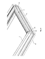
Fig. 1 is an isometric view of a window comprising a screening arrangement including a screening device and engagement means in an embodiment of the invention and in a closed position of the window; -
Fig. 2 is a partial isometric view, on a larger scale, of the window ofFig. 1 ; -
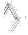
Fig. 3a shows a view corresponding toFig. 2 , with parts of the screening device removed; -
Fig. 3b shows a view corresponding substantially toFig. 2 , with parts of the screening device removed; -
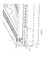
Fig. 4 shows, on a still larger scale, a partial view of the window shown inFig. 1 , with parts of the screening device removed; -
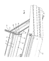
Fig. 5 is another partial view of the window shown inFig. 2 ; -
Fig. 6 is an isometric view of a screening arrangement in an embodiment of the invention; -
Fig. 7 is an isometric view of a window comprising a screening arrangement including a screening device and engagement means in an embodiment of the invention and in an open position of the window, in which engagement of the engagement means is enabled and the screening device is activated; -
Fig. 8 is a partial perspective view, on a larger scale, of the window shown inFig. 7 , with parts of the screening device removed; -
Fig. 9 shows, on a still larger scale, a partial perspective view of the window shown inFig. 7 , with parts of the screening device removed; -
Fig. 10 is an isometric view of a window comprising a screening arrangement including a screening device and engagement means in an embodiment of the invention and in a partially open position of the window, in which engagement of the engagement means is enabled and the screening device is activated; -
Fig. 11 is a partial perspective view, on a larger scale, of the window shown inFig. 10 , with parts of the screening device removed; -
Figs 12a and12b are partial perspective views of two different positions of the engagement means of a screening arrangement an embodiment of the invention; -
Figs 13a to 13g are views showing the positions of the first and second sets of engagement means in different situations; -
Figs 14a and 14b are schematic partial perspective views showing a detail of the window and the screening arrangement in another embodiment of the invention; -
Fig. 15 is a schematic partial perspective view showing a detail of the window and the screening arrangement in a further embodiment of the invention; -
Figs 16a and 16b are perspective views of alternative embodiments of a screening arrangement according to the invention; -
Fig. 17 is a schematic side view showing the window and the screening arrangement in a still further embodiment of the invention; -
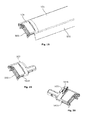
Figs 18 to 29 show views of a still further alternative embodiment; and -
Figs 30a to 30c show schematic overviews of details of a window with a screening arrangement in an embodiment of the invention with the screening body in a correct and an incorrect position with accompanying manual synchronization, respectively. -
Figs 1 to 13 show a first embodiment of a window comprising a screening arrangement comprising a screening device, which in the embodiment shown is a roller shutter generally designated 1. Theroller shutter 1 has atop element 2 and twoside rails top element 2. Ascreening body 5 includes a plurality ofslats 51 in the embodiment shown. Screening bodies having different configurations, such as a cloth, are conceivable. - The
roller shutter 1 is mounted on a window, for instance a roof window adapted for installation in an inclined roof. The window comprises in a manner known per se awindow frame 6 and awindow sash 7 encasing a pane (not shown). Theframe 6 and thesash 7 each has atop member 62, 72, abottom member side members window sash 7 is openable relative to thewindow frame 6, viz. hinge connected to thewindow frame 6 by means of a set of pivot hinges 65 positioned close to a centre axis of the window, i.e. at substantially a position approximately halfway between the top and bottom members of the sash and the frame, to allow thewindow sash 7 to pivot relative to thewindow frame 6. This makes it possible to operate the sash to a position where the bottom member of the sash is located at or near the frame top member and hence the top element of the screening device. - The aperture to be screened is defined by the area limited by the
top element 2, the side rails 3, 4, and the bottom of the window. This aperture thus corresponds in substance to the pane (not shown). In order to attain the desired screening, thescreening body 5 is adapted to be moved from a non-screening position to a screening position, in which it covers the pane and other parts of the window to a larger or lesser degree. Eachslat 51 extends in a longitudinal direction between two end edges and has first and second side edges parallel to the longitudinal direction, i.e. in parallel with thetop element 2. - In the embodiment shown, the
screening body 5 is adapted to be wound up in and rolled out from thetop element 2 in a direction perpendicular to said longitudinal direction to a desired screening position. Other manners of bringing the screening body from a non-screening to a screening position and vice versa are of course conceivable, including un-stacking and stacking, unfolding and folding the screening body, such as a screening body with a plurality of slats connected along the longitudinal direction or at their end portions. - In the position shown in
Fig. 1 , thescreening body 5 is entirely accommodated in thetop element 2 of theroller shutter 1. - The
top element 2 is positioned at the top of the window and comprises in the embodiment shown atop cover 21 and two outer end covers, of which the left-hand end cover 22 is visible inFig. 1 . As will be described in further detail below, thetop cover 21 and outer end covers 22 serve to hide and protect the inner parts of theroller shutter 1. Terms such as "left-hand" and "right-hand" refer to the orientation shown in for instanceFig. 1 and are utilized for reasons of convenience only. - The side rails 3, 4 each has a structure extending substantially throughout the height of the window and are rigidly connected to the
top element 2. At the opposite end, eachside rail bottom cover roller shutter 1, namely by across bar 35 connected to thebottom cover 40 ofside rail 4 and its counterpart bottom cover 30 ofside rail 3. Thecross bar 35 may for instance be connected to eachbottom cover cross bar 35, which track extends in the longitudinal direction of thecross bar 35. Thecross bar 35 provides a rectangular shape of the screening device and contributes to the strength and as well as resistance of the screening device. The position of thecross bar 35 betweenside rails Fig. 7 . - In the following, a particularly advantageous embodiment of the engagement means to provide operation of the roller shutter will be described in further detail. In this embodiment the set of engagement means include a first engagement means 8 connected to the
roller shutter 1 and a second engagement means 9 provided on thebottom member 71 of the sash. Operation of theroller shutter 1 to be carried out by pivoting the sash to enable engagement of the second engagement means 9 with the first engagement means 8 will also be described further on. - The engagement of the second engagement means 9 with the first engagement means 8 may either be carried out automatically or manually, just as disengagement of the second engagement means 9 from the first engagement means 8 may be carried out automatically or manually.
- By "automatic" in the present context is to be understood that the engagement occurs as a result of the movement of the
sash 7 relative to theframe 6, i.e. coupling of the first and second engagement means 8, 9 is established at the final stage of pivoting thesash 7 in which thesash 7bottom member frame top member 62, 72 without a user operating the set of engagement means. Thesash bottom member top member 62, 72 should be moved into such close proximity that the first engagement means 8 may engage the second engagement means 9. In general, the term "automatic" should in the present context also be interpreted as encompassing any operations not requiring the direct intervention of a user to occur. Other such automatic semi-automatic operations includes embodiments, in which for instance thesash 7 is moved further in the pivoting movement relative to theframe 6 during disengagement than during engagement, and the possibility of manual synchronization of the set of engagement means. - In the preferred embodiment, the first engagement means 8 comprises at least one
hook 85 and a locking andrelease mechanism 86. The second engagement means 9 comprises at least oneblock 95 including ahook portion 96 and aninclined portion 97. - In order to provide a mechanically stable and manageable structure, the first engagement means 8 comprises a
longitudinally extending profile 81, for instance formed as an end slat of thescreening body 5 and anend piece 83 at each end of theprofile 81, onehook 85 being connected to arespective end piece 83 in the embodiment shown, cf. in particularFig. 5 . - Referring in particular to
Figs 2-4 , the second engagement means 9 comprises a set ofblocks 95 connected to a mountingfitting block 95 is connected to mountingfittings shaft portion 98 so that theblock 95 is rotatably connected to the respective mounting fitting 93, 94. The mountingfittings sash 7 at thebottom member 71 thereof, possibly also to the lower portions of thesash side members cover 92, which has been removed for the sake of clarity inFig. 3b . - In the embodiment shown, each
block 95 is guided in a track formed in therespective side rail blocks 95 slide in the side rails 3, 4 when the sash is moved between a closed position and an open position. The engagement means are thus at all times protected by the respective side rail. To this end, eachside rail hand side rail 3. As eachblock 95 in the embodiment shown is rotatably connected to the respective mounting fitting 93, 94 via theshaft portion 98, theshaft portion 98 is guided between the guide profiles 31, 32. The track formed in the side rails, hereside rail 3, is shown in the perspective view ofFig. 3b , in which bottom cover 30 has been removed. When thesash 7 is moved to an open position and thesash 7 is moved towards thetop member 62, 72 of the frame, theshaft portion 98 extends between the side rails 3, 4 along which eachblock 95 is guided. In the embodiment shown, theblocks 95 in eachside rail respective hook portions 96 face each other. - Operation of the
roller shutter 1 is carried out by bringing thesash 7 from the position shown inFig. 1 to the position shown inFig. 7 , in which engagement between the first engagement means 8 and the second engagement means 9 is enabled. The engagement itself will be described with particular reference toFigs 9 and12a-12b , andFigs 13a-13g . - Following the engagement, the
screening body 5 is unrolled from thetop element 2 following the pivoting movement of thesash 7 to attain the desired screening position, for instance to the position shown inFig. 10 . Generally, thescreening body 5 is pulled from thetop element 2 towards a screening position by thesash 7. Likewise, thesash 7 may push thescreening body 5 towards the storage position, which may be facilitated by e.g. a spring-bias acting on thescreening body 5. In order to facilitate operation of the window and the screening device, thescreening body 5 may, when comprising a plurality ofslats 51, be configured with a light aperture allowing a small amount of light to enter between theslats 51 when thescreening body 5 is positioned in the screening position. Preferably, the light aperture is provided between the slats when the screening body is moved to towards the screening position, and when the slats are moved slightly towards the storage position by movement of the sash towards an open position, the light aperture between the slats is eliminated. - Referring now to the detailed
Figs 9 and12a-12b and13a-13g , it is initially noted that the principle underlying the function of the first engagement means 8 corresponds to that of for instance a ball point pen. Activation of the locking mechanism is carried out by pushing a button-like structure to bring a ball point-like structure from one position to another and the locking mechanism may be disengaged to allow the ball point to retract by pushing a button or lever mounted externally on the pen. - In a corresponding manner, the
hook 85 of the first engagement means 8 is able to assume two stable positions, namely a first position in which thehook 85 is held in a position in which it protrudes from theend piece 83 to allow engagement between the first and second engagement means 8, 9, and a second position in which thehook 85 is held close to theend piece 83 and the first and second engagement means 8, 9 are not engageable. Furthermore, thehook 85 may be biased in a direction away from theprofile 81 and theend piece 83. - In the first position of the
hook 85, engagement with thehook portion 96 of the second engagement means 9 is ensured. The engagement entails that the locking andrelease mechanism 86 assumes its locked position. Thescreening body 5 will thus follow the movement of thesash 7 during pivoting to assume a screening position, for instance the one shown inFig. 10 with details shown inFig. 11 . When pivoting thesash 7 back again towards an open position, thebottom member 71 of thesash 7 is again brought to a position near thetop member 62 of the sash and hence thetop element 2 of theroller shutter 1. Disengagement of the mutual engagement between the first and second sets of engagement means 8, 9 now takes place in the following manner: At the end of the movement of theroller shutter 1, for instance when theentire screening body 5 has been rolled up on the roller bar, the first engagement means 8 has reached the end of its travel. The position of thehook 85 is now fixed in the longitudinal direction of the side of the window. Thesash 7 may, however, be pivoted slightly further, and theinclined portion 96 of theblock 95 now pushes thehook 85 to the right, in the direction of theprofile 81, thus releasing the locking andrelease mechanism 86 and allows thehook 85 to return to its second position close to theend piece 83. This position corresponds to the activated position of the ball point pen analogy. Modifications of this embodiment are conceivable and are apparent to the person skilled in the art. - Referring now to the exploded view of
Fig. 13a , the parts which in the mounted position are located wholly or partially in theend piece 83 are shown. The locking andrelease mechanism 86 to bring thehook 85 from the first to the second position and vice versa thus comprises aball point element 87, aratchet element 88, aspring holder 82 and aspring 84, and ahead element 89. In theend piece 83, aspring 80 is furthermore accommodated to provide a spring bias to thehook 85. Thehook 85 is pivotally connected to theend piece 83 at apivot point 851 atconnection point 831 of theend piece 83. Theend piece 83 furthermore comprises abearing surface 832 for receiving theball point element 87 in slidable contact. Ahollow portion 833 of theend piece 83 serves partly as an engagement section to theprofile 81, partly for receivinghead element 89. - The
ball point element 87 comprises anengagement portion 871 facing thehook 85, anopposite guide portion 872 to be accommodated in theratchet element 88, a number ofcircumferential cams 873 and a number ofprotrusions 874, here four, for cooperation with corresponding tracks on the inner side of theend piece 83. Theratchet element 88 comprises a number of ribs, here four, withinclined end portions 881 to engage with thecams 873 of theball point element 87. At the opposite end, theratchet element 88 has anabutment face 882 facing thespring holder 82. In the assembled state, thespring 84 is compressed and accommodated in thehead element 89. Thehead element 89 is furthermore provided with twotongues 891 received in correspondingapertures 834 in theend piece 83 such that thehead element 89 is held stationary with respect to thehollow portion 833 of theend piece 83. - In the assembled state, the parts of the locking and
release mechanism 86 are movable with respect to each other to allow thehook 85 to assume the first and second positions, respectively. Theball point element 87 is slidably guided in theend piece 83 by means of the bearingsurface 832 and the tracks (not shown) inside theend piece 83 for receiving theprotrusions 874. When theball point element 87 is moved in the direction towards thehead element 89, thecams 873 interact with theinclined end portions 881 of theratchet element 88 which in turn effects thespring holder 82 viaabutment face 882. Theratchet element 88 is moved against the spring bias from thespring 84 accommodated on thespring holder 82 and a rotating motion is obtained, which effects a shift in the engagement between thecams 873 and theinclined end portions 881, and in turn, this moves theball point element 87 from a position in which theball point element 87 is retracted, i.e. corresponding to the first position of thehook 85, to a protruding position of theball point element 87, i.e. the second position of thehook 85, and vice versa. - The positions of the parts of the locking and
release mechanism 86 are best understood in reference toFigs 13b-13d in conjunction with the respectiveFigs 13e-13g . - In
Fig. 13b , thehook 85 is in its second position close to theend piece 83, and no engagement with theblock 95 is possible. Theball point element 87 is located close to theratchet element 88 as shown inFig. 13e . This situation has been reached when manually synchronizing the engagement means, in the shown embodiment by handling a pin in theend piece 83 corresponding to thepin 5837 of the embodiment shown inFigs 18 to 29 . This may be particularly relevant if engagement means are provided at either side of the window. In this case, it may occur that the engagement means 8 at one side is ready for engagement, and the corresponding engagement means at the other side is not. Manual synchronization will then be necessary to bring the engagement means to the same positions. InFig. 13c , thehook 85 is ready for engagement and will engage with theblock 95 if thewindow sash 7 is pivoted further. Manual synchronization is shown in further detail inFigs 30a to 30c , showing a window with a screening arrangement in an embodiment of the invention with the screening body in a correct and an incorrect position with accompanying manual synchronization, respectively. - The activation of the locking and
release mechanism 86 to pivot thehook 95 about itspivot point 851 may take place by pushing theball point element 87 in the direction of thehead element 89 by pressing thehook 85 itself manually, or semi-automatically, by the interaction between theinclined surface 96 of theblock 95 when moving theblock 95 past the end position of theprofile 81 and theend piece 83 as described in the above. - Alternatively, in embodiments where the
end piece 83 at each end of theprofile 81 comprises first engagement means e.g. ahook 85, the springbiased hook 85 may obtain a first position as shown inFig. 12a , where the first engagement means and the second engagement means are coupled together, and a second position as shown inFig. 12b where the first engagement means and the second engagement means are decoupled. In such embodiments it is preferred that thehook 85 pivotally connected to theend piece 83 and further to theprofile 81 by means of apivot point 851 comprises afurther portion 852 extending inside theend piece 83, preferably extending from thepivot point 851. From anend 853 of the further portion 852 a pin (not shown in this embodiment) extends into a part circular groove in the rear side of theend piece 83, i.e. the opposite side of that shown inFigs. 12a and12b . This allows the user of the screening device to manipulate the position of thehook 85 by operating the pin extending in the part circular groove. This will be described in further detail below with particular reference toFigs 18 to 30 . - Following activation, the
ball point element 87 is forced outwards away from thehead element 89, and thehook 85 is pivoted about itspivot point 851 to attain the position shown inFigs 13c and 13d . From the position shown inFig. 13d , the screening device may be operated in pivoting the sash towards its closed position and back again. In case screening is no longer desired, the engagement between the first and second engagement means is released as described in the above to attain the position shown inFig. 13b allowing the window sash to pivot without simultaneously unrolling the screening body. - In the further embodiment shown in
Figs 14a and 14b elements having the same or analogous function as corresponding elements of the first embodiment shown inFigs 1 to 11 carry the same reference numerals to which 100 has been added. In an embodiment according toFigs 14a and 14b , the first engagement means comprises at least one shaft portion (not shown) and the second engagement means comprises at least oneblock 195 including in the embodiment shown twohooks 192 and a locking and release mechanism not shown in detail. InFig. 14 , the second engagement means is shown in its open position, i.e. when there is no engagement with the screening body represented by its bottom-most slat or the first engagement means. Following activation of the locking and release mechanism on pushing thebutton 196, thehooks 192 are free to move to the position shown inFig. 14b . - In the alternative embodiment of
Fig. 15 , in which elements having the same or analogous function as corresponding elements of the first embodiment shown inFigs 1 to 11 carry the same reference numerals to which 200 has been added, the first engagement means 208 comprises aleaf spring 281 adapted to engage with thebottom member 271 of the sash. Theleaf spring 281 may be arranged in such a manner that engagement is carried out automatically. However, disengagement is carried out by lifting theleaf spring 281 slightly, thus releasing the engagement between thesash bottom member 271 and theroller shutter 281. - In
Figs 16a and 16b , two different screening arrangements are shown, which also make use of the first and second engagement means according to the invention and which are thus operated in a substantially corresponding manner, i.e. by operating the screening body by pivoting the sash of the window to a position in which the bottom member of the sash is located at or near the top member of the frame to enable engagement of the second engagement means with the first engagement means. Elements having the same or analogous function as in the embodiment ofFigs 1 to 13 carry the same reference numerals to which 400 has been added. Only differences from that embodiment will be described in detail. In these Figures, the screening arrangement comprises a screening device in the form of an awning blind having atop element 402, which in the version shown inFig. 16a is positioned in the same plane as or below a corresponding top element of the window frame, and which in the version shown inFig. 16b is located on top of the top element of the window frame. From thetop element 402, ascreening body 405 in the form of screening cloth or screen is able to be pulled out when activating the screening device. The first engagement means 408 connected to the awning blind may take the form of a bar or rod to engage with second engagement means 409, which for instance may take the form of the blocks shown in the embodiment ofFigs 14a and 14b , or a leaf spring as in the embodiment ofFig. 15 . Further engagement means are of course conceivable, including magnets. Common to both versions of the awning blind is that this kind of screening device is not provided with side rails. This makes it more difficult to obtain precise alignment of the first and second engagement means with respect to each other. The presence of second engagement means in the form of a bar to cooperate with the first engagement means having a relatively wide receiving opening allows for relatively large deviations in the alignment and still provides for secure engagement. Also in this kind of screening arrangement, the engagement and disengagement may be provided to be automatic, semi-automatic or manual. - Referring now to the schematic side view of
Fig. 17 showing a still further embodiment, in which elements having the same or analogous function as corresponding elements of the first embodiment shown inFigs 1 to 11 carry the same reference numerals to which 300 has been added. In this embodiment, the first and second sets of engagement means comprisemagnets roller shutter 301 and thebottom sash member 371, respectively. In this simple embodiment an operatingmember 350 to provide manual disengagement may be provided at the top element of thescreening device 301. In order to facilitate the disengagement of the magnetic attraction, a handle may for instance be provided. - Other engagement means providing the functionality aimed at are conceivable as well to provide the desired combination of automatic and manual engagement and disengagement, where engagement relates to coupling a first engagement means together with a second engagement means, and disengagement relates to decoupling first engagement means and second engagement means.
- Referring now to
Figs 18 to 29 , an alternative embodiment of the screening arrangement according to the invention will be described. Elements having the same or analogous function as in the embodiment ofFigs 1 to 13 carry the same reference numerals preceded by thenumber 5. Only differences from that embodiment will be described in detail. - In this embodiment, the
end profile 581 carries asealing profile 555 to provide light-tightness when the roller shutter screening body is completely rolled out and abuts thecover 592 at the bottom of the sash. Thehook 585 is provided withpivot pin 5851 andend 5853 to receivepin 5837 which protrudes through partcircular groove 5836 in the back side of end piece 583 (cf.Fig. 20 ) to allow manual resetting or synchronization of the locking andrelease mechanism 586. Furthermore, theratchet element 588 is provided with aguide portion 5883 to engage with theball point element 587, thus fulfilling the function ofguide portion 872 in the embodiment ofFigs 1-13 . - The manual synchronization is shown in further detail in
Figs 30a to 30c , showing a window with ascreening arrangement 501 corresponding to the above embodiment ofFigs 18 to 29 , with the screening body in a correct and an incorrect position with accompanying manual synchronization, respectively. As shown inFig. 30a with its enlarged schematic views of the respective ends of the end profile of thescreening arrangement 501, thepins 5837 are positioned correctly in the lower portion ofgroove 5836 in the right-hand and the left-hand sides (denoted by the marking "1" at the side of the groove 5836). Correspondingly, inFig. 30b , the left-hand side pin 5837 is in its correct position of release (denoted by the marking "2" at the side of the groove 5836), whereas the right-hand side pin 5837 is still in its locking position at the end of thegroove 5836. As indicated inFig. 30c , the right-hand side pin 5837 is moved in the direction indicated by arrow A towards the other end of thegroove 5836. A marking "R" accompanied by an arrow may as shown be present at that end of thegroove 5836 to indicate the reset or synchronization in a simple and logical manner. - Other parts of the locking and
release mechanism 586 function in substantially the same manner as has already been described, and the parts of the locking andrelease mechanism 586 are movable with respect to each other to allow thehook 585 to assume the first and second positions, respectively. When pushing theball point element 587 in the direction towards thehead element 589, thecams 5873 interact with theinclined end portions 5881 of theratchet element 588 which in turn effect thespring holder 582 viaabutment face 5882. Theratchet element 588 is moved against the spring bias from thespring 584 accommodated on thespring holder 582 and a rotating motion is obtained, which effects a shift from a position in which theball point element 587 is retracted, i.e. corresponding to the first position of thehook 585, to a protruding position of theball point element 587, i.e. the second position of the hook, and vice versa. - One further detail of this alternative embodiment is seen in particular in
Figs 19-20 and28 , namely that ashoulder portion 5951 on theblock 595, at theinclined portion 597, which is adapted to be accommodated inrecess 5835 inend piece 583, when theblock 595 with itshook portion 596 is moved past the final position of theend piece 583. This provides for a particularly secure engagement between the parts. - Eventually, the roller shutter according to the invention has been described as being intended to be installed on the window frame of an openable roof window for installation in an inclined roof. However, the invention is applicable also with windows mounted in other positions, for instance on a window for installation in a building façade.
- The invention should not be regarded as being limited to the described embodiments. Several modifications and combinations of the different embodiments will be apparent to the person skilled in the art.
Claims (15)
- A window comprising:a frame (6) and a sash (7), each having a top member (62, 72), a bottom member (61, 71) and two side members (63, 64, 73, 74), said sash being pivotally connected to the frame substantially at a centre axis, anda screening arrangement including a screening device (1) with a top element (2) mounted at the top member (62) of the frame, two side rails (3, 4), and a screening body (5), said screening body being adapted to be brought from a non-screening to a screening position from the top element, , and at least one set of engagement means to provide operation of the screening arrangement, said set of engagement means including a first engagement means (8) connected to the screening arrangement and a second engagement means (9),characterized in that said second engagement means (9) is provided at the bottom member (71) of the sash, and that operation of the screening body (5) between the non-screening and the screening position is carried out by pivoting the sash to a position in which the bottom member (71) of the sash is located at or near the top member (62) of the frame to enable engagement of the second engagement means (9) with the first engagement means (8).
- A window according to claim 1, wherein the engagement of the second engagement means (9) with the first engagement means (8) is adapted to be carried out automatically.
- A window according to claim 1, wherein the engagement of the second engagement means with the first engagement means is adapted to be carried out manually.
- A window according to claim 1 or 2, wherein disengagement of the second engagement means (9) from the first engagement means (8) is adapted to be carried out automatically.
- A window according to claim 1 or 2, wherein disengagement of the second engagement means from the first engagement means is adapted to be carried out manually.
- A window according to claims 2 and 4, wherein the first engagement means (8) comprises at least one hook (85) and a locking and release mechanism (86), and the second engagement means (9) comprises at least one block (95) including a hook portion (96) and an inclined portion (97).
- A window according to claim 6, wherein the first engagement means (8) comprises a longitudinally extending profile (81) and an end piece (83) at each end of the profile (81), one hook (85) being connected to a respective end piece.
- A window according to claim 6 or 7, wherein the second engagement means (9) comprises a set of blocks (95) connected to a mounting fitting (93, 94), preferably via a shaft portion (98).
- A window according to claim 8, wherein the block (95) is guided in one of said side rails (3, 4).
- A window according to claim 9, wherein the side rails (3, 4) comprises a set of guide profiles (31, 32), and wherein the block (95) is connected to the mounting fitting (93, 94) via a shaft portion (98), the shaft portion (98) being guided between the guide profiles (31, 32).
- A window according to claims 2 and 4, wherein the first engagement means comprises at least one shaft portion (180) and the second engagement means (190) comprises at least one block (191) including at least one hook (192) and a locking and release mechanism.
- A window according to claims 2 and 5, wherein the first engagement means (280) comprises at least one leaf spring (281) adapted to engage with the bottom member (71) of the sash.
- A window according to claim 2 and 4, wherein at least one of the first and second engagement means (380, 390) comprise a magnet.
- A screening arrangement for use in the window according to any one of the preceding claims, comprising a screening device (1) with a top element (2) adapted to be mounted at the top member (62) of the frame, two side rails (3, 4), and a screening body (5), said screening body being adapted to be brought from a non-screening to a screening position from the top element, the top element (2) of the screening device is adapted to be mounted at the top member (62) of the frame, and at least one set of engagement means to provide operation of the screening device, said set of engagement means including a first engagement means (8) connected to the screening device and a second engagement means (9),
characterized in that said second engagement means (9) is adapted to be provided at the bottom member (71) of the sash, and that, in a condition of use, operation of the screening body (5) between the non-screening and the screening position is carried out by pivoting the sash to a position in which the bottom member (71) of the sash is located at or near the top member (62) of the frame to enable engagement of the second engagement means (9) with the first engagement means (8). - A method for operating a screening arrangement of a window, which comprises a frame (6) and a sash (7), each with a top member (62, 72), a bottom member (61, 71) and two side members (63, 64, 73, 74), of which the sash is pivotally to the frame substantially at a centre axis, said method comprising the steps of:providing a screening device (1) with a top element (2), two side rails (3, 4), a screening body (5), and first engagement means (8), said screening body being adapted to be brought from a non-screening to a screening position,mounting the top element (2) of the screening device (1) at the top member (62) of the frame,providing second engagement means (9) at the bottom member (71) of the sash,pivoting the sash in an opening direction about substantially the centre axis to bring the bottom member (71) to a position at or near the top element (2) of the screening device (1) at top member (62) of the frame,engaging the second engagement means (9) with the first engagement means (8), andpivoting the sash in a closing direction thereby bringing the screening body (5) from the top element (2).
Applications Claiming Priority (2)
| Application Number | Priority Date | Filing Date | Title |
|---|---|---|---|
| DKPA201270376 | 2012-06-28 | ||
| DKPA201370065 | 2013-02-08 |
Publications (3)
| Publication Number | Publication Date |
|---|---|
| EP2679760A2 true EP2679760A2 (en) | 2014-01-01 |
| EP2679760A3 EP2679760A3 (en) | 2016-04-13 |
| EP2679760B1 EP2679760B1 (en) | 2020-03-25 |
Family
ID=48655997
Family Applications (1)
| Application Number | Title | Priority Date | Filing Date |
|---|---|---|---|
| EP13173331.3A Active EP2679760B1 (en) | 2012-06-28 | 2013-06-24 | A window with a screening arrangement, and a method for operating the screening arrangement |
Country Status (2)
| Country | Link |
|---|---|
| EP (1) | EP2679760B1 (en) |
| RU (1) | RU2013129567A (en) |
Cited By (3)
| Publication number | Priority date | Publication date | Assignee | Title |
|---|---|---|---|---|
| JP2017115314A (en) * | 2015-12-21 | 2017-06-29 | キマド株式会社 | Window shoji with roll blind |
| EP3859120A1 (en) * | 2020-02-03 | 2021-08-04 | VKR Holding A/S | A screening arrangement for a skylight window, a skylight window comprising such a screening arrangement, and a method of installing a screening arrangement in a skylight window |
| JP2026121532A (en) * | 2023-05-31 | 2026-07-24 | パナソニックハウジングソリューションズ株式会社 | Sash windows |
Families Citing this family (1)
| Publication number | Priority date | Publication date | Assignee | Title |
|---|---|---|---|---|
| PL447766A1 (en) * | 2024-02-14 | 2025-08-18 | Fakro Pp Spółka Z Ograniczoną Odpowiedzialnością | Building partition curtain hook set and building partition curtain with this set |
Family Cites Families (4)
| Publication number | Priority date | Publication date | Assignee | Title |
|---|---|---|---|---|
| BE551506A (en) * | 1955-10-04 | |||
| DK172413B1 (en) * | 1996-06-18 | 1998-05-25 | Rasmussen Kann Ind As | Exterior screen for a tiltable skylight |
| DE202005014984U1 (en) * | 2005-09-23 | 2006-02-02 | Lss Lewens Sonnenschutz-Systeme Gmbh & Co. Kg | Shading device for skylight has supporting framework having retaining profiles for attaching to upper end of framework |
| DE202007011166U1 (en) * | 2007-08-09 | 2007-10-25 | Arnold, Jürgen | Roller shutters for a skylight |
-
2013
- 2013-06-24 EP EP13173331.3A patent/EP2679760B1/en active Active
- 2013-06-27 RU RU2013129567/12A patent/RU2013129567A/en not_active Application Discontinuation
Cited By (3)
| Publication number | Priority date | Publication date | Assignee | Title |
|---|---|---|---|---|
| JP2017115314A (en) * | 2015-12-21 | 2017-06-29 | キマド株式会社 | Window shoji with roll blind |
| EP3859120A1 (en) * | 2020-02-03 | 2021-08-04 | VKR Holding A/S | A screening arrangement for a skylight window, a skylight window comprising such a screening arrangement, and a method of installing a screening arrangement in a skylight window |
| JP2026121532A (en) * | 2023-05-31 | 2026-07-24 | パナソニックハウジングソリューションズ株式会社 | Sash windows |
Also Published As
| Publication number | Publication date |
|---|---|
| EP2679760B1 (en) | 2020-03-25 |
| RU2013129567A (en) | 2015-01-10 |
| EP2679760A3 (en) | 2016-04-13 |
Similar Documents
| Publication | Publication Date | Title |
|---|---|---|
| EP2679760B1 (en) | A window with a screening arrangement, and a method for operating the screening arrangement | |
| TWI648460B (en) | Window shade and its spring drive system | |
| EP3760826B1 (en) | A screening device, a roof window comprising such a screening device and a method for mounting such a screening device on a roof window | |
| JP2010071043A (en) | Fittings | |
| JP2018090966A (en) | Fitting | |
| KR101066430B1 (en) | Window device with security function | |
| KR101597914B1 (en) | Locking Apparatus for a mosquito net | |
| TW202613400A (en) | Anchor device for an operating element and window shade including the same | |
| JP4875953B2 (en) | Opening device provided with opening and closing means | |
| KR101211761B1 (en) | Windows for project and casement having improved hinge parts | |
| JP4814850B2 (en) | Louver equipment and joinery | |
| EP2540929B1 (en) | Folding shutter | |
| US8549789B2 (en) | Hidden window retainer system for doors | |
| EP4390047B1 (en) | Screening arrangement comprising a suspension assembly, and a method of mounting the screening arrangement | |
| US20250176739A1 (en) | Child safety gate with barrier tensioning means | |
| JP4588475B2 (en) | Switchgear | |
| AU2011343291A1 (en) | Mechanism for rotating the slats of a roller shutter | |
| KR20130006936U (en) | A window of horizontality movable type to front and rear | |
| JP5502004B2 (en) | Open control device and joinery | |
| JP6727646B2 (en) | Pulling device for sliding window | |
| KR200473054Y1 (en) | Improved locking device for door | |
| JP4168396B2 (en) | Locking structure in shutter device | |
| JP4673683B2 (en) | Switchgear | |
| JP4578360B2 (en) | Joining prevention device and joinery provided with the same | |
| JP2000110469A (en) | Locking device for architectural shutter |
Legal Events
| Date | Code | Title | Description |
|---|---|---|---|
| PUAI | Public reference made under article 153(3) epc to a published international application that has entered the european phase |
Free format text: ORIGINAL CODE: 0009012 |
|
| AK | Designated contracting states |
Kind code of ref document: A2 Designated state(s): AL AT BE BG CH CY CZ DE DK EE ES FI FR GB GR HR HU IE IS IT LI LT LU LV MC MK MT NL NO PL PT RO RS SE SI SK SM TR |
|
| AX | Request for extension of the european patent |
Extension state: BA ME |
|
| PUAL | Search report despatched |
Free format text: ORIGINAL CODE: 0009013 |
|
| AK | Designated contracting states |
Kind code of ref document: A3 Designated state(s): AL AT BE BG CH CY CZ DE DK EE ES FI FR GB GR HR HU IE IS IT LI LT LU LV MC MK MT NL NO PL PT RO RS SE SI SK SM TR |
|
| AX | Request for extension of the european patent |
Extension state: BA ME |
|
| RIC1 | Information provided on ipc code assigned before grant |
Ipc: E06B 9/11 20060101AFI20160307BHEP Ipc: E06B 9/56 20060101ALN20160307BHEP Ipc: E06B 9/92 20060101ALN20160307BHEP |
|
| 17P | Request for examination filed |
Effective date: 20161013 |
|
| RBV | Designated contracting states (corrected) |
Designated state(s): AL AT BE BG CH CY CZ DE DK EE ES FI FR GB GR HR HU IE IS IT LI LT LU LV MC MK MT NL NO PL PT RO RS SE SI SK SM TR |
|
| STAA | Information on the status of an ep patent application or granted ep patent |
Free format text: STATUS: EXAMINATION IS IN PROGRESS |
|
| 17Q | First examination report despatched |
Effective date: 20170306 |
|
| GRAP | Despatch of communication of intention to grant a patent |
Free format text: ORIGINAL CODE: EPIDOSNIGR1 |
|
| STAA | Information on the status of an ep patent application or granted ep patent |
Free format text: STATUS: GRANT OF PATENT IS INTENDED |
|
| RIC1 | Information provided on ipc code assigned before grant |
Ipc: E06B 9/56 20060101ALN20191008BHEP Ipc: E06B 9/92 20060101ALN20191008BHEP Ipc: E06B 9/11 20060101AFI20191008BHEP |
|
| INTG | Intention to grant announced |
Effective date: 20191025 |
|
| GRAS | Grant fee paid |
Free format text: ORIGINAL CODE: EPIDOSNIGR3 |
|
| GRAA | (expected) grant |
Free format text: ORIGINAL CODE: 0009210 |
|
| STAA | Information on the status of an ep patent application or granted ep patent |
Free format text: STATUS: THE PATENT HAS BEEN GRANTED |
|
| AK | Designated contracting states |
Kind code of ref document: B1 Designated state(s): AL AT BE BG CH CY CZ DE DK EE ES FI FR GB GR HR HU IE IS IT LI LT LU LV MC MK MT NL NO PL PT RO RS SE SI SK SM TR |
|
| REG | Reference to a national code |
Ref country code: GB Ref legal event code: FG4D |
|
| REG | Reference to a national code |
Ref country code: DE Ref legal event code: R096 Ref document number: 602013067098 Country of ref document: DE |
|
| REG | Reference to a national code |
Ref country code: AT Ref legal event code: REF Ref document number: 1248759 Country of ref document: AT Kind code of ref document: T Effective date: 20200415 Ref country code: IE Ref legal event code: FG4D |
|
| REG | Reference to a national code |
Ref country code: NL Ref legal event code: FP |
|
| PG25 | Lapsed in a contracting state [announced via postgrant information from national office to epo] |
Ref country code: FI Free format text: LAPSE BECAUSE OF FAILURE TO SUBMIT A TRANSLATION OF THE DESCRIPTION OR TO PAY THE FEE WITHIN THE PRESCRIBED TIME-LIMIT Effective date: 20200325 Ref country code: NO Free format text: LAPSE BECAUSE OF FAILURE TO SUBMIT A TRANSLATION OF THE DESCRIPTION OR TO PAY THE FEE WITHIN THE PRESCRIBED TIME-LIMIT Effective date: 20200625 Ref country code: RS Free format text: LAPSE BECAUSE OF FAILURE TO SUBMIT A TRANSLATION OF THE DESCRIPTION OR TO PAY THE FEE WITHIN THE PRESCRIBED TIME-LIMIT Effective date: 20200325 |
|
| PG25 | Lapsed in a contracting state [announced via postgrant information from national office to epo] |
Ref country code: BG Free format text: LAPSE BECAUSE OF FAILURE TO SUBMIT A TRANSLATION OF THE DESCRIPTION OR TO PAY THE FEE WITHIN THE PRESCRIBED TIME-LIMIT Effective date: 20200625 Ref country code: GR Free format text: LAPSE BECAUSE OF FAILURE TO SUBMIT A TRANSLATION OF THE DESCRIPTION OR TO PAY THE FEE WITHIN THE PRESCRIBED TIME-LIMIT Effective date: 20200626 Ref country code: SE Free format text: LAPSE BECAUSE OF FAILURE TO SUBMIT A TRANSLATION OF THE DESCRIPTION OR TO PAY THE FEE WITHIN THE PRESCRIBED TIME-LIMIT Effective date: 20200325 Ref country code: LV Free format text: LAPSE BECAUSE OF FAILURE TO SUBMIT A TRANSLATION OF THE DESCRIPTION OR TO PAY THE FEE WITHIN THE PRESCRIBED TIME-LIMIT Effective date: 20200325 Ref country code: HR Free format text: LAPSE BECAUSE OF FAILURE TO SUBMIT A TRANSLATION OF THE DESCRIPTION OR TO PAY THE FEE WITHIN THE PRESCRIBED TIME-LIMIT Effective date: 20200325 |
|
| REG | Reference to a national code |
Ref country code: LT Ref legal event code: MG4D |
|
| PG25 | Lapsed in a contracting state [announced via postgrant information from national office to epo] |
Ref country code: PT Free format text: LAPSE BECAUSE OF FAILURE TO SUBMIT A TRANSLATION OF THE DESCRIPTION OR TO PAY THE FEE WITHIN THE PRESCRIBED TIME-LIMIT Effective date: 20200818 Ref country code: LT Free format text: LAPSE BECAUSE OF FAILURE TO SUBMIT A TRANSLATION OF THE DESCRIPTION OR TO PAY THE FEE WITHIN THE PRESCRIBED TIME-LIMIT Effective date: 20200325 Ref country code: CZ Free format text: LAPSE BECAUSE OF FAILURE TO SUBMIT A TRANSLATION OF THE DESCRIPTION OR TO PAY THE FEE WITHIN THE PRESCRIBED TIME-LIMIT Effective date: 20200325 Ref country code: IS Free format text: LAPSE BECAUSE OF FAILURE TO SUBMIT A TRANSLATION OF THE DESCRIPTION OR TO PAY THE FEE WITHIN THE PRESCRIBED TIME-LIMIT Effective date: 20200725 Ref country code: SK Free format text: LAPSE BECAUSE OF FAILURE TO SUBMIT A TRANSLATION OF THE DESCRIPTION OR TO PAY THE FEE WITHIN THE PRESCRIBED TIME-LIMIT Effective date: 20200325 Ref country code: RO Free format text: LAPSE BECAUSE OF FAILURE TO SUBMIT A TRANSLATION OF THE DESCRIPTION OR TO PAY THE FEE WITHIN THE PRESCRIBED TIME-LIMIT Effective date: 20200325 Ref country code: EE Free format text: LAPSE BECAUSE OF FAILURE TO SUBMIT A TRANSLATION OF THE DESCRIPTION OR TO PAY THE FEE WITHIN THE PRESCRIBED TIME-LIMIT Effective date: 20200325 Ref country code: SM Free format text: LAPSE BECAUSE OF FAILURE TO SUBMIT A TRANSLATION OF THE DESCRIPTION OR TO PAY THE FEE WITHIN THE PRESCRIBED TIME-LIMIT Effective date: 20200325 |
|
| REG | Reference to a national code |
Ref country code: AT Ref legal event code: MK05 Ref document number: 1248759 Country of ref document: AT Kind code of ref document: T Effective date: 20200325 |
|
| REG | Reference to a national code |
Ref country code: DE Ref legal event code: R097 Ref document number: 602013067098 Country of ref document: DE |
|
| PG25 | Lapsed in a contracting state [announced via postgrant information from national office to epo] |
Ref country code: IT Free format text: LAPSE BECAUSE OF FAILURE TO SUBMIT A TRANSLATION OF THE DESCRIPTION OR TO PAY THE FEE WITHIN THE PRESCRIBED TIME-LIMIT Effective date: 20200325 Ref country code: MC Free format text: LAPSE BECAUSE OF FAILURE TO SUBMIT A TRANSLATION OF THE DESCRIPTION OR TO PAY THE FEE WITHIN THE PRESCRIBED TIME-LIMIT Effective date: 20200325 Ref country code: DK Free format text: LAPSE BECAUSE OF FAILURE TO SUBMIT A TRANSLATION OF THE DESCRIPTION OR TO PAY THE FEE WITHIN THE PRESCRIBED TIME-LIMIT Effective date: 20200325 Ref country code: ES Free format text: LAPSE BECAUSE OF FAILURE TO SUBMIT A TRANSLATION OF THE DESCRIPTION OR TO PAY THE FEE WITHIN THE PRESCRIBED TIME-LIMIT Effective date: 20200325 Ref country code: AT Free format text: LAPSE BECAUSE OF FAILURE TO SUBMIT A TRANSLATION OF THE DESCRIPTION OR TO PAY THE FEE WITHIN THE PRESCRIBED TIME-LIMIT Effective date: 20200325 |
|
| REG | Reference to a national code |
Ref country code: CH Ref legal event code: PL |
|
| PLBE | No opposition filed within time limit |
Free format text: ORIGINAL CODE: 0009261 |
|
| STAA | Information on the status of an ep patent application or granted ep patent |
Free format text: STATUS: NO OPPOSITION FILED WITHIN TIME LIMIT |
|
| PG25 | Lapsed in a contracting state [announced via postgrant information from national office to epo] |
Ref country code: PL Free format text: LAPSE BECAUSE OF FAILURE TO SUBMIT A TRANSLATION OF THE DESCRIPTION OR TO PAY THE FEE WITHIN THE PRESCRIBED TIME-LIMIT Effective date: 20200325 |
|
| 26N | No opposition filed |
Effective date: 20210112 |
|
| GBPC | Gb: european patent ceased through non-payment of renewal fee |
Effective date: 20200625 |
|
| PG25 | Lapsed in a contracting state [announced via postgrant information from national office to epo] |
Ref country code: LU Free format text: LAPSE BECAUSE OF NON-PAYMENT OF DUE FEES Effective date: 20200624 |
|
| REG | Reference to a national code |
Ref country code: BE Ref legal event code: MM Effective date: 20200630 |
|
| PG25 | Lapsed in a contracting state [announced via postgrant information from national office to epo] |
Ref country code: CH Free format text: LAPSE BECAUSE OF NON-PAYMENT OF DUE FEES Effective date: 20200630 Ref country code: LI Free format text: LAPSE BECAUSE OF NON-PAYMENT OF DUE FEES Effective date: 20200630 Ref country code: IE Free format text: LAPSE BECAUSE OF NON-PAYMENT OF DUE FEES Effective date: 20200624 Ref country code: GB Free format text: LAPSE BECAUSE OF NON-PAYMENT OF DUE FEES Effective date: 20200625 |
|
| PG25 | Lapsed in a contracting state [announced via postgrant information from national office to epo] |
Ref country code: SI Free format text: LAPSE BECAUSE OF FAILURE TO SUBMIT A TRANSLATION OF THE DESCRIPTION OR TO PAY THE FEE WITHIN THE PRESCRIBED TIME-LIMIT Effective date: 20200325 Ref country code: BE Free format text: LAPSE BECAUSE OF NON-PAYMENT OF DUE FEES Effective date: 20200630 |
|
| PG25 | Lapsed in a contracting state [announced via postgrant information from national office to epo] |
Ref country code: TR Free format text: LAPSE BECAUSE OF FAILURE TO SUBMIT A TRANSLATION OF THE DESCRIPTION OR TO PAY THE FEE WITHIN THE PRESCRIBED TIME-LIMIT Effective date: 20200325 Ref country code: MT Free format text: LAPSE BECAUSE OF FAILURE TO SUBMIT A TRANSLATION OF THE DESCRIPTION OR TO PAY THE FEE WITHIN THE PRESCRIBED TIME-LIMIT Effective date: 20200325 Ref country code: CY Free format text: LAPSE BECAUSE OF FAILURE TO SUBMIT A TRANSLATION OF THE DESCRIPTION OR TO PAY THE FEE WITHIN THE PRESCRIBED TIME-LIMIT Effective date: 20200325 |
|
| PG25 | Lapsed in a contracting state [announced via postgrant information from national office to epo] |
Ref country code: MK Free format text: LAPSE BECAUSE OF FAILURE TO SUBMIT A TRANSLATION OF THE DESCRIPTION OR TO PAY THE FEE WITHIN THE PRESCRIBED TIME-LIMIT Effective date: 20200325 Ref country code: AL Free format text: LAPSE BECAUSE OF FAILURE TO SUBMIT A TRANSLATION OF THE DESCRIPTION OR TO PAY THE FEE WITHIN THE PRESCRIBED TIME-LIMIT Effective date: 20200325 |
|
| PGFP | Annual fee paid to national office [announced via postgrant information from national office to epo] |
Ref country code: NL Payment date: 20260514 Year of fee payment: 14 |
|
| PGFP | Annual fee paid to national office [announced via postgrant information from national office to epo] |
Ref country code: DE Payment date: 20260506 Year of fee payment: 14 |
|
| PGFP | Annual fee paid to national office [announced via postgrant information from national office to epo] |
Ref country code: FR Payment date: 20260521 Year of fee payment: 14 |