EP2679416A1 - Torsion beam type suspension - Google Patents
Torsion beam type suspension Download PDFInfo
- Publication number
- EP2679416A1 EP2679416A1 EP12749628.9A EP12749628A EP2679416A1 EP 2679416 A1 EP2679416 A1 EP 2679416A1 EP 12749628 A EP12749628 A EP 12749628A EP 2679416 A1 EP2679416 A1 EP 2679416A1
- Authority
- EP
- European Patent Office
- Prior art keywords
- torsion beam
- trailing arm
- cutout
- trailing
- opening
- Prior art date
- Legal status (The legal status is an assumption and is not a legal conclusion. Google has not performed a legal analysis and makes no representation as to the accuracy of the status listed.)
- Granted
Links
Images


Classifications
-
- B—PERFORMING OPERATIONS; TRANSPORTING
- B60—VEHICLES IN GENERAL
- B60G—VEHICLE SUSPENSION ARRANGEMENTS
- B60G21/00—Interconnection systems for two or more resiliently-suspended wheels, e.g. for stabilising a vehicle body with respect to acceleration, deceleration or centrifugal forces
- B60G21/02—Interconnection systems for two or more resiliently-suspended wheels, e.g. for stabilising a vehicle body with respect to acceleration, deceleration or centrifugal forces permanently interconnected
- B60G21/04—Interconnection systems for two or more resiliently-suspended wheels, e.g. for stabilising a vehicle body with respect to acceleration, deceleration or centrifugal forces permanently interconnected mechanically
- B60G21/05—Interconnection systems for two or more resiliently-suspended wheels, e.g. for stabilising a vehicle body with respect to acceleration, deceleration or centrifugal forces permanently interconnected mechanically between wheels on the same axle but on different sides of the vehicle, i.e. the left and right wheel suspensions being interconnected
- B60G21/055—Stabiliser bars
-
- B—PERFORMING OPERATIONS; TRANSPORTING
- B60—VEHICLES IN GENERAL
- B60G—VEHICLE SUSPENSION ARRANGEMENTS
- B60G2206/00—Indexing codes related to the manufacturing of suspensions: constructional features, the materials used, procedures or tools
- B60G2206/01—Constructional features of suspension elements, e.g. arms, dampers, springs
- B60G2206/20—Constructional features of semi-rigid axles, e.g. twist beam type axles
-
- B—PERFORMING OPERATIONS; TRANSPORTING
- B60—VEHICLES IN GENERAL
- B60G—VEHICLE SUSPENSION ARRANGEMENTS
- B60G2206/00—Indexing codes related to the manufacturing of suspensions: constructional features, the materials used, procedures or tools
- B60G2206/01—Constructional features of suspension elements, e.g. arms, dampers, springs
- B60G2206/80—Manufacturing procedures
- B60G2206/82—Joining
- B60G2206/8201—Joining by welding
-
- B—PERFORMING OPERATIONS; TRANSPORTING
- B60—VEHICLES IN GENERAL
- B60G—VEHICLE SUSPENSION ARRANGEMENTS
- B60G2206/00—Indexing codes related to the manufacturing of suspensions: constructional features, the materials used, procedures or tools
- B60G2206/01—Constructional features of suspension elements, e.g. arms, dampers, springs
- B60G2206/90—Maintenance
- B60G2206/91—Assembly procedures
Definitions
- the present invention relates to a torsion beam type suspension in which a pair of left and right trailing arms for a vehicle is connected by a torsion beam.
- a torsion beam type suspension in which a pair of left and right trailing arms is connected by a torsion beam.
- the torsion beam are welded and connected to the left and right trailing arms, and cutouts are formed at both ends of the torsion beam.
- the cutouts correspond to the cross-sectional shape of the trailing arms so that the trailing arms inserted into the cutouts are welded to the torsion beam.
- gussets are arranged over the torsion beam and the trailing arms, and the gussets are also formed with cutouts corresponding to the cross-sectional shape of the trailing arms.
- the cutouts of both the torsion beam and the gussets each surround half or more of the outer periphery of the trailing arms, whereby the welded length is ensured and strength and durability are satisfied.
- Patent Document 1 Japanese Unexamined Patent Application Publication No. 2005-8123
- the gussets are needed to ensure the welded length, and thus the gussets are required to be formed into a shape appropriate for reinforcing.
- this forming is bothersome and leads to increase in the number of components and weight, and the gussets are welded to the trailing arms and the torsion beam, causing a problem of elongation of the welded length.
- the present invention is a torsion beam type suspension including a pair of left and right hollow trailing arms and a torsion beam connecting the pair of left and right trailing arms.
- Each of the trailing arms is swingably supported at one end side of the trailing arm by a vehicle body and rotatably supports a vehicle wheel at the other end side of the trailing arm
- the torsion beam has at both ends cutouts formed in correspondence to a cross-sectional shape of the trailing arms.
- Each of the cutouts has an opening configured to receive a corresponding trailing arm of the trailing arms.
- the trailing arm has a joining position to which the torsion beam is connected by welding and an inserting position where the trailing arm is allowed to be inserted into the cutout through the opening.
- the opening is configured to be a size such that, when the torsion beam is located at the joining position, the torsion beam surrounds half or more of an outer periphery of the trailing arm inserted into the cutout and the trailing arm is not allowed to be inserted into the opening of the cutout.
- the trailing arm is connected to the torsion beam by inserting the trailing arm through the opening of the cutout, then by moving the torsion beam relative to the trailing arm along an axial direction of the trailing arm, and then by welding at the joining position.
- the inserting position is formed with a groove recessed at the outer periphery of the trailing arm, and the trailing arm is allowed to be inserted into the cutout by aligning the opening of the cutout of the torsion beam to the groove.
- the grooves may be formed at upper-side and lower-side of the outer periphery of the trailing arm and approximately in parallel.
- the joining position and the inserting position may be arranged next to each other.
- the both ends of the torsion beam may be configured to expand outwardly in the radial direction of the trailing arm and to be formed with the cutouts.
- the trailing arms are welded to the torsion beam while the torsion beam surrounds half or more of the outer periphery of each of the trailing arms inserted into the cutouts, it is possible to keep the welded length long. Further, since the torsion beam is connected to the trailing arms without employing gussets, effects can be achieved to reduce the number of components and to reduce in weight.
- Forming the grooves at the inserting position of the trailing arm allows the trailing arm to be inserted through the opening of the cutout. Further, the grooves can be formed easily by forming the grooves at the upper side and lower side of the trailing arm and approximately in parallel. Still further, assembling becomes easier by arranging the joining position and the inserting position next to each other.
- the cutout can be easily formed by expanding the both ends of the torsion beam and by forming the cutout.
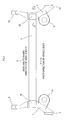
- a torsion beam type suspension of the embodiment of the present invention is configured by connecting a left trailing arm 1 to a right trailing arm 2 by a torsion beam 4 extending in a width direction of a vehicle body perpendicular to a back-and-forward direction of the vehicle body.
- the trailing arm 1 and the trailing arm 2 are left-right symmetric.
- the pair of left and right trailing arms 1 and 2 is formed by bending a hollow pipe having a circular shaped cross section.
- a collar 6 is attached firmly, by welding, to one end of the left trailing arm 1.
- the left trailing arm 1 is swingably supported by the not-illustrated vehicle body via the collar 6.
- a vehicle wheel supporting member 8 is attached firmly, by welding, to the other end of the trailing arm 1.
- the not-illustrated vehicle wheel is rotatably mounted on the vehicle wheel supporting member 8.
- a spring receiving member 10 is attached firmly to the left trailing arm 1 by welding.
- a coil spring is disposed between the spring receiving member 10 and the not-illustrated vehicle body.
- a collar 12 is attached to one end of the right trailing arm 2, and a vehicle wheel supporting member 14 is attached firmly, by welding, to the other end of the right trailing arm 2.
- a spring receiving member 16 is attached firmly, by welding, to the right trailing arm 2.
- the torsion beam 4 is pressed into an opening cross-sectional shape by folding a plate member.
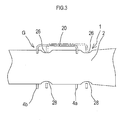
- the cross-sectional shape is formed into an approximately U-shape or V-shape, i.e., into a saddle-like shape opening towards the lowerside of the vehicle body (see FIG. 3 ).
- expanded portions 18 and 20 are formed at both ends of the torsion beam 4, which bulge outwardly in a radial direction of the trailing arms 1 and 2.
- the expanded portions 18 and 20 bulge as if expanding outwardly from the outer peripheries of the trailing arms 1 and 2.
- Cutouts 22 are formed at both of the expanded portions 18 and 20 (here, only one of the cutouts 22 being illustrated). As illustrated in FIG. 2 , the cutout 22 is formed at the expanded portion 20 of the torsion beam 4 at the side of the right trailing arm 2. The cutout 22 is formed in correspondence to the cross-sectional shape of the trailing arm 2, and, as illustrated in FIG. 3 , the cutout 22 is formed penetrating along the axial direction of the trailing arm 2.
- the torsion beam 4 is formed into an approximately U-shaped cross-sectional shape
- the cutout 22 is formed penetrating both side walls 4a and 4b.
- the cutout 22 includes an opening 24 formed opening towards the trailing arm 2.
- the cutout 22 is formed into an approximately arc-shape so that an inner periphery of the cutout 22 comes in contact with the outer periphery of the trailing arm 2, i.e., so that the cutout 22 receives the trailing arm 2, when a joining portion G of the trailing arm 2 is inserted into the cutout 22.
- the trailing arm 2 has the joining position G and an inserting position I.
- the joining position G of the trailing arm 2 is a position where both ends of the torsion beam 4 are connected, by welding, to the trailing arms 1 and 2.
- the inserting position I is provided at the trailing arm 2 in the vicinity of the joining position G.
- the inserting position I is formed with grooves 26 and 28.
- two grooves 26 are formed at an upper-side outer periphery of the trailing arm 2
- two grooves 28 are formed at a lower-side outer periphery of the trailing arm 2.
- the grooves 26 and 28 are arranged approximately in parallel, respectively.
- the upper-side grooves 26 and the lower-side grooves 28 are formed at the same relative positions along the axial direction of the trailing arm 2.
- the interval between the two upper-side grooves 26 is formed to be the same as the interval between the side walls 4a and 4b of the torsion beam 4 having the approximately U-shaped cross section.
- the cutout 22 is configured such that the torsion beam 4 surrounds half or more of the outer periphery of the trailing arm 2 in a state where the trailing arm 2 is inserted into the cutout 22 of the torsion beam 4 and then the torsion beam 4 has moved to the joining position G. Accordingly, the opening 24 is formed into a size such that, even if the trailing arm 2 is to be inserted into the cutout 22 through the opening 24, at the joining position G of the trailing arm 2, the end of the torsion beam 4 impacts the outer periphery of the trailing arm 2 and the trailing arm 2 is not able to be inserted.
- the interval between the bottom of the upper-side groove 26 and the bottom of the lower-side groove 28 is formed smaller than the clearance of the opening 24. Therefore, it is configured such that the trailing arm 2 is inserted into the cutout 22 from the radial direction by aligning the upper-side and lower-side grooves 26 and 28 to the cutout 22.
- the torsion beam 4 is moved to the joining position G by moving the torsion beam 4 in the axial direction of the trailing arm 2 after inserting the trailing arm 2 into the cutout 22.
- the torsion beam 4 and the trailing arm 2 are connected together by welding along the torsion beam 4 after moving the torsion beam 4 to the joining position G.
- the same cutout as the cutout 22 at the side of the trailing arm 2 is formed at the end of the torsion beam 4 at the side of the left trailing arm 1.
- the left trailing arm 1 is also formed with a joining position G and an inserting position I having grooves.
- the collars 6 and 12 are welded to the ends thereof, the vehicle wheel supporting members 8 and 14 are welded to the other ends thereof, and the spring receiving members 10 and 16 are welded thereto, respectively.
- the cutout 22 at the right-side end of the torsion beam 4 is aligned to the grooves 26 and 28 of the inserting position I of the right trailing arm 2, and then the trailing arm 2 is inserted into the cutout 22 through the opening 24 at the grooves 26 and 28.
- the torsion beam 4 is moved relatively in the axial direction of the trailing arm 2, and then the cutout 22 of the torsion beam 4 is aligned to the joining position G of the trailing arm 2. Accordingly, the outer periphery of the trailing arm 2 comes into contact with the cutout 22 with no clearance therebetween, and the trailing arm 2 is connected to the torsion beam 4 by welding along the cutout 22.
- the left trailing arm 1 is connected to the torsion beam 4 by welding in the same manner.
- the torsion beam type suspension moves up and down in that orientation and no twisting occurs.
- the vehicle body inclines, for example, by the centrifugal force applied to the vehicle body and the left and right wheels travel in opposite directions relative to the vehicle body, the torsion beam 4 is twisted and torsional reaction force is generated in proportion to its torsional stiffness.
- the torsion beam 4 has been welded to half or more of the outer periphery of each of the trailing arms 1 and 2, and it is thus possible to keep the welded length long, and the stress can be spread and generation of an excessive amount of stress due to stress concentration can be inhibited.
- the torsion beam 4 is connected, by welding, to the left and right trailing arms 1 and 2, without employing gussets, thereby enabling to reduce the number of components. Further, the torsion beam 4 can be connected to the trailing arms 1 and 2 maintaining the welded length shorter than the welded length obtained when welding the gussets, thereby enabling to reduce the welded length. Still further, the torsion beam type suspension according to the embodiment can be reduced in weight because gussets are not employed.
- a configuration that the grooves 26 and 28 are formed at the inserting position I is employed as an example, as illustrated in FIG. 4A .
- the configuration is not limited to the above and may be such that the trailing arm 2 is inserted into the cutout 22 through the opening 24 without forming the grooves 26 and 28 on the trailing arm 2 and by setting the diameter of the trailing arm 2 smaller than the clearance of the opening 24.
- the cross-sectional shape of the inserting position I may be oval, oblong, round, or the like.
Landscapes
- Engineering & Computer Science (AREA)
- Mechanical Engineering (AREA)
- Vehicle Body Suspensions (AREA)
Abstract
Description
- This international application claims the benefit of Japanese Patent Application No.
2011-040528 filed February 25, 2011 2011-040528 - The present invention relates to a torsion beam type suspension in which a pair of left and right trailing arms for a vehicle is connected by a torsion beam.
- Conventionally, regarding a vehicle, a torsion beam type suspension is known in which a pair of left and right trailing arms is connected by a torsion beam. With such torsion beam type suspension, for example as seen from a
Patent Document 1, the torsion beam are welded and connected to the left and right trailing arms, and cutouts are formed at both ends of the torsion beam. The cutouts correspond to the cross-sectional shape of the trailing arms so that the trailing arms inserted into the cutouts are welded to the torsion beam. Further, gussets are arranged over the torsion beam and the trailing arms, and the gussets are also formed with cutouts corresponding to the cross-sectional shape of the trailing arms. Thus, the cutouts of both the torsion beam and the gussets each surround half or more of the outer periphery of the trailing arms, whereby the welded length is ensured and strength and durability are satisfied. - Patent Document 1: Japanese Unexamined Patent Application Publication No.
2005-8123 - In such a conventional one, the gussets are needed to ensure the welded length, and thus the gussets are required to be formed into a shape appropriate for reinforcing. However, this forming is bothersome and leads to increase in the number of components and weight, and the gussets are welded to the trailing arms and the torsion beam, causing a problem of elongation of the welded length.
- It is preferable to provide a torsion beam type suspension in which the number of components can be reduced, the welded length can be shortened, and weight saving can be achieved.
- The present invention is a torsion beam type suspension including a pair of left and right hollow trailing arms and a torsion beam connecting the pair of left and right trailing arms. Each of the trailing arms is swingably supported at one end side of the trailing arm by a vehicle body and rotatably supports a vehicle wheel at the other end side of the trailing arm The torsion beam has at both ends cutouts formed in correspondence to a cross-sectional shape of the trailing arms. Each of the cutouts has an opening configured to receive a corresponding trailing arm of the trailing arms. The trailing arm has a joining position to which the torsion beam is connected by welding and an inserting position where the trailing arm is allowed to be inserted into the cutout through the opening. The opening is configured to be a size such that, when the torsion beam is located at the joining position, the torsion beam surrounds half or more of an outer periphery of the trailing arm inserted into the cutout and the trailing arm is not allowed to be inserted into the opening of the cutout. When the torsion beam is located at the inserting position, the trailing arm is connected to the torsion beam by inserting the trailing arm through the opening of the cutout, then by moving the torsion beam relative to the trailing arm along an axial direction of the trailing arm, and then by welding at the joining position.
- It may be configured such that the inserting position is formed with a groove recessed at the outer periphery of the trailing arm, and the trailing arm is allowed to be inserted into the cutout by aligning the opening of the cutout of the torsion beam to the groove. In this case, the grooves may be formed at upper-side and lower-side of the outer periphery of the trailing arm and approximately in parallel. Further, the joining position and the inserting position may be arranged next to each other. Still further, the both ends of the torsion beam may be configured to expand outwardly in the radial direction of the trailing arm and to be formed with the cutouts.
- According to the torsion beam type suspension of the present invention, since the trailing arms are welded to the torsion beam while the torsion beam surrounds half or more of the outer periphery of each of the trailing arms inserted into the cutouts, it is possible to keep the welded length long. Further, since the torsion beam is connected to the trailing arms without employing gussets, effects can be achieved to reduce the number of components and to reduce in weight.
- Forming the grooves at the inserting position of the trailing arm allows the trailing arm to be inserted through the opening of the cutout. Further, the grooves can be formed easily by forming the grooves at the upper side and lower side of the trailing arm and approximately in parallel. Still further, assembling becomes easier by arranging the joining position and the inserting position next to each other. The cutout can be easily formed by expanding the both ends of the torsion beam and by forming the cutout.
-
-
FIG. 1 is a plan view of a torsion beam type suspension according to an embodiment of the present invention. -
FIG. 2 is an enlarged cross-sectional view taken along a line II-II inFIG. 1 . -
FIG. 3 is a view seen from an arrow III inFIG. 2 . -
FIGS. 4A-4C are views enlarging major portions of a trailing arm of the embodiment. - 1, 2...trailing arm, 4...torsion beam, 4a, 4b...side wall, 6, 12...collar, 8, 14...vehicle wheel supporting member, 10, 16...spring receiving member, 18, 20...expanded portion, 22...cutout, 24...opening, 26, 28... groove
- Hereinafter, an embodiment for carrying out the present invention will be described in detail with reference to the drawings.
As illustrated inFIG. 1 , a torsion beam type suspension of the embodiment of the present invention is configured by connecting a lefttrailing arm 1 to a right trailingarm 2 by a torsion beam 4 extending in a width direction of a vehicle body perpendicular to a back-and-forward direction of the vehicle body. Thetrailing arm 1 and thetrailing arm 2 are left-right symmetric. The pair of left and right trailingarms - A
collar 6 is attached firmly, by welding, to one end of the left trailingarm 1. The lefttrailing arm 1 is swingably supported by the not-illustrated vehicle body via thecollar 6. Further, a vehiclewheel supporting member 8 is attached firmly, by welding, to the other end of thetrailing arm 1. The not-illustrated vehicle wheel is rotatably mounted on the vehiclewheel supporting member 8. Still further, aspring receiving member 10 is attached firmly to the left trailingarm 1 by welding. A coil spring is disposed between thespring receiving member 10 and the not-illustrated vehicle body. - As is the case with the aforementioned left
trailing arm 1, also for the righttrailing arm 2, acollar 12 is attached to one end of the righttrailing arm 2, and a vehiclewheel supporting member 14 is attached firmly, by welding, to the other end of the right trailingarm 2. Aspring receiving member 16 is attached firmly, by welding, to the right trailingarm 2. - The torsion beam 4 is pressed into an opening cross-sectional shape by folding a plate member. The cross-sectional shape is formed into an approximately U-shape or V-shape, i.e., into a saddle-like shape opening towards the lowerside of the vehicle body (see
FIG. 3 ). - According to the embodiment, expanded
portions arms portions trailing arms -
Cutouts 22 are formed at both of the expandedportions 18 and 20 (here, only one of thecutouts 22 being illustrated). As illustrated inFIG. 2 , thecutout 22 is formed at the expandedportion 20 of the torsion beam 4 at the side of the right trailingarm 2. Thecutout 22 is formed in correspondence to the cross-sectional shape of thetrailing arm 2, and, as illustrated inFIG. 3 , thecutout 22 is formed penetrating along the axial direction of thetrailing arm 2. - According to the embodiment, the torsion beam 4 is formed into an approximately U-shaped cross-sectional shape, and the
cutout 22 is formed penetrating bothside walls cutout 22 includes an opening 24 formed opening towards thetrailing arm 2. Thecutout 22 is formed into an approximately arc-shape so that an inner periphery of thecutout 22 comes in contact with the outer periphery of thetrailing arm 2, i.e., so that thecutout 22 receives thetrailing arm 2, when a joining portion G of thetrailing arm 2 is inserted into thecutout 22. - As illustrated in
FIG. 3 , the trailingarm 2 has the joining position G and an inserting position I. As illustrated inFIG. 1 , the joining position G of the trailingarm 2 is a position where both ends of the torsion beam 4 are connected, by welding, to the trailingarms arm 2 in the vicinity of the joining position G. - As illustrated in
FIG. 3 , the inserting position I is formed withgrooves grooves 26 are formed at an upper-side outer periphery of the trailingarm 2, and twogrooves 28 are formed at a lower-side outer periphery of the trailingarm 2. Thegrooves - The upper-
side grooves 26 and the lower-side grooves 28 are formed at the same relative positions along the axial direction of the trailingarm 2. The interval between the two upper-side grooves 26 is formed to be the same as the interval between theside walls - The
cutout 22 is configured such that the torsion beam 4 surrounds half or more of the outer periphery of the trailingarm 2 in a state where the trailingarm 2 is inserted into thecutout 22 of the torsion beam 4 and then the torsion beam 4 has moved to the joining position G. Accordingly, theopening 24 is formed into a size such that, even if the trailingarm 2 is to be inserted into thecutout 22 through theopening 24, at the joining position G of the trailingarm 2, the end of the torsion beam 4 impacts the outer periphery of the trailingarm 2 and the trailingarm 2 is not able to be inserted. - Further, the interval between the bottom of the upper-
side groove 26 and the bottom of the lower-side groove 28 is formed smaller than the clearance of theopening 24. Therefore, it is configured such that the trailingarm 2 is inserted into thecutout 22 from the radial direction by aligning the upper-side and lower-side grooves cutout 22. - Further, it is configured such that the torsion beam 4 is moved to the joining position G by moving the torsion beam 4 in the axial direction of the trailing
arm 2 after inserting the trailingarm 2 into thecutout 22. The torsion beam 4 and the trailingarm 2 are connected together by welding along the torsion beam 4 after moving the torsion beam 4 to the joining position G. The same cutout as thecutout 22 at the side of the trailingarm 2 is formed at the end of the torsion beam 4 at the side of theleft trailing arm 1. Theleft trailing arm 1 is also formed with a joining position G and an inserting position I having grooves. - Next described below is a method of assembling the torsion beam type suspension of the embodiment. Regarding the left and right trailing
arms collars wheel supporting members spring receiving members FIGS. 2 and3 , thecutout 22 at the right-side end of the torsion beam 4 is aligned to thegrooves right trailing arm 2, and then the trailingarm 2 is inserted into thecutout 22 through theopening 24 at thegrooves - Then, the torsion beam 4 is moved relatively in the axial direction of the trailing
arm 2, and then thecutout 22 of the torsion beam 4 is aligned to the joining position G of the trailingarm 2. Accordingly, the outer periphery of the trailingarm 2 comes into contact with thecutout 22 with no clearance therebetween, and the trailingarm 2 is connected to the torsion beam 4 by welding along thecutout 22. Theleft trailing arm 1 is connected to the torsion beam 4 by welding in the same manner. - Next, an operation of the torsion beam type suspension of the embodiment will be described. During the vehicle running, when both left and right wheels travel in the same direction and at the same amount relative to the vehicle body, the torsion beam type suspension moves up and down in that orientation and no twisting occurs. However, when the vehicle body inclines, for example, by the centrifugal force applied to the vehicle body and the left and right wheels travel in opposite directions relative to the vehicle body, the torsion beam 4 is twisted and torsional reaction force is generated in proportion to its torsional stiffness.
- Stress due to the torsional reaction force is generated at the welded portions between the torsion beam 4 and the trailing
arms arms - As described above, the torsion beam 4 is connected, by welding, to the left and right trailing
arms arms - According to the embodiment, a configuration that the
grooves FIG. 4A . However, the configuration is not limited to the above and may be such that the trailingarm 2 is inserted into thecutout 22 through theopening 24 without forming thegrooves arm 2 and by setting the diameter of the trailingarm 2 smaller than the clearance of theopening 24. In this case, the cross-sectional shape of the inserting position I may be oval, oblong, round, or the like. - The present invention has been described with reference to exemplary embodiments. However, it will be readily apparent to those skilled in the art that it is possible to employ the invention in specific forms other than as described above without departing from the spirit of the invention.
Claims (5)
- A torsion beam type suspension comprising:a pair of left and right hollow trailing arms, each of the trailing arms swingably supported at one end side of the trailing arm by a vehicle body and rotatably supporting a vehicle wheel at the other end side of the trailing arm;a torsion beam connecting the pair of left and right trailing arms,the torsion beam having at both ends cutouts formed in correspondence to a cross-sectional shape of the trailing arms, each of the cutouts having an opening configured to receive a corresponding trailing arm of the trailing arms,the trailing arm having a joining position to which the torsion beam is connected by welding and an inserting position where the trailing arm is allowed to be inserted into the cutout through the opening,the opening being configured to be a size such that, when the torsion beam is located at the joining position, the torsion beam surrounds half or more of an outer periphery of the trailing arm inserted into the cutout and the trailing arm is not allowed to be inserted into the opening of the cutout from a radial direction of the trailing arm, andwherein, when the torsion beam is located at the inserting position, the trailing arm is connected to the torsion beam by inserting the trailing arm through the opening of the cutout, then by moving the torsion beam relative to the trailing arm along an axial direction of the trailing arm, and then by welding at the joining position.
- The torsion beam type suspension according to claim 1, wherein the inserting position is formed with a groove recessed at the outer periphery of the trailing arm, and the trailing arm is allowed to be inserted into the cutout by aligning the opening of the cutout of the torsion beam to the groove.
- The torsion beam type suspension according to claim 2, wherein the groove is formed at upper-side and lower-side of the outer periphery of the trailing arm and approximately in parallel.
- The torsion beam type suspension according to any one of claims 1 to 3, wherein the joining position and the inserting position are arranged next to each other.
- The torsion beam type suspension according to any one of claims 1 to 4, wherein the both ends of the torsion beam bulge outwardly in the radial direction of the trailing arm and are formed with the cutouts.
Applications Claiming Priority (2)
| Application Number | Priority Date | Filing Date | Title |
|---|---|---|---|
| JP2011040528A JP5703062B2 (en) | 2011-02-25 | 2011-02-25 | Torsion beam suspension |
| PCT/JP2012/054410 WO2012115186A1 (en) | 2011-02-25 | 2012-02-23 | Torsion beam type suspension |
Publications (3)
| Publication Number | Publication Date |
|---|---|
| EP2679416A1 true EP2679416A1 (en) | 2014-01-01 |
| EP2679416A4 EP2679416A4 (en) | 2014-09-24 |
| EP2679416B1 EP2679416B1 (en) | 2018-05-02 |
Family
ID=46720960
Family Applications (1)
| Application Number | Title | Priority Date | Filing Date |
|---|---|---|---|
| EP12749628.9A Not-in-force EP2679416B1 (en) | 2011-02-25 | 2012-02-23 | Torsion beam type suspension |
Country Status (4)
| Country | Link |
|---|---|
| EP (1) | EP2679416B1 (en) |
| JP (1) | JP5703062B2 (en) |
| CN (1) | CN103380012B (en) |
| WO (1) | WO2012115186A1 (en) |
Families Citing this family (6)
| Publication number | Priority date | Publication date | Assignee | Title |
|---|---|---|---|---|
| JP6001264B2 (en) * | 2011-12-16 | 2016-10-05 | フタバ産業株式会社 | Torsion beam suspension |
| JP6136523B2 (en) * | 2013-04-23 | 2017-05-31 | スズキ株式会社 | Torsion beam suspension |
| JP6395043B2 (en) * | 2014-10-07 | 2018-09-26 | スズキ株式会社 | Torsion beam suspension |
| JP7028107B2 (en) * | 2018-08-31 | 2022-03-02 | トヨタ紡織株式会社 | Seat frame |
| JP7441680B2 (en) * | 2020-03-05 | 2024-03-01 | 株式会社エフテック | Torsion beam suspension |
| CN113525013A (en) * | 2021-07-20 | 2021-10-22 | 安徽大昌科技股份有限公司 | Combined type torsion beam longitudinal arm structure |
Family Cites Families (9)
| Publication number | Priority date | Publication date | Assignee | Title |
|---|---|---|---|---|
| US6533300B1 (en) * | 2000-06-02 | 2003-03-18 | Oxford Suspension, Inc. | Trailing twist axle and method of manufacture |
| JP2002120534A (en) * | 2000-10-16 | 2002-04-23 | Mitsubishi Motors Corp | Rear suspension |
| CN100387449C (en) * | 2002-07-04 | 2008-05-14 | 本田技研工业株式会社 | Torsion beam type suspension |
| FR2861647B1 (en) * | 2003-10-29 | 2006-03-31 | Auto Chassis Int Snc | FLEXIBLE AXLE HAVING TRANSVERSE STIFFNESS INCREASED BY AT LEAST ONE SPRING CUTTING PART, SPRING CUP AND CORRESPONDING VEHICLE |
| JP4544001B2 (en) * | 2005-03-31 | 2010-09-15 | 三菱自動車工業株式会社 | Torsion beam type rear suspension structure |
| KR100958977B1 (en) * | 2007-07-25 | 2010-05-20 | 주식회사 포스코 | Tubular torsion beam for rear wheel suspension of automobile and manufacturing method thereof |
| JP2011088461A (en) * | 2009-10-20 | 2011-05-06 | Daihatsu Motor Co Ltd | Suspension structure |
| JP5398078B2 (en) * | 2010-03-05 | 2014-01-29 | ダイハツ工業株式会社 | Suspension device in vehicle |
| JP5513946B2 (en) * | 2010-03-18 | 2014-06-04 | ダイハツ工業株式会社 | Vehicle suspension system |
-
2011
- 2011-02-25 JP JP2011040528A patent/JP5703062B2/en not_active Expired - Fee Related
-
2012
- 2012-02-23 EP EP12749628.9A patent/EP2679416B1/en not_active Not-in-force
- 2012-02-23 WO PCT/JP2012/054410 patent/WO2012115186A1/en not_active Ceased
- 2012-02-23 CN CN201280009512.3A patent/CN103380012B/en not_active Expired - Fee Related
Also Published As
| Publication number | Publication date |
|---|---|
| CN103380012B (en) | 2016-01-20 |
| JP5703062B2 (en) | 2015-04-15 |
| JP2012176685A (en) | 2012-09-13 |
| WO2012115186A1 (en) | 2012-08-30 |
| CN103380012A (en) | 2013-10-30 |
| EP2679416B1 (en) | 2018-05-02 |
| EP2679416A4 (en) | 2014-09-24 |
Similar Documents
| Publication | Publication Date | Title |
|---|---|---|
| EP2679416A1 (en) | Torsion beam type suspension | |
| US9421838B2 (en) | Suspension arm | |
| US8398102B2 (en) | Suspension arm for a motor vehicle wheel suspension and method for manufacturing same | |
| KR101389229B1 (en) | Stress reducing inner sleeve for twist beam and associated method | |
| KR101399335B1 (en) | Rear suspension of coupled torsion beam axle type | |
| CN108473014A (en) | Vehicle mixing suspension link and its manufacturing method | |
| JP6380053B2 (en) | Torsion beam suspension structure | |
| US20170015166A1 (en) | Suspension structure for vehicle | |
| JP6363402B2 (en) | Torsion beam suspension | |
| EP2639089B1 (en) | Torsion beam axle having ring member friction-welded to trailing arm | |
| JP4544001B2 (en) | Torsion beam type rear suspension structure | |
| JP2000318420A (en) | Trailing arm type suspension | |
| JP6389281B2 (en) | Torsion beam suspension | |
| CN100450803C (en) | Stabilizer lateral deviation preventing device | |
| JP2016168953A (en) | Torsion beam-type suspension | |
| JP6061993B1 (en) | Front subframe stay fastening structure and front subframe body assembly method | |
| JP2011201330A (en) | Suspension device of vehicle | |
| KR20110095069A (en) | Suspension device for vehicle and manufacturing method thereof | |
| JP2011194963A (en) | Suspension device of vehicle | |
| JP5398078B2 (en) | Suspension device in vehicle | |
| KR20130006096A (en) | Rear suspension of coupled torsion beam axle type | |
| JP6662271B2 (en) | Vehicle suspension arm | |
| JP6430798B2 (en) | Vehicle suspension | |
| JP7425712B2 (en) | cable clamp | |
| JP6001264B2 (en) | Torsion beam suspension |
Legal Events
| Date | Code | Title | Description |
|---|---|---|---|
| PUAI | Public reference made under article 153(3) epc to a published international application that has entered the european phase |
Free format text: ORIGINAL CODE: 0009012 |
|
| 17P | Request for examination filed |
Effective date: 20130820 |
|
| AK | Designated contracting states |
Kind code of ref document: A1 Designated state(s): AL AT BE BG CH CY CZ DE DK EE ES FI FR GB GR HR HU IE IS IT LI LT LU LV MC MK MT NL NO PL PT RO RS SE SI SK SM TR |
|
| DAX | Request for extension of the european patent (deleted) | ||
| A4 | Supplementary search report drawn up and despatched |
Effective date: 20140821 |
|
| RIC1 | Information provided on ipc code assigned before grant |
Ipc: B60G 9/04 20060101AFI20140815BHEP Ipc: B60G 21/055 20060101ALI20140815BHEP |
|
| RAP1 | Party data changed (applicant data changed or rights of an application transferred) |
Owner name: FUTABA INDUSTRIAL CO. LTD. |
|
| GRAP | Despatch of communication of intention to grant a patent |
Free format text: ORIGINAL CODE: EPIDOSNIGR1 |
|
| STAA | Information on the status of an ep patent application or granted ep patent |
Free format text: STATUS: GRANT OF PATENT IS INTENDED |
|
| INTG | Intention to grant announced |
Effective date: 20171116 |
|
| GRAS | Grant fee paid |
Free format text: ORIGINAL CODE: EPIDOSNIGR3 |
|
| GRAA | (expected) grant |
Free format text: ORIGINAL CODE: 0009210 |
|
| STAA | Information on the status of an ep patent application or granted ep patent |
Free format text: STATUS: THE PATENT HAS BEEN GRANTED |
|
| AK | Designated contracting states |
Kind code of ref document: B1 Designated state(s): AL AT BE BG CH CY CZ DE DK EE ES FI FR GB GR HR HU IE IS IT LI LT LU LV MC MK MT NL NO PL PT RO RS SE SI SK SM TR |
|
| REG | Reference to a national code |
Ref country code: GB Ref legal event code: FG4D |
|
| REG | Reference to a national code |
Ref country code: CH Ref legal event code: EP Ref country code: AT Ref legal event code: REF Ref document number: 994806 Country of ref document: AT Kind code of ref document: T Effective date: 20180515 |
|
| REG | Reference to a national code |
Ref country code: DE Ref legal event code: R096 Ref document number: 602012045930 Country of ref document: DE Ref country code: IE Ref legal event code: FG4D |
|
| REG | Reference to a national code |
Ref country code: NL Ref legal event code: MP Effective date: 20180502 |
|
| REG | Reference to a national code |
Ref country code: LT Ref legal event code: MG4D |
|
| PG25 | Lapsed in a contracting state [announced via postgrant information from national office to epo] |
Ref country code: LT Free format text: LAPSE BECAUSE OF FAILURE TO SUBMIT A TRANSLATION OF THE DESCRIPTION OR TO PAY THE FEE WITHIN THE PRESCRIBED TIME-LIMIT Effective date: 20180502 Ref country code: ES Free format text: LAPSE BECAUSE OF FAILURE TO SUBMIT A TRANSLATION OF THE DESCRIPTION OR TO PAY THE FEE WITHIN THE PRESCRIBED TIME-LIMIT Effective date: 20180502 Ref country code: NO Free format text: LAPSE BECAUSE OF FAILURE TO SUBMIT A TRANSLATION OF THE DESCRIPTION OR TO PAY THE FEE WITHIN THE PRESCRIBED TIME-LIMIT Effective date: 20180802 Ref country code: SE Free format text: LAPSE BECAUSE OF FAILURE TO SUBMIT A TRANSLATION OF THE DESCRIPTION OR TO PAY THE FEE WITHIN THE PRESCRIBED TIME-LIMIT Effective date: 20180502 Ref country code: BG Free format text: LAPSE BECAUSE OF FAILURE TO SUBMIT A TRANSLATION OF THE DESCRIPTION OR TO PAY THE FEE WITHIN THE PRESCRIBED TIME-LIMIT Effective date: 20180802 Ref country code: FI Free format text: LAPSE BECAUSE OF FAILURE TO SUBMIT A TRANSLATION OF THE DESCRIPTION OR TO PAY THE FEE WITHIN THE PRESCRIBED TIME-LIMIT Effective date: 20180502 |
|
| PG25 | Lapsed in a contracting state [announced via postgrant information from national office to epo] |
Ref country code: GR Free format text: LAPSE BECAUSE OF FAILURE TO SUBMIT A TRANSLATION OF THE DESCRIPTION OR TO PAY THE FEE WITHIN THE PRESCRIBED TIME-LIMIT Effective date: 20180803 Ref country code: RS Free format text: LAPSE BECAUSE OF FAILURE TO SUBMIT A TRANSLATION OF THE DESCRIPTION OR TO PAY THE FEE WITHIN THE PRESCRIBED TIME-LIMIT Effective date: 20180502 Ref country code: LV Free format text: LAPSE BECAUSE OF FAILURE TO SUBMIT A TRANSLATION OF THE DESCRIPTION OR TO PAY THE FEE WITHIN THE PRESCRIBED TIME-LIMIT Effective date: 20180502 Ref country code: NL Free format text: LAPSE BECAUSE OF FAILURE TO SUBMIT A TRANSLATION OF THE DESCRIPTION OR TO PAY THE FEE WITHIN THE PRESCRIBED TIME-LIMIT Effective date: 20180502 Ref country code: HR Free format text: LAPSE BECAUSE OF FAILURE TO SUBMIT A TRANSLATION OF THE DESCRIPTION OR TO PAY THE FEE WITHIN THE PRESCRIBED TIME-LIMIT Effective date: 20180502 |
|
| REG | Reference to a national code |
Ref country code: AT Ref legal event code: MK05 Ref document number: 994806 Country of ref document: AT Kind code of ref document: T Effective date: 20180502 |
|
| PG25 | Lapsed in a contracting state [announced via postgrant information from national office to epo] |
Ref country code: CZ Free format text: LAPSE BECAUSE OF FAILURE TO SUBMIT A TRANSLATION OF THE DESCRIPTION OR TO PAY THE FEE WITHIN THE PRESCRIBED TIME-LIMIT Effective date: 20180502 Ref country code: SK Free format text: LAPSE BECAUSE OF FAILURE TO SUBMIT A TRANSLATION OF THE DESCRIPTION OR TO PAY THE FEE WITHIN THE PRESCRIBED TIME-LIMIT Effective date: 20180502 Ref country code: DK Free format text: LAPSE BECAUSE OF FAILURE TO SUBMIT A TRANSLATION OF THE DESCRIPTION OR TO PAY THE FEE WITHIN THE PRESCRIBED TIME-LIMIT Effective date: 20180502 Ref country code: AT Free format text: LAPSE BECAUSE OF FAILURE TO SUBMIT A TRANSLATION OF THE DESCRIPTION OR TO PAY THE FEE WITHIN THE PRESCRIBED TIME-LIMIT Effective date: 20180502 Ref country code: PL Free format text: LAPSE BECAUSE OF FAILURE TO SUBMIT A TRANSLATION OF THE DESCRIPTION OR TO PAY THE FEE WITHIN THE PRESCRIBED TIME-LIMIT Effective date: 20180502 Ref country code: EE Free format text: LAPSE BECAUSE OF FAILURE TO SUBMIT A TRANSLATION OF THE DESCRIPTION OR TO PAY THE FEE WITHIN THE PRESCRIBED TIME-LIMIT Effective date: 20180502 Ref country code: RO Free format text: LAPSE BECAUSE OF FAILURE TO SUBMIT A TRANSLATION OF THE DESCRIPTION OR TO PAY THE FEE WITHIN THE PRESCRIBED TIME-LIMIT Effective date: 20180502 |
|
| REG | Reference to a national code |
Ref country code: DE Ref legal event code: R097 Ref document number: 602012045930 Country of ref document: DE |
|
| PG25 | Lapsed in a contracting state [announced via postgrant information from national office to epo] |
Ref country code: IT Free format text: LAPSE BECAUSE OF FAILURE TO SUBMIT A TRANSLATION OF THE DESCRIPTION OR TO PAY THE FEE WITHIN THE PRESCRIBED TIME-LIMIT Effective date: 20180502 Ref country code: SM Free format text: LAPSE BECAUSE OF FAILURE TO SUBMIT A TRANSLATION OF THE DESCRIPTION OR TO PAY THE FEE WITHIN THE PRESCRIBED TIME-LIMIT Effective date: 20180502 |
|
| PLBE | No opposition filed within time limit |
Free format text: ORIGINAL CODE: 0009261 |
|
| STAA | Information on the status of an ep patent application or granted ep patent |
Free format text: STATUS: NO OPPOSITION FILED WITHIN TIME LIMIT |
|
| 26N | No opposition filed |
Effective date: 20190205 |
|
| PG25 | Lapsed in a contracting state [announced via postgrant information from national office to epo] |
Ref country code: SI Free format text: LAPSE BECAUSE OF FAILURE TO SUBMIT A TRANSLATION OF THE DESCRIPTION OR TO PAY THE FEE WITHIN THE PRESCRIBED TIME-LIMIT Effective date: 20180502 |
|
| REG | Reference to a national code |
Ref country code: CH Ref legal event code: PL |
|
| GBPC | Gb: european patent ceased through non-payment of renewal fee |
Effective date: 20190223 |
|
| PG25 | Lapsed in a contracting state [announced via postgrant information from national office to epo] |
Ref country code: LU Free format text: LAPSE BECAUSE OF NON-PAYMENT OF DUE FEES Effective date: 20190223 Ref country code: MC Free format text: LAPSE BECAUSE OF FAILURE TO SUBMIT A TRANSLATION OF THE DESCRIPTION OR TO PAY THE FEE WITHIN THE PRESCRIBED TIME-LIMIT Effective date: 20180502 |
|
| REG | Reference to a national code |
Ref country code: BE Ref legal event code: MM Effective date: 20190228 |
|
| REG | Reference to a national code |
Ref country code: IE Ref legal event code: MM4A |
|
| PG25 | Lapsed in a contracting state [announced via postgrant information from national office to epo] |
Ref country code: AL Free format text: LAPSE BECAUSE OF FAILURE TO SUBMIT A TRANSLATION OF THE DESCRIPTION OR TO PAY THE FEE WITHIN THE PRESCRIBED TIME-LIMIT Effective date: 20180502 |
|
| PG25 | Lapsed in a contracting state [announced via postgrant information from national office to epo] |
Ref country code: CH Free format text: LAPSE BECAUSE OF NON-PAYMENT OF DUE FEES Effective date: 20190228 Ref country code: LI Free format text: LAPSE BECAUSE OF NON-PAYMENT OF DUE FEES Effective date: 20190228 |
|
| PG25 | Lapsed in a contracting state [announced via postgrant information from national office to epo] |
Ref country code: GB Free format text: LAPSE BECAUSE OF NON-PAYMENT OF DUE FEES Effective date: 20190223 Ref country code: IE Free format text: LAPSE BECAUSE OF NON-PAYMENT OF DUE FEES Effective date: 20190223 |
|
| PG25 | Lapsed in a contracting state [announced via postgrant information from national office to epo] |
Ref country code: BE Free format text: LAPSE BECAUSE OF NON-PAYMENT OF DUE FEES Effective date: 20190228 Ref country code: FR Free format text: LAPSE BECAUSE OF NON-PAYMENT OF DUE FEES Effective date: 20190228 |
|
| PG25 | Lapsed in a contracting state [announced via postgrant information from national office to epo] |
Ref country code: TR Free format text: LAPSE BECAUSE OF FAILURE TO SUBMIT A TRANSLATION OF THE DESCRIPTION OR TO PAY THE FEE WITHIN THE PRESCRIBED TIME-LIMIT Effective date: 20180502 |
|
| PG25 | Lapsed in a contracting state [announced via postgrant information from national office to epo] |
Ref country code: MT Free format text: LAPSE BECAUSE OF NON-PAYMENT OF DUE FEES Effective date: 20190223 Ref country code: PT Free format text: LAPSE BECAUSE OF FAILURE TO SUBMIT A TRANSLATION OF THE DESCRIPTION OR TO PAY THE FEE WITHIN THE PRESCRIBED TIME-LIMIT Effective date: 20180903 |
|
| PG25 | Lapsed in a contracting state [announced via postgrant information from national office to epo] |
Ref country code: CY Free format text: LAPSE BECAUSE OF FAILURE TO SUBMIT A TRANSLATION OF THE DESCRIPTION OR TO PAY THE FEE WITHIN THE PRESCRIBED TIME-LIMIT Effective date: 20180502 |
|
| PG25 | Lapsed in a contracting state [announced via postgrant information from national office to epo] |
Ref country code: IS Free format text: LAPSE BECAUSE OF FAILURE TO SUBMIT A TRANSLATION OF THE DESCRIPTION OR TO PAY THE FEE WITHIN THE PRESCRIBED TIME-LIMIT Effective date: 20180902 |
|
| PG25 | Lapsed in a contracting state [announced via postgrant information from national office to epo] |
Ref country code: HU Free format text: LAPSE BECAUSE OF FAILURE TO SUBMIT A TRANSLATION OF THE DESCRIPTION OR TO PAY THE FEE WITHIN THE PRESCRIBED TIME-LIMIT; INVALID AB INITIO Effective date: 20120223 |
|
| PG25 | Lapsed in a contracting state [announced via postgrant information from national office to epo] |
Ref country code: MK Free format text: LAPSE BECAUSE OF FAILURE TO SUBMIT A TRANSLATION OF THE DESCRIPTION OR TO PAY THE FEE WITHIN THE PRESCRIBED TIME-LIMIT Effective date: 20180502 |
|
| PGFP | Annual fee paid to national office [announced via postgrant information from national office to epo] |
Ref country code: DE Payment date: 20220620 Year of fee payment: 12 |
|
| REG | Reference to a national code |
Ref country code: DE Ref legal event code: R119 Ref document number: 602012045930 Country of ref document: DE |
|
| PG25 | Lapsed in a contracting state [announced via postgrant information from national office to epo] |
Ref country code: DE Free format text: LAPSE BECAUSE OF NON-PAYMENT OF DUE FEES Effective date: 20240903 |
|
| PG25 | Lapsed in a contracting state [announced via postgrant information from national office to epo] |
Ref country code: DE Free format text: LAPSE BECAUSE OF NON-PAYMENT OF DUE FEES Effective date: 20240903 |