EP2679367B1 - Tire vulcanization device - Google Patents
Tire vulcanization device Download PDFInfo
- Publication number
- EP2679367B1 EP2679367B1 EP11817288.1A EP11817288A EP2679367B1 EP 2679367 B1 EP2679367 B1 EP 2679367B1 EP 11817288 A EP11817288 A EP 11817288A EP 2679367 B1 EP2679367 B1 EP 2679367B1
- Authority
- EP
- European Patent Office
- Prior art keywords
- platen
- divided
- platens
- tire
- concave
- Prior art date
- Legal status (The legal status is an assumption and is not a legal conclusion. Google has not performed a legal analysis and makes no representation as to the accuracy of the status listed.)
- Not-in-force
Links
Images


Classifications
-
- B—PERFORMING OPERATIONS; TRANSPORTING
- B29—WORKING OF PLASTICS; WORKING OF SUBSTANCES IN A PLASTIC STATE IN GENERAL
- B29C—SHAPING OR JOINING OF PLASTICS; SHAPING OF MATERIAL IN A PLASTIC STATE, NOT OTHERWISE PROVIDED FOR; AFTER-TREATMENT OF THE SHAPED PRODUCTS, e.g. REPAIRING
- B29C33/00—Moulds or cores; Details thereof or accessories therefor
- B29C33/02—Moulds or cores; Details thereof or accessories therefor with incorporated heating or cooling means
- B29C33/04—Moulds or cores; Details thereof or accessories therefor with incorporated heating or cooling means using liquids, gas or steam
-
- B—PERFORMING OPERATIONS; TRANSPORTING
- B29—WORKING OF PLASTICS; WORKING OF SUBSTANCES IN A PLASTIC STATE IN GENERAL
- B29C—SHAPING OR JOINING OF PLASTICS; SHAPING OF MATERIAL IN A PLASTIC STATE, NOT OTHERWISE PROVIDED FOR; AFTER-TREATMENT OF THE SHAPED PRODUCTS, e.g. REPAIRING
- B29C33/00—Moulds or cores; Details thereof or accessories therefor
- B29C33/02—Moulds or cores; Details thereof or accessories therefor with incorporated heating or cooling means
-
- B—PERFORMING OPERATIONS; TRANSPORTING
- B29—WORKING OF PLASTICS; WORKING OF SUBSTANCES IN A PLASTIC STATE IN GENERAL
- B29C—SHAPING OR JOINING OF PLASTICS; SHAPING OF MATERIAL IN A PLASTIC STATE, NOT OTHERWISE PROVIDED FOR; AFTER-TREATMENT OF THE SHAPED PRODUCTS, e.g. REPAIRING
- B29C33/00—Moulds or cores; Details thereof or accessories therefor
- B29C33/20—Opening, closing or clamping
-
- B—PERFORMING OPERATIONS; TRANSPORTING
- B29—WORKING OF PLASTICS; WORKING OF SUBSTANCES IN A PLASTIC STATE IN GENERAL
- B29C—SHAPING OR JOINING OF PLASTICS; SHAPING OF MATERIAL IN A PLASTIC STATE, NOT OTHERWISE PROVIDED FOR; AFTER-TREATMENT OF THE SHAPED PRODUCTS, e.g. REPAIRING
- B29C35/00—Heating, cooling or curing, e.g. crosslinking or vulcanising; Apparatus therefor
- B29C35/02—Heating or curing, e.g. crosslinking or vulcanizing during moulding, e.g. in a mould
- B29C35/04—Heating or curing, e.g. crosslinking or vulcanizing during moulding, e.g. in a mould using liquids, gas or steam
-
- B—PERFORMING OPERATIONS; TRANSPORTING
- B29—WORKING OF PLASTICS; WORKING OF SUBSTANCES IN A PLASTIC STATE IN GENERAL
- B29D—PRODUCING PARTICULAR ARTICLES FROM PLASTICS OR FROM SUBSTANCES IN A PLASTIC STATE
- B29D30/00—Producing pneumatic or solid tyres or parts thereof
- B29D30/06—Pneumatic tyres or parts thereof (e.g. produced by casting, moulding, compression moulding, injection moulding, centrifugal casting)
- B29D30/0601—Vulcanising tyres; Vulcanising presses for tyres
- B29D30/0662—Accessories, details or auxiliary operations
- B29D2030/0666—Heating by using fluids
- B29D2030/0674—Heating by using non-fluid means, e.g. electrical heating
-
- B—PERFORMING OPERATIONS; TRANSPORTING
- B29—WORKING OF PLASTICS; WORKING OF SUBSTANCES IN A PLASTIC STATE IN GENERAL
- B29L—INDEXING SCHEME ASSOCIATED WITH SUBCLASS B29C, RELATING TO PARTICULAR ARTICLES
- B29L2030/00—Pneumatic or solid tyres or parts thereof
Definitions
- the present invention relates to a tire vulcanizer which vulcanizes and molds a green tire.
- an outer mold in which the green tire is placed, is heated, and the inner wall surface of the green tire is pressed toward the outer mold while being heated by a high-temperature and high-pressure heating medium being supplied to the inner space of the green tire (to the inside of the bladder). Then, the outer side and the inner side of the green tire are heated by the heated outer mold and the heating medium supplied to the inner space of the green tire, and thereby the green tire is vulcanized.
- the conventional tire vulcanizer is configured such that steam as a heating medium is supplied into and circulated through the inner space of the green tire; and such that a heated and pressurized medium, such as nitrogen gas and warm water, is sealed in the inner space.
- Patent Literature 5 described below discloses a tire vulcanizing mold in which, in order to obtain a uniform degree of vulcanization over the whole of a tire, the platen is divided in the radial direction thereof, and the rates of temperature increase of heating sections are correspondingly changed.
- a conventional platen 5 of an electric heating type has a doughnut-like disc shape in the center portion of which a circular through hole 6 is formed, and has a structure in which heat generating sections 7, such as rod-shaped heaters, are embedded.
- heat generating sections 7, such as rod-shaped heaters are embedded.
- the first problem is that, at the time of tire vulcanization, deformation (deflection) is easily generated in the circular platen. For this reason, the life of a heat generating section, such as an electric heater, embedded in the platen, and the life of an attaching member, and the like, are reduced under the influence of the stress generated due to the deformation of the platen. Also, the deformation of the platen means that the contact area between the outer mold and the heat generating section is reduced, and hence the heat transfer property (heating efficiency) between the outer mold and the heat generating section is reduced. Further, when the heat transfer property between the outer mold and the heat generating section is reduced, the temperature of the heat generating section is increased to an unexpected high temperature, and thereby the thermal life of the heat generating section is reduced.
- the second problem relates to the replacement of the platen at the time of.maintenance, and the like, and is that, in the work of replacing the platen having the one-piece structure, much time is required for the removal of and the attachment and adjustment of the platen. Further, when the platen is replaced due to a failure, or the like, the entire platen must be collectively replaced, which is disadvantageous from the viewpoint of cost.
- US-A-2024554 discloses a tire vulcanizer according to the preamble of claim 1.
- An object of the present invention is to provide a tire vulcanizer capable of solving the problems of the electrical heating platen, which relate to the deformation at the time of tire vulcanization and to the replacement of the platen.
- the present invention adopts the following means in order to solve the above-described problems.
- a tire vulcanizer according to the present invention which vulcanizes and molds a green tire placed in an outer mold by heating the green tire from the outside and the inside of the green tire, is featured by including an electric platen which is arranged to be in contact with each of the upper and lower sides of a container with the green tire placed therein, or to be embedded in each of the upper and lower portions of the container, so as to heat the green tire from the outside of the outer mold at the time of vulcanization, and which is formed into a doughnut-like disc shape and divided into a plurality of sections in the circumferential direction of the platen.
- the tire vulcanizer according to the present invention includes the electric platen which is arranged to be in contact with each of the upper and lower sides of the container with a green tire placed therein, or to be embedded in each of the upper and lower portions of the container, so as to heat the green tire from the outside of the outer mold at the time of vulcanization, and which is formed into the doughnut-like disc shape and divided into the plurality of sections in the circumferential direction of the platen. Therefore, the platen is hardly deformed at the time of tire vulcanization.
- the platen is divided into a plurality of sections in the radial direction of the platen and is formed into a doughnut-like disc shape by connecting the innermost sides of the divided sections in the circumferential direction.
- the divided platens are connected and formed into the doughnut-like disc shape at the innermost center portion of the platen, and hence a small diameter hole is formed at the center portion of the platen, so that the hole can be used for the centering at the time of attaching the platen.
- the platen includes a concave-convex engaging section in which concave and convex sections of the mutually adjacent divided platens of the plurality of divided platens are engaged with each other to make the mutually adjacent divided platens connected together and positioned.
- the platen may include a fastening connecting section in which the mutually adjacent divided platens of the plurality of divided platens are connected together and positioned by a fastening member.
- the platen may be configured to include a plate connecting section in which the mutually adjacent divided platens of the plurality of divided platens are connected together and positioned via a plate-shaped member.
- the platen may be divided into a plurality of divided platens of which the mutually adjacent divided platens are provided therebetween with two or more of the concave-convex engaging section, the fastening connecting section and the plate connecting section.
- the mutually adjacent divided platens can be easily positioned and connected with each other by the concave-convex engaging section, the fastening connecting section, and the plate connecting section, and by a combination of the concave-convex engaging section, the fastening connecting section, and the plate connecting section.
- connection and positioning in the plate connecting section may be performed in such a manner that the concave-convex section provided on the upper surface or the lower surface of the platen is engaged with the concave-convex section provided on the lower surface or the upper surface of the plate-shaped member.
- the platen and the plate-shaped member are connected together and positioned via a fastening member.
- the electrical heating platen of the tire vulcanizer is configured to be divided into a plurality of sections in the circumferential direction, and hence the platen is hardly deformed by the load at the time of tire vulcanization, as a result of which the heating efficiency, the durability, and the reliability of the platen are improved.
- the structure, in which the electrical heating platen is divided into a plurality of sections in the circumferential direction facilitates the work of attaching and removing the platen and the work of replacing the platen, and hence is effective for improving the maintainability of the platen.
- the replacement can be performed for each of the divided platens, and hence the cost required for replacing the components can be reduced.
- the structure in which the electrical heating platen is divided into a plurality of sections, enables an optimum division shape to be selected in correspondence with the structure of the vulcanizer, the tire mold, and the heating specification, and hence is effective for improving the degree of freedom of apparatus design. That is, since the electric heating method, in which a rod-shaped heater and a planar heater are combined together, can be easily used, and since the electric heating method and the heat-medium heating method are also easily combined together, the tire heating temperature can be made uniform and optimized. Thereby, the running cost for heating is reduced, and the accuracy of the heating temperature control is improved, as a result of which a tire vulcanizer capable of manufacturing a high quality tire is provided.
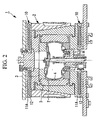
- a tire vulcanizer 1 shown in Fig. 2 is an apparatus which heats and vulcanizes a green tire T in a container (mold) 2.
- the container 2 is configured by including an outer mold (mold) 3 in which the green tire T is placed, and a bladder 4 which forms the inner space of the tire.
- outer mold 3 described above is divided into a plurality of members in order that the green tire T can be placed in the outer mold 3 and that the tire after vulcanization can be taken out from the outer mold 3.
- the outer mold 3, in which the green tire T is placed is heated, and also a high-temperature and high-pressure heating medium is supplied to the inside of the bladder 4 forming the inner space of the green tire T, so that the inner wall surface of the green tire T is pressed toward the outer mold 3 while being heated.
- a high-temperature and high-pressure heating medium is supplied to the inside of the bladder 4 forming the inner space of the green tire T, so that the inner wall surface of the green tire T is pressed toward the outer mold 3 while being heated.
- the inner and outer sides of the green tire T are heated by the heated outer mold 3 and the heating medium supplied to the inside of the bladder 4, and thereby the green tire T is vulcanized and molded.
- the green tire T placed in the outer mold 3 is heated by separate platens (heat plates) 10 respectively arranged on the upper and lower sides of the container 2, but the tire vulcanizer 1 may also have a structure in which the platen 10 is incorporated in the upper portion or the lower portion of the container 2.
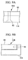
- the platen 10 is an electric platen formed by embedding a heat generating section 12, such as a rod-shaped heater and a planar heater, in a main body 11 having a doughnut-like disc shape. Note that, in the following description, the platen 10 arranged on the upper surface of the container 2 is exemplified.
- the basic structure of the platen is substantially the same as that of the platen arranged on the upper surface of the container 2, and only the upper and lower sides are reversed.
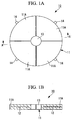
- the main body 11 is formed to have a circular shape, and a concentric through hole 13 is provided at the center portion of the main body 11. Further, the main body 11 of the platen 10 is divided into four sections at angular intervals of 90 degrees in the circumferential direction.
- each of the four sections formed by dividing the platen 10 in the circumferential direction is referred to as a divided platen 11A. That is, the four divided platens 11A, in each of which the independent heat generating section 12 is embedded, are connected to each other by concave-convex engaging sections 40 (see Fig. 5 ), and the like, in other words, the divided platens 11A, each of which has a substantially one-quarter circular shape and in each of which the heat generating section 12 is embedded, are integrally connected to each other, whereby the platen 10 shown in Fig 1A is formed into a doughnut-like disc shape, at the center portion of which the through hole 13 for centering is formed.
- reference numeral 14 in Fig. 1A denotes a flange section for connecting the platen 10 to the container 2, and the flange section is provided for each of the quadripartite divided platens 11A in the configuration example shown in Fig. 1A .
- the positioning accuracy of the divided platens 11A, which are integrally connected to each other to form the platen 10 having the through hole 13 used to center the installation position of the outer mold 3, is further improved by providing such flange sections 14.
- the platen 10 formed by connecting the divided platens 11A is arranged on each of the upper and lower sides of the container 2 in which the green tire T is placed. Therefore, at the time of vulcanization, the green tire T is heated, from the outside of the container 2 and of the outer mold 3, by the electric heat generating section 12 embedded in each of the divided platens 11A, and hence the platen 10 is hardly deformed even when receiving a load at the time of vulcanization. That is, the platen 10 is hardly deformed because of its structure divided in the circumferential direction, and hence a large stress is hardly generated in the platen 10.
- the number of division of the platen 10 in the circumferential direction is not limited to four described above, and the platen 10 may, of course, be bisected or trisected. Further, the platen 10 may also be divided into five sections or more according to the size, and the like, of the tire to be vulcanized.
- the platen 10 of the embodiment described above is formed into the doughnut-like disc shape by connecting the divided platens 11A quadrisected only in the circumferential direction.
- the platen 10 may also be divided into a plurality of sections in the radial direction in addition to the circumferential direction.
- the innermost section that is, the center side section, in which the through hole 13 is formed, is formed into a doughnut shape continuous in the circumferential direction.
- a platen 20 according to the first modification shown in Fig. 3 is specifically described.
- the platen 20 is configured such that an inner ring 22, in which the through hole 13 is formed, is left at the center portion of a main body 21 of the platen 20, and such that the outer circumferential side of the main body 21 is divided into four divided platens 21A in the circumferential direction. That is, the platen 20 shown in Fig. 3 has a divided structure in which the main body 21 is radially divided into the inner ring 22 and the four divided platens 21A divided in the circumferential direction. As a result, the platen 20, which is divided in the radial direction as well as in the circumferential direction, is more hardly deformed at the time of tire vulcanization.
- the inner ring 22 which is a divided platen having a doughnut-like disc-shape and formed at the innermost central portion of the platen 20, has the through hole 13 which is a small diameter hole formed at the center portion of the platen 20. Therefore, the through hole 13 can be used for centering the platen 20 at the time when the platen 20 is attached to the outer mold 3. That is, higher centering accuracy can be obtained by providing the inner ring 22 which is not divided in the circumferential direction.
- a platen 30 of a second modification shown in Fig. 4 is formed by also radially dividing the outer peripheral side of the platen 20 shown in Fig. 3 . That is, the platen 30 shown in Fig. 4 has a divided structure in which a main body 31 is radially divided into an inner ring 32, an outer ring 33, and four divided platens 31A divided in the circumferential direction. Note that the division in the radial direction is not limited to the division into the inner ring 32 and the outer ring 33, and may be suitably changed, for example, as in such a case where the divided platen 31A is also radially divided into a plurality of sections.
- the heat generating body of the outer ring 33 located on the outermost side of the platen 30 is not needed. Also, the kind of the heat generating body and the heating temperature can be suitably changed for each of the divided portions of the platens 30. Therefore, the design flexibility in the arrangement, selection, and the like, of the heat generating bodies can be increased.
- connection structures for connecting and positioning the mutually adjacent divided rings of the divided platens 11A, 21A and 31A, the inner rings 22 and 32, and the outer ring 33 which are formed by the division in the circumferential and radial directions. That is, examples of connection structures shown in the sectional views taken along lines B-B, C-C and D-D in Fig. 4 will be described with reference to the accompanying drawings.
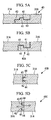
- Fig. 5A to Fig. 5D show structural examples of concave-convex engaging sections.
- Fig. 5A and Fig. 5B show structural examples in which the upper and lower surfaces at the end portions of the divided platens adjacent to each other are overlapped and engaged with each other.
- Fig. 5C and Fig. 5D show structural examples in which the end surfaces of the divided platens adjacent to each other are engaged with each other.
- Fig. 5A is a sectional view taken along line D-D in Fig. 4 and shows the concave-convex engaging section 40
- a concave section 41 and a convex section 42 which are engaged with each other in a manner of being vertically overlapped with each other, are respectively provided on the upper and lower surfaces of the divided platens 31A and 31A.
- the concave and convex sections 41 and 42 are respectively formed on mutually facing stepped surfaces 43 which are respectively provided at the end portions of the divided platens 31A and 31A.
- each of the front and back surfaces of the platen 30 having a disc shape maintains flatness, and the divided platens 31A and 31A are prevented from being horizontally moved (positionally deviated).
- each of the concave and convex sections 41 and 42 may be formed substantially at the center of each of stepped surfaces 43.
- the concave and convex sections 41 and 42 formed at the end portion of one of the divided platens 31A and 31A may be engaged with the concave and convex sections 41 and 42 formed at the end portion of the other of the divided platens 31A and 31A.
- the connection structure of the divided platens is not limited to the above-described structural examples, and the like.
- connection structure of the divided platens 31A and 31A adjacent to each other may also be configured as concave-convex engaging sections 40B and 40C in which one or plurality of concave and convex sections 45 and 46 are provided on the end surfaces 44 of the divided platens 31A and 31A so as to be engaged with each other in the horizontal direction.
- the side surfaces of the concave and convex sections 45 and 46 are slid in the horizontal direction so as to make the concave and convex sections 45 and 46 engage each other, and hence the divided platens 31A and 31A are prevented from being moved in the vertical direction.
- a fastening connecting section 50 shown in Fig. 6A has a structure in which stepped surfaces 51 and 52 are respectively formed at the end portions of the divided platens 31A and 31A adjacent to each other, and in which the stepped surfaces 51 and 52 are mechanically connected to each other by using a bolt 53 as a fastening member.
- a fastening connecting section 50A shown in Fig. 6B has a structure in which a concave-convex engaging section 54 is formed at the end portions of the divided platens 31A and 31A adjacent to each other, and in which the divided platens 31A and 31A are mechanically connected to each other by using a through-bolt 55, as a fastening member, passing through the concave-convex engaging section 54.
- the divided platens 31A and 31A are mechanically connected to each other by the fastening member, and hence the divided platens 31A and 31A can be integrated with each other by being positioned and surely connected to each other.
- a platen 10A shown in Fig. 7 has a structure in which the divided platens 11A of the platen 10 shown in Fig. 1B are integrated with each other by being connected and positioned by a plate-shaped member 60.
- a plate-shaped member 60 for example, a plate material having a continuous ring shape is used in correspondence with the doughnut-like disc shape of the platen 10A.
- the plate-shaped member 60 described above is, for example, as shown in Fig. 8A , connected to the divided platen 11A by a concave-convex engaging section 62 in a plate connecting section 61.
- the concave-convex engaging section 62 has a structure in which the concave and convex sections that are engaged with each other are respectively provided on the contact surfaces of the plate-shaped member 60 and the divided platen 11A, so as to be engaged with each other.
- the concave-convex engaging section 62 may be configured such that the concave section of the concave-convex engaging section 62 is provided on the plate-shaped member 60, and such that the convex section of the concave-convex engaging section 62 is provided on the divided platen 11A, or vice versa.
- a pair of the concave-convex engaging sections 62 may be respectively provided near the both ends of the divided platen 11A, or, for example, as shown in Fig. 8C , the concave-convex engaging section 62 may be provided at a position close to the center portion of the divided platen 11A.
- the plate-shaped member 60 described above may be, for example, as shown in Fig. 9A and Fig. 9B , positioned and connected with the divided platen 11A by using a fastening member, such as a bolt.
- the divided platen 11A and the plate-shaped member 60 are connected with each other by a bolt 63 extending in the vertical direction.
- the divided platen 11A and the plate-shaped member 60 are connected with each other by a bolt 64 extending in the horizontal direction.
- each of the platens 10, 20 and 30 may be divided into the plurality of divided platens of which the mutually adjacent divided platens 11A, 21A, and 31A and each of the inner rings 22 and 32 and the outer ring 33 are provided therebetween with two or more of the concave-convex engaging section 40, the fastening connecting section 50 and the plate connecting section 61. That is, in the platen formed by integrally connecting the plurality of divided platens to each other, a connection structure can be provided by suitably combining the concave-convex engaging section 40, the fastening connecting section 50, and the plate connecting section 61, and hence the positioning and connection between the divided platens can be easily performed by optimizing the connection structure.
- the platens 10, 20 and 30 respectively having the divided shapes are formed in such a manner that the electrical heating platen having the integrated disk shape is divided into the plurality of divided platens in the circumferential direction, and hence the following operation effects can be obtained.
- the tire vulcanizer 1 according to the embodiment described above can solve the problems of the electrical heating platen, which relate to the deformation at the time of tire vulcanization and to the replacement of the platen.
Description
- The present invention relates to a tire vulcanizer which vulcanizes and molds a green tire.
- Conventionally, in a tire vulcanizer which vulcanizes and molds a green tire, an outer mold (mold), in which the green tire is placed, is heated, and the inner wall surface of the green tire is pressed toward the outer mold while being heated by a high-temperature and high-pressure heating medium being supplied to the inner space of the green tire (to the inside of the bladder). Then, the outer side and the inner side of the green tire are heated by the heated outer mold and the heating medium supplied to the inner space of the green tire, and thereby the green tire is vulcanized.
- Note that the conventional tire vulcanizer is configured such that steam as a heating medium is supplied into and circulated through the inner space of the green tire; and such that a heated and pressurized medium, such as nitrogen gas and warm water, is sealed in the inner space.
- As a prior art of the tire vulcanizer described above, in which a green tire is heated from the outside thereof, there is an apparatus using a heat medium, as disclosed, for example, in
Patent Literatures 1 and 2. In the prior art, a platen (heat plate) is arranged on each of the upper and lower sides of an outer mold in which a green tire is placed, and steam as a heat medium is supplied to the inside of both the platens, so that heat is transferred to the green tire from the outside of the outer mold. - On the other hand, as for a tire vulcanizer in recent years, instead of the above-described heating technique using the heat medium, a heating technique using an electric platen has been proposed from the viewpoint of energy saving, and the like.
- As electric heating methods applied to the electric platen, there are known a heating method using a rod-shaped or planar electric heater embedded in the platen (see, for example,
Patent Literature 3 described below), and an induction heating method using an electromagnetic coil (see, for example, Patent Literature 4 described below). - Further, the conventional platen described above is formed into a one-piece structure having a doughnut-like disc shape, for facilitating the formation of a heat medium flow path, the attachment to the mold, and the like. However, Patent Literature 5 described below discloses a tire vulcanizing mold in which, in order to obtain a uniform degree of vulcanization over the whole of a tire, the platen is divided in the radial direction thereof, and the rates of temperature increase of heating sections are correspondingly changed.
-
- {PTL 1}
Japanese Unexamined Patent Application, Publication No.5-200754 - {PTL 2}
Japanese Unexamined Patent Application, Publication No.8-238626 - {PTL 3}
Japanese Unexamined Patent Application, Publication No.2002-36243 - {PTL 4}
Japanese Unexamined Patent Application, Publication No.2008-100513 - {PTL 5}
Japanese Unexamined Patent Application, Publication No.8-174554 - For example, as in an external view shown in
Fig. 10 , a conventional platen 5 of an electric heating type has a doughnut-like disc shape in the center portion of which a circular throughhole 6 is formed, and has a structure in which heat generating sections 7, such as rod-shaped heaters, are embedded. For this reason, in the case where a platen is changed to an electric platen from the viewpoint of energy saving, and the like, the following problems are caused because the platen 5 has the one-piece structure having the doughnut-like disc shape. - The first problem is that, at the time of tire vulcanization, deformation (deflection) is easily generated in the circular platen. For this reason, the life of a heat generating section, such as an electric heater, embedded in the platen, and the life of an attaching member, and the like, are reduced under the influence of the stress generated due to the deformation of the platen. Also, the deformation of the platen means that the contact area between the outer mold and the heat generating section is reduced, and hence the heat transfer property (heating efficiency) between the outer mold and the heat generating section is reduced. Further, when the heat transfer property between the outer mold and the heat generating section is reduced, the temperature of the heat generating section is increased to an unexpected high temperature, and thereby the thermal life of the heat generating section is reduced.
- The second problem relates to the replacement of the platen at the time of.maintenance, and the like, and is that, in the work of replacing the platen having the one-piece structure, much time is required for the removal of and the attachment and adjustment of the platen. Further, when the platen is replaced due to a failure, or the like, the entire platen must be collectively replaced, which is disadvantageous from the viewpoint of cost.
-
US-A-2024554 discloses a tire vulcanizer according to the preamble ofclaim 1. - The present invention has been made in view of the above described circumstances. An object of the present invention is to provide a tire vulcanizer capable of solving the problems of the electrical heating platen, which relate to the deformation at the time of tire vulcanization and to the replacement of the platen.
- The present invention adopts the following means in order to solve the above-described problems.
- A tire vulcanizer according to the present invention, as defined in
claim 1, which vulcanizes and molds a green tire placed in an outer mold by heating the green tire from the outside and the inside of the green tire, is featured by including an electric platen which is arranged to be in contact with each of the upper and lower sides of a container with the green tire placed therein, or to be embedded in each of the upper and lower portions of the container, so as to heat the green tire from the outside of the outer mold at the time of vulcanization, and which is formed into a doughnut-like disc shape and divided into a plurality of sections in the circumferential direction of the platen. - The tire vulcanizer according to the present invention includes the electric platen which is arranged to be in contact with each of the upper and lower sides of the container with a green tire placed therein, or to be embedded in each of the upper and lower portions of the container, so as to heat the green tire from the outside of the outer mold at the time of vulcanization, and which is formed into the doughnut-like disc shape and divided into the plurality of sections in the circumferential direction of the platen. Therefore, the platen is hardly deformed at the time of tire vulcanization.
- In the tire vulcanizer of the above-described invention, the platen is divided into a plurality of sections in the radial direction of the platen and is formed into a doughnut-like disc shape by connecting the innermost sides of the divided sections in the circumferential direction. Thereby, the platen is more hardly deformed at the time of tire vulcanization. In this case, the divided platens are connected and formed into the doughnut-like disc shape at the innermost center portion of the platen, and hence a small diameter hole is formed at the center portion of the platen, so that the hole can be used for the centering at the time of attaching the platen. Preferred embodiments of the invention are defined in the dependent claims.
- It is preferred that, in the tire vulcanizer of the above-described invention, the platen includes a concave-convex engaging section in which concave and convex sections of the mutually adjacent divided platens of the plurality of divided platens are engaged with each other to make the mutually adjacent divided platens connected together and positioned.
- Further, in the tire vulcanizer of the above-described invention, the platen may include a fastening connecting section in which the mutually adjacent divided platens of the plurality of divided platens are connected together and positioned by a fastening member.
- Further, in the tire vulcanizer of the above-described invention, the platen may be configured to include a plate connecting section in which the mutually adjacent divided platens of the plurality of divided platens are connected together and positioned via a plate-shaped member.
- Alternatively, in the tire vulcanizer of the above-described invention, the platen may be divided into a plurality of divided platens of which the mutually adjacent divided platens are provided therebetween with two or more of the concave-convex engaging section, the fastening connecting section and the plate connecting section.
- The mutually adjacent divided platens can be easily positioned and connected with each other by the concave-convex engaging section, the fastening connecting section, and the plate connecting section, and by a combination of the concave-convex engaging section, the fastening connecting section, and the plate connecting section.
- In the tire vulcanizer having the above-described configuration, the connection and positioning in the plate connecting section may be performed in such a manner that the concave-convex section provided on the upper surface or the lower surface of the platen is engaged with the concave-convex section provided on the lower surface or the upper surface of the plate-shaped member. Alternatively, in the plate connecting section, the platen and the plate-shaped member are connected together and positioned via a fastening member.
- According to the present invention described above, the electrical heating platen of the tire vulcanizer is configured to be divided into a plurality of sections in the circumferential direction, and hence the platen is hardly deformed by the load at the time of tire vulcanization, as a result of which the heating efficiency, the durability, and the reliability of the platen are improved. Further, the structure, in which the electrical heating platen is divided into a plurality of sections in the circumferential direction, facilitates the work of attaching and removing the platen and the work of replacing the platen, and hence is effective for improving the maintainability of the platen.
- Further, when the electrical heating platen is replaced, the replacement can be performed for each of the divided platens, and hence the cost required for replacing the components can be reduced.
- Further, the structure, in which the electrical heating platen is divided into a plurality of sections, enables an optimum division shape to be selected in correspondence with the structure of the vulcanizer, the tire mold, and the heating specification, and hence is effective for improving the degree of freedom of apparatus design. That is, since the electric heating method, in which a rod-shaped heater and a planar heater are combined together, can be easily used, and since the electric heating method and the heat-medium heating method are also easily combined together, the tire heating temperature can be made uniform and optimized. Thereby, the running cost for heating is reduced, and the accuracy of the heating temperature control is improved, as a result of which a tire vulcanizer capable of manufacturing a high quality tire is provided.
-
- {
Fig. 1A }
Fig. 1A is a plan view showing a structure of a platen (heat plate) as an embodiment of a tire vulcanizer according to the present invention. - {
Fig. 1B }
Fig. 1B is a view showing the structure of the platen (heat plate) as the embodiment of the tire vulcanizer according to the present invention, and is a longitudinal sectional view (sectional view taken along line A-A) inFig. 1A . - {
Fig. 2 }
Fig. 2 is a longitudinal sectional view showing a configuration example of a tire vulcanizer provided with the platen shown inFig. 1 . - {
Fig. 3 }
Fig. 3 is a plan view showing a first modification of the platen shown inFig. 1 . - {
Fig. 4 }
Fig. 4 is a plan view showing a second modification of the platen shown inFig. 1 . - {
Fig. 5A }
Fig. 5A is a view showing a structural example of a concave-convex engaging section, and showing a structural example in which the upper and lower surfaces of the divided platens adjacent to each other are overlapped and engaged with each other at the end portions of the divided platens. - {
Fig. 5B }
Fig. 5B is a view showing a structural example of a concave-convex engaging section, and showing a structural example in which the upper and lower surfaces of the divided platens adjacent to each other are overlapped and engaged with each other at the end portions of the divided platens. - {
Fig. 5C }
Fig. 5C is a view showing a structural example of a concave-convex engaging section, and showing a structural example in which the end surfaces of the divided platens adjacent to each other are engaged with each other. - {
Fig. 5D }
Fig. 5D is a view showing a structural example of a concave-convex engaging section, and showing a structural example in which the end surfaces of the divided platens adjacent to each other are engaged with each other. - {
Fig. 6A }
Fig. 6A is a view showing a structural example of a fastening connecting section, and showing a structural example in which concave-convex surfaces formed at the end portions of the divided platens adjacent to each other are vertically overlapped and fastened together by a bolt. - {
Fig. 6B }
Fig. 6B is a view showing a structural example of a fastening connecting section, and showing a structural example in which concave and convex portions formed at the end portions of the divided platens adjacent to each other are engaged and fastened together by a through-bolt. - {
Fig. 7 }
Fig. 7 is a front view showing an appearance of a platen formed by connecting divided platens to each other via a plate-shaped member. - {
Fig. 8A }
Fig. 8A is a view showing a structural example of a plate connecting section, and is a longitudinal sectional view showing an example of a plate connecting section. - {
Fig. 8B }
Fig. 8B is a view showing a structural example of a plate connecting section, and is a plan view showing an arrangement example of concave-convex sections of a divided platen. - {
Fig. 8C }
Fig. 8C is a view showing a structural example of a plate connecting section, and is a plan view showing an arrangement example of a concave-convex section of a divided platen. - {
Fig. 9A }
Fig. 9A is a view showing a structural example of a plate connecting section, and showing a structural example in which a divided platen and a plate-shaped member are fastened by a vertical bolt. - {
Fig. 9B }
Fig. 9B is a view showing a structural example of a plate connecting section, and showing a structural example in which a divided platen and a plate-shaped member are fastened by a horizontal bolt. - {
Fig. 10A }
Fig. 10A is a plan view showing an appearance of a platen used for a tire vulcanizer. - {
Fig. 10B }
Fig. 10B is a view showing an appearance of the platen used for the tire vulcanizer, and is a front view ofFig. 10A . - In the following, an embodiment of a tire vulcanizer according to the present invention will be described with reference to the accompanying drawings.
- A
tire vulcanizer 1 shown inFig. 2 is an apparatus which heats and vulcanizes a green tire T in a container (mold) 2. The container 2 is configured by including an outer mold (mold) 3 in which the green tire T is placed, and a bladder 4 which forms the inner space of the tire. - Note that the
outer mold 3 described above is divided into a plurality of members in order that the green tire T can be placed in theouter mold 3 and that the tire after vulcanization can be taken out from theouter mold 3. - In the
tire vulcanizer 1, theouter mold 3, in which the green tire T is placed, is heated, and also a high-temperature and high-pressure heating medium is supplied to the inside of the bladder 4 forming the inner space of the green tire T, so that the inner wall surface of the green tire T is pressed toward theouter mold 3 while being heated. As a result, the inner and outer sides of the green tire T are heated by the heatedouter mold 3 and the heating medium supplied to the inside of the bladder 4, and thereby the green tire T is vulcanized and molded. - In the case of the
tire vulcanizer 1 shown inFig. 2 , the green tire T placed in theouter mold 3 is heated by separate platens (heat plates) 10 respectively arranged on the upper and lower sides of the container 2, but thetire vulcanizer 1 may also have a structure in which theplaten 10 is incorporated in the upper portion or the lower portion of the container 2. Theplaten 10 is an electric platen formed by embedding aheat generating section 12, such as a rod-shaped heater and a planar heater, in amain body 11 having a doughnut-like disc shape. Note that, in the following description, theplaten 10 arranged on the upper surface of the container 2 is exemplified. However, when theplaten 10 is arranged on the lower surface of the container 2 or when theplaten 10 is incorporated in the container 2, the basic structure of the platen is substantially the same as that of the platen arranged on the upper surface of the container 2, and only the upper and lower sides are reversed. - In the
platen 10 having the doughnut-like disc shape shown inFig. 1A , themain body 11 is formed to have a circular shape, and a concentric throughhole 13 is provided at the center portion of themain body 11. Further, themain body 11 of theplaten 10 is divided into four sections at angular intervals of 90 degrees in the circumferential direction. - In the following description, each of the four sections formed by dividing the
platen 10 in the circumferential direction is referred to as a dividedplaten 11A. That is, the four dividedplatens 11A, in each of which the independentheat generating section 12 is embedded, are connected to each other by concave-convex engaging sections 40 (seeFig. 5 ), and the like, in other words, the dividedplatens 11A, each of which has a substantially one-quarter circular shape and in each of which theheat generating section 12 is embedded, are integrally connected to each other, whereby theplaten 10 shown inFig 1A is formed into a doughnut-like disc shape, at the center portion of which the throughhole 13 for centering is formed. - Further,
reference numeral 14 inFig. 1A denotes a flange section for connecting theplaten 10 to the container 2, and the flange section is provided for each of the quadripartite dividedplatens 11A in the configuration example shown inFig. 1A . The positioning accuracy of the dividedplatens 11A, which are integrally connected to each other to form theplaten 10 having the throughhole 13 used to center the installation position of theouter mold 3, is further improved by providingsuch flange sections 14. - In the
tire vulcanizer 1 configured in this way, theplaten 10 formed by connecting the dividedplatens 11A is arranged on each of the upper and lower sides of the container 2 in which the green tire T is placed. Therefore, at the time of vulcanization, the green tire T is heated, from the outside of the container 2 and of theouter mold 3, by the electricheat generating section 12 embedded in each of the dividedplatens 11A, and hence theplaten 10 is hardly deformed even when receiving a load at the time of vulcanization. That is, theplaten 10 is hardly deformed because of its structure divided in the circumferential direction, and hence a large stress is hardly generated in theplaten 10. - Note that the number of division of the
platen 10 in the circumferential direction is not limited to four described above, and theplaten 10 may, of course, be bisected or trisected. Further, theplaten 10 may also be divided into five sections or more according to the size, and the like, of the tire to be vulcanized. - Meanwhile, the
platen 10 of the embodiment described above is formed into the doughnut-like disc shape by connecting the dividedplatens 11A quadrisected only in the circumferential direction. However, as in a first modification shown inFig. 3 , and a second modification shown inFig. 4 , theplaten 10 may also be divided into a plurality of sections in the radial direction in addition to the circumferential direction. - In this case, it is preferred that the innermost section, that is, the center side section, in which the through
hole 13 is formed, is formed into a doughnut shape continuous in the circumferential direction. - In the following, a
platen 20 according to the first modification shown inFig. 3 is specifically described. Theplaten 20 is configured such that aninner ring 22, in which the throughhole 13 is formed, is left at the center portion of amain body 21 of theplaten 20, and such that the outer circumferential side of themain body 21 is divided into four dividedplatens 21A in the circumferential direction. That is, theplaten 20 shown inFig. 3 has a divided structure in which themain body 21 is radially divided into theinner ring 22 and the four dividedplatens 21A divided in the circumferential direction. As a result, theplaten 20, which is divided in the radial direction as well as in the circumferential direction, is more hardly deformed at the time of tire vulcanization. - Further, the
inner ring 22, which is a divided platen having a doughnut-like disc-shape and formed at the innermost central portion of theplaten 20, has the throughhole 13 which is a small diameter hole formed at the center portion of theplaten 20. Therefore, the throughhole 13 can be used for centering theplaten 20 at the time when theplaten 20 is attached to theouter mold 3. That is, higher centering accuracy can be obtained by providing theinner ring 22 which is not divided in the circumferential direction. - Further, a platen 30 of a second modification shown in
Fig. 4 is formed by also radially dividing the outer peripheral side of theplaten 20 shown inFig. 3 . That is, the platen 30 shown inFig. 4 has a divided structure in which amain body 31 is radially divided into aninner ring 32, anouter ring 33, and four dividedplatens 31A divided in the circumferential direction. Note that the division in the radial direction is not limited to the division into theinner ring 32 and theouter ring 33, and may be suitably changed, for example, as in such a case where the dividedplaten 31A is also radially divided into a plurality of sections. - In this structure, in the case where the diameter of the platen 30 is larger than the container 2, the heat generating body of the
outer ring 33 located on the outermost side of the platen 30 is not needed. Also, the kind of the heat generating body and the heating temperature can be suitably changed for each of the divided portions of the platens 30. Therefore, the design flexibility in the arrangement, selection, and the like, of the heat generating bodies can be increased. - Subsequently, there will be described connection structures for connecting and positioning the mutually adjacent divided rings of the divided
platens inner rings outer ring 33, which are formed by the division in the circumferential and radial directions. That is, examples of connection structures shown in the sectional views taken along lines B-B, C-C and D-D inFig. 4 will be described with reference to the accompanying drawings. -
Fig. 5A to Fig. 5D show structural examples of concave-convex engaging sections.Fig. 5A and Fig. 5B show structural examples in which the upper and lower surfaces at the end portions of the divided platens adjacent to each other are overlapped and engaged with each other.Fig. 5C and Fig. 5D show structural examples in which the end surfaces of the divided platens adjacent to each other are engaged with each other. - Here, in the case where
Fig. 5A is a sectional view taken along line D-D inFig. 4 and shows the concave-convexengaging section 40, aconcave section 41 and aconvex section 42, which are engaged with each other in a manner of being vertically overlapped with each other, are respectively provided on the upper and lower surfaces of the dividedplatens convex sections surfaces 43 which are respectively provided at the end portions of the dividedplatens convex sections platens - As described above, each of the concave and
convex sections engaging section 40A shown inFig. 5B , the concave andconvex sections platens convex sections platens - Further, as shown in
Fig. 5C and Fig. 5D , the connection structure of the dividedplatens engaging sections platens platens - Next, structural examples of fastening connecting sections shown in
Fig. 6A and Fig. 6B will be described. - A
fastening connecting section 50 shown inFig. 6A has a structure in which stepped surfaces 51 and 52 are respectively formed at the end portions of the dividedplatens bolt 53 as a fastening member. Further, afastening connecting section 50A shown inFig. 6B has a structure in which a concave-convexengaging section 54 is formed at the end portions of the dividedplatens platens bolt 55, as a fastening member, passing through the concave-convexengaging section 54. - When such
fastening connecting sections platens platens - Finally, structural examples of plate connecting sections shown in
Fig. 7 to Fig. 9 will be described. - A
platen 10A shown inFig. 7 has a structure in which the dividedplatens 11A of theplaten 10 shown inFig. 1B are integrated with each other by being connected and positioned by a plate-shapedmember 60. In this case, as the plate-shapedmember 60, for example, a plate material having a continuous ring shape is used in correspondence with the doughnut-like disc shape of theplaten 10A. - The plate-shaped
member 60 described above is, for example, as shown inFig. 8A , connected to the dividedplaten 11A by a concave-convexengaging section 62 in aplate connecting section 61. The concave-convexengaging section 62 has a structure in which the concave and convex sections that are engaged with each other are respectively provided on the contact surfaces of the plate-shapedmember 60 and the dividedplaten 11A, so as to be engaged with each other. In this case, the concave-convexengaging section 62 may be configured such that the concave section of the concave-convexengaging section 62 is provided on the plate-shapedmember 60, and such that the convex section of the concave-convexengaging section 62 is provided on the divided platen 11A, or vice versa. - Further, as for the position of the concave-convex
engaging section 62, for example, as shown inFig. 8B , a pair of the concave-convexengaging sections 62 may be respectively provided near the both ends of the divided platen 11A, or, for example, as shown inFig. 8C , the concave-convexengaging section 62 may be provided at a position close to the center portion of the dividedplaten 11A. - Further, the plate-shaped
member 60 described above may be, for example, as shown inFig. 9A and Fig. 9B , positioned and connected with the dividedplaten 11A by using a fastening member, such as a bolt. - In a structural example of the
plate connecting section 61A shown inFig. 9A , the dividedplaten 11A and the plate-shapedmember 60 are connected with each other by abolt 63 extending in the vertical direction. In a structural example of aplate connecting section 61B shown inFig. 9B , the dividedplaten 11A and the plate-shapedmember 60 are connected with each other by abolt 64 extending in the horizontal direction. - In the
tire vulcanizer 1 described above, each of theplatens platens inner rings outer ring 33 are provided therebetween with two or more of the concave-convexengaging section 40, thefastening connecting section 50 and theplate connecting section 61. That is, in the platen formed by integrally connecting the plurality of divided platens to each other, a connection structure can be provided by suitably combining the concave-convexengaging section 40, thefastening connecting section 50, and theplate connecting section 61, and hence the positioning and connection between the divided platens can be easily performed by optimizing the connection structure. - In this way, in the
tire vulcanizer 1 according to the present embodiment described above, theplatens - 1) The platen is hardly deformed (deflected) at the time of tire vulcanization, and hence the lives of the heat generating section, the attaching members (for example, a flange section, an upper and lower plates, and a fastening member, such as a bolt), and the like, are improved.
- 2) With the platen which is hardly deformed, the contact area between the platen and the heat generating section is hardly changed, and hence the heat transfer property is not lowered, as a result of which an excellent heating efficiency is obtained and also the thermal life of the heat generating section is improved.
- 3) When the platen is replaced, the platen can be easily removed and can be easily attached and adjusted, and hence the maintainability is improved.
- 4) The platen, a part of which can be replaced for each of the divided platens, is effective to reduce the cost.
- 5) An optimum division shape of the platen can be selected in correspondence with the structure of a tire vulcanizer, the mold structure of a container, and heating specifications.
- 6) In the platen, a combination of different kinds of electric heating methods, such as a method using an electric heater (including a combination of a rod-shaped heater and a planar heater) and an induction heating method, or a combination of the electric heating method and a heat-medium heating method can be easily used for each divided platen.
- In this way, the
tire vulcanizer 1 according to the embodiment described above can solve the problems of the electrical heating platen, which relate to the deformation at the time of tire vulcanization and to the replacement of the platen. - Note that the present invention is not limited to the above described embodiment, and can be suitably modified within the scope and spirit of the present invention.
- 1 Tire vulcanizer 2 Container (mold) 3 Outer mold (mold) 4
Bladder Platen platen 12Heat generating body 13 Throughhole 14Flange section 40 Concave-convexengaging section 50Fastening connecting section 60 Plate-shapedmember 61 Plate connecting section
Claims (7)
- A tire vulcanizer (1) which vulcanizes and molds a green tire (T) placed in an outer mold (2) by heating the green tire (T) from the outer side and the inner side of the green tire, the tire vulcanizer (1) comprising an electric platen (10) which is arranged to be In contact with each of the upper and lower sides of a container (2) with the green tire (T) placed therein, or to be embedded in each of the upper and lower portions of the container (2), so as to heat the green tire from the outside of the outer mold (3) at the time of vulcanization, and is formed into a doughnut-like disc shape and divided into a plurality of sections (11A) in the circumferential direction of the platen, characterized in that the platen is divided into a plurality of sections in the radial direction and is formed into a doughnut-like disc shape by mutually connecting the innermost sides of the divided sections (11A) in the circumferential direction.
- The tire vulcanizer according to claim 1, wherein the platen (10) includes a concave-convex engaging section (40) in which concave and convex sections of the mutually adjacent divided platens of the plurality of divided platens are connected to each other and positioned by being engaged with each other.
- The tire vulcanizer according to claim 1, wherein the platen includes a fastening connecting section (50) in which the mutually adjacent divided platens of the plurality of divided platens are connected to each other and positioned by a fastening member (55).
- The tire vulcanizer according to claim 1, wherein the platen includes a plate connecting section in which the mutually adjacent divided platens of the plurality of divided platens are connected to each other and positioned via a plate-shaped member.
- The tire vulcanizer aacording to claim 1 wherein the platen is divided into a plurality of divided platens of which the mutually adjacent divided platens are provided therebetween with two or more sections selected from the group consisting of:- a concave-convex engaging section (40) in which concave and convex sections of the mutually adjacent divided platens of the plurality of divided platens are connected to each other and positioned by being engaged with each other;- a fastening connecting section (50) in which the mutually adjacent divided platens of the plurality of divided platens are connected to each other and positioned by a fastening member (55); and- a plate connecting section in which the mutually adjacent divided platens of the plurality of divided platens are connected to each other and positioned via a plate-shaped member.
- The tire vulcanizer according to claim 5, wherein the connection and positioning in the plate connecting section are performed in such a manner that the concave-convex section provided on the upper surface or the lower surface of the platen is engaged with the concave-convex section provided on the lower surface or the upper surface of the plate-shaped member.
- The tire vulcanizer according to claim 6, wherein, in the plate connecting section, the divided platen and the plate-shaped member are connected to each other and positioned via a fastening member.
Priority Applications (1)
| Application Number | Priority Date | Filing Date | Title |
|---|---|---|---|
| HRP20170048TT HRP20170048T1 (en) | 2011-02-25 | 2017-01-12 | Tire vulcanization device |
Applications Claiming Priority (2)
| Application Number | Priority Date | Filing Date | Title |
|---|---|---|---|
| JP2011040720A JP5725906B2 (en) | 2011-02-25 | 2011-02-25 | Tire vulcanizer |
| PCT/JP2011/060741 WO2012114542A1 (en) | 2011-02-25 | 2011-05-10 | Tire vulcanization device |
Publications (3)
| Publication Number | Publication Date |
|---|---|
| EP2679367A1 EP2679367A1 (en) | 2014-01-01 |
| EP2679367A4 EP2679367A4 (en) | 2014-02-19 |
| EP2679367B1 true EP2679367B1 (en) | 2016-10-19 |
Family
ID=46720353
Family Applications (1)
| Application Number | Title | Priority Date | Filing Date |
|---|---|---|---|
| EP11817288.1A Not-in-force EP2679367B1 (en) | 2011-02-25 | 2011-05-10 | Tire vulcanization device |
Country Status (8)
| Country | Link |
|---|---|
| US (1) | US8591212B2 (en) |
| EP (1) | EP2679367B1 (en) |
| JP (1) | JP5725906B2 (en) |
| KR (1) | KR101356815B1 (en) |
| CN (1) | CN102869486B (en) |
| HR (1) | HRP20170048T1 (en) |
| TW (1) | TWI428227B (en) |
| WO (1) | WO2012114542A1 (en) |
Families Citing this family (2)
| Publication number | Priority date | Publication date | Assignee | Title |
|---|---|---|---|---|
| JP2015020331A (en) | 2013-07-18 | 2015-02-02 | 株式会社ジェイテクト | Rubber vulcanizing apparatus and vulcanizing method |
| JP5944052B2 (en) * | 2014-02-07 | 2016-07-05 | 三菱重工マシナリーテクノロジー株式会社 | Mold heating device, tire vulcanizer |
Family Cites Families (16)
| Publication number | Priority date | Publication date | Assignee | Title |
|---|---|---|---|---|
| US1682620A (en) * | 1922-01-10 | 1928-08-28 | Budd Edward G Mfg Co | Apparatus for electrical vulcanizing |
| US2024554A (en) * | 1933-01-03 | 1935-12-17 | Vogt Leslie Thomas | Apparatus for vulcanizing tires and other articles |
| US2456063A (en) * | 1944-07-24 | 1948-12-14 | Harold V James | Tire retreading device |
| IT1189673B (en) * | 1986-05-20 | 1988-02-04 | Firestone Int Dev Spa | TIRE VULCANIZATION SYSTEM |
| JPH0353855Y2 (en) * | 1988-11-17 | 1991-11-26 | ||
| JP2505675B2 (en) | 1992-01-24 | 1996-06-12 | 三菱重工業株式会社 | Tire vulcanizing press |
| IT1257245B (en) * | 1992-07-01 | 1996-01-10 | Firestone Int Dev Spa | VULCANIZATION REACTOR FOR TIRES OF ROAD VEHICLES. |
| JPH08174554A (en) * | 1994-12-20 | 1996-07-09 | Sumitomo Rubber Ind Ltd | Tire vulcanizing mold apparatus |
| JP3254097B2 (en) | 1995-03-07 | 2002-02-04 | 三菱重工業株式会社 | Mold assembly for tire vulcanization |
| JP2001079851A (en) * | 1999-09-17 | 2001-03-27 | Kobe Steel Ltd | Vulcanizer |
| JP3828726B2 (en) | 2000-07-31 | 2006-10-04 | 株式会社神戸製鋼所 | Vulcanizer |
| CN100513115C (en) * | 2005-03-26 | 2009-07-15 | 桂林橡胶机械厂 | Vulcanization mechanical electrical heating device |
| CN101100094A (en) * | 2006-07-05 | 2008-01-09 | 天津市橡塑机械研究所有限公司 | Giant engineering tyre hydraulic tank type vulcanizing device |
| WO2008035783A1 (en) * | 2006-09-21 | 2008-03-27 | Kabushiki Kaisha Kobe Seiko Sho | Heating unit, tire heating device, and tire mold modifying method |
| JP4786620B2 (en) | 2006-09-21 | 2011-10-05 | 株式会社神戸製鋼所 | Heating unit and tire heating device |
| JP5362263B2 (en) * | 2008-06-20 | 2013-12-11 | 住友ゴム工業株式会社 | Tire vulcanizer |
-
2011
- 2011-02-25 JP JP2011040720A patent/JP5725906B2/en active Active
- 2011-05-10 US US13/391,612 patent/US8591212B2/en not_active Expired - Fee Related
- 2011-05-10 CN CN201180003486.9A patent/CN102869486B/en not_active Expired - Fee Related
- 2011-05-10 KR KR1020127004462A patent/KR101356815B1/en active IP Right Grant
- 2011-05-10 WO PCT/JP2011/060741 patent/WO2012114542A1/en active Application Filing
- 2011-05-10 EP EP11817288.1A patent/EP2679367B1/en not_active Not-in-force
- 2011-06-28 TW TW100122611A patent/TWI428227B/en not_active IP Right Cessation
-
2017
- 2017-01-12 HR HRP20170048TT patent/HRP20170048T1/en unknown
Non-Patent Citations (1)
| Title |
|---|
| None * |
Also Published As
| Publication number | Publication date |
|---|---|
| CN102869486A (en) | 2013-01-09 |
| TWI428227B (en) | 2014-03-01 |
| EP2679367A4 (en) | 2014-02-19 |
| TW201235182A (en) | 2012-09-01 |
| JP5725906B2 (en) | 2015-05-27 |
| JP2012176552A (en) | 2012-09-13 |
| HRP20170048T1 (en) | 2017-03-10 |
| CN102869486B (en) | 2015-06-17 |
| US20130017287A1 (en) | 2013-01-17 |
| KR20120139658A (en) | 2012-12-27 |
| US8591212B2 (en) | 2013-11-26 |
| KR101356815B1 (en) | 2014-01-28 |
| EP2679367A1 (en) | 2014-01-01 |
| WO2012114542A1 (en) | 2012-08-30 |
Similar Documents
| Publication | Publication Date | Title |
|---|---|---|
| JP5944052B2 (en) | Mold heating device, tire vulcanizer | |
| EP2679367B1 (en) | Tire vulcanization device | |
| CN101462318A (en) | Tire mold | |
| US20120111464A1 (en) | Method for manufacturing base tire, curing machine, and base tire | |
| JP6123753B2 (en) | Electromagnetic induction heating mold equipment for molding and vulcanization of rubber packing | |
| CN101578166A (en) | Tire vulcanizer | |
| EP4134582A1 (en) | Fluid vessel and manufacturing method for a fluid vessel | |
| JP2006231931A (en) | Vulcanizing system and its green tire heating method | |
| CN102837382B (en) | Rigid core for building | |
| JP2013006390A (en) | Rigid core and method for producing tire by using the same | |
| US20160375644A1 (en) | Mold with sectros for a tire including insulating supporting plates, and associated molding method | |
| CN108000913A (en) | A kind of heat stepwise tire-mold | |
| US20190009434A1 (en) | Vulcanizing Mould With Enhanced Sealing | |
| CN210651521U (en) | Tire mold | |
| KR101796030B1 (en) | Pressurization apparatus for preventing faulty formation pattern of tire | |
| CN113815157B (en) | Electric heating die for integrally forming rubber tire | |
| CN107206638A (en) | Tire preheating device, tire vulcanizing system, tire pre-heating mean and tire manufacturing method | |
| JP7207005B2 (en) | tire vulcanizer | |
| CN218505293U (en) | Vulcanizing equipment | |
| CN116619802B (en) | Tire mold and tire vulcanizing device | |
| JP2017217781A (en) | Container for vulcanizing tire | |
| JP6809033B2 (en) | Tire vulcanization container | |
| US9138950B2 (en) | Tire molding apparatus | |
| KR0136441Y1 (en) | Position of a mold for vulcanizing a tire | |
| JP2012040803A (en) | Method for manufacturing tire |
Legal Events
| Date | Code | Title | Description |
|---|---|---|---|
| PUAI | Public reference made under article 153(3) epc to a published international application that has entered the european phase |
Free format text: ORIGINAL CODE: 0009012 |
|
| 17P | Request for examination filed |
Effective date: 20120221 |
|
| AK | Designated contracting states |
Kind code of ref document: A1 Designated state(s): AL AT BE BG CH CY CZ DE DK EE ES FI FR GB GR HR HU IE IS IT LI LT LU LV MC MK MT NL NO PL PT RO RS SE SI SK SM TR |
|
| A4 | Supplementary search report drawn up and despatched |
Effective date: 20140121 |
|
| RIC1 | Information provided on ipc code assigned before grant |
Ipc: B29C 33/02 20060101AFI20140115BHEP Ipc: B29D 30/06 20060101ALI20140115BHEP Ipc: B29C 35/02 20060101ALI20140115BHEP |
|
| DAX | Request for extension of the european patent (deleted) | ||
| 17Q | First examination report despatched |
Effective date: 20151113 |
|
| GRAP | Despatch of communication of intention to grant a patent |
Free format text: ORIGINAL CODE: EPIDOSNIGR1 |
|
| INTG | Intention to grant announced |
Effective date: 20160422 |
|
| GRAS | Grant fee paid |
Free format text: ORIGINAL CODE: EPIDOSNIGR3 |
|
| GRAJ | Information related to disapproval of communication of intention to grant by the applicant or resumption of examination proceedings by the epo deleted |
Free format text: ORIGINAL CODE: EPIDOSDIGR1 |
|
| GRAL | Information related to payment of fee for publishing/printing deleted |
Free format text: ORIGINAL CODE: EPIDOSDIGR3 |
|
| GRAR | Information related to intention to grant a patent recorded |
Free format text: ORIGINAL CODE: EPIDOSNIGR71 |
|
| GRAA | (expected) grant |
Free format text: ORIGINAL CODE: 0009210 |
|
| INTC | Intention to grant announced (deleted) | ||
| INTG | Intention to grant announced |
Effective date: 20160905 |
|
| AK | Designated contracting states |
Kind code of ref document: B1 Designated state(s): AL AT BE BG CH CY CZ DE DK EE ES FI FR GB GR HR HU IE IS IT LI LT LU LV MC MK MT NL NO PL PT RO RS SE SI SK SM TR |
|
| REG | Reference to a national code |
Ref country code: GB Ref legal event code: FG4D |
|
| REG | Reference to a national code |
Ref country code: CH Ref legal event code: EP |
|
| REG | Reference to a national code |
Ref country code: AT Ref legal event code: REF Ref document number: 837939 Country of ref document: AT Kind code of ref document: T Effective date: 20161115 |
|
| REG | Reference to a national code |
Ref country code: IE Ref legal event code: FG4D |
|
| REG | Reference to a national code |
Ref country code: DE Ref legal event code: R096 Ref document number: 602011031542 Country of ref document: DE |
|
| REG | Reference to a national code |
Ref country code: RO Ref legal event code: EPE |
|
| REG | Reference to a national code |
Ref country code: HR Ref legal event code: TUEP Ref document number: P20170048 Country of ref document: HR |
|
| REG | Reference to a national code |
Ref country code: NL Ref legal event code: MP Effective date: 20161019 |
|
| REG | Reference to a national code |
Ref country code: LT Ref legal event code: MG4D |
|
| PG25 | Lapsed in a contracting state [announced via postgrant information from national office to epo] |
Ref country code: LV Free format text: LAPSE BECAUSE OF FAILURE TO SUBMIT A TRANSLATION OF THE DESCRIPTION OR TO PAY THE FEE WITHIN THE PRESCRIBED TIME-LIMIT Effective date: 20161019 |
|
| REG | Reference to a national code |
Ref country code: HR Ref legal event code: T1PR Ref document number: P20170048 Country of ref document: HR |
|
| REG | Reference to a national code |
Ref country code: AT Ref legal event code: MK05 Ref document number: 837939 Country of ref document: AT Kind code of ref document: T Effective date: 20161019 |
|
| PG25 | Lapsed in a contracting state [announced via postgrant information from national office to epo] |
Ref country code: LT Free format text: LAPSE BECAUSE OF FAILURE TO SUBMIT A TRANSLATION OF THE DESCRIPTION OR TO PAY THE FEE WITHIN THE PRESCRIBED TIME-LIMIT Effective date: 20161019 Ref country code: NO Free format text: LAPSE BECAUSE OF FAILURE TO SUBMIT A TRANSLATION OF THE DESCRIPTION OR TO PAY THE FEE WITHIN THE PRESCRIBED TIME-LIMIT Effective date: 20170119 Ref country code: SE Free format text: LAPSE BECAUSE OF FAILURE TO SUBMIT A TRANSLATION OF THE DESCRIPTION OR TO PAY THE FEE WITHIN THE PRESCRIBED TIME-LIMIT Effective date: 20161019 Ref country code: GR Free format text: LAPSE BECAUSE OF FAILURE TO SUBMIT A TRANSLATION OF THE DESCRIPTION OR TO PAY THE FEE WITHIN THE PRESCRIBED TIME-LIMIT Effective date: 20170120 |
|
| REG | Reference to a national code |
Ref country code: FR Ref legal event code: PLFP Year of fee payment: 7 |
|
| PG25 | Lapsed in a contracting state [announced via postgrant information from national office to epo] |
Ref country code: IS Free format text: LAPSE BECAUSE OF FAILURE TO SUBMIT A TRANSLATION OF THE DESCRIPTION OR TO PAY THE FEE WITHIN THE PRESCRIBED TIME-LIMIT Effective date: 20170219 Ref country code: NL Free format text: LAPSE BECAUSE OF FAILURE TO SUBMIT A TRANSLATION OF THE DESCRIPTION OR TO PAY THE FEE WITHIN THE PRESCRIBED TIME-LIMIT Effective date: 20161019 Ref country code: PL Free format text: LAPSE BECAUSE OF FAILURE TO SUBMIT A TRANSLATION OF THE DESCRIPTION OR TO PAY THE FEE WITHIN THE PRESCRIBED TIME-LIMIT Effective date: 20161019 Ref country code: PT Free format text: LAPSE BECAUSE OF FAILURE TO SUBMIT A TRANSLATION OF THE DESCRIPTION OR TO PAY THE FEE WITHIN THE PRESCRIBED TIME-LIMIT Effective date: 20170220 Ref country code: BE Free format text: LAPSE BECAUSE OF FAILURE TO SUBMIT A TRANSLATION OF THE DESCRIPTION OR TO PAY THE FEE WITHIN THE PRESCRIBED TIME-LIMIT Effective date: 20161019 Ref country code: AT Free format text: LAPSE BECAUSE OF FAILURE TO SUBMIT A TRANSLATION OF THE DESCRIPTION OR TO PAY THE FEE WITHIN THE PRESCRIBED TIME-LIMIT Effective date: 20161019 Ref country code: ES Free format text: LAPSE BECAUSE OF FAILURE TO SUBMIT A TRANSLATION OF THE DESCRIPTION OR TO PAY THE FEE WITHIN THE PRESCRIBED TIME-LIMIT Effective date: 20161019 Ref country code: RS Free format text: LAPSE BECAUSE OF FAILURE TO SUBMIT A TRANSLATION OF THE DESCRIPTION OR TO PAY THE FEE WITHIN THE PRESCRIBED TIME-LIMIT Effective date: 20161019 Ref country code: FI Free format text: LAPSE BECAUSE OF FAILURE TO SUBMIT A TRANSLATION OF THE DESCRIPTION OR TO PAY THE FEE WITHIN THE PRESCRIBED TIME-LIMIT Effective date: 20161019 |
|
| REG | Reference to a national code |
Ref country code: DE Ref legal event code: R097 Ref document number: 602011031542 Country of ref document: DE |
|
| PG25 | Lapsed in a contracting state [announced via postgrant information from national office to epo] |
Ref country code: SK Free format text: LAPSE BECAUSE OF FAILURE TO SUBMIT A TRANSLATION OF THE DESCRIPTION OR TO PAY THE FEE WITHIN THE PRESCRIBED TIME-LIMIT Effective date: 20161019 Ref country code: DK Free format text: LAPSE BECAUSE OF FAILURE TO SUBMIT A TRANSLATION OF THE DESCRIPTION OR TO PAY THE FEE WITHIN THE PRESCRIBED TIME-LIMIT Effective date: 20161019 Ref country code: EE Free format text: LAPSE BECAUSE OF FAILURE TO SUBMIT A TRANSLATION OF THE DESCRIPTION OR TO PAY THE FEE WITHIN THE PRESCRIBED TIME-LIMIT Effective date: 20161019 |
|
| PLBE | No opposition filed within time limit |
Free format text: ORIGINAL CODE: 0009261 |
|
| STAA | Information on the status of an ep patent application or granted ep patent |
Free format text: STATUS: NO OPPOSITION FILED WITHIN TIME LIMIT |
|
| PG25 | Lapsed in a contracting state [announced via postgrant information from national office to epo] |
Ref country code: LU Free format text: LAPSE BECAUSE OF NON-PAYMENT OF DUE FEES Effective date: 20170531 Ref country code: SM Free format text: LAPSE BECAUSE OF FAILURE TO SUBMIT A TRANSLATION OF THE DESCRIPTION OR TO PAY THE FEE WITHIN THE PRESCRIBED TIME-LIMIT Effective date: 20161019 Ref country code: BG Free format text: LAPSE BECAUSE OF FAILURE TO SUBMIT A TRANSLATION OF THE DESCRIPTION OR TO PAY THE FEE WITHIN THE PRESCRIBED TIME-LIMIT Effective date: 20170119 |
|
| 26N | No opposition filed |
Effective date: 20170720 |
|
| PG25 | Lapsed in a contracting state [announced via postgrant information from national office to epo] |
Ref country code: SI Free format text: LAPSE BECAUSE OF FAILURE TO SUBMIT A TRANSLATION OF THE DESCRIPTION OR TO PAY THE FEE WITHIN THE PRESCRIBED TIME-LIMIT Effective date: 20161019 |
|
| REG | Reference to a national code |
Ref country code: CH Ref legal event code: PL |
|
| GBPC | Gb: european patent ceased through non-payment of renewal fee |
Effective date: 20170510 |
|
| PG25 | Lapsed in a contracting state [announced via postgrant information from national office to epo] |
Ref country code: MC Free format text: LAPSE BECAUSE OF FAILURE TO SUBMIT A TRANSLATION OF THE DESCRIPTION OR TO PAY THE FEE WITHIN THE PRESCRIBED TIME-LIMIT Effective date: 20161019 |
|
| REG | Reference to a national code |
Ref country code: DE Ref legal event code: R082 Ref document number: 602011031542 Country of ref document: DE Representative=s name: KOHLER SCHMID MOEBUS PATENTANWAELTE PARTNERSCH, DE Ref country code: DE Ref legal event code: R081 Ref document number: 602011031542 Country of ref document: DE Owner name: MITSUBISHI HEAVY INDUSTRIES MACHINERY SYSTEMS,, JP Free format text: FORMER OWNER: MITSUBISHI HEAVY INDUSTRIES, LTD., TOKYO, JP |
|
| REG | Reference to a national code |
Ref country code: IE Ref legal event code: MM4A |
|
| PG25 | Lapsed in a contracting state [announced via postgrant information from national office to epo] |
Ref country code: CH Free format text: LAPSE BECAUSE OF NON-PAYMENT OF DUE FEES Effective date: 20170531 Ref country code: LI Free format text: LAPSE BECAUSE OF NON-PAYMENT OF DUE FEES Effective date: 20170531 |
|
| REG | Reference to a national code |
Ref country code: HR Ref legal event code: PPPP Ref document number: P20170048 Country of ref document: HR Owner name: MITSUBISHI HEAVY INDUSTRIES MACHINERY SYSTEMS, LTD |
|
| PG25 | Lapsed in a contracting state [announced via postgrant information from national office to epo] |
Ref country code: LU Free format text: LAPSE BECAUSE OF NON-PAYMENT OF DUE FEES Effective date: 20170510 |
|
| PG25 | Lapsed in a contracting state [announced via postgrant information from national office to epo] |
Ref country code: IE Free format text: LAPSE BECAUSE OF NON-PAYMENT OF DUE FEES Effective date: 20170510 Ref country code: GB Free format text: LAPSE BECAUSE OF NON-PAYMENT OF DUE FEES Effective date: 20170510 |
|
| REG | Reference to a national code |
Ref country code: FR Ref legal event code: PLFP Year of fee payment: 8 |
|
| REG | Reference to a national code |
Ref country code: FR Ref legal event code: TP Owner name: MITSUBISHI HEAVY INDUSTRIES MACHINERY SYSTEMS,, JP Effective date: 20180611 |
|
| PGFP | Annual fee paid to national office [announced via postgrant information from national office to epo] |
Ref country code: CZ Payment date: 20180504 Year of fee payment: 8 |
|
| PGFP | Annual fee paid to national office [announced via postgrant information from national office to epo] |
Ref country code: FR Payment date: 20180529 Year of fee payment: 8 Ref country code: RO Payment date: 20180502 Year of fee payment: 8 Ref country code: IT Payment date: 20180508 Year of fee payment: 8 |
|
| PG25 | Lapsed in a contracting state [announced via postgrant information from national office to epo] |
Ref country code: MT Free format text: LAPSE BECAUSE OF NON-PAYMENT OF DUE FEES Effective date: 20170510 |
|
| PGFP | Annual fee paid to national office [announced via postgrant information from national office to epo] |
Ref country code: DE Payment date: 20180731 Year of fee payment: 8 |
|
| REG | Reference to a national code |
Ref country code: HR Ref legal event code: ODRP Ref document number: P20170048 Country of ref document: HR Payment date: 20190412 Year of fee payment: 9 |
|
| PG25 | Lapsed in a contracting state [announced via postgrant information from national office to epo] |
Ref country code: HU Free format text: LAPSE BECAUSE OF FAILURE TO SUBMIT A TRANSLATION OF THE DESCRIPTION OR TO PAY THE FEE WITHIN THE PRESCRIBED TIME-LIMIT; INVALID AB INITIO Effective date: 20110510 |
|
| PG25 | Lapsed in a contracting state [announced via postgrant information from national office to epo] |
Ref country code: CY Free format text: LAPSE BECAUSE OF NON-PAYMENT OF DUE FEES Effective date: 20161019 |
|
| PG25 | Lapsed in a contracting state [announced via postgrant information from national office to epo] |
Ref country code: MK Free format text: LAPSE BECAUSE OF FAILURE TO SUBMIT A TRANSLATION OF THE DESCRIPTION OR TO PAY THE FEE WITHIN THE PRESCRIBED TIME-LIMIT Effective date: 20161019 |
|
| REG | Reference to a national code |
Ref country code: DE Ref legal event code: R119 Ref document number: 602011031542 Country of ref document: DE |
|
| PG25 | Lapsed in a contracting state [announced via postgrant information from national office to epo] |
Ref country code: RO Free format text: LAPSE BECAUSE OF NON-PAYMENT OF DUE FEES Effective date: 20190510 Ref country code: CZ Free format text: LAPSE BECAUSE OF NON-PAYMENT OF DUE FEES Effective date: 20190510 |
|
| PG25 | Lapsed in a contracting state [announced via postgrant information from national office to epo] |
Ref country code: TR Free format text: LAPSE BECAUSE OF FAILURE TO SUBMIT A TRANSLATION OF THE DESCRIPTION OR TO PAY THE FEE WITHIN THE PRESCRIBED TIME-LIMIT Effective date: 20161019 |
|
| PG25 | Lapsed in a contracting state [announced via postgrant information from national office to epo] |
Ref country code: IT Free format text: LAPSE BECAUSE OF NON-PAYMENT OF DUE FEES Effective date: 20190510 Ref country code: DE Free format text: LAPSE BECAUSE OF NON-PAYMENT OF DUE FEES Effective date: 20191203 |
|
| REG | Reference to a national code |
Ref country code: HR Ref legal event code: ODRP Ref document number: P20170048 Country of ref document: HR Payment date: 20200422 Year of fee payment: 10 |
|
| PG25 | Lapsed in a contracting state [announced via postgrant information from national office to epo] |
Ref country code: FR Free format text: LAPSE BECAUSE OF NON-PAYMENT OF DUE FEES Effective date: 20190531 |
|
| PG25 | Lapsed in a contracting state [announced via postgrant information from national office to epo] |
Ref country code: AL Free format text: LAPSE BECAUSE OF FAILURE TO SUBMIT A TRANSLATION OF THE DESCRIPTION OR TO PAY THE FEE WITHIN THE PRESCRIBED TIME-LIMIT Effective date: 20161019 |
|
| REG | Reference to a national code |
Ref country code: HR Ref legal event code: ODRP Ref document number: P20170048 Country of ref document: HR Payment date: 20210504 Year of fee payment: 11 |
|
| PGFP | Annual fee paid to national office [announced via postgrant information from national office to epo] |
Ref country code: HR Payment date: 20210504 Year of fee payment: 11 |
|
| REG | Reference to a national code |
Ref country code: HR Ref legal event code: PBON Ref document number: P20170048 Country of ref document: HR Effective date: 20220510 |
|
| PG25 | Lapsed in a contracting state [announced via postgrant information from national office to epo] |
Ref country code: HR Free format text: LAPSE BECAUSE OF NON-PAYMENT OF DUE FEES Effective date: 20220510 |