EP2678163B1 - Thermal printer - Google Patents
Thermal printer Download PDFInfo
- Publication number
- EP2678163B1 EP2678163B1 EP12706988.8A EP12706988A EP2678163B1 EP 2678163 B1 EP2678163 B1 EP 2678163B1 EP 12706988 A EP12706988 A EP 12706988A EP 2678163 B1 EP2678163 B1 EP 2678163B1
- Authority
- EP
- European Patent Office
- Prior art keywords
- receiver
- rollers
- pair
- roller
- thermal printer
- Prior art date
- Legal status (The legal status is an assumption and is not a legal conclusion. Google has not performed a legal analysis and makes no representation as to the accuracy of the status listed.)
- Active
Links
Images



Classifications
-
- B—PERFORMING OPERATIONS; TRANSPORTING
- B41—PRINTING; LINING MACHINES; TYPEWRITERS; STAMPS
- B41J—TYPEWRITERS; SELECTIVE PRINTING MECHANISMS, i.e. MECHANISMS PRINTING OTHERWISE THAN FROM A FORME; CORRECTION OF TYPOGRAPHICAL ERRORS
- B41J11/00—Devices or arrangements of selective printing mechanisms, e.g. ink-jet printers or thermal printers, for supporting or handling copy material in sheet or web form
- B41J11/0005—Curl smoothing, i.e. smoothing down corrugated printing material, e.g. by pressing means acting on wrinkled printing material
-
- B—PERFORMING OPERATIONS; TRANSPORTING
- B41—PRINTING; LINING MACHINES; TYPEWRITERS; STAMPS
- B41J—TYPEWRITERS; SELECTIVE PRINTING MECHANISMS, i.e. MECHANISMS PRINTING OTHERWISE THAN FROM A FORME; CORRECTION OF TYPOGRAPHICAL ERRORS
- B41J13/00—Devices or arrangements of selective printing mechanisms, e.g. ink-jet printers or thermal printers, specially adapted for supporting or handling copy material in short lengths, e.g. sheets
- B41J13/02—Rollers
-
- B—PERFORMING OPERATIONS; TRANSPORTING
- B41—PRINTING; LINING MACHINES; TYPEWRITERS; STAMPS
- B41J—TYPEWRITERS; SELECTIVE PRINTING MECHANISMS, i.e. MECHANISMS PRINTING OTHERWISE THAN FROM A FORME; CORRECTION OF TYPOGRAPHICAL ERRORS
- B41J15/00—Devices or arrangements of selective printing mechanisms, e.g. ink-jet printers or thermal printers, specially adapted for supporting or handling copy material in continuous form, e.g. webs
- B41J15/16—Means for tensioning or winding the web
-
- B—PERFORMING OPERATIONS; TRANSPORTING
- B41—PRINTING; LINING MACHINES; TYPEWRITERS; STAMPS
- B41J—TYPEWRITERS; SELECTIVE PRINTING MECHANISMS, i.e. MECHANISMS PRINTING OTHERWISE THAN FROM A FORME; CORRECTION OF TYPOGRAPHICAL ERRORS
- B41J2/00—Typewriters or selective printing mechanisms characterised by the printing or marking process for which they are designed
- B41J2/315—Typewriters or selective printing mechanisms characterised by the printing or marking process for which they are designed characterised by selective application of heat to a heat sensitive printing or impression-transfer material
- B41J2/32—Typewriters or selective printing mechanisms characterised by the printing or marking process for which they are designed characterised by selective application of heat to a heat sensitive printing or impression-transfer material using thermal heads
- B41J2/325—Typewriters or selective printing mechanisms characterised by the printing or marking process for which they are designed characterised by selective application of heat to a heat sensitive printing or impression-transfer material using thermal heads by selective transfer of ink from ink carrier, e.g. from ink ribbon or sheet
Definitions
- the present invention is directed to thermal printing.
- a printer apparatus and method is disclosed for printing on receiver media without damaging the media.
- a thermal printer including a system of rollers for moving a receiving sheet through the printer is disclosed in US 2008 122 917 A , which discloses a thermal printer that pinches an ink ribbon in contact with a receiver sheet in between a thermal head and a platen roller.
- the driving mechanism for advancing a receiving sheet in the printing path is attached to the platen roller. According to this design, a tension is always applied in the receiver paper between a capstan roller and a platen roller.
- a thermal printer as set forth in claim 1 and a drive system as set forth in claim 11 are provided.
- Preferred embodiments of the present invention incorporate the use of a less aggressive capstan roller design along with a softer pinch roller to eliminate impression marks in the thermal receiver.
- a tension differential across the capstan is controllably decreased.
- the capstan uses a straight (longitudinal) knurl pattern with ridges running along the length of the roller parallel to its axis of rotation, as shown in FIGs. 4A-B .
- the ridges are disposed at a frequency of 10 to 30 ridges per inch. The depth of these ridges being at least 10 microns.
- Other methods of achieving high traction, non-marking surfaces include the use of plasma coatings, thin elastomeric coatings, and increasing the wrap angle of the receiver around the capstan. In the case of a duplex printer, this invention is applicable whether the printer incorporates a single web path with print heads on both sides of the receiver or separate web paths for individually imaging each side of the sheet.
- the pinch roller of a preferred embodiment of the present inventions is composed of a steel shaft covered with an elastomeric material having a shore-A durometer ranging from 20 to 60, with a 50 micron Teflon sleeve covering the elastomer.
- the tension of the receiver between the receiver roll and the capstan, region 108, produced during a printing phase should be maintained at more than 50% of the tension existing between the capstan and the thermal print head, region 107. This amounts to less than 50% tension differential across the capstan roller.
- a preferred embodiment of the present invention includes a printer comprising a thermal print head for applying thermal media onto a receiver, a capstan roller disposed between the thermal print head and a supply of receiver media for controlling a feed of the receiver to the print head, and means for maintaining a minimum tension of the receiver between the supply of receiver and the capstan roller.
- the capstan roller is uniquely knurled with a longitudinal knurl pattern having a depth of at least about 10 microns and does not contain sharp points that may penetrate the receiver. Rather, it comprises a high traction, non-marking surface.
- a pinch roller adjacent the capstan roller forms a nip for the receiver.
- the pinch roller comprises an elastomeric material thereon having a shore-A durometer ranging from about 20 to about 60, preferably closer to about 40.
- the means for maintaining tension comprises a motor and a torque limiter that drives the roll holding the supply of receiver.
- the motor and torque limiter can be applied to a second pair of rollers between the supply of receiver and the capstan roller.
- the receiver is maintained in a taut state in a region of the receiver adjacent the capstan roller. This controlled tension helps to maintain a printing registration within a preselected tolerance.
- a preferred embodiment of the present invention comprises a drive system with a first pair of rollers forming a nip for feeding a receiver medium toward a print head.
- a receiver supply roll has a supply of the receiver wound thereon and supplies the receiver to the first pair of rollers.
- a means for maintaining a minimum tension acts upon the receiver in a region between the receiver supply roll and the first pair of rollers.
- the means may include a control means for controllably rotating the receiver supply roll for maintaining the minimum tension, or it can include a second pair of rollers between the receiver supply roll and the first pair of rollers.
- the second pair of rollers can control a tension of the receiver between the second pair of rollers and the first pair of rollers in response to a movement of the receiver through the first pair of rollers.
- Another preferred embodiment of the present invention comprises a printer including a supply roll of receiver media for printing thereon.
- a plurality of rollers in the printer feed the receiver media through the printer.
- a means for maintaining a preselected tension of the receiver media between the supply roll and a pair of the plurality of rollers can include a motor with a torque limiter.
- the motor can be attached to the supply roll for driving the supply roll. Alternately, it can be attached to an optional pair of rollers adjacent the supply roll.
- the pair of the plurality of rollers (not referring to the optional pair) comprises a capstan roller having a high traction, non-marking surface, which can comprise a longitudinal knurl pattern.
- FIG. 1 With reference to FIG. 1 there is illustrated a portion of a thermal printer's drive system.
- a roll 106 of receiver 105 is fed through a thermal printer 100 as shown by the receiver advancing past thermal print head 101, as fed by thermal roller 102, pinch roller 104 and capstan roller 103.
- Dye donor web 109 (partially illustrated) is applied onto the receiver in predetermined patterns, as is well known in the art.
- the receiver is iteratively reversed and printed during several color applications of the dye donor web in the predetermined patterns.
- Tension in approximate region 107 relative to approximate region 108 affect an ability of the capstan and pinch rollers to effectively control movement of the receiver therethrough.
- a preferred embodiment of the present invention comprises a less aggressive capstan roller 103 design, as is illustrated in FIGs. 4A-B wherein a knurled pattern provides a spike free configuration that does not perforate a surface of receiver 105 as would the spiked configuration of the capstan roller shown in FIG. 3A-B .
- impression marks are not formed in the thermal receiver as it passes between capstan and pinch rollers 103, 104.
- a tension differential across the capstan in approximate regions 107 and 108 is decreased. By increasing tension in the receiver on the roll side of the capstan 108 during printing, an acceptable color to color image registration is produced. This increase in the tension in approximate area 108 reduces the tension differential across capstan roller 103.
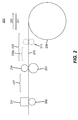
- control of the tension in approximate region 208 of the receiver can be achieved by providing a properly sized clutch (torque limiter) on the output of the drive motor for receiver roll 206 (not shown).
- the clutch control can be used to adjust tension in the receiver in approximate region 208.
- An alternative method for controlling the tension in approximate region 208 of the receiver includes adding rollers 210 which would likewise be driven by a motor with a properly sized clutch on its output. This would reduce the length of controlled tension approximate region 208 to that approximate portion indicated by the dashed line bracket 208a.
- roll 206 or rollers 210 would feed receiver 205 faster than the capstan, thus causing the clutch to slip and maintain a constant torque, during a forward feed printing phase of printer 100 and reverse feed the receiver slower than the capstan, again causing the clutch to slip and maintain a constant torque during its rewind phase. Both of these adjustments, one each for forward feed and for reverse feed, increase tension in the receiver in approximate region 208.
- the capstan 203 uses a straight knurl pattern with ridges running along the length of the roller parallel to its axis of rotation as shown in FIGs. 4A-B .
- the ridges are disposed at a frequency of 10 to 30 ridges/cm at a depth of at least 10 microns.
- the pinch roller is composed of a steel shaft covered with an elastomeric material with a shore-A durometer ranging from 20 to 60, with a 50 micron Teflon sleeve covering the elastomer.
- This preferred embodiment is a softer and thinner version of conventional elastomer roller covers.
- a softer pinch roller aids in eliminating marks in the receiver but often results in more slippage of the receiver due to lower traction.
- Controlling tension in the receiver on both sides of the capstan roller can reduce or eliminate slippage.
- the tension of the receiver between the receiver roll and the capstan, approximate region 108, produced during printing should be more than about 50% of the tension existing between the capstan and the thermal print head, approximate region 107. This percentage is higher than the unregulated tension commonly existing in thermal printers.
- the clutched motor is designed to provide a predesigned load, which controls an amount of tension applied to the receiver at approximate region 108.
- Manual trial and error clutch adjustment can be fine tuned by monitoring performance of the printer, then manually leaving the clutch set at the desired adjustment point. This procedure can be undertaken during the design phase to establish a factory setting. Depending on the design of the printer, characteristics such as thermal head drag and capstan traction might require more or less tension between the receiver roll and the capstan to achieve proper image registration.
- the receiver roll diameter ranges from about 7 inches diameter when full to about 3.5 inches when depleted for the spool diameter, which should be compensated by controlling motor speed and torque during depletion of the receiver media.
- a full roll weighs approximately 5-6 pounds. If the clutch is driving the paper roll, the RPM of the motor output must be determined based on the smallest possible roll diameter during the printing cycle and on the largest possible diameter during the rewind cycle to insure that the clutch slips and maintains tension properly. If the clutch is driving a second pair of rollers, for example, the alternate rollers 210, the roll diameter is not a concern.
- the clutch operates by attaching part of it to the shaft and another concentric part attached to a drive component such as a gear or pulley. These two parts of the clutch are coupled to each other only by friction which produces a limited amount of torque when slippage of one half relative to the other occurs. Typically, this friction coupling is adjustable for controlling an amount of mechanically transmitted torque.
- the torque can be varied in a stepwise fashion until the color to color registration is within specification.
- Some possible ways to vary the torque to determine an acceptable value are to use an adjustable clutch, a series of fixed-value clutches or a pulley and weight system attached to the paper roll. This same technique can be used whether the clutch is driving the paper roll or a second pair of rollers.
- the precision of the tension control will depend on the gripping capability of the capstan roller. The less the gripping capability, the more tension control is required.
- Other more precise methods of controlling tension include (1) the use of a three-roll cluster, the middle roller being a "dancer” roller which has a wrap angle of approximately 180° and exerts a constant force on the web (receiver); and (2) using a closed-loop system in which a tension sensor feeds back a signal to a DC motor which drives either the receiver roll 206 or the second pair of rollers 210.
- the data point at head load spring 505 value 3.2, pinch roller spring 504 value 3.8, and pinch roller 503 value 40 shore A durometer shows an in-track performance of approximately -18 thousandths of an inch.
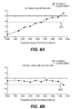
- FIGs. 8A and 8B experimental testing measured in-track and cross-track registration, respectively, with varying tension applied to the receiver in region 108, with resulting data points as shown in this figure. Testing procedures were undertaken by measurably controlling the torque applied to roll 106. Horizontal baselines 801, 802 indicate a preferred minimum in-track and cross-track performance of about -6 thousandths of an inch. As is illustrated in FIG. 8A , in-track registration with zero error is achieved using approximately 7 newtons of added tension. Cross-track registration, shown in 8B, begins to deviate below the baseline with added tension of this magnitude.
Landscapes
- Handling Of Sheets (AREA)
- Handling Of Continuous Sheets Of Paper (AREA)
- Electronic Switches (AREA)
- Controlling Rewinding, Feeding, Winding, Or Abnormalities Of Webs (AREA)
- Delivering By Means Of Belts And Rollers (AREA)
Description
- The present invention is directed to thermal printing. In particular, a printer apparatus and method is disclosed for printing on receiver media without damaging the media.
- Currently, most thermal printers achieve acceptable color to color image registration by the use of a capstan roller having sharp peaks, as shown in
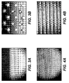
FIGs. 3A-B , which penetrate the receiver for optimum traction to avoid slippage during receiver transport. While this presents no grave problems for a simplex print, since the marks produced are on the back side of the print, for duplex printing this unimproved method leaves noticeable impression marks on thermal receiver media constructed with a dual-sided voided layer. The impression marks appear in the image area of the print. These impression marks, or depressions, do not allow dye from the dye donor web to reach the receiver media which leaves behind discolored areas on the print, such as white dots. It is noted that the present invention is not limited in any way only to duplex printing methods because the non perforating design of the presently disclosed methods and apparatuses can be implemented in non-duplex printing systems. - A thermal printer including a system of rollers for moving a receiving sheet through the printer is disclosed in
US 2008 122 917 A , which discloses a thermal printer that pinches an ink ribbon in contact with a receiver sheet in between a thermal head and a platen roller. Here, the driving mechanism for advancing a receiving sheet in the printing path is attached to the platen roller. According to this design, a tension is always applied in the receiver paper between a capstan roller and a platen roller. - In accordance with the present invention, a thermal printer as set forth in claim 1 and a drive system as set forth in claim 11 are provided. Preferred embodiments of the present invention incorporate the use of a less aggressive capstan roller design along with a softer pinch roller to eliminate impression marks in the thermal receiver. To compensate for the less aggressive grip on the receiver, a tension differential across the capstan is controllably decreased. By increasing tension in the receiver on the roll side of the capstan during printing, an acceptable color to color image registration is produced. The capstan uses a straight (longitudinal) knurl pattern with ridges running along the length of the roller parallel to its axis of rotation, as shown in
FIGs. 4A-B . The ridges are disposed at a frequency of 10 to 30 ridges per inch. The depth of these ridges being at least 10 microns. Other methods of achieving high traction, non-marking surfaces include the use of plasma coatings, thin elastomeric coatings, and increasing the wrap angle of the receiver around the capstan. In the case of a duplex printer, this invention is applicable whether the printer incorporates a single web path with print heads on both sides of the receiver or separate web paths for individually imaging each side of the sheet. - The pinch roller of a preferred embodiment of the present inventions is composed of a steel shaft covered with an elastomeric material having a shore-A durometer ranging from 20 to 60, with a 50 micron Teflon sleeve covering the elastomer. The tension of the receiver between the receiver roll and the capstan,
region 108, produced during a printing phase should be maintained at more than 50% of the tension existing between the capstan and the thermal print head,region 107. This amounts to less than 50% tension differential across the capstan roller. These preferred embodiments of the invention do not require slowing down the print speed. - A preferred embodiment of the present invention includes a printer comprising a thermal print head for applying thermal media onto a receiver, a capstan roller disposed between the thermal print head and a supply of receiver media for controlling a feed of the receiver to the print head, and means for maintaining a minimum tension of the receiver between the supply of receiver and the capstan roller. The capstan roller is uniquely knurled with a longitudinal knurl pattern having a depth of at least about 10 microns and does not contain sharp points that may penetrate the receiver. Rather, it comprises a high traction, non-marking surface. A pinch roller adjacent the capstan roller forms a nip for the receiver. The pinch roller comprises an elastomeric material thereon having a shore-A durometer ranging from about 20 to about 60, preferably closer to about 40. The means for maintaining tension comprises a motor and a torque limiter that drives the roll holding the supply of receiver. Alternately, the motor and torque limiter can be applied to a second pair of rollers between the supply of receiver and the capstan roller. In either embodiment, the receiver is maintained in a taut state in a region of the receiver adjacent the capstan roller. This controlled tension helps to maintain a printing registration within a preselected tolerance.
- Another preferred embodiment of the present invention comprises a drive system with a first pair of rollers forming a nip for feeding a receiver medium toward a print head. A receiver supply roll has a supply of the receiver wound thereon and supplies the receiver to the first pair of rollers. A means for maintaining a minimum tension acts upon the receiver in a region between the receiver supply roll and the first pair of rollers. The means may include a control means for controllably rotating the receiver supply roll for maintaining the minimum tension, or it can include a second pair of rollers between the receiver supply roll and the first pair of rollers. The second pair of rollers can control a tension of the receiver between the second pair of rollers and the first pair of rollers in response to a movement of the receiver through the first pair of rollers.
- Another preferred embodiment of the present invention comprises a printer including a supply roll of receiver media for printing thereon. A plurality of rollers in the printer feed the receiver media through the printer. A means for maintaining a preselected tension of the receiver media between the supply roll and a pair of the plurality of rollers can include a motor with a torque limiter. The motor can be attached to the supply roll for driving the supply roll. Alternately, it can be attached to an optional pair of rollers adjacent the supply roll. The pair of the plurality of rollers (not referring to the optional pair) comprises a capstan roller having a high traction, non-marking surface, which can comprise a longitudinal knurl pattern.
- These, and other, aspects and objects of the present invention will be better appreciated and understood when considered in conjunction with the following description and the accompanying drawings. It should be understood, however, that the following description, while indicating preferred embodiments of the present invention and numerous specific details thereof, is given by way of illustration and not of limitation. For example, the summary descriptions above are not meant to describe individual separate embodiments whose elements are not interchangeable. In fact, many of the elements described as related to a particular embodiment can be used together with, and possibly interchanged with, elements of other described embodiments. Many changes and modifications may be made within the scope of the present invention without departing from the spirit thereof, and the invention includes all such modifications. It is also noted that other approaches to this problem could include eliminating the capstan and letting the platen roller be the main drive roller or in the case of a duplex printer, filling in or coating over the holes left by the capstan before printing over them, The figures below are intended to be drawn neither to any precise scale with respect to relative size, angular relationship, or relative position nor to any combinational relationship with respect to interchangeability, substitution, or representation of an actual implementation.
-
-
FIG. 1 illustrates a receiver feed mechanism. -
FIG. 2 illustrates a receiver feed mechanism with tension control rollers. -
FIGs. 3A-B illustrate views of a sharp point capstan roller. -
FIGs. 4A-B illustrate views of a longitudinal knurled roller. -
FIG. 5 illustrates in-track data points using different modifications. -
FIG. 6 illustrates cross-track data points using different modifications. -
FIG. 7 illustrates impression mark data points using different modifications. -
FIGs. 8A-B illustrate in-track and cross-track registration performance using different receiver tensions. - With reference to
FIG. 1 there is illustrated a portion of a thermal printer's drive system. Aroll 106 ofreceiver 105 is fed through athermal printer 100 as shown by the receiver advancing pastthermal print head 101, as fed bythermal roller 102,pinch roller 104 andcapstan roller 103. Dye donor web 109 (partially illustrated) is applied onto the receiver in predetermined patterns, as is well known in the art. The receiver is iteratively reversed and printed during several color applications of the dye donor web in the predetermined patterns. Tension inapproximate region 107 relative toapproximate region 108 affect an ability of the capstan and pinch rollers to effectively control movement of the receiver therethrough. - A preferred embodiment of the present invention comprises a less
aggressive capstan roller 103 design, as is illustrated inFIGs. 4A-B wherein a knurled pattern provides a spike free configuration that does not perforate a surface ofreceiver 105 as would the spiked configuration of the capstan roller shown inFIG. 3A-B . Together with asofter pinch roller 104, impression marks are not formed in the thermal receiver as it passes between capstan andpinch rollers approximate regions capstan 108 during printing, an acceptable color to color image registration is produced. This increase in the tension inapproximate area 108 reduces the tension differential acrosscapstan roller 103. - Referring to
FIG.2 , control of the tension inapproximate region 208 of the receiver can be achieved by providing a properly sized clutch (torque limiter) on the output of the drive motor for receiver roll 206 (not shown). The clutch control can be used to adjust tension in the receiver inapproximate region 208. An alternative method for controlling the tension inapproximate region 208 of the receiver includes addingrollers 210 which would likewise be driven by a motor with a properly sized clutch on its output. This would reduce the length of controlled tensionapproximate region 208 to that approximate portion indicated by the dashedline bracket 208a. In a preferred embodiment, roll 206 orrollers 210 would feedreceiver 205 faster than the capstan, thus causing the clutch to slip and maintain a constant torque, during a forward feed printing phase ofprinter 100 and reverse feed the receiver slower than the capstan, again causing the clutch to slip and maintain a constant torque during its rewind phase. Both of these adjustments, one each for forward feed and for reverse feed, increase tension in the receiver inapproximate region 208. - The
capstan 203 uses a straight knurl pattern with ridges running along the length of the roller parallel to its axis of rotation as shown inFIGs. 4A-B . The ridges are disposed at a frequency of 10 to 30 ridges/cm at a depth of at least 10 microns. - The pinch roller is composed of a steel shaft covered with an elastomeric material with a shore-A durometer ranging from 20 to 60, with a 50 micron Teflon sleeve covering the elastomer. This preferred embodiment is a softer and thinner version of conventional elastomer roller covers. A softer pinch roller aids in eliminating marks in the receiver but often results in more slippage of the receiver due to lower traction. Controlling tension in the receiver on both sides of the capstan roller can reduce or eliminate slippage. The tension of the receiver between the receiver roll and the capstan,
approximate region 108, produced during printing should be more than about 50% of the tension existing between the capstan and the thermal print head,approximate region 107. This percentage is higher than the unregulated tension commonly existing in thermal printers. - The clutched motor, either used for
roll 206 or forrollers 210, or both, is designed to provide a predesigned load, which controls an amount of tension applied to the receiver atapproximate region 108. Manual trial and error clutch adjustment can be fine tuned by monitoring performance of the printer, then manually leaving the clutch set at the desired adjustment point. This procedure can be undertaken during the design phase to establish a factory setting. Depending on the design of the printer, characteristics such as thermal head drag and capstan traction might require more or less tension between the receiver roll and the capstan to achieve proper image registration. The receiver roll diameter ranges from about 7 inches diameter when full to about 3.5 inches when depleted for the spool diameter, which should be compensated by controlling motor speed and torque during depletion of the receiver media. In an eight inch printer width, a full roll weighs approximately 5-6 pounds. If the clutch is driving the paper roll, the RPM of the motor output must be determined based on the smallest possible roll diameter during the printing cycle and on the largest possible diameter during the rewind cycle to insure that the clutch slips and maintains tension properly. If the clutch is driving a second pair of rollers, for example, thealternate rollers 210, the roll diameter is not a concern. - The clutch operates by attaching part of it to the shaft and another concentric part attached to a drive component such as a gear or pulley. These two parts of the clutch are coupled to each other only by friction which produces a limited amount of torque when slippage of one half relative to the other occurs. Typically, this friction coupling is adjustable for controlling an amount of mechanically transmitted torque.
- To determine a value of the torque that the clutch must transmit to the receiver to achieve accurate registration, the torque can be varied in a stepwise fashion until the color to color registration is within specification. Some possible ways to vary the torque to determine an acceptable value are to use an adjustable clutch, a series of fixed-value clutches or a pulley and weight system attached to the paper roll. This same technique can be used whether the clutch is driving the paper roll or a second pair of rollers. The precision of the tension control will depend on the gripping capability of the capstan roller. The less the gripping capability, the more tension control is required.
- Other more precise methods of controlling tension include (1) the use of a three-roll cluster, the middle roller being a "dancer" roller which has a wrap angle of approximately 180° and exerts a constant force on the web (receiver); and (2) using a closed-loop system in which a tension sensor feeds back a signal to a DC motor which drives either the
receiver roll 206 or the second pair ofrollers 210. - With reference to
FIG. 5 , experimental testing measured in-track registration, i.e. same direction as receiver movement through the printer, with resulting data points as shown in this figure. Testing procedures used straightknurl capstan roller 502, as described above, varying pinchroller hardness modifications 503, different pinch roller pressure modifications as applied with pinch roller springs 504, and different print headload pressure modifications 505, also applied via springs. There is a data point for each of these different print headload pressure modifications 505 shown in the graph, which tests were repeated using the different pinch roller modifications and pinch roller pressure modifications as shown.Horizontal baseline 501 line indicates a preferred minimum in-track performance of about -6 thousandths of an inch. To illustrate the scale of the graph shown relative to this -6 performance, the data point athead load spring 505 value 3.2,pinch roller spring 504 value 3.8, andpinch roller 503 value 40 shore A durometer, shows an in-track performance of approximately -18 thousandths of an inch. - With reference to
FIG. 6 , experimental testing measured cross-track registration, i.e. perpendicular to in-track registration, with resulting data points as shown in this figure. Testing procedures used straightknurl capstan roller 602, as described above, varying pinchroller hardness modifications 603, different pinch roller pressure modifications as applied with pinch roller springs 604, and different print headload pressure modifications 605, also applied via springs. There is a data point for each of these different print headload pressure modifications 605 shown in the graph, most of which tests were repeated using the different pinch roller modifications and pinch roller pressure modifications as shown.Horizontal baselines inch 601 and -6 thousandths of aninch 606, with zero cross-track error indicated bydotted line 607. The two performances closest to zero cross-track error indicated in this figure was achieved with pinch roller hardness of 40 shore A durometer, pinch roller spring tension (measured in kgf) of 4.9, and head load spring magnitude (also measured in kgf) 2.8 and 3.2. - With reference to
FIG. 7 , experimental testing measured impression marks in the receiver caused by thecapstan 702, with resulting data points as shown in this figure. Testing procedures used straightknurl capstan roller 702, as described above, varying pinchroller hardness modifications 703, different pinch roller pressure modifications as applied with pinch roller springs 704, and different print headload pressure modifications 705, also applied via springs. There is a data point for each of these different print headload pressure modifications 705 shown in the graph, most of which tests were repeated using the different pinch roller modifications and pinch roller pressure modifications as shown.Horizontal baselines 701 indicate resulting performance. The lowest line indicates that the impression is invisible to the naked eye and requires a loop to be seen; the second lowest horizontal line indicates an impression mark that can be seen by the naked eye but is not obvious. The remaining three horizontal lines indicate, in an upward progression, increasingly noticeable impression marks. Performance having less noticeable impression marks is preferred. - With reference to
FIGs. 8A and 8B , experimental testing measured in-track and cross-track registration, respectively, with varying tension applied to the receiver inregion 108, with resulting data points as shown in this figure. Testing procedures were undertaken by measurably controlling the torque applied to roll 106.Horizontal baselines FIG. 8A , in-track registration with zero error is achieved using approximately 7 newtons of added tension. Cross-track registration, shown in 8B, begins to deviate below the baseline with added tension of this magnitude. -
- 100
- Printing System
- 101
- Print Head
- 102
- Roller
- 103
- Roller
- 104
- Roller
- 105
- Receiver
- 106
- Supply Roll
- 107
- Receiver region
- 108
- Receiver region\
- 109
- Donor
- 200
- Printing System
- 201
- Print Head
- 202
- Roller
- 203
- Roller
- 204
- Roller
- 205
- Receiver
- 206
- Supply Roll
- 207
- Receiver region
- 208
- Receiver region
- 208a
- Receiver region
- 210
- Rollers
- 220
- Direction
- 221
- Direction
- 501
- Horizontal line
- 502
- Field
- 503
- Field
- 504
- Field
- 505
- Field
- 601
- Upper axis
- 602
- Field
- 603
- Field
- 604
- Field
- 605
- Field
- 606
- Lower axis
- 607
- Zero axis
- 701
- Horizontal axes
- 702
- Field
- 703
- Field
- 704
- Field
- 705
- Field
- 801
- Lower axis
- 802
- Lower axis
Claims (13)
- A thermal printer (100; 200) comprising:a thermal print head (101; 201) for applying thermal media (109) onto a receiver (105; 205);a capstan roller (103; 203; 502; 602; 702) disposed between the thermal print head (101; 201) and a supply (106; 206) of the receiver (105; 205) for controlling a feed of the receiver (105; 205) to the print head (101; 201); anda motor and a torque limiter for maintaining a minimum tension of the receiver (105; 205) between the supply (106; 206) of receiver (105; 205) and the capstan roller (103; 203; 502; 602; 702).
- The thermal printer (100; 200) of claim 1, wherein the capstan roller (103; 203; 502; 602; 702) comprises a longitudinal knurl pattern.
- The thermal printer (100; 200) of claim 1, wherein the capstan roller (103; 203; 502; 602; 702) comprises a high traction, non-marking surface.
- The thermal printer (100; 200) of claim 3, further comprising a pinch roller (104; 204; 503; 603; 703) adjacent the capstan roller (103; 203; 502; 602; 702) for forming a nip therebetween for the receiver (105; 205), the pinch roller (104; 204; 503; 603; 703) comprising an elastomeric material thereon having a shore-A durometer ranging from about 20 to about 60.
- The thermal printer (100; 200) of claim 3, further comprising a pinch roller (104; 204; 503; 603; 703) adjacent the capstan roller (103; 203; 502; 602; 702) for forming a nip therebetween for the receiver (105; 205), the pinch roller (104; 204; 503; 603; 703) comprising an elastomeric material thereon having a shore-A durometer of about 40.
- The thermal printer (100; 200) of claim 3, wherein a depth of the longitudinal knurl pattern is at least about 10 microns.
- The thermal printer (100; 200) of claim 1, wherein the motor controllably rotates the supply (106; 206) of receiver (105; 205).
- The thermal printer (100; 200) of claim 1, wherein the motor controls a pair of rollers (210) between the supply (106; 206) of the receiver (105; 205) and the capstan roller (103; 203; 502; 602; 702).
- The thermal printer (100; 200) of claim 1, wherein the motor and torque limiter maintains the receiver (105; 205) in a taut state in a region of the receiver adjacent the capstan roller (103; 203; 502; 602; 702).
- The thermal printer (100; 200) of claim 1, wherein the motor and torque limiter maintains a printing registration within a preselected tolerance.
- A drive system comprising:a first pair of rollers (103, 104; 203, 204; 502, 503; 602, 603; 702, 703) forming a nip and having a receiver (105; 205) traveling therethrough toward a print head (101; 201);a receiver supply roll (106; 206) having a supply of the receiver (105; 205) wound thereon for supplying the receiver (105; 205) to the first pair of rollers (103, 104; 203, 204; 502, 503; 602, 603; 702, 703); anda motor and a torque limiter for maintaining a minimum tension of a region (108; 208) of the receiver between the receiver supply roll (106; 206) and the first pair of rollers (103, 104; 203, 204; 502, 503; 602, 603; 702, 703).
- The system of claim 11, wherein the motor and torque limiter includes a control means for controllably rotating the receiver supply roll (106; 206) for maintaining the minimum tension of the region (108; 208) of the receiver (105; 205) between the receiver supply roll (106; 206) and the first pair of rollers (103, 104; 203, 204; 502, 503; 602, 603; 702, 703).
- The drive system of claim 11, wherein the motor and torque limiter comprises a second pair of rollers (210) between the receiver supply roll (106; 206) and the first pair of rollers (103, 104; 203, 204; 502, 503; 602, 603; 702, 703), the second pair of rollers (210) having the receiver (105; 205) traveling therebetween from the receiver supply roll (106; 206) toward the first pair of rollers (103, 104; 203, 204; 502, 503; 602, 603; 702, 703), the second pair of rollers (210) for controlling a tension of the receiver (105; 205) between the second pair of rollers (210) and the first pair of rollers (103, 104; 203, 204; 502, 503; 602, 603; 702, 703) in response to a movement of the receiver (105; 205) through the first pair of rollers (103, 104; 203, 204; 502, 503; 602, 603; 702, 703).
Applications Claiming Priority (2)
| Application Number | Priority Date | Filing Date | Title |
|---|---|---|---|
| US13/032,897 US8810620B2 (en) | 2011-02-23 | 2011-02-23 | Thermal printer |
| PCT/US2012/025784 WO2012115893A1 (en) | 2011-02-23 | 2012-02-20 | Thermal printer |
Publications (2)
| Publication Number | Publication Date |
|---|---|
| EP2678163A1 EP2678163A1 (en) | 2014-01-01 |
| EP2678163B1 true EP2678163B1 (en) | 2016-07-27 |
Family
ID=45787358
Family Applications (1)
| Application Number | Title | Priority Date | Filing Date |
|---|---|---|---|
| EP12706988.8A Active EP2678163B1 (en) | 2011-02-23 | 2012-02-20 | Thermal printer |
Country Status (7)
| Country | Link |
|---|---|
| US (1) | US8810620B2 (en) |
| EP (1) | EP2678163B1 (en) |
| JP (1) | JP6030074B2 (en) |
| CN (1) | CN103429434B (en) |
| BR (1) | BR112013018698A8 (en) |
| TW (1) | TWI566956B (en) |
| WO (1) | WO2012115893A1 (en) |
Families Citing this family (2)
| Publication number | Priority date | Publication date | Assignee | Title |
|---|---|---|---|---|
| EP3429855B1 (en) | 2016-07-28 | 2022-06-29 | Hewlett-Packard Development Company, L.P. | Wiper roll to cause friction on a print medium |
| US10552708B2 (en) | 2018-03-07 | 2020-02-04 | Xerox Corporation | Method and system for extracting impression marks using a mobile application |
Family Cites Families (16)
| Publication number | Priority date | Publication date | Assignee | Title |
|---|---|---|---|---|
| US4720714A (en) * | 1983-03-31 | 1988-01-19 | Nec Yonezawa, Ltd. | Plotter comprising a rotatable platen displaced from a sheet feeder |
| JPS6297872A (en) * | 1985-10-24 | 1987-05-07 | Seiko Epson Corp | paper feed mechanism |
| JPH0274371A (en) * | 1988-09-12 | 1990-03-14 | Matsushita Electric Ind Co Ltd | Color recorder |
| JPH02158539A (en) * | 1988-12-12 | 1990-06-19 | Canon Inc | Sheet conveyance device |
| JPH0313449A (en) * | 1989-06-12 | 1991-01-22 | Kato Hatsujo Kaisha Ltd | Manufacture of high friction roller |
| US5264873A (en) | 1992-09-04 | 1993-11-23 | Eastman Kodak Company | Traction surfaces for thermal printer capstan drives |
| JP2000015886A (en) * | 1998-06-30 | 2000-01-18 | Shinko Electric Co Ltd | Color printer |
| JP2000033720A (en) * | 1998-07-17 | 2000-02-02 | Matsushita Electric Ind Co Ltd | Thermal transfer printer |
| JP3454227B2 (en) * | 2000-05-12 | 2003-10-06 | 日本電気株式会社 | Roll paper slack prevention mechanism |
| JP2002331714A (en) * | 2001-03-09 | 2002-11-19 | Fuji Photo Film Co Ltd | Color thermal printer |
| JP3840118B2 (en) * | 2002-02-05 | 2006-11-01 | 富士写真フイルム株式会社 | Color thermal printer |
| US7777773B2 (en) * | 2004-01-28 | 2010-08-17 | Eastman Kodak Company | Image quality attributes tracking and preventive maintenance prediction |
| JP2007196454A (en) * | 2006-01-24 | 2007-08-09 | Sony Corp | Thermal printer and thermal printer printing method |
| JP4939147B2 (en) * | 2006-08-28 | 2012-05-23 | キヤノン株式会社 | Recording device |
| JP5332409B2 (en) * | 2008-08-29 | 2013-11-06 | セイコーエプソン株式会社 | Printing method and printing apparatus |
| JP2010247914A (en) | 2009-04-13 | 2010-11-04 | Sony Corp | Image recording medium conveying apparatus and image forming apparatus |
-
2011
- 2011-02-23 US US13/032,897 patent/US8810620B2/en active Active
-
2012
- 2012-02-20 JP JP2013555468A patent/JP6030074B2/en active Active
- 2012-02-20 WO PCT/US2012/025784 patent/WO2012115893A1/en not_active Ceased
- 2012-02-20 EP EP12706988.8A patent/EP2678163B1/en active Active
- 2012-02-20 CN CN201280007483.7A patent/CN103429434B/en not_active Expired - Fee Related
- 2012-02-20 BR BR112013018698A patent/BR112013018698A8/en not_active Application Discontinuation
- 2012-02-22 TW TW101105909A patent/TWI566956B/en not_active IP Right Cessation
Also Published As
| Publication number | Publication date |
|---|---|
| JP2014511145A (en) | 2014-05-12 |
| WO2012115893A1 (en) | 2012-08-30 |
| TW201238783A (en) | 2012-10-01 |
| BR112013018698A2 (en) | 2016-10-18 |
| CN103429434A (en) | 2013-12-04 |
| CN103429434B (en) | 2016-07-06 |
| US8810620B2 (en) | 2014-08-19 |
| BR112013018698A8 (en) | 2018-02-06 |
| JP6030074B2 (en) | 2016-11-24 |
| US20120212560A1 (en) | 2012-08-23 |
| TWI566956B (en) | 2017-01-21 |
| EP2678163A1 (en) | 2014-01-01 |
Similar Documents
| Publication | Publication Date | Title |
|---|---|---|
| US5820280A (en) | Printer with variable torque distribution | |
| EP1980399B1 (en) | Mechanism for transfix member with idle movement | |
| JP5406808B2 (en) | Continuous web conveying system used in continuous web image forming apparatus | |
| EP3328651B1 (en) | Printing apparatus | |
| US8810620B2 (en) | Thermal printer | |
| US8922612B2 (en) | Thermal printing | |
| JP2000238353A (en) | Medium transfer system | |
| JP2000015886A (en) | Color printer | |
| JP2012213896A (en) | Printer | |
| HK1191615B (en) | Thermal printer | |
| HK1191615A (en) | Thermal printer | |
| US20120268545A1 (en) | Ribbon capable of enhancing cutting precision | |
| EP1731317A1 (en) | Thermal transfer printer for film | |
| JPH0439237A (en) | Sheet conveying device | |
| JP2011046157A (en) | Thermal printer | |
| CN101856918B (en) | Image recording medium transfer apparatus and image formation apparatus | |
| JP4359064B2 (en) | Ribbon winder for thermal transfer printer | |
| JP4697440B2 (en) | Recording device, liquid ejecting device | |
| JP2014511145A5 (en) | ||
| EP3636568B1 (en) | Sheet transport apparatus for an inkjet sheet printer | |
| JP7228127B2 (en) | Printer device and its control method | |
| JP2813180B2 (en) | Paper scanning mechanism of image forming apparatus | |
| US20050117011A1 (en) | Image-recording device | |
| JPH11293558A (en) | Ink jet printer | |
| JP2018070311A (en) | Printing apparatus |
Legal Events
| Date | Code | Title | Description |
|---|---|---|---|
| PUAI | Public reference made under article 153(3) epc to a published international application that has entered the european phase |
Free format text: ORIGINAL CODE: 0009012 |
|
| 17P | Request for examination filed |
Effective date: 20130701 |
|
| AK | Designated contracting states |
Kind code of ref document: A1 Designated state(s): AL AT BE BG CH CY CZ DE DK EE ES FI FR GB GR HR HU IE IS IT LI LT LU LV MC MK MT NL NO PL PT RO RS SE SI SK SM TR |
|
| DAX | Request for extension of the european patent (deleted) | ||
| 17Q | First examination report despatched |
Effective date: 20150205 |
|
| GRAP | Despatch of communication of intention to grant a patent |
Free format text: ORIGINAL CODE: EPIDOSNIGR1 |
|
| INTG | Intention to grant announced |
Effective date: 20160209 |
|
| GRAS | Grant fee paid |
Free format text: ORIGINAL CODE: EPIDOSNIGR3 |
|
| GRAA | (expected) grant |
Free format text: ORIGINAL CODE: 0009210 |
|
| AK | Designated contracting states |
Kind code of ref document: B1 Designated state(s): AL AT BE BG CH CY CZ DE DK EE ES FI FR GB GR HR HU IE IS IT LI LT LU LV MC MK MT NL NO PL PT RO RS SE SI SK SM TR |
|
| REG | Reference to a national code |
Ref country code: GB Ref legal event code: FG4D |
|
| REG | Reference to a national code |
Ref country code: CH Ref legal event code: EP |
|
| REG | Reference to a national code |
Ref country code: AT Ref legal event code: REF Ref document number: 815466 Country of ref document: AT Kind code of ref document: T Effective date: 20160815 |
|
| REG | Reference to a national code |
Ref country code: IE Ref legal event code: FG4D |
|
| REG | Reference to a national code |
Ref country code: DE Ref legal event code: R096 Ref document number: 602012020972 Country of ref document: DE |
|
| REG | Reference to a national code |
Ref country code: NL Ref legal event code: FP |
|
| REG | Reference to a national code |
Ref country code: LT Ref legal event code: MG4D |
|
| REG | Reference to a national code |
Ref country code: AT Ref legal event code: MK05 Ref document number: 815466 Country of ref document: AT Kind code of ref document: T Effective date: 20160727 |
|
| REG | Reference to a national code |
Ref country code: FR Ref legal event code: PLFP Year of fee payment: 6 |
|
| PG25 | Lapsed in a contracting state [announced via postgrant information from national office to epo] |
Ref country code: IT Free format text: LAPSE BECAUSE OF FAILURE TO SUBMIT A TRANSLATION OF THE DESCRIPTION OR TO PAY THE FEE WITHIN THE PRESCRIBED TIME-LIMIT Effective date: 20160727 Ref country code: IS Free format text: LAPSE BECAUSE OF FAILURE TO SUBMIT A TRANSLATION OF THE DESCRIPTION OR TO PAY THE FEE WITHIN THE PRESCRIBED TIME-LIMIT Effective date: 20161127 Ref country code: FI Free format text: LAPSE BECAUSE OF FAILURE TO SUBMIT A TRANSLATION OF THE DESCRIPTION OR TO PAY THE FEE WITHIN THE PRESCRIBED TIME-LIMIT Effective date: 20160727 Ref country code: HR Free format text: LAPSE BECAUSE OF FAILURE TO SUBMIT A TRANSLATION OF THE DESCRIPTION OR TO PAY THE FEE WITHIN THE PRESCRIBED TIME-LIMIT Effective date: 20160727 Ref country code: NO Free format text: LAPSE BECAUSE OF FAILURE TO SUBMIT A TRANSLATION OF THE DESCRIPTION OR TO PAY THE FEE WITHIN THE PRESCRIBED TIME-LIMIT Effective date: 20161027 Ref country code: RS Free format text: LAPSE BECAUSE OF FAILURE TO SUBMIT A TRANSLATION OF THE DESCRIPTION OR TO PAY THE FEE WITHIN THE PRESCRIBED TIME-LIMIT Effective date: 20160727 Ref country code: LT Free format text: LAPSE BECAUSE OF FAILURE TO SUBMIT A TRANSLATION OF THE DESCRIPTION OR TO PAY THE FEE WITHIN THE PRESCRIBED TIME-LIMIT Effective date: 20160727 |
|
| PG25 | Lapsed in a contracting state [announced via postgrant information from national office to epo] |
Ref country code: PT Free format text: LAPSE BECAUSE OF FAILURE TO SUBMIT A TRANSLATION OF THE DESCRIPTION OR TO PAY THE FEE WITHIN THE PRESCRIBED TIME-LIMIT Effective date: 20161128 Ref country code: LV Free format text: LAPSE BECAUSE OF FAILURE TO SUBMIT A TRANSLATION OF THE DESCRIPTION OR TO PAY THE FEE WITHIN THE PRESCRIBED TIME-LIMIT Effective date: 20160727 Ref country code: SE Free format text: LAPSE BECAUSE OF FAILURE TO SUBMIT A TRANSLATION OF THE DESCRIPTION OR TO PAY THE FEE WITHIN THE PRESCRIBED TIME-LIMIT Effective date: 20160727 Ref country code: AT Free format text: LAPSE BECAUSE OF FAILURE TO SUBMIT A TRANSLATION OF THE DESCRIPTION OR TO PAY THE FEE WITHIN THE PRESCRIBED TIME-LIMIT Effective date: 20160727 Ref country code: PL Free format text: LAPSE BECAUSE OF FAILURE TO SUBMIT A TRANSLATION OF THE DESCRIPTION OR TO PAY THE FEE WITHIN THE PRESCRIBED TIME-LIMIT Effective date: 20160727 Ref country code: BE Free format text: LAPSE BECAUSE OF FAILURE TO SUBMIT A TRANSLATION OF THE DESCRIPTION OR TO PAY THE FEE WITHIN THE PRESCRIBED TIME-LIMIT Effective date: 20160727 Ref country code: GR Free format text: LAPSE BECAUSE OF FAILURE TO SUBMIT A TRANSLATION OF THE DESCRIPTION OR TO PAY THE FEE WITHIN THE PRESCRIBED TIME-LIMIT Effective date: 20161028 Ref country code: ES Free format text: LAPSE BECAUSE OF FAILURE TO SUBMIT A TRANSLATION OF THE DESCRIPTION OR TO PAY THE FEE WITHIN THE PRESCRIBED TIME-LIMIT Effective date: 20160727 |
|
| PG25 | Lapsed in a contracting state [announced via postgrant information from national office to epo] |
Ref country code: RO Free format text: LAPSE BECAUSE OF FAILURE TO SUBMIT A TRANSLATION OF THE DESCRIPTION OR TO PAY THE FEE WITHIN THE PRESCRIBED TIME-LIMIT Effective date: 20160727 Ref country code: EE Free format text: LAPSE BECAUSE OF FAILURE TO SUBMIT A TRANSLATION OF THE DESCRIPTION OR TO PAY THE FEE WITHIN THE PRESCRIBED TIME-LIMIT Effective date: 20160727 |
|
| REG | Reference to a national code |
Ref country code: DE Ref legal event code: R097 Ref document number: 602012020972 Country of ref document: DE |
|
| PG25 | Lapsed in a contracting state [announced via postgrant information from national office to epo] |
Ref country code: SK Free format text: LAPSE BECAUSE OF FAILURE TO SUBMIT A TRANSLATION OF THE DESCRIPTION OR TO PAY THE FEE WITHIN THE PRESCRIBED TIME-LIMIT Effective date: 20160727 Ref country code: SM Free format text: LAPSE BECAUSE OF FAILURE TO SUBMIT A TRANSLATION OF THE DESCRIPTION OR TO PAY THE FEE WITHIN THE PRESCRIBED TIME-LIMIT Effective date: 20160727 Ref country code: BG Free format text: LAPSE BECAUSE OF FAILURE TO SUBMIT A TRANSLATION OF THE DESCRIPTION OR TO PAY THE FEE WITHIN THE PRESCRIBED TIME-LIMIT Effective date: 20161027 Ref country code: DK Free format text: LAPSE BECAUSE OF FAILURE TO SUBMIT A TRANSLATION OF THE DESCRIPTION OR TO PAY THE FEE WITHIN THE PRESCRIBED TIME-LIMIT Effective date: 20160727 Ref country code: CZ Free format text: LAPSE BECAUSE OF FAILURE TO SUBMIT A TRANSLATION OF THE DESCRIPTION OR TO PAY THE FEE WITHIN THE PRESCRIBED TIME-LIMIT Effective date: 20160727 |
|
| PLBE | No opposition filed within time limit |
Free format text: ORIGINAL CODE: 0009261 |
|
| STAA | Information on the status of an ep patent application or granted ep patent |
Free format text: STATUS: NO OPPOSITION FILED WITHIN TIME LIMIT |
|
| 26N | No opposition filed |
Effective date: 20170502 |
|
| PG25 | Lapsed in a contracting state [announced via postgrant information from national office to epo] |
Ref country code: SI Free format text: LAPSE BECAUSE OF FAILURE TO SUBMIT A TRANSLATION OF THE DESCRIPTION OR TO PAY THE FEE WITHIN THE PRESCRIBED TIME-LIMIT Effective date: 20160727 |
|
| PG25 | Lapsed in a contracting state [announced via postgrant information from national office to epo] |
Ref country code: MC Free format text: LAPSE BECAUSE OF FAILURE TO SUBMIT A TRANSLATION OF THE DESCRIPTION OR TO PAY THE FEE WITHIN THE PRESCRIBED TIME-LIMIT Effective date: 20160727 |
|
| REG | Reference to a national code |
Ref country code: CH Ref legal event code: PL |
|
| PG25 | Lapsed in a contracting state [announced via postgrant information from national office to epo] |
Ref country code: LI Free format text: LAPSE BECAUSE OF NON-PAYMENT OF DUE FEES Effective date: 20170228 Ref country code: CH Free format text: LAPSE BECAUSE OF NON-PAYMENT OF DUE FEES Effective date: 20170228 |
|
| REG | Reference to a national code |
Ref country code: IE Ref legal event code: MM4A |
|
| PG25 | Lapsed in a contracting state [announced via postgrant information from national office to epo] |
Ref country code: LU Free format text: LAPSE BECAUSE OF NON-PAYMENT OF DUE FEES Effective date: 20170220 |
|
| REG | Reference to a national code |
Ref country code: FR Ref legal event code: PLFP Year of fee payment: 7 |
|
| PG25 | Lapsed in a contracting state [announced via postgrant information from national office to epo] |
Ref country code: IE Free format text: LAPSE BECAUSE OF NON-PAYMENT OF DUE FEES Effective date: 20170220 |
|
| PG25 | Lapsed in a contracting state [announced via postgrant information from national office to epo] |
Ref country code: MT Free format text: LAPSE BECAUSE OF NON-PAYMENT OF DUE FEES Effective date: 20170220 |
|
| PG25 | Lapsed in a contracting state [announced via postgrant information from national office to epo] |
Ref country code: AL Free format text: LAPSE BECAUSE OF FAILURE TO SUBMIT A TRANSLATION OF THE DESCRIPTION OR TO PAY THE FEE WITHIN THE PRESCRIBED TIME-LIMIT Effective date: 20160727 |
|
| PG25 | Lapsed in a contracting state [announced via postgrant information from national office to epo] |
Ref country code: HU Free format text: LAPSE BECAUSE OF FAILURE TO SUBMIT A TRANSLATION OF THE DESCRIPTION OR TO PAY THE FEE WITHIN THE PRESCRIBED TIME-LIMIT; INVALID AB INITIO Effective date: 20120220 |
|
| PG25 | Lapsed in a contracting state [announced via postgrant information from national office to epo] |
Ref country code: CY Free format text: LAPSE BECAUSE OF NON-PAYMENT OF DUE FEES Effective date: 20160727 |
|
| PG25 | Lapsed in a contracting state [announced via postgrant information from national office to epo] |
Ref country code: MK Free format text: LAPSE BECAUSE OF FAILURE TO SUBMIT A TRANSLATION OF THE DESCRIPTION OR TO PAY THE FEE WITHIN THE PRESCRIBED TIME-LIMIT Effective date: 20160727 |
|
| PG25 | Lapsed in a contracting state [announced via postgrant information from national office to epo] |
Ref country code: TR Free format text: LAPSE BECAUSE OF FAILURE TO SUBMIT A TRANSLATION OF THE DESCRIPTION OR TO PAY THE FEE WITHIN THE PRESCRIBED TIME-LIMIT Effective date: 20160727 |
|
| PGFP | Annual fee paid to national office [announced via postgrant information from national office to epo] |
Ref country code: FR Payment date: 20200124 Year of fee payment: 9 |
|
| PG25 | Lapsed in a contracting state [announced via postgrant information from national office to epo] |
Ref country code: FR Free format text: LAPSE BECAUSE OF NON-PAYMENT OF DUE FEES Effective date: 20210228 |
|
| REG | Reference to a national code |
Ref country code: GB Ref legal event code: 732E Free format text: REGISTERED BETWEEN 20250925 AND 20251001 |
|
| PGFP | Annual fee paid to national office [announced via postgrant information from national office to epo] |
Ref country code: NL Payment date: 20260211 Year of fee payment: 15 |
|
| PGFP | Annual fee paid to national office [announced via postgrant information from national office to epo] |
Ref country code: GB Payment date: 20260129 Year of fee payment: 15 |
|
| PGFP | Annual fee paid to national office [announced via postgrant information from national office to epo] |
Ref country code: DE Payment date: 20260123 Year of fee payment: 15 |