EP2677642A2 - Motor with magnet sensor - Google Patents
Motor with magnet sensor Download PDFInfo
- Publication number
- EP2677642A2 EP2677642A2 EP13173111.9A EP13173111A EP2677642A2 EP 2677642 A2 EP2677642 A2 EP 2677642A2 EP 13173111 A EP13173111 A EP 13173111A EP 2677642 A2 EP2677642 A2 EP 2677642A2
- Authority
- EP
- European Patent Office
- Prior art keywords
- rotation shaft
- sensing magnet
- motor
- alignment groove
- magnet
- Prior art date
- Legal status (The legal status is an assumption and is not a legal conclusion. Google has not performed a legal analysis and makes no representation as to the accuracy of the status listed.)
- Granted
Links
Images


Classifications
-
- H—ELECTRICITY
- H02—GENERATION; CONVERSION OR DISTRIBUTION OF ELECTRIC POWER
- H02K—DYNAMO-ELECTRIC MACHINES
- H02K11/00—Structural association of dynamo-electric machines with electric components or with devices for shielding, monitoring or protection
- H02K11/20—Structural association of dynamo-electric machines with electric components or with devices for shielding, monitoring or protection for measuring, monitoring, testing, protecting or switching
- H02K11/21—Devices for sensing speed or position, or actuated thereby
-
- H—ELECTRICITY
- H02—GENERATION; CONVERSION OR DISTRIBUTION OF ELECTRIC POWER
- H02K—DYNAMO-ELECTRIC MACHINES
- H02K11/00—Structural association of dynamo-electric machines with electric components or with devices for shielding, monitoring or protection
-
- H—ELECTRICITY
- H02—GENERATION; CONVERSION OR DISTRIBUTION OF ELECTRIC POWER
- H02K—DYNAMO-ELECTRIC MACHINES
- H02K11/00—Structural association of dynamo-electric machines with electric components or with devices for shielding, monitoring or protection
- H02K11/20—Structural association of dynamo-electric machines with electric components or with devices for shielding, monitoring or protection for measuring, monitoring, testing, protecting or switching
- H02K11/21—Devices for sensing speed or position, or actuated thereby
- H02K11/215—Magnetic effect devices, e.g. Hall-effect or magneto-resistive elements
-
- H—ELECTRICITY
- H02—GENERATION; CONVERSION OR DISTRIBUTION OF ELECTRIC POWER
- H02K—DYNAMO-ELECTRIC MACHINES
- H02K29/00—Motors or generators having non-mechanical commutating devices, e.g. discharge tubes or semiconductor devices
- H02K29/06—Motors or generators having non-mechanical commutating devices, e.g. discharge tubes or semiconductor devices with position sensing devices
- H02K29/08—Motors or generators having non-mechanical commutating devices, e.g. discharge tubes or semiconductor devices with position sensing devices using magnetic effect devices, e.g. Hall-plates, magneto-resistors
-
- H—ELECTRICITY
- H02—GENERATION; CONVERSION OR DISTRIBUTION OF ELECTRIC POWER
- H02K—DYNAMO-ELECTRIC MACHINES
- H02K29/00—Motors or generators having non-mechanical commutating devices, e.g. discharge tubes or semiconductor devices
- H02K29/06—Motors or generators having non-mechanical commutating devices, e.g. discharge tubes or semiconductor devices with position sensing devices
-
- H—ELECTRICITY
- H02—GENERATION; CONVERSION OR DISTRIBUTION OF ELECTRIC POWER
- H02K—DYNAMO-ELECTRIC MACHINES
- H02K29/00—Motors or generators having non-mechanical commutating devices, e.g. discharge tubes or semiconductor devices
- H02K29/14—Motors or generators having non-mechanical commutating devices, e.g. discharge tubes or semiconductor devices with speed sensing devices
-
- H—ELECTRICITY
- H02—GENERATION; CONVERSION OR DISTRIBUTION OF ELECTRIC POWER
- H02K—DYNAMO-ELECTRIC MACHINES
- H02K7/00—Arrangements for handling mechanical energy structurally associated with dynamo-electric machines, e.g. structural association with mechanical driving motors or auxiliary dynamo-electric machines
- H02K7/003—Couplings; Details of shafts
Definitions
- the present disclosure relates to a motor configured to be used for a dual clutch transmission and the like.
- a motor is an apparatus converting an electric energy to a rotary power.
- the motor includes a rotation shaft, a rotor including a magnet formed on the rotation shaft, and a stator including a coil generating an electromagnetic force in response to a current generated from the coil arranged about the rotor.
- Some of the motors where revolution and rotation speed act as important factors may be arranged at a distal end of a rotation shaft with a sensing magnet counting the revolution of the rotation shaft, and a sensing plate calculating an actual revolution of the rotation shaft and rotation speed by detecting a magnetic field generated from the sensing magnet may be arranged at a position opposite to the sensing magnet.
- a rotation center of the rotation shaft and a rotation center of the sensing magnet may be adjacently arranged using a jig, but it is difficult to match the rotation center of the rotation shaft and the rotation center of the sensing magnet, even if the jig is used, whereby the sensing magnet is eccentrically rotated from the distal end of the rotation shaft.
- Another disadvantage is that the number of assembly processes increases because the sensing magnet is arranged at the distal end of the rotation shaft using the jig.
- sensing magnet is eccentrically rotated from the distal end of the rotation shaft, sensing errors on the revolution and rotation speed frequently occur due to difficulty in accurately detecting the magnetic field generated from the sensing magnet.
- the present disclosure is directed to cope with the abovementioned problems/disadvantages and it is an object of the present disclosure to provide a motor configured to accurately detect a revolution and a rotation speed of a motor by accurately matching a rotation center of a rotation shaft and a rotation center of a sensing magnet without a separate alignment process.
- a motor comprising:
- the sensing magnet may take a shape of a pillar, and a rotation center of the sensing magnet may match a rotation center of the rotation shaft.
- the sensing magnet may take a shape of a cylinder.
- the motor may further comprise an adhesive between the sensing magnet and the rotation shaft.
- a height of the sensing magnet may be greater than a depth of the alignment groove, and the sensing magnet may be protruded from the distal end of the rotation shaft.
- the depth of the alignment groove may be less than 0.3mm.
- the depth of the alignment groove may be greater than the height of the sensing magnet.
- an upper surface of the sensing magnet may be arranged on a same planar surface as that of the distal end of one side of the rotation shaft.
- a motor according to an exemplary embodiment of the present disclosure can accurately match a rotation center of a sensing magnet and a rotation center of a rotation shaft by arranging the sensing magnet arranged at a distal end of the rotation shaft for sensing a rotation speed of the rotation shaft, using an alignment groove formed at a distal end of the rotation shaft, to more accurately sense a revolution of the rotation shaft in response to the sensing magnet.
- a motor according to an exemplary embodiment of the present disclosure can shorten an entire assembly process by omitting a process using a separate jig.
- FIG.1 is a cross-sectional view illustrating a motor according to an exemplary embodiment of the present disclosure
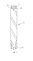
- FIG.2 is a perspective view illustrating a rotation shaft of FIG.1
- FIG.3 is a cross-sectional view taken along line I-I' of FIG.2 .
- a motor (100) includes a rotation shaft (6), a sensing magnet (7), a rotor (10) and a stator (20).
- the motor (100) may further comprise a motor housing (5).
- the motor housing (5) takes a shape of an upper surface-opened cylinder, and is fixed therein by the stator (20).
- the shape of the motor housing (5) may be differently formed according to types of a used motor, and may be formed in a pair as illustrated in FIG. 1 , in case of being employed for a motor used for a DCT (Dual-Clutch Transmission).
- DCT Direct-Clutch Transmission
- the DCT uses two separate clutches for odd and even gear sets unlike a single clutch transmission mounted on a manual transmission vehicle.
- the larger outer clutch drives the odd numbered (1, 3, 5) gears, whilst the smaller inner clutch drives the even (2, 4, 6) numbered gears by applying an engine's torque to one clutch.
- the DCTs characteristically provide convenient operability and smooth shift quality as in an automatic transmission vehicle, and has higher fuel efficiency than that of a manual transmission vehicle.
- the DCT includes a dual clutch formed with two clutches, a transmission control unit setting each shift by receiving a power from the dual clutch, a clutch actuator controlling each clutch of the dual clutch, a shift actuator performing the gear shift by applying selecting and shifting manipulations to the transmission control unit, and an electronic control unit electronically controlling the clutch actuator and the gear shift actuator by receiving various pieces of information including vehicle speed and gear shift command.
- the rotation shaft (6) becomes a rotation center of the rotor (10).
- the rotation shaft (6) takes a shape of a cylinder, and is formed at a bottom periphery of the rotation shaft (6) with a set of teeth (6a) for transmitting a power.
- the rotation shaft (6) is formed at an upper surface (6b) with an alignment groove (6c) concavely formed from the upper surface (6b).
- the alignment groove (6c) may take a shape of a circle, when viewed from a top plan.
- a diameter of the alignment groove (6c) is formed smaller than a diameter of the rotation shaft (6), and the alignment groove (6c) is formed with a depth of less than approximately 0.3mm, when measured from the upper surface (6b) of the rotation shaft (6).
- a center of the alignment groove (6c) is formed same as a rotation center of the rotation shaft (6).
- the depth of the alignment groove (6c) is less than approximately 0.3mm
- the depth of the alignment groove (6c) may be formed less than a height of a sensing magnet (7, described later).
- the sensing magnet (7) is installed inside the alignment groove (6c) formed on the upper surface (6b) of the rotation shaft (6).
- a shape of the sensing magnet (7) corresponds to that of the alignment groove (6) to allow being inserted into the alignment groove (6c), and the sensing magnet (7) may be inserted or press-fitted into the alignment groove (6c).
- the sensing magnet (7) may take a cylindrical shape, for example.
- the sensing magnet (7) inserted or press-fitted into the alignment groove (6c) generates a magnetic field for sensing the revolution of the rotation shaft (6).
- An area opposite to the sensing magnet (7) inserted or press-fitted into the alignment groove (6c) is arranged with a sensing plate detecting the magnetic field generated from the sensing magnet (7).
- a height of the sensing magnet (7) may be formed higher than the depth of the alignment groove (6c), whereby the sensing magnet (7) is protruded from the upper surface of the rotation shaft (6) at a predetermined height.
- an adhesive may be interposed between an inner surface of the rotation shaft (6) formed by the alignment groove (6c) and the sensing magnet (7) in order to prevent the sensing magnet inserted or press-fitted into the alignment groove (6c) from being disengaged from the rotation shaft (6) when the rotation shaft (6) is rotated at a high speed.
- the sensing magnet (7) can be coupled to the rotation shaft (6) without any separate jig, because the sensing magnet (7) is inserted or press-fitted into the alignment groove (6c) having a center that matches to a rotation center of the rotation shaft (6).
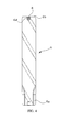
- FIG. 4 is a cross-sectional view illustrating a rotation shaft and a sensing magnet according to another exemplary embodiment of the present disclosure.
- a rotation shaft (6) becomes a rotation center of a rotor (10).
- the rotation shaft (6) takes a shape of a cylinder, and is formed at a bottom periphery of the rotation shaft (6) with a set of teeth (6a) for transmitting a power.
- the rotation shaft (6) is formed at an upper surface (6b) with an alignment groove (6d) concavely formed from the upper surface (6b).
- the alignment groove (6d) may take a shape of a circle, when viewed from a top plan.
- a diameter of the alignment groove (6d) is formed smaller than a diameter of the rotation shaft (6), and the alignment groove (6d) may be formed higher than a height of a sensing magnet (8, described later), when measured from the upper surface (6b) of the rotation shaft (6). Furthermore, the alignment groove (6d) may be formed with a same depth as that of the sensing magnet (8).
- a center of the alignment groove (6d) matches to a rotation center of the rotation shaft (6).
- the sensing magnet (8) is installed inside the alignment groove (6d) formed on the upper surface (6b) of the rotation shaft (6).
- a shape of the sensing magnet (8) is formed to correspond to that of the alignment groove (6d) such that the sensing magnet (8) can be completely inserted into the alignment groove (6d), and the sensing magnet (8) may be inserted or press-fitted into the alignment groove (6d).
- a height of the sensing magnet (8) is substantially same as a depth of the alignment groove (6d), and an upper surface of the sensing magnet (8) and the upper surface (6b) of the rotation shaft (6) are substantially arranged on a same planar surface.
- the sensing magnet (8) inserted or press-fitted into the alignment groove (6d) generates a magnetic field for sensing the revolution of the rotation shaft (6).
- An area opposite to the sensing magnet (8) inserted or press-fitted into the alignment groove (6d) is arranged with a sensing plate detecting the magnetic field generated from the sensing magnet (8).
- the sensing magnet (8) is arranged inside the alignment groove (6d) arranged on the upper surface (6b) of the rotation shaft (6), an entire thickness of the motor (100) can be further reduced in comparison with a case where the sensing magnet (8) is protruded from the upper surface (6b) of the rotation shaft (6). Furthermore, size of the sensing magnet (8) can be reduced to decrease the manufacturing cost of the sensing magnet (8) formed with a high-priced rare earth, whereby productivity can be improved.
- an adhesive may be interposed between an inner surface of the rotation shaft (6) formed by the alignment groove (6d) and the sensing magnet (8) in order to prevent the sensing magnet (8) inserted or press-fitted into the alignment groove (6d) from being disengaged from the rotation shaft (6) when the rotation shaft (6) is rotated at a high speed.
- the sensing magnet (8) can be coupled to the rotation shaft (6) without any separate jig, because the sensing magnet (8) is inserted or press-fitted into the alignment groove (6d) having a center that matches to a rotation center of the rotation shaft (6).
- the rotor (10) includes a core member (10a) coupled to a periphery of the rotation shaft (6) and a magnet (10b) press-fitted into the core member (10a).
- the rotor (10) is rotated by interaction with a stator (20, described later).
- stator (20) is arranged about the rotor (10), and the stator (20) takes a shape wrapping the rotor (10).
- the electromagnetic force generated from a coil (40) wound on the stator (20) interacts with the magnetic field generated from the magnet (10b) of the rotor (10) to generate a rotary power of the rotor (10).
- the stator (20) is arranged an inner surface of a motor housing (5), and the stator (20) is arranged at a support unit formed at an inner circumferential surface of the motor housing (5).
- the stator (20) may be formed by stacking a plurality of silicon steel plate sheets, each having a thickness of approximately 1 mm.
- Each of the stacked silicon steel plate sheets forming the stator (20) takes a shape of a ring, when viewed from a top plan, and an inner circumferential surface of the ringshaped silicon steel plate is formed with a plurality of core units (not shown) each protruded at an equal gap to a direction facing a center of the rotor (10). Furthermore, a distal end of each core unit is formed with a pole unit (not shown) extended to both sides of the core units.
- the number of core units may increase or decrease in response to size and output of the motor, and the core units may be formed with a multiple of three.
- stator (20) includes an insulator (30) for electrical insulation from the coil (40).
- the motor according to the exemplary embodiment of the present disclosure has an industrial applicability in that it can accurately match a rotation center of a sensing magnet and a rotation center of a rotation shaft by arranging the sensing magnet arranged at a distal end of the rotation shaft for sensing a rotation speed of the rotation shaft, using an alignment groove formed at a distal end of the rotation shaft, to more accurately sense a revolution of the rotation shaft in response to the sensing magnet.
Landscapes
- Engineering & Computer Science (AREA)
- Power Engineering (AREA)
- Microelectronics & Electronic Packaging (AREA)
Abstract
Description
- The present disclosure relates to a motor configured to be used for a dual clutch transmission and the like.
- In general, a motor is an apparatus converting an electric energy to a rotary power.
- The motor includes a rotation shaft, a rotor including a magnet formed on the rotation shaft, and a stator including a coil generating an electromagnetic force in response to a current generated from the coil arranged about the rotor.
- Some of the motors where revolution and rotation speed act as important factors may be arranged at a distal end of a rotation shaft with a sensing magnet counting the revolution of the rotation shaft, and a sensing plate calculating an actual revolution of the rotation shaft and rotation speed by detecting a magnetic field generated from the sensing magnet may be arranged at a position opposite to the sensing magnet.
- In general, in a case the sensing magnet is arranged at the distal end of the rotation shaft having a flat cross-section, a rotation center of the rotation shaft and a rotation center of the sensing magnet may be adjacently arranged using a jig, but it is difficult to match the rotation center of the rotation shaft and the rotation center of the sensing magnet, even if the jig is used, whereby the sensing magnet is eccentrically rotated from the distal end of the rotation shaft.
- Another disadvantage is that the number of assembly processes increases because the sensing magnet is arranged at the distal end of the rotation shaft using the jig.
- Particularly, in a case the sensing magnet is eccentrically rotated from the distal end of the rotation shaft, sensing errors on the revolution and rotation speed frequently occur due to difficulty in accurately detecting the magnetic field generated from the sensing magnet.
- The present disclosure is directed to cope with the abovementioned problems/disadvantages and it is an object of the present disclosure to provide a motor configured to accurately detect a revolution and a rotation speed of a motor by accurately matching a rotation center of a rotation shaft and a rotation center of a sensing magnet without a separate alignment process.
- In one general aspect of the present disclosure, there is provided a motor, the motor comprising:
- a rotation shaft having an alignment groove at a distal end of one side from a rotation center;
- a sensing magnet disposed at the distal end of one side of the rotation shaft by being mounted on the alignment groove of the rotation shaft;
- a rotor including a magnet coupled to a periphery of the rotation shaft; and
- a stator including a core wrapping an ambient of the rotor and wound with a coil.
- Preferably, but not necessarily, the sensing magnet may take a shape of a pillar, and a rotation center of the sensing magnet may match a rotation center of the rotation shaft. Preferably, but not necessarily, the sensing magnet may take a shape of a cylinder.
- Preferably, but not necessarily, the motor may further comprise an adhesive between the sensing magnet and the rotation shaft.
- Preferably, but not necessarily, a height of the sensing magnet may be greater than a depth of the alignment groove, and the sensing magnet may be protruded from the distal end of the rotation shaft.
- Preferably, but not necessarily, the depth of the alignment groove may be less than 0.3mm.
- Preferably, but not necessarily, the depth of the alignment groove may be greater than the height of the sensing magnet.
- Preferably, but not necessarily, an upper surface of the sensing magnet may be arranged on a same planar surface as that of the distal end of one side of the rotation shaft.
- In an advantageous effect, a motor according to an exemplary embodiment of the present disclosure can accurately match a rotation center of a sensing magnet and a rotation center of a rotation shaft by arranging the sensing magnet arranged at a distal end of the rotation shaft for sensing a rotation speed of the rotation shaft, using an alignment groove formed at a distal end of the rotation shaft, to more accurately sense a revolution of the rotation shaft in response to the sensing magnet.
- In another advantageous effect, a motor according to an exemplary embodiment of the present disclosure can shorten an entire assembly process by omitting a process using a separate jig.
-
-
FIG.1 is a cross-sectional view illustrating a motor according to an exemplary embodiment of the present disclosure. -
FIG.2 is a perspective view illustrating a rotation shaft ofFIG.1 . -
FIG.3 is a cross-sectional view taken along line I-I' ofFIG.2 . -
FIG. 4 is a cross-sectional view illustrating a rotation shaft and a sensing magnet according to another exemplary embodiment of the present disclosure. - Now, a motor according to exemplary embodiments of the present disclosure will be described in detail with reference to the accompanying drawings.
- In describing the present disclosure, detailed descriptions of constructions or processes known in the art may be omitted to avoid obscuring appreciation of the invention by a person of ordinary skill in the art with unnecessary detail regarding such known constructions and functions. In the drawings, the size and relative sizes of layers, regions and/or other elements may be exaggerated or reduced for clarity. Accordingly, the meaning of specific terms or words used in the specification and claims should not be limited to the literal or commonly employed sense, but should be construed or may be different in accordance with the intention of a user or an operator and customary usages. Therefore, the definition of the specific terms or words should be based on the contents across the specification.
-
FIG.1 is a cross-sectional view illustrating a motor according to an exemplary embodiment of the present disclosure,FIG.2 is a perspective view illustrating a rotation shaft ofFIG.1 , andFIG.3 is a cross-sectional view taken along line I-I' ofFIG.2 . - Referring to
FIGS. 1 ,2 and3 , a motor (100) includes a rotation shaft (6), a sensing magnet (7), a rotor (10) and a stator (20). In addition, the motor (100) may further comprise a motor housing (5). - The motor housing (5) takes a shape of an upper surface-opened cylinder, and is fixed therein by the stator (20).
- The shape of the motor housing (5) may be differently formed according to types of a used motor, and may be formed in a pair as illustrated in
FIG. 1 , in case of being employed for a motor used for a DCT (Dual-Clutch Transmission). - The DCT uses two separate clutches for odd and even gear sets unlike a single clutch transmission mounted on a manual transmission vehicle.
- In DCTs where the two clutches are arranged concentrically, the larger outer clutch drives the odd numbered (1, 3, 5) gears, whilst the smaller inner clutch drives the even (2, 4, 6) numbered gears by applying an engine's torque to one clutch.
- The DCTs characteristically provide convenient operability and smooth shift quality as in an automatic transmission vehicle, and has higher fuel efficiency than that of a manual transmission vehicle.
- The DCT includes a dual clutch formed with two clutches, a transmission control unit setting each shift by receiving a power from the dual clutch, a clutch actuator controlling each clutch of the dual clutch, a shift actuator performing the gear shift by applying selecting and shifting manipulations to the transmission control unit, and an electronic control unit electronically controlling the clutch actuator and the gear shift actuator by receiving various pieces of information including vehicle speed and gear shift command.
- The rotation shaft (6) becomes a rotation center of the rotor (10).
- The rotation shaft (6) takes a shape of a cylinder, and is formed at a bottom periphery of the rotation shaft (6) with a set of teeth (6a) for transmitting a power.
- Referring to
FIGS. 2 and3 , the rotation shaft (6) is formed at an upper surface (6b) with an alignment groove (6c) concavely formed from the upper surface (6b). The alignment groove (6c) may take a shape of a circle, when viewed from a top plan. - A diameter of the alignment groove (6c) is formed smaller than a diameter of the rotation shaft (6), and the alignment groove (6c) is formed with a depth of less than approximately 0.3mm, when measured from the upper surface (6b) of the rotation shaft (6). A center of the alignment groove (6c) is formed same as a rotation center of the rotation shaft (6).
- Although the exemplary embodiment of the present disclosure has described and explained that the depth of the alignment groove (6c) is less than approximately 0.3mm, the depth of the alignment groove (6c) may be formed less than a height of a sensing magnet (7, described later).
- The sensing magnet (7) is installed inside the alignment groove (6c) formed on the upper surface (6b) of the rotation shaft (6). A shape of the sensing magnet (7) corresponds to that of the alignment groove (6) to allow being inserted into the alignment groove (6c), and the sensing magnet (7) may be inserted or press-fitted into the alignment groove (6c).
- In the exemplary embodiment of the present disclosure, the sensing magnet (7) may take a cylindrical shape, for example.
- The sensing magnet (7) inserted or press-fitted into the alignment groove (6c) generates a magnetic field for sensing the revolution of the rotation shaft (6). An area opposite to the sensing magnet (7) inserted or press-fitted into the alignment groove (6c) is arranged with a sensing plate detecting the magnetic field generated from the sensing magnet (7).
- In the exemplary embodiment of the present disclosure, a height of the sensing magnet (7) may be formed higher than the depth of the alignment groove (6c), whereby the sensing magnet (7) is protruded from the upper surface of the rotation shaft (6) at a predetermined height.
- Meanwhile, an adhesive may be interposed between an inner surface of the rotation shaft (6) formed by the alignment groove (6c) and the sensing magnet (7) in order to prevent the sensing magnet inserted or press-fitted into the alignment groove (6c) from being disengaged from the rotation shaft (6) when the rotation shaft (6) is rotated at a high speed.
- In the exemplary embodiment of the present disclosure, the sensing magnet (7) can be coupled to the rotation shaft (6) without any separate jig, because the sensing magnet (7) is inserted or press-fitted into the alignment groove (6c) having a center that matches to a rotation center of the rotation shaft (6).
- Hence, even a simple insertion or press-fitting of the sensing magnet (7) into the alignment groove (6c) of rotation shaft (6) can accurately match the rotation center of the sensing magnet (7) to the rotation center of the rotation shaft (6), whereby a sensing error of revolution of the rotation shaft (6) caused by an installation position of the sensing magnet (7) can be restricted or prevented.
-
FIG. 4 is a cross-sectional view illustrating a rotation shaft and a sensing magnet according to another exemplary embodiment of the present disclosure. - Referring to
FIG.4 , a rotation shaft (6) becomes a rotation center of a rotor (10). - The rotation shaft (6) takes a shape of a cylinder, and is formed at a bottom periphery of the rotation shaft (6) with a set of teeth (6a) for transmitting a power.
- The rotation shaft (6) is formed at an upper surface (6b) with an alignment groove (6d) concavely formed from the upper surface (6b). The alignment groove (6d) may take a shape of a circle, when viewed from a top plan.
- A diameter of the alignment groove (6d) is formed smaller than a diameter of the rotation shaft (6), and the alignment groove (6d) may be formed higher than a height of a sensing magnet (8, described later), when measured from the upper surface (6b) of the rotation shaft (6). Furthermore, the alignment groove (6d) may be formed with a same depth as that of the sensing magnet (8).
- In the exemplary embodiment of the present disclosure, a center of the alignment groove (6d) matches to a rotation center of the rotation shaft (6).
- The sensing magnet (8) is installed inside the alignment groove (6d) formed on the upper surface (6b) of the rotation shaft (6). A shape of the sensing magnet (8) is formed to correspond to that of the alignment groove (6d) such that the sensing magnet (8) can be completely inserted into the alignment groove (6d), and the sensing magnet (8) may be inserted or press-fitted into the alignment groove (6d).
- In the exemplary embodiment of the present disclosure, a height of the sensing magnet (8) is substantially same as a depth of the alignment groove (6d), and an upper surface of the sensing magnet (8) and the upper surface (6b) of the rotation shaft (6) are substantially arranged on a same planar surface.
- The sensing magnet (8) inserted or press-fitted into the alignment groove (6d) generates a magnetic field for sensing the revolution of the rotation shaft (6). An area opposite to the sensing magnet (8) inserted or press-fitted into the alignment groove (6d) is arranged with a sensing plate detecting the magnetic field generated from the sensing magnet (8).
- In the exemplary embodiment of the present disclosure, because the sensing magnet (8) is arranged inside the alignment groove (6d) arranged on the upper surface (6b) of the rotation shaft (6), an entire thickness of the motor (100) can be further reduced in comparison with a case where the sensing magnet (8) is protruded from the upper surface (6b) of the rotation shaft (6). Furthermore, size of the sensing magnet (8) can be reduced to decrease the manufacturing cost of the sensing magnet (8) formed with a high-priced rare earth, whereby productivity can be improved.
- Meanwhile, an adhesive may be interposed between an inner surface of the rotation shaft (6) formed by the alignment groove (6d) and the sensing magnet (8) in order to prevent the sensing magnet (8) inserted or press-fitted into the alignment groove (6d) from being disengaged from the rotation shaft (6) when the rotation shaft (6) is rotated at a high speed.
- In the exemplary embodiment of the present disclosure, the sensing magnet (8) can be coupled to the rotation shaft (6) without any separate jig, because the sensing magnet (8) is inserted or press-fitted into the alignment groove (6d) having a center that matches to a rotation center of the rotation shaft (6).
- Hence, even a simple insertion or press-fitting of the sensing magnet (8) into the alignment groove (6d) of rotation shaft (6) can accurately match the rotation center of the sensing magnet (8) to the rotation center of the rotation shaft (6), whereby a sensing error of revolution of the rotation shaft (6) caused by an installation position of the sensing magnet (8) can be restricted or prevented.
- The rotor (10) includes a core member (10a) coupled to a periphery of the rotation shaft (6) and a magnet (10b) press-fitted into the core member (10a). The rotor (10) is rotated by interaction with a stator (20, described later).
- Referring to
FIG.1 again, the stator (20) is arranged about the rotor (10), and the stator (20) takes a shape wrapping the rotor (10). - The electromagnetic force generated from a coil (40) wound on the stator (20) interacts with the magnetic field generated from the magnet (10b) of the rotor (10) to generate a rotary power of the rotor (10).
- The stator (20) is arranged an inner surface of a motor housing (5), and the stator (20) is arranged at a support unit formed at an inner circumferential surface of the motor housing (5).
- The stator (20) may be formed by stacking a plurality of silicon steel plate sheets, each having a thickness of approximately 1 mm.
- Each of the stacked silicon steel plate sheets forming the stator (20) takes a shape of a ring, when viewed from a top plan, and an inner circumferential surface of the ringshaped silicon steel plate is formed with a plurality of core units (not shown) each protruded at an equal gap to a direction facing a center of the rotor (10). Furthermore, a distal end of each core unit is formed with a pole unit (not shown) extended to both sides of the core units. In the exemplary embodiment of the present disclosure, the number of core units may increase or decrease in response to size and output of the motor, and the core units may be formed with a multiple of three.
- Meanwhile, the stator (20) includes an insulator (30) for electrical insulation from the coil (40).
- As apparent from the foregoing, the motor according to the exemplary embodiment of the present disclosure has an industrial applicability in that it can accurately match a rotation center of a sensing magnet and a rotation center of a rotation shaft by arranging the sensing magnet arranged at a distal end of the rotation shaft for sensing a rotation speed of the rotation shaft, using an alignment groove formed at a distal end of the rotation shaft, to more accurately sense a revolution of the rotation shaft in response to the sensing magnet.
- Although embodiments have been described with reference to a number of illustrative embodiments thereof, it should be understood that numerous other modifications and embodiments can be devised by those skilled in the art that will fall within the spirit and scope of the principles of this disclosure. More particularly, various variations and modifications are possible in the component parts and/or arrangements of the subject combination arrangement within the scope of the disclosure, the drawings and the appended claims.
Claims (8)
- A motor (100), the motor (100) including a rotation shaft, a stator including a magnet formed on the rotation shaft and a coil wound on a core arranged about a rotor to generate an electromagnetic force in response to an applied current, the motor characterized by:a rotation shaft (6) having an alignment groove (6c) at a distal end of one side from a rotation center;a sensing magnet (7) disposed at the distal end of one side of the rotation shaft (6) by being mounted on the alignment groove (6c) of the rotation shaft (6);a rotor (10) including a magnet (10b) coupled to a periphery of the rotation shaft (6); anda stator (20) including a core wrapping an ambient of the rotor (10) and wound with a coil.
- The motor of claim 1, characterize in that the sensing magnet (7) takes a shape of a pillar, and a rotation center of the sensing magnet (7) matches a rotation center of the rotation shaft (6).
- The motor of claim 2, characterize in that the sensing magnet (7) takes a shape of a cylinder.
- The motor of claim 1, further characterized by an adhesive between the sensing magnet (7) and the rotation shaft (6).
- The motor of claim 1, characterize in that a height of the sensing magnet (7) is greater than a depth of the alignment groove (6c), and the sensing magnet (7) is protruded from the distal end of the rotation shaft (6).
- The motor of claim 1, characterize in that the depth of the alignment groove (6c) is less than 0.3mm.
- The motor of claim 1, characterize in that the depth of the alignment groove (6c) is greater than the height of the sensing magnet (7).
- The motor of claim 7, characterize in that an upper surface of the sensing magnet (7) is arranged on a same planar surface as that of the distal end of one side of the rotation shaft (6).
Applications Claiming Priority (1)
| Application Number | Priority Date | Filing Date | Title |
|---|---|---|---|
| KR1020120067329A KR101940683B1 (en) | 2012-06-22 | 2012-06-22 | Motor |
Publications (3)
| Publication Number | Publication Date |
|---|---|
| EP2677642A2 true EP2677642A2 (en) | 2013-12-25 |
| EP2677642A3 EP2677642A3 (en) | 2017-09-27 |
| EP2677642B1 EP2677642B1 (en) | 2019-07-31 |
Family
ID=48782867
Family Applications (1)
| Application Number | Title | Priority Date | Filing Date |
|---|---|---|---|
| EP13173111.9A Active EP2677642B1 (en) | 2012-06-22 | 2013-06-20 | Motor with magnet sensor |
Country Status (4)
| Country | Link |
|---|---|
| US (1) | US9583994B2 (en) |
| EP (1) | EP2677642B1 (en) |
| KR (1) | KR101940683B1 (en) |
| CN (1) | CN103516141B (en) |
Cited By (5)
| Publication number | Priority date | Publication date | Assignee | Title |
|---|---|---|---|---|
| FR3025667A1 (en) * | 2014-09-10 | 2016-03-11 | Bosch Gmbh Robert | ELECTRIC MACHINE COMPRISING AN INDUCTURE |
| WO2016155733A1 (en) * | 2015-04-02 | 2016-10-06 | Bühler Motor GmbH | Magnet sensor |
| WO2016155734A1 (en) * | 2015-04-02 | 2016-10-06 | Bühler Motor GmbH | Magnet sensor |
| WO2016155732A1 (en) * | 2015-04-02 | 2016-10-06 | Bühler Motor GmbH | Magnet sensor |
| FR3079975A1 (en) * | 2018-04-10 | 2019-10-11 | Schaeffler Technologies AG & Co. KG | SYSTEM FOR CONTROLLING THE SUSPENSION OF A VEHICLE |
Families Citing this family (4)
| Publication number | Priority date | Publication date | Assignee | Title |
|---|---|---|---|---|
| CN103825408A (en) * | 2014-02-28 | 2014-05-28 | 深圳市大疆创新科技有限公司 | Motor, cloud deck using the motor and shooting device using the cloud deck |
| DE102016226223A1 (en) * | 2016-12-27 | 2018-06-28 | Robert Bosch Gmbh | Magnetic holder for attaching a sensor magnet to a motor shaft |
| EP3731376A1 (en) | 2019-04-24 | 2020-10-28 | Black & Decker Inc. | Outer rotor brushless motor stator mount |
| CN114825757A (en) | 2021-01-18 | 2022-07-29 | 浙江三花汽车零部件有限公司 | Drive device |
Family Cites Families (16)
| Publication number | Priority date | Publication date | Assignee | Title |
|---|---|---|---|---|
| US2323945A (en) * | 1940-02-01 | 1943-07-13 | A F Dormeyer Mfg Co | Motor |
| US4125821A (en) * | 1977-08-05 | 1978-11-14 | Denki Onkyo Company, Limited | Potentiometer providing a non-linear output |
| US6771065B2 (en) | 2001-02-26 | 2004-08-03 | Woodward Governor Company | Line hall effect detector and method of sensing angular position particularly suited for electrical rotary actuator |
| KR100425721B1 (en) * | 2001-06-25 | 2004-04-03 | 엘지전자 주식회사 | Apparatus for sensing rotor position of brushless motor |
| DE102004059181A1 (en) * | 2004-12-08 | 2006-06-29 | Siemens Ag | Generalized rotary electrical machine, has end-of-shaft encoder with speed sensor mounted on circuit board located in end plate of machine |
| JP4704065B2 (en) * | 2005-02-22 | 2011-06-15 | Ntn株式会社 | Bearing with rotation detector |
| US7988363B2 (en) * | 2005-02-22 | 2011-08-02 | Ntn Corporation | Bearing with rotation detection device |
| KR20060101998A (en) * | 2005-03-22 | 2006-09-27 | 현대모비스 주식회사 | Rotor position sensing device of AC motor |
| KR20070009170A (en) | 2005-07-15 | 2007-01-18 | 엘지전자 주식회사 | motor |
| DE102006032780A1 (en) * | 2006-07-14 | 2008-01-17 | Siemens Ag | Electric motor drive for vehicle, has speed sensor that is arranged at side of rotor, and magnetoresistive sensor that is arranged at side of stator, where speed sensor is connected with rotor shaft as single-piece |
| EP2141785B1 (en) * | 2008-07-04 | 2019-08-28 | Mabuchi Motor Co., Ltd. | Sensor magnet holder, motor having the holder incorporated therein, and method of manufacturing the motor |
| KR101550920B1 (en) * | 2009-01-23 | 2015-09-07 | 엘지이노텍 주식회사 | Motor |
| DE102010023813A1 (en) * | 2010-06-15 | 2011-12-15 | Maxon Motor Ag | Small electric motor |
| JP5604356B2 (en) | 2011-04-07 | 2014-10-08 | 株式会社日立製作所 | Elevator hoisting machine and elevator device |
| CN102361370B (en) | 2011-10-29 | 2013-08-07 | 重庆大学 | Integrated motor rotating speed measuring mechanism of sensor arranged in motor end cover |
| US9427172B2 (en) * | 2011-12-30 | 2016-08-30 | Mediguide Ltd. | Roll detection and six degrees of freedom sensor assembly |
-
2012
- 2012-06-22 KR KR1020120067329A patent/KR101940683B1/en active Active
-
2013
- 2013-06-20 EP EP13173111.9A patent/EP2677642B1/en active Active
- 2013-06-21 US US13/923,819 patent/US9583994B2/en active Active
- 2013-06-24 CN CN201310253174.4A patent/CN103516141B/en active Active
Non-Patent Citations (1)
| Title |
|---|
| None |
Cited By (5)
| Publication number | Priority date | Publication date | Assignee | Title |
|---|---|---|---|---|
| FR3025667A1 (en) * | 2014-09-10 | 2016-03-11 | Bosch Gmbh Robert | ELECTRIC MACHINE COMPRISING AN INDUCTURE |
| WO2016155733A1 (en) * | 2015-04-02 | 2016-10-06 | Bühler Motor GmbH | Magnet sensor |
| WO2016155734A1 (en) * | 2015-04-02 | 2016-10-06 | Bühler Motor GmbH | Magnet sensor |
| WO2016155732A1 (en) * | 2015-04-02 | 2016-10-06 | Bühler Motor GmbH | Magnet sensor |
| FR3079975A1 (en) * | 2018-04-10 | 2019-10-11 | Schaeffler Technologies AG & Co. KG | SYSTEM FOR CONTROLLING THE SUSPENSION OF A VEHICLE |
Also Published As
| Publication number | Publication date |
|---|---|
| EP2677642B1 (en) | 2019-07-31 |
| KR101940683B1 (en) | 2019-04-12 |
| US9583994B2 (en) | 2017-02-28 |
| US20130342086A1 (en) | 2013-12-26 |
| EP2677642A3 (en) | 2017-09-27 |
| KR20140003672A (en) | 2014-01-10 |
| CN103516141A (en) | 2014-01-15 |
| CN103516141B (en) | 2017-05-10 |
Similar Documents
| Publication | Publication Date | Title |
|---|---|---|
| US9583994B2 (en) | Motor with shaft integrated sensing magnet | |
| EP2526609B1 (en) | Coil form for mounting on a magnet core, magnet core for reluctance resolvers, and method of manufacture | |
| CN102857045B (en) | The manufacture method of stator, stator and motor | |
| US7705494B2 (en) | Electric motor | |
| EP3010127B1 (en) | Motor | |
| JP5741826B2 (en) | motor | |
| KR102120314B1 (en) | Rotor and motor including the same | |
| CN111245164B (en) | Rotating electric machine and method for manufacturing same | |
| US20210234413A1 (en) | Stator and motor comprising same | |
| JP5629955B2 (en) | Rotation angle detection or rotation synchronization device | |
| JP2012235652A (en) | Rotor and rotating electric machine | |
| JP2021513312A (en) | Rotor and motor equipped with it | |
| CN103580343B (en) | Motor | |
| JP2019092298A (en) | Stator, block of the stator, and rotary electric machine | |
| KR102874999B1 (en) | Motor | |
| KR20200025405A (en) | Motor | |
| JP2014204495A (en) | Rotary electric machine and manufacturing method thereof | |
| KR101939395B1 (en) | Motor | |
| KR101911723B1 (en) | Motor | |
| KR101332151B1 (en) | motor | |
| KR102040531B1 (en) | Motor | |
| US9915554B2 (en) | Terminal block structure and stator for resolver | |
| KR20180089173A (en) | Motor | |
| KR20190034935A (en) | Motor | |
| CN104769823B (en) | Stator cores for rotating electrical machines |
Legal Events
| Date | Code | Title | Description |
|---|---|---|---|
| PUAI | Public reference made under article 153(3) epc to a published international application that has entered the european phase |
Free format text: ORIGINAL CODE: 0009012 |
|
| AK | Designated contracting states |
Kind code of ref document: A2 Designated state(s): AL AT BE BG CH CY CZ DE DK EE ES FI FR GB GR HR HU IE IS IT LI LT LU LV MC MK MT NL NO PL PT RO RS SE SI SK SM TR |
|
| AX | Request for extension of the european patent |
Extension state: BA ME |
|
| RAP1 | Party data changed (applicant data changed or rights of an application transferred) |
Owner name: LG INNOTEK CO., LTD. |
|
| PUAL | Search report despatched |
Free format text: ORIGINAL CODE: 0009013 |
|
| AK | Designated contracting states |
Kind code of ref document: A3 Designated state(s): AL AT BE BG CH CY CZ DE DK EE ES FI FR GB GR HR HU IE IS IT LI LT LU LV MC MK MT NL NO PL PT RO RS SE SI SK SM TR |
|
| AX | Request for extension of the european patent |
Extension state: BA ME |
|
| RIC1 | Information provided on ipc code assigned before grant |
Ipc: H02K 29/08 20060101AFI20170824BHEP Ipc: H02K 29/06 20060101ALI20170824BHEP Ipc: H02K 7/00 20060101ALN20170824BHEP Ipc: H02K 29/14 20060101ALI20170824BHEP |
|
| STAA | Information on the status of an ep patent application or granted ep patent |
Free format text: STATUS: REQUEST FOR EXAMINATION WAS MADE |
|
| 17P | Request for examination filed |
Effective date: 20180322 |
|
| RBV | Designated contracting states (corrected) |
Designated state(s): AL AT BE BG CH CY CZ DE DK EE ES FI FR GB GR HR HU IE IS IT LI LT LU LV MC MK MT NL NO PL PT RO RS SE SI SK SM TR |
|
| GRAP | Despatch of communication of intention to grant a patent |
Free format text: ORIGINAL CODE: EPIDOSNIGR1 |
|
| STAA | Information on the status of an ep patent application or granted ep patent |
Free format text: STATUS: GRANT OF PATENT IS INTENDED |
|
| INTG | Intention to grant announced |
Effective date: 20190222 |
|
| GRAS | Grant fee paid |
Free format text: ORIGINAL CODE: EPIDOSNIGR3 |
|
| GRAA | (expected) grant |
Free format text: ORIGINAL CODE: 0009210 |
|
| STAA | Information on the status of an ep patent application or granted ep patent |
Free format text: STATUS: THE PATENT HAS BEEN GRANTED |
|
| AK | Designated contracting states |
Kind code of ref document: B1 Designated state(s): AL AT BE BG CH CY CZ DE DK EE ES FI FR GB GR HR HU IE IS IT LI LT LU LV MC MK MT NL NO PL PT RO RS SE SI SK SM TR |
|
| REG | Reference to a national code |
Ref country code: CH Ref legal event code: EP Ref country code: GB Ref legal event code: FG4D |
|
| REG | Reference to a national code |
Ref country code: AT Ref legal event code: REF Ref document number: 1161990 Country of ref document: AT Kind code of ref document: T Effective date: 20190815 |
|
| REG | Reference to a national code |
Ref country code: IE Ref legal event code: FG4D Ref country code: NL Ref legal event code: FP |
|
| REG | Reference to a national code |
Ref country code: DE Ref legal event code: R096 Ref document number: 602013058416 Country of ref document: DE |
|
| REG | Reference to a national code |
Ref country code: LT Ref legal event code: MG4D |
|
| REG | Reference to a national code |
Ref country code: AT Ref legal event code: MK05 Ref document number: 1161990 Country of ref document: AT Kind code of ref document: T Effective date: 20190731 |
|
| PG25 | Lapsed in a contracting state [announced via postgrant information from national office to epo] |
Ref country code: NO Free format text: LAPSE BECAUSE OF FAILURE TO SUBMIT A TRANSLATION OF THE DESCRIPTION OR TO PAY THE FEE WITHIN THE PRESCRIBED TIME-LIMIT Effective date: 20191031 Ref country code: SE Free format text: LAPSE BECAUSE OF FAILURE TO SUBMIT A TRANSLATION OF THE DESCRIPTION OR TO PAY THE FEE WITHIN THE PRESCRIBED TIME-LIMIT Effective date: 20190731 Ref country code: BG Free format text: LAPSE BECAUSE OF FAILURE TO SUBMIT A TRANSLATION OF THE DESCRIPTION OR TO PAY THE FEE WITHIN THE PRESCRIBED TIME-LIMIT Effective date: 20191031 Ref country code: HR Free format text: LAPSE BECAUSE OF FAILURE TO SUBMIT A TRANSLATION OF THE DESCRIPTION OR TO PAY THE FEE WITHIN THE PRESCRIBED TIME-LIMIT Effective date: 20190731 Ref country code: FI Free format text: LAPSE BECAUSE OF FAILURE TO SUBMIT A TRANSLATION OF THE DESCRIPTION OR TO PAY THE FEE WITHIN THE PRESCRIBED TIME-LIMIT Effective date: 20190731 Ref country code: LT Free format text: LAPSE BECAUSE OF FAILURE TO SUBMIT A TRANSLATION OF THE DESCRIPTION OR TO PAY THE FEE WITHIN THE PRESCRIBED TIME-LIMIT Effective date: 20190731 Ref country code: PT Free format text: LAPSE BECAUSE OF FAILURE TO SUBMIT A TRANSLATION OF THE DESCRIPTION OR TO PAY THE FEE WITHIN THE PRESCRIBED TIME-LIMIT Effective date: 20191202 Ref country code: AT Free format text: LAPSE BECAUSE OF FAILURE TO SUBMIT A TRANSLATION OF THE DESCRIPTION OR TO PAY THE FEE WITHIN THE PRESCRIBED TIME-LIMIT Effective date: 20190731 |
|
| PG25 | Lapsed in a contracting state [announced via postgrant information from national office to epo] |
Ref country code: ES Free format text: LAPSE BECAUSE OF FAILURE TO SUBMIT A TRANSLATION OF THE DESCRIPTION OR TO PAY THE FEE WITHIN THE PRESCRIBED TIME-LIMIT Effective date: 20190731 Ref country code: AL Free format text: LAPSE BECAUSE OF FAILURE TO SUBMIT A TRANSLATION OF THE DESCRIPTION OR TO PAY THE FEE WITHIN THE PRESCRIBED TIME-LIMIT Effective date: 20190731 Ref country code: LV Free format text: LAPSE BECAUSE OF FAILURE TO SUBMIT A TRANSLATION OF THE DESCRIPTION OR TO PAY THE FEE WITHIN THE PRESCRIBED TIME-LIMIT Effective date: 20190731 Ref country code: GR Free format text: LAPSE BECAUSE OF FAILURE TO SUBMIT A TRANSLATION OF THE DESCRIPTION OR TO PAY THE FEE WITHIN THE PRESCRIBED TIME-LIMIT Effective date: 20191101 Ref country code: IS Free format text: LAPSE BECAUSE OF FAILURE TO SUBMIT A TRANSLATION OF THE DESCRIPTION OR TO PAY THE FEE WITHIN THE PRESCRIBED TIME-LIMIT Effective date: 20191130 Ref country code: RS Free format text: LAPSE BECAUSE OF FAILURE TO SUBMIT A TRANSLATION OF THE DESCRIPTION OR TO PAY THE FEE WITHIN THE PRESCRIBED TIME-LIMIT Effective date: 20190731 |
|
| PG25 | Lapsed in a contracting state [announced via postgrant information from national office to epo] |
Ref country code: TR Free format text: LAPSE BECAUSE OF FAILURE TO SUBMIT A TRANSLATION OF THE DESCRIPTION OR TO PAY THE FEE WITHIN THE PRESCRIBED TIME-LIMIT Effective date: 20190731 |
|
| PG25 | Lapsed in a contracting state [announced via postgrant information from national office to epo] |
Ref country code: RO Free format text: LAPSE BECAUSE OF FAILURE TO SUBMIT A TRANSLATION OF THE DESCRIPTION OR TO PAY THE FEE WITHIN THE PRESCRIBED TIME-LIMIT Effective date: 20190731 Ref country code: PL Free format text: LAPSE BECAUSE OF FAILURE TO SUBMIT A TRANSLATION OF THE DESCRIPTION OR TO PAY THE FEE WITHIN THE PRESCRIBED TIME-LIMIT Effective date: 20190731 Ref country code: EE Free format text: LAPSE BECAUSE OF FAILURE TO SUBMIT A TRANSLATION OF THE DESCRIPTION OR TO PAY THE FEE WITHIN THE PRESCRIBED TIME-LIMIT Effective date: 20190731 Ref country code: IT Free format text: LAPSE BECAUSE OF FAILURE TO SUBMIT A TRANSLATION OF THE DESCRIPTION OR TO PAY THE FEE WITHIN THE PRESCRIBED TIME-LIMIT Effective date: 20190731 Ref country code: DK Free format text: LAPSE BECAUSE OF FAILURE TO SUBMIT A TRANSLATION OF THE DESCRIPTION OR TO PAY THE FEE WITHIN THE PRESCRIBED TIME-LIMIT Effective date: 20190731 |
|
| PG25 | Lapsed in a contracting state [announced via postgrant information from national office to epo] |
Ref country code: IS Free format text: LAPSE BECAUSE OF FAILURE TO SUBMIT A TRANSLATION OF THE DESCRIPTION OR TO PAY THE FEE WITHIN THE PRESCRIBED TIME-LIMIT Effective date: 20200224 Ref country code: SM Free format text: LAPSE BECAUSE OF FAILURE TO SUBMIT A TRANSLATION OF THE DESCRIPTION OR TO PAY THE FEE WITHIN THE PRESCRIBED TIME-LIMIT Effective date: 20190731 Ref country code: SK Free format text: LAPSE BECAUSE OF FAILURE TO SUBMIT A TRANSLATION OF THE DESCRIPTION OR TO PAY THE FEE WITHIN THE PRESCRIBED TIME-LIMIT Effective date: 20190731 Ref country code: CZ Free format text: LAPSE BECAUSE OF FAILURE TO SUBMIT A TRANSLATION OF THE DESCRIPTION OR TO PAY THE FEE WITHIN THE PRESCRIBED TIME-LIMIT Effective date: 20190731 |
|
| REG | Reference to a national code |
Ref country code: DE Ref legal event code: R097 Ref document number: 602013058416 Country of ref document: DE |
|
| PLBE | No opposition filed within time limit |
Free format text: ORIGINAL CODE: 0009261 |
|
| STAA | Information on the status of an ep patent application or granted ep patent |
Free format text: STATUS: NO OPPOSITION FILED WITHIN TIME LIMIT |
|
| PG2D | Information on lapse in contracting state deleted |
Ref country code: IS |
|
| PG25 | Lapsed in a contracting state [announced via postgrant information from national office to epo] |
Ref country code: IS Free format text: LAPSE BECAUSE OF FAILURE TO SUBMIT A TRANSLATION OF THE DESCRIPTION OR TO PAY THE FEE WITHIN THE PRESCRIBED TIME-LIMIT Effective date: 20191030 |
|
| 26N | No opposition filed |
Effective date: 20200603 |
|
| PG25 | Lapsed in a contracting state [announced via postgrant information from national office to epo] |
Ref country code: SI Free format text: LAPSE BECAUSE OF FAILURE TO SUBMIT A TRANSLATION OF THE DESCRIPTION OR TO PAY THE FEE WITHIN THE PRESCRIBED TIME-LIMIT Effective date: 20190731 |
|
| PG25 | Lapsed in a contracting state [announced via postgrant information from national office to epo] |
Ref country code: MC Free format text: LAPSE BECAUSE OF FAILURE TO SUBMIT A TRANSLATION OF THE DESCRIPTION OR TO PAY THE FEE WITHIN THE PRESCRIBED TIME-LIMIT Effective date: 20190731 |
|
| REG | Reference to a national code |
Ref country code: CH Ref legal event code: PL |
|
| GBPC | Gb: european patent ceased through non-payment of renewal fee |
Effective date: 20200620 |
|
| PG25 | Lapsed in a contracting state [announced via postgrant information from national office to epo] |
Ref country code: LU Free format text: LAPSE BECAUSE OF NON-PAYMENT OF DUE FEES Effective date: 20200620 |
|
| REG | Reference to a national code |
Ref country code: BE Ref legal event code: MM Effective date: 20200630 |
|
| PG25 | Lapsed in a contracting state [announced via postgrant information from national office to epo] |
Ref country code: GB Free format text: LAPSE BECAUSE OF NON-PAYMENT OF DUE FEES Effective date: 20200620 Ref country code: CH Free format text: LAPSE BECAUSE OF NON-PAYMENT OF DUE FEES Effective date: 20200630 Ref country code: IE Free format text: LAPSE BECAUSE OF NON-PAYMENT OF DUE FEES Effective date: 20200620 Ref country code: LI Free format text: LAPSE BECAUSE OF NON-PAYMENT OF DUE FEES Effective date: 20200630 |
|
| PG25 | Lapsed in a contracting state [announced via postgrant information from national office to epo] |
Ref country code: BE Free format text: LAPSE BECAUSE OF NON-PAYMENT OF DUE FEES Effective date: 20200630 |
|
| PG25 | Lapsed in a contracting state [announced via postgrant information from national office to epo] |
Ref country code: MT Free format text: LAPSE BECAUSE OF FAILURE TO SUBMIT A TRANSLATION OF THE DESCRIPTION OR TO PAY THE FEE WITHIN THE PRESCRIBED TIME-LIMIT Effective date: 20190731 Ref country code: CY Free format text: LAPSE BECAUSE OF FAILURE TO SUBMIT A TRANSLATION OF THE DESCRIPTION OR TO PAY THE FEE WITHIN THE PRESCRIBED TIME-LIMIT Effective date: 20190731 |
|
| PG25 | Lapsed in a contracting state [announced via postgrant information from national office to epo] |
Ref country code: MK Free format text: LAPSE BECAUSE OF FAILURE TO SUBMIT A TRANSLATION OF THE DESCRIPTION OR TO PAY THE FEE WITHIN THE PRESCRIBED TIME-LIMIT Effective date: 20190731 |
|
| PGFP | Annual fee paid to national office [announced via postgrant information from national office to epo] |
Ref country code: NL Payment date: 20240520 Year of fee payment: 12 |
|
| PGFP | Annual fee paid to national office [announced via postgrant information from national office to epo] |
Ref country code: DE Payment date: 20240520 Year of fee payment: 12 |
|
| PGFP | Annual fee paid to national office [announced via postgrant information from national office to epo] |
Ref country code: FR Payment date: 20240524 Year of fee payment: 12 |
|
| REG | Reference to a national code |
Ref country code: DE Ref legal event code: R119 Ref document number: 602013058416 Country of ref document: DE |
|
| REG | Reference to a national code |
Ref country code: NL Ref legal event code: MM Effective date: 20250701 |
|
| PG25 | Lapsed in a contracting state [announced via postgrant information from national office to epo] |
Ref country code: NL Free format text: LAPSE BECAUSE OF NON-PAYMENT OF DUE FEES Effective date: 20250701 |
|
| PG25 | Lapsed in a contracting state [announced via postgrant information from national office to epo] |
Ref country code: DE Free format text: LAPSE BECAUSE OF NON-PAYMENT OF DUE FEES Effective date: 20260101 |
|
| PG25 | Lapsed in a contracting state [announced via postgrant information from national office to epo] |
Ref country code: FR Free format text: LAPSE BECAUSE OF NON-PAYMENT OF DUE FEES Effective date: 20250630 |