EP2677626A1 - Inverter-charger combined device for electric vehicles and method thereof - Google Patents
Inverter-charger combined device for electric vehicles and method thereof Download PDFInfo
- Publication number
- EP2677626A1 EP2677626A1 EP13168054.8A EP13168054A EP2677626A1 EP 2677626 A1 EP2677626 A1 EP 2677626A1 EP 13168054 A EP13168054 A EP 13168054A EP 2677626 A1 EP2677626 A1 EP 2677626A1
- Authority
- EP
- European Patent Office
- Prior art keywords
- power
- power supply
- supply unit
- inverter
- rectifier
- Prior art date
- Legal status (The legal status is an assumption and is not a legal conclusion. Google has not performed a legal analysis and makes no representation as to the accuracy of the status listed.)
- Granted
Links
Images


Classifications
-
- H—ELECTRICITY
- H02—GENERATION; CONVERSION OR DISTRIBUTION OF ELECTRIC POWER
- H02J—ELECTRIC POWER NETWORKS; CIRCUIT ARRANGEMENTS OR SYSTEMS FOR SUPPLYING OR DISTRIBUTING ELECTRIC POWER; SYSTEMS FOR STORING ELECTRIC ENERGY
- H02J7/00—Circuit arrangements for charging or discharging batteries or for supplying loads from batteries
- H02J7/02—Circuit arrangements for charging or discharging batteries or for supplying loads from batteries for charging batteries from AC mains by converters
-
- B—PERFORMING OPERATIONS; TRANSPORTING
- B60—VEHICLES IN GENERAL
- B60L—PROPULSION OF ELECTRICALLY-PROPELLED VEHICLES; SUPPLYING ELECTRIC POWER FOR AUXILIARY EQUIPMENT OF ELECTRICALLY-PROPELLED VEHICLES; ELECTRODYNAMIC BRAKE SYSTEMS FOR VEHICLES IN GENERAL; MAGNETIC SUSPENSION OR LEVITATION FOR VEHICLES; MONITORING OPERATING VARIABLES OF ELECTRICALLY-PROPELLED VEHICLES; ELECTRIC SAFETY DEVICES FOR ELECTRICALLY-PROPELLED VEHICLES
- B60L50/00—Electric propulsion with power supplied within the vehicle
- B60L50/50—Electric propulsion with power supplied within the vehicle using propulsion power supplied by batteries or fuel cells
- B60L50/52—Electric propulsion with power supplied within the vehicle using propulsion power supplied by batteries or fuel cells characterised by DC-motors
-
- B—PERFORMING OPERATIONS; TRANSPORTING
- B60—VEHICLES IN GENERAL
- B60L—PROPULSION OF ELECTRICALLY-PROPELLED VEHICLES; SUPPLYING ELECTRIC POWER FOR AUXILIARY EQUIPMENT OF ELECTRICALLY-PROPELLED VEHICLES; ELECTRODYNAMIC BRAKE SYSTEMS FOR VEHICLES IN GENERAL; MAGNETIC SUSPENSION OR LEVITATION FOR VEHICLES; MONITORING OPERATING VARIABLES OF ELECTRICALLY-PROPELLED VEHICLES; ELECTRIC SAFETY DEVICES FOR ELECTRICALLY-PROPELLED VEHICLES
- B60L3/00—Electric devices on electrically-propelled vehicles for safety purposes; Monitoring operating variables, e.g. speed, deceleration or energy consumption
- B60L3/0023—Detecting, eliminating, remedying or compensating for drive train abnormalities, e.g. failures within the drive train
- B60L3/003—Detecting, eliminating, remedying or compensating for drive train abnormalities, e.g. failures within the drive train relating to inverters
-
- B—PERFORMING OPERATIONS; TRANSPORTING
- B60—VEHICLES IN GENERAL
- B60L—PROPULSION OF ELECTRICALLY-PROPELLED VEHICLES; SUPPLYING ELECTRIC POWER FOR AUXILIARY EQUIPMENT OF ELECTRICALLY-PROPELLED VEHICLES; ELECTRODYNAMIC BRAKE SYSTEMS FOR VEHICLES IN GENERAL; MAGNETIC SUSPENSION OR LEVITATION FOR VEHICLES; MONITORING OPERATING VARIABLES OF ELECTRICALLY-PROPELLED VEHICLES; ELECTRIC SAFETY DEVICES FOR ELECTRICALLY-PROPELLED VEHICLES
- B60L53/00—Methods of charging batteries, specially adapted for electric vehicles; Charging stations or on-board charging equipment therefor; Exchange of energy storage elements in electric vehicles
- B60L53/20—Methods of charging batteries, specially adapted for electric vehicles; Charging stations or on-board charging equipment therefor; Exchange of energy storage elements in electric vehicles characterised by converters located in the vehicle
- B60L53/24—Using the vehicle's propulsion converter for charging
-
- H—ELECTRICITY
- H02—GENERATION; CONVERSION OR DISTRIBUTION OF ELECTRIC POWER
- H02J—ELECTRIC POWER NETWORKS; CIRCUIT ARRANGEMENTS OR SYSTEMS FOR SUPPLYING OR DISTRIBUTING ELECTRIC POWER; SYSTEMS FOR STORING ELECTRIC ENERGY
- H02J7/00—Circuit arrangements for charging or discharging batteries or for supplying loads from batteries
- H02J7/50—Circuit arrangements for charging or discharging batteries or for supplying loads from batteries acting upon multiple batteries simultaneously or sequentially
-
- H—ELECTRICITY
- H02—GENERATION; CONVERSION OR DISTRIBUTION OF ELECTRIC POWER
- H02M—APPARATUS FOR CONVERSION BETWEEN AC AND AC, BETWEEN AC AND DC, OR BETWEEN DC AND DC, AND FOR USE WITH MAINS OR SIMILAR POWER SUPPLY SYSTEMS; CONVERSION OF DC OR AC INPUT POWER INTO SURGE OUTPUT POWER; CONTROL OR REGULATION THEREOF
- H02M7/00—Conversion of AC power input into DC power output; Conversion of DC power input into AC power output
- H02M7/66—Conversion of AC power input into DC power output; Conversion of DC power input into AC power output with possibility of reversal
- H02M7/68—Conversion of AC power input into DC power output; Conversion of DC power input into AC power output with possibility of reversal by static converters
- H02M7/72—Conversion of AC power input into DC power output; Conversion of DC power input into AC power output with possibility of reversal by static converters using discharge tubes with control electrode or semiconductor devices with control electrode
-
- B—PERFORMING OPERATIONS; TRANSPORTING
- B60—VEHICLES IN GENERAL
- B60L—PROPULSION OF ELECTRICALLY-PROPELLED VEHICLES; SUPPLYING ELECTRIC POWER FOR AUXILIARY EQUIPMENT OF ELECTRICALLY-PROPELLED VEHICLES; ELECTRODYNAMIC BRAKE SYSTEMS FOR VEHICLES IN GENERAL; MAGNETIC SUSPENSION OR LEVITATION FOR VEHICLES; MONITORING OPERATING VARIABLES OF ELECTRICALLY-PROPELLED VEHICLES; ELECTRIC SAFETY DEVICES FOR ELECTRICALLY-PROPELLED VEHICLES
- B60L2220/00—Electrical machine types; Structures or applications thereof
- B60L2220/50—Structural details of electrical machines
- B60L2220/58—Structural details of electrical machines with more than three phases
-
- B—PERFORMING OPERATIONS; TRANSPORTING
- B60—VEHICLES IN GENERAL
- B60Y—INDEXING SCHEME RELATING TO ASPECTS CROSS-CUTTING VEHICLE TECHNOLOGY
- B60Y2200/00—Type of vehicle
- B60Y2200/90—Vehicles comprising electric prime movers
- B60Y2200/91—Electric vehicles
-
- H—ELECTRICITY
- H02—GENERATION; CONVERSION OR DISTRIBUTION OF ELECTRIC POWER
- H02J—ELECTRIC POWER NETWORKS; CIRCUIT ARRANGEMENTS OR SYSTEMS FOR SUPPLYING OR DISTRIBUTING ELECTRIC POWER; SYSTEMS FOR STORING ELECTRIC ENERGY
- H02J2105/00—Networks for supplying or distributing electric power characterised by their spatial reach or by the load
- H02J2105/30—Networks for supplying or distributing electric power characterised by their spatial reach or by the load the load networks being external to vehicles, i.e. exchanging power with vehicles
- H02J2105/33—Networks for supplying or distributing electric power characterised by their spatial reach or by the load the load networks being external to vehicles, i.e. exchanging power with vehicles exchanging power with road vehicles
- H02J2105/37—Networks for supplying or distributing electric power characterised by their spatial reach or by the load the load networks being external to vehicles, i.e. exchanging power with vehicles exchanging power with road vehicles exchanging power with electric vehicles [EV] or with hybrid electric vehicles [HEV]
-
- H—ELECTRICITY
- H02—GENERATION; CONVERSION OR DISTRIBUTION OF ELECTRIC POWER
- H02J—ELECTRIC POWER NETWORKS; CIRCUIT ARRANGEMENTS OR SYSTEMS FOR SUPPLYING OR DISTRIBUTING ELECTRIC POWER; SYSTEMS FOR STORING ELECTRIC ENERGY
- H02J2207/00—Details of circuit arrangements for charging or discharging batteries or supplying loads from batteries
- H02J2207/20—Charging or discharging characterised by the power electronics converter
-
- H—ELECTRICITY
- H02—GENERATION; CONVERSION OR DISTRIBUTION OF ELECTRIC POWER
- H02J—ELECTRIC POWER NETWORKS; CIRCUIT ARRANGEMENTS OR SYSTEMS FOR SUPPLYING OR DISTRIBUTING ELECTRIC POWER; SYSTEMS FOR STORING ELECTRIC ENERGY
- H02J7/00—Circuit arrangements for charging or discharging batteries or for supplying loads from batteries
- H02J7/50—Circuit arrangements for charging or discharging batteries or for supplying loads from batteries acting upon multiple batteries simultaneously or sequentially
- H02J7/52—Circuit arrangements for charging or discharging batteries or for supplying loads from batteries acting upon multiple batteries simultaneously or sequentially for charge balancing, e.g. equalisation of charge between batteries
- H02J7/56—Active balancing, e.g. using capacitor-based, inductor-based or DC-DC converters
-
- Y—GENERAL TAGGING OF NEW TECHNOLOGICAL DEVELOPMENTS; GENERAL TAGGING OF CROSS-SECTIONAL TECHNOLOGIES SPANNING OVER SEVERAL SECTIONS OF THE IPC; TECHNICAL SUBJECTS COVERED BY FORMER USPC CROSS-REFERENCE ART COLLECTIONS [XRACs] AND DIGESTS
- Y02—TECHNOLOGIES OR APPLICATIONS FOR MITIGATION OR ADAPTATION AGAINST CLIMATE CHANGE
- Y02T—CLIMATE CHANGE MITIGATION TECHNOLOGIES RELATED TO TRANSPORTATION
- Y02T10/00—Road transport of goods or passengers
- Y02T10/60—Other road transportation technologies with climate change mitigation effect
- Y02T10/70—Energy storage systems for electromobility, e.g. batteries
-
- Y—GENERAL TAGGING OF NEW TECHNOLOGICAL DEVELOPMENTS; GENERAL TAGGING OF CROSS-SECTIONAL TECHNOLOGIES SPANNING OVER SEVERAL SECTIONS OF THE IPC; TECHNICAL SUBJECTS COVERED BY FORMER USPC CROSS-REFERENCE ART COLLECTIONS [XRACs] AND DIGESTS
- Y02—TECHNOLOGIES OR APPLICATIONS FOR MITIGATION OR ADAPTATION AGAINST CLIMATE CHANGE
- Y02T—CLIMATE CHANGE MITIGATION TECHNOLOGIES RELATED TO TRANSPORTATION
- Y02T10/00—Road transport of goods or passengers
- Y02T10/60—Other road transportation technologies with climate change mitigation effect
- Y02T10/7072—Electromobility specific charging systems or methods for batteries, ultracapacitors, supercapacitors or double-layer capacitors
-
- Y—GENERAL TAGGING OF NEW TECHNOLOGICAL DEVELOPMENTS; GENERAL TAGGING OF CROSS-SECTIONAL TECHNOLOGIES SPANNING OVER SEVERAL SECTIONS OF THE IPC; TECHNICAL SUBJECTS COVERED BY FORMER USPC CROSS-REFERENCE ART COLLECTIONS [XRACs] AND DIGESTS
- Y02—TECHNOLOGIES OR APPLICATIONS FOR MITIGATION OR ADAPTATION AGAINST CLIMATE CHANGE
- Y02T—CLIMATE CHANGE MITIGATION TECHNOLOGIES RELATED TO TRANSPORTATION
- Y02T10/00—Road transport of goods or passengers
- Y02T10/80—Technologies aiming to reduce greenhouse gasses emissions common to all road transportation technologies
- Y02T10/92—Energy efficient charging or discharging systems for batteries, ultracapacitors, supercapacitors or double-layer capacitors specially adapted for vehicles
-
- Y—GENERAL TAGGING OF NEW TECHNOLOGICAL DEVELOPMENTS; GENERAL TAGGING OF CROSS-SECTIONAL TECHNOLOGIES SPANNING OVER SEVERAL SECTIONS OF THE IPC; TECHNICAL SUBJECTS COVERED BY FORMER USPC CROSS-REFERENCE ART COLLECTIONS [XRACs] AND DIGESTS
- Y02—TECHNOLOGIES OR APPLICATIONS FOR MITIGATION OR ADAPTATION AGAINST CLIMATE CHANGE
- Y02T—CLIMATE CHANGE MITIGATION TECHNOLOGIES RELATED TO TRANSPORTATION
- Y02T90/00—Enabling technologies or technologies with a potential or indirect contribution to GHG emissions mitigation
- Y02T90/10—Technologies relating to charging of electric vehicles
- Y02T90/12—Electric charging stations
-
- Y—GENERAL TAGGING OF NEW TECHNOLOGICAL DEVELOPMENTS; GENERAL TAGGING OF CROSS-SECTIONAL TECHNOLOGIES SPANNING OVER SEVERAL SECTIONS OF THE IPC; TECHNICAL SUBJECTS COVERED BY FORMER USPC CROSS-REFERENCE ART COLLECTIONS [XRACs] AND DIGESTS
- Y02—TECHNOLOGIES OR APPLICATIONS FOR MITIGATION OR ADAPTATION AGAINST CLIMATE CHANGE
- Y02T—CLIMATE CHANGE MITIGATION TECHNOLOGIES RELATED TO TRANSPORTATION
- Y02T90/00—Enabling technologies or technologies with a potential or indirect contribution to GHG emissions mitigation
- Y02T90/10—Technologies relating to charging of electric vehicles
- Y02T90/14—Plug-in electric vehicles
Definitions
- the present disclosure relates to an inverter-charger combined device for electric vehicles and a control method thereof.
- an electric vehicle includes a high voltage battery charged with a high voltage, e.g., approximately 72 volts, a 3-phase motor driven by a power charged in the high voltage battery to run an electric vehicle, and an inverter for driving the 3-phase motor.
- a high voltage battery charged with a high voltage, e.g., approximately 72 volts
- a 3-phase motor driven by a power charged in the high voltage battery to run an electric vehicle
- an inverter for driving the 3-phase motor.
- the driving of the 3-phase motor using the power charged in the high voltage batter is limited by capacity of the high voltage battery.
- the electric vehicle is equipped with a high voltage charger to charge the high voltage battery.
- the high voltage charger may be largely classified to two types, i.e., a slow speed charger using a household single AC power, and a high speed charger using a transmission and distribution 3-phase AC power.
- each of the inverter, the high voltage charger and the low voltage charger is separately installed, such that it takes lots of time and man power to respectively install the inverter, the high voltage charger and the low voltage charger on the electric vehicle.
- an inverter-charger combined device for electric vehicle is being developed that is combined of the inverter, the high voltage charger and the low voltage charger in one integrated configuration.
- a power unit applied to a switching element of the inverter-charger combined device is configured in a common power source, and there is no sufficient measure to cope with a situation where the power unit is out of order.
- Exemplary aspects of the present disclosure are to substantially solve at least the above problems and/or disadvantages and to provide at least the advantages as mentioned below.
- the present disclosure is directed to provide an inverter-charger combined device for electric vehicles configured to individually mount a power unit applied to a switching element of the inverter-charger combined device to enable a stable operation even during partial failure of the power unit, and a control method thereof.
- an inverter-charger combined device for electric vehicles configured to drive a 3-phase motor by charging a high voltage battery in case of charging mode, and switching a power of the high voltage battery in case of operation mode, the device comprising:
- the device may further comprise: a low voltage rectifier for supplying a low voltage DC power to a load including a controller; and a controller configured to control the rectifier, the inverter and the low voltage rectifier.
- a low voltage rectifier for supplying a low voltage DC power to a load including a controller
- a controller configured to control the rectifier, the inverter and the low voltage rectifier.
- the power supply unit may include a first power supply unit for supplying a power for driving a switching unit of the rectifier, and a second power supply unit for supplying a power for driving a switching unit of the inverter.
- each of the first and second power supply units may be configured to independently supply a power.
- the device may further comprise: a first switching unit for selecting the first power supply unit or the second power supply unit to supply a power to drive the switching unit of the rectifier; and a second switching unit for selecting the first power supply unit or the second power supply unit to supply a power to drive the switching unit of the inverter.
- the first switching unit may be embedded in the first power supply unit, and the second switching unit may be embedded in the second power supply unit.
- the first switching unit and the second switching unit may be configured to select the first power supply unit or the second power supply unit in response to an operation state of the first power supply unit or the second power supply unit.
- the first switching unit and the second switching unit may be configured to supply a power to the switching unit of the rectifier and the switching unit of the inverter from the second power supply unit by selecting the second power supply unit in case of failure at the first power supply unit, and to supply a power to the switching unit of the rectifier and the switching unit of the inverter from the first power supply unit by selecting the first power supply unit in case of failure at the second power supply unit.
- a control method for an inverter-charger combined device for electric vehicles configured to drive a 3-phase motor by charging a high voltage battery in case of charging mode, and switching a power of the high voltage battery in case of operation mode, the method comprising:
- a control method for an inverter-charger combined device for electric vehicles configured to drive a 3-phase motor by charging a high voltage battery in case of charging mode, and switching a power of the high voltage battery in case of operation mode, the method comprising:
- the inverter-charger combined device for electric vehicles can be normally operated using other remaining power supply units even if one power supply unit fails, by separately configuring a power supply unit of a rectifier and a power supply unit of an inverter, in a case all functions are inoperative if a common power supply unit to the rectifier and the inverter is used and becomes inoperative.
- the inverter-charger combined device (100) for electric vehicles may include a rectifier rectifying an AC power, a low voltage rectifier (170) for supplying a low voltage DC power to a load including a controller, a motor (130) for driving an electric vehicle, an inverter (140) driving the motor and supplying a charged power to a high voltage battery (160), a controller (180) for controlling the rectifier, the low voltage rectifier and the inverter.
- the rectifier (120) may provide a power for charging the high voltage battery (160) by rectifying a single AC power (110).
- the low voltage rectifier (170) for supplying a low voltage DC power may receive a DC power (LDC+, LDC-) rectified by the inverter (140), perform a voltage drop and provide the voltage-dropped power to a device or an element requiring a low voltage (e.g., 12V) DC power inside the device (100).
- a DC power LDC+, LDC-
- the inverter 140
- perform a voltage drop and provide the voltage-dropped power to a device or an element requiring a low voltage (e.g., 12V) DC power inside the device (100).
- the low voltage rectifier (170) may charge a low voltage battery (151) via a transformer.
- the low voltage rectifier (170) may be analogous to that mounted on a conventional vehicle.
- the motor (130) is provided to drive an electric vehicle and may function to transmit an AC power rectified by a single phase rectifier to an inverter side during a charging mode. Furthermore, the motor (130) may be driven by being supplied with an AC power generated by switching, by an inverter, a power charged in a battery during an operation mode.
- the inverter (140) may function to rectify a DC power by receiving an AC power rectified by a single phase rectifier from a 3-phase motor to a DC power.
- the inverter (140) may function to drive a 3-phase motor by converting a DC power charged in a battery to a 3-phase AC power during an operation mode.
- the controller (180) may function to perform an overall control of elements included in the device (100).
- the controller (180) may control a switching element configured to disconnect a connection between the rectifier (120) and the motor (130) during an operation mode.
- the switching element may be a switching unit (SW) inside the rectifier (120).
- the controller (180) may control operations of the rectifier (120), the low voltage rectifier (170) and the inverter (140). Furthermore, the controller (180) may control an additional function of an electric vehicle (EV).
- EV electric vehicle
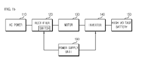
- FIG.1b is a schematic block diagram illustrating a configuration of FIG.1a .
- the low voltage rectifier (170) and the controller (180) illustrated in the lower part of FIG.1b will be omitted in explanation for brevity of explanation and easy understanding.
- a power supply unit (190) is mounted on the rectifier (120) and the inverter (140) for supplying a power to controllably drive a switching unit mounted inside the rectifier (120) and the inverter (140).
- the power supply unit (190) may provide a power for driving the rectifier (120) and the switching unit of the inverter (140).
- the power supply unit (190) in FIG.1b is a common element for the rectifier (120) and the inverter (140), such that in a case the power supply unit (190) fails to operate normally, that is, if the power supply unit (190) is inoperative, there is a problem in which the inverter-charger combined device (100) cannot be operated normally. A measure to solve the problem will be described later.
- FIG.2a is a block diagram illustrating an inverter-charger combined device for electric vehicles according to an exemplary embodiment of the present disclosure.
- the inverter-charger combined device (100) for electric vehicles may include two power supply units, that is, a first power supply unit (191) and a second power supply unit (192).
- the first power supply unit (191) is to provide a driving power of a switching unit of the rectifier (120), and the second power supply unit (192) is to provide a driving power of a switching unit of the inverter (140).
- the first power supply unit (191) and the second power supply unit (192) may operate independently and may independently provide a power to the switching unit of the rectifier (120) and the switching unit of the inverter (140). That is, even if any one of the first power supply unit (191) and the second power supply unit (192) develops a failure, the remaining other power supply unit is not affected at all.
- a switching unit may be interposed between the first power supply unit (191) and the switching unit of the rectifier (120) or between the second power supply unit (192) and the switching unit of the inverter (140).
- the switching unit for selecting the power supply unit may select the first power supply unit (191) or the second power supply unit (192) in response to operation state of the first power supply unit (191) or the second power supply unit (192), or may be connected to the switching unit of the rectifier (120) or the switching unit of the inverter (140).
- the operational control of the switching unit may be implemented by the abovementioned controller (180), or may be implemented by separate control means (not shown) inside the first power supply unit (191) or the second power supply unit (192) for operational control of the switching unit.
- the operation of the switching unit will be described in detail in the later explanation.
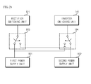
- FIG.2b is a block diagram illustrating a configuration of a power supply unit in an inverter-charger combined device for electric vehicles according to an exemplary embodiment of the present disclosure.
- the inverter-charger combined device for electric vehicles may include two power supply units, that is, the first power supply unit (191) and the second power supply unit (192). Furthermore, these power supply units are respectively connected to a switching unit (121) of the rectifier and to a switching unit (141) of the inverter for supply of power thereto.
- the connection relationship and power supply for driving means a connection relationship and power supply at the default state, and these connection relationships and power supply may be different from a case where the power supply units (191, 192) are defaulted.
- the inverter-charger combined device for electric vehicles is configured in such a manner that a driving power is supplied to the switching unit (121) of the rectifier (120) and to the switching unit (141) of the inverter (140) via mutually different power supply units.
- the first power supply unit (191) may supply a driving power to the switching unit (121) of the rectifier (120) and the second power supply unit (192) may supply a driving power to the switching unit (141) of the inverter (140).
- the combined device (100) in FIG.1 cannot perform a charging operation (or a charging mode) of the high voltage battery (150), and only the driving (or driving mode) of the motor (130) can be performed via a power charged in the high voltage battery (150).
- the controller (180) determines that the combined device must be operated under a charging mode, the combined device comes to be in an inoperative state.
- the second power supply unit (192) is not operating normally to disable to supply an appropriate power to the switching unit (141, S1 to S6) of the inverter (140), the combined device (100) cannot perform the charging operation of the high voltage battery (150) and cannot drive the motor (130) via the power charged in the high voltage battery (150), because the inverter (140) is not operating normally.
- the inverter-charger combined device for electric vehicles may use a first switching unit (193) and a second switching unit (194).
- first switching unit (193) and the second switching unit (194) are mounted separately from the first power supply unit (191) and the second power supply unit (192), the first switching unit (193) and the second switching unit (194) may be embedded in the first power supply unit (191) and the second power supply unit (192).
- the first power supply unit (191) fails to operate normally, a driving power cannot be supplied to the switching unit (121) of the rectifier normally, such that the first switching unit (193) may select the second power supply unit (192).
- the second power supply unit (192) fails to operate normally, a driving power cannot be supplied to the switching unit (141) of the inverter normally, such that the second switching unit (194) may select the first power supply unit (191).
- control of the switching operation of the first switching unit (193) and the second switching unit (194) may be performed by control means embedded inside the first and second power supply units (191, 192) or by the controller (180).
- inverter-charger combined device for electric vehicles and the control method thereof may, however, be embodied in many different forms and should not be construed as limited to the embodiment set forth herein.
- embodiment of the present disclosure may cover the modifications and variations of this disclosure provided they come within the scope of the appended claims and their equivalents. While particular features or aspects may have been disclosed with respect to several embodiments, such features or aspects may be selectively combined with one or more other features and/or aspects of other embodiments as may be desired.
Landscapes
- Engineering & Computer Science (AREA)
- Power Engineering (AREA)
- Transportation (AREA)
- Mechanical Engineering (AREA)
- Life Sciences & Earth Sciences (AREA)
- Sustainable Development (AREA)
- Sustainable Energy (AREA)
- Charge And Discharge Circuits For Batteries Or The Like (AREA)
- Electric Propulsion And Braking For Vehicles (AREA)
Abstract
Description
- The present disclosure relates to an inverter-charger combined device for electric vehicles and a control method thereof.
- Generally, an electric vehicle includes a high voltage battery charged with a high voltage, e.g., approximately 72 volts, a 3-phase motor driven by a power charged in the high voltage battery to run an electric vehicle, and an inverter for driving the 3-phase motor. However, the driving of the 3-phase motor using the power charged in the high voltage batter is limited by capacity of the high voltage battery.
- That is, in a case the power remaining in the high voltage battery of the electric vehicle drops below a predetermined level, the 3-phase motor cannot be driven any longer. Hence, the electric vehicle is equipped with a high voltage charger to charge the high voltage battery. The high voltage charger may be largely classified to two types, i.e., a slow speed charger using a household single AC power, and a high speed charger using a transmission and distribution 3-phase AC power.
- Meanwhile, each of the inverter, the high voltage charger and the low voltage charger is separately installed, such that it takes lots of time and man power to respectively install the inverter, the high voltage charger and the low voltage charger on the electric vehicle. Thus, an inverter-charger combined device for electric vehicle is being developed that is combined of the inverter, the high voltage charger and the low voltage charger in one integrated configuration.
- However, a power unit applied to a switching element of the inverter-charger combined device is configured in a common power source, and there is no sufficient measure to cope with a situation where the power unit is out of order.
- Exemplary aspects of the present disclosure are to substantially solve at least the above problems and/or disadvantages and to provide at least the advantages as mentioned below. Thus, the present disclosure is directed to provide an inverter-charger combined device for electric vehicles configured to individually mount a power unit applied to a switching element of the inverter-charger combined device to enable a stable operation even during partial failure of the power unit, and a control method thereof.
- Technical problems to be solved by the present disclosure are not restricted to the above-mentioned descriptions, and any other technical problems not mentioned so far will be clearly appreciated from the following description by skilled in the art.
- In one general aspect of the present invention, there is provided an inverter-charger combined device for electric vehicles configured to drive a 3-phase motor by charging a high voltage battery in case of charging mode, and switching a power of the high voltage battery in case of operation mode, the device comprising:
- a rectifier providing a power for charging the high voltage by rectifying an inputted AC power;
- an inverter receiving the AC power rectified by the rectifier via the 3-phase motor in case of charging mode to rectify the AC power to a DC power in case of charging mode, and converting the DC power charged in the high voltage battery in case of operation mode to driving the 3-phase motor; and
- a power supply unit supplying a power to drive the rectifier and the inverter.
- Preferably, but not necessarily, the device may further comprise: a low voltage rectifier for supplying a low voltage DC power to a load including a controller; and a controller configured to control the rectifier, the inverter and the low voltage rectifier.
- Preferably, but not necessarily, the power supply unit may include a first power supply unit for supplying a power for driving a switching unit of the rectifier, and a second power supply unit for supplying a power for driving a switching unit of the inverter.
- Preferably, but not necessarily, each of the first and second power supply units may be configured to independently supply a power.
- Preferably, but not necessarily, the device may further comprise: a first switching unit for selecting the first power supply unit or the second power supply unit to supply a power to drive the switching unit of the rectifier; and
a second switching unit for selecting the first power supply unit or the second power supply unit to supply a power to drive the switching unit of the inverter. - Preferably, but not necessarily, the first switching unit may be embedded in the first power supply unit, and the second switching unit may be embedded in the second power supply unit.
- Preferably, but not necessarily, the first switching unit and the second switching unit may be configured to select the first power supply unit or the second power supply unit in response to an operation state of the first power supply unit or the second power supply unit.
- Preferably, but not necessarily, the first switching unit and the second switching unit may be configured to supply a power to the switching unit of the rectifier and the switching unit of the inverter from the second power supply unit by selecting the second power supply unit in case of failure at the first power supply unit, and to supply a power to the switching unit of the rectifier and the switching unit of the inverter from the first power supply unit by selecting the first power supply unit in case of failure at the second power supply unit.
- In another general aspect of the present invention, there is provided a control method for an inverter-charger combined device for electric vehicles configured to drive a 3-phase motor by charging a high voltage battery in case of charging mode, and switching a power of the high voltage battery in case of operation mode, the method comprising:
- selecting a switch of a rectifier rectifying an AC power inputted for providing a power for charging the high voltage battery in case of charging mode;
- supplying a driving power to the switch of the rectifier for rectifying the inputted AC power;
- supplying the AC power rectified by the rectifier to the 3-phase motor; and
- receiving the rectified AC power from the 3-phase motor for rectification to a DC power, and charging the high voltage battery.
- In still another general aspect of the present invention, there is provided a control method for an inverter-charger combined device for electric vehicles configured to drive a 3-phase motor by charging a high voltage battery in case of charging mode, and switching a power of the high voltage battery in case of operation mode, the method comprising:
- selecting a switch of an inverter supplying a power to drive the 3-phase motor from the charged high voltage battery in case of operation mode;
- supplying a DC power charged in the high voltage battery to the switch of the inverter; and
- driving the 3-phase motor by converting the DC power to a 3-phase AC power.
- In an advantageous effect, the inverter-charger combined device for electric vehicles can be normally operated using other remaining power supply units even if one power supply unit fails, by separately configuring a power supply unit of a rectifier and a power supply unit of an inverter, in a case all functions are inoperative if a common power supply unit to the rectifier and the inverter is used and becomes inoperative.
- The teachings of the present disclosure can be readily understood by considering the following detailed description in conjunction with the accompanying drawings, in which:
-
FIG.1a is a block diagram illustrating a configuration of an inverter-charger combined device for electric vehicles according to an exemplary embodiment of the present disclosure; -
FIG.1b is a block diagram illustrating a configuration ofFIG.1a ; -
FIG.2a is a block diagram illustrating an inverter-charger combined device for electric vehicles according to an exemplary embodiment of the present disclosure; and -
FIG.2b is a block diagram illustrating a configuration of a power supply unit in an inverter-charger combined device for electric vehicles according to an exemplary embodiment of the present disclosure. - Various exemplary embodiments will be described more fully hereinafter with reference to the accompanying drawings, in which some exemplary embodiments are shown. The present inventive concept may, however, be embodied in many different forms and should not be construed as limited to the example embodiments set forth herein. Rather, the described aspect is intended to embrace all such alterations, modifications, and variations that fall within the scope and novel idea of the present disclosure.
- Now, exemplary embodiments of the present disclosure will be explained in detail together with the figures.
- The inverter-charger combined device (100) for electric vehicles according to an exemplary embodiment of the present disclosure may include a rectifier rectifying an AC power, a low voltage rectifier (170) for supplying a low voltage DC power to a load including a controller, a motor (130) for driving an electric vehicle, an inverter (140) driving the motor and supplying a charged power to a high voltage battery (160), a controller (180) for controlling the rectifier, the low voltage rectifier and the inverter.
- The rectifier (120) may provide a power for charging the high voltage battery (160) by rectifying a single AC power (110).
- The low voltage rectifier (170) for supplying a low voltage DC power may receive a DC power (LDC+, LDC-) rectified by the inverter (140), perform a voltage drop and provide the voltage-dropped power to a device or an element requiring a low voltage (e.g., 12V) DC power inside the device (100).
- Furthermore, the low voltage rectifier (170) may charge a low voltage battery (151) via a transformer. The low voltage rectifier (170) may be analogous to that mounted on a conventional vehicle.
- The motor (130) is provided to drive an electric vehicle and may function to transmit an AC power rectified by a single phase rectifier to an inverter side during a charging mode. Furthermore, the motor (130) may be driven by being supplied with an AC power generated by switching, by an inverter, a power charged in a battery during an operation mode.
- The inverter (140) may function to rectify a DC power by receiving an AC power rectified by a single phase rectifier from a 3-phase motor to a DC power. The inverter (140) may function to drive a 3-phase motor by converting a DC power charged in a battery to a 3-phase AC power during an operation mode.
- The controller (180) may function to perform an overall control of elements included in the device (100). The controller (180) may control a switching element configured to disconnect a connection between the rectifier (120) and the motor (130) during an operation mode. For example, the switching element may be a switching unit (SW) inside the rectifier (120).
- The controller (180) may control operations of the rectifier (120), the low voltage rectifier (170) and the inverter (140). Furthermore, the controller (180) may control an additional function of an electric vehicle (EV).
- Meanwhile, in a case the inverter-charger combined device (100) for electric vehicles is operated under an operation mode or a charging mode, a driving power must be supplied to each switching unit (S1 to S6) of the inverter (140) and the switching unit (SW) of the rectifier (120), details of which will be described with reference to
FIG.1a . -
FIG.1b is a schematic block diagram illustrating a configuration ofFIG.1a . The low voltage rectifier (170) and the controller (180) illustrated in the lower part ofFIG.1b will be omitted in explanation for brevity of explanation and easy understanding. - Referring to
FIG.1b , a power supply unit (190) is mounted on the rectifier (120) and the inverter (140) for supplying a power to controllably drive a switching unit mounted inside the rectifier (120) and the inverter (140). The power supply unit (190) may provide a power for driving the rectifier (120) and the switching unit of the inverter (140). However, as described in the foregoing, the power supply unit (190) inFIG.1b is a common element for the rectifier (120) and the inverter (140), such that in a case the power supply unit (190) fails to operate normally, that is, if the power supply unit (190) is inoperative, there is a problem in which the inverter-charger combined device (100) cannot be operated normally. A measure to solve the problem will be described later. -
FIG.2a is a block diagram illustrating an inverter-charger combined device for electric vehicles according to an exemplary embodiment of the present disclosure. - Referring to
FIG2a , the inverter-charger combined device (100) for electric vehicles according to an exemplary embodiment of the present disclosure may include two power supply units, that is, a first power supply unit (191) and a second power supply unit (192). - The first power supply unit (191) is to provide a driving power of a switching unit of the rectifier (120), and the second power supply unit (192) is to provide a driving power of a switching unit of the inverter (140).
- The first power supply unit (191) and the second power supply unit (192) may operate independently and may independently provide a power to the switching unit of the rectifier (120) and the switching unit of the inverter (140). That is, even if any one of the first power supply unit (191) and the second power supply unit (192) develops a failure, the remaining other power supply unit is not affected at all.
- Furthermore, a switching unit may be interposed between the first power supply unit (191) and the switching unit of the rectifier (120) or between the second power supply unit (192) and the switching unit of the inverter (140). The switching unit for selecting the power supply unit may select the first power supply unit (191) or the second power supply unit (192) in response to operation state of the first power supply unit (191) or the second power supply unit (192), or may be connected to the switching unit of the rectifier (120) or the switching unit of the inverter (140).
- The operational control of the switching unit may be implemented by the abovementioned controller (180), or may be implemented by separate control means (not shown) inside the first power supply unit (191) or the second power supply unit (192) for operational control of the switching unit. The operation of the switching unit will be described in detail in the later explanation.
-
FIG.2b is a block diagram illustrating a configuration of a power supply unit in an inverter-charger combined device for electric vehicles according to an exemplary embodiment of the present disclosure. - Referring to
FIG.2a , the inverter-charger combined device for electric vehicles according to an exemplary embodiment of the present disclosure may include two power supply units, that is, the first power supply unit (191) and the second power supply unit (192). Furthermore, these power supply units are respectively connected to a switching unit (121) of the rectifier and to a switching unit (141) of the inverter for supply of power thereto. Of course, the connection relationship and power supply for driving means a connection relationship and power supply at the default state, and these connection relationships and power supply may be different from a case where the power supply units (191, 192) are defaulted. - Basically, the inverter-charger combined device for electric vehicles according to an exemplary embodiment of the present disclosure is configured in such a manner that a driving power is supplied to the switching unit (121) of the rectifier (120) and to the switching unit (141) of the inverter (140) via mutually different power supply units. In other words, as explained before, during the default state, the first power supply unit (191) may supply a driving power to the switching unit (121) of the rectifier (120) and the second power supply unit (192) may supply a driving power to the switching unit (141) of the inverter (140).
- However, in a case the first power supply unit (191) is not operating normally to disable to supply an appropriate power to the switching unit (121, SW) of the rectifier (120), the combined device (100) in
FIG.1 cannot perform a charging operation (or a charging mode) of the high voltage battery (150), and only the driving (or driving mode) of the motor (130) can be performed via a power charged in the high voltage battery (150). Thus, under this circumstance, in a case a user or the controller (180) determines that the combined device must be operated under a charging mode, the combined device comes to be in an inoperative state. - Furthermore, in a case the second power supply unit (192) is not operating normally to disable to supply an appropriate power to the switching unit (141, S1 to S6) of the inverter (140), the combined device (100) cannot perform the charging operation of the high voltage battery (150) and cannot drive the motor (130) via the power charged in the high voltage battery (150), because the inverter (140) is not operating normally.
- In order to solve the problems thus explained, the inverter-charger combined device for electric vehicles according to an exemplary embodiment of the present disclosure may use a first switching unit (193) and a second switching unit (194).
- Referring to
FIG.2b , although it is depicted that the first switching unit (193) and the second switching unit (194) are mounted separately from the first power supply unit (191) and the second power supply unit (192), the first switching unit (193) and the second switching unit (194) may be embedded in the first power supply unit (191) and the second power supply unit (192). - In a case the first power supply unit (191) fails to operate normally, a driving power cannot be supplied to the switching unit (121) of the rectifier normally, such that the first switching unit (193) may select the second power supply unit (192). Furthermore, in a case the second power supply unit (192) fails to operate normally, a driving power cannot be supplied to the switching unit (141) of the inverter normally, such that the second switching unit (194) may select the first power supply unit (191).
- As apparent from the foregoing, the control of the switching operation of the first switching unit (193) and the second switching unit (194) may be performed by control means embedded inside the first and second power supply units (191, 192) or by the controller (180).
- The above-mentioned inverter-charger combined device for electric vehicles and the control method thereof according to the exemplary embodiments of the present disclosure may, however, be embodied in many different forms and should not be construed as limited to the embodiment set forth herein. Thus, it is intended that embodiment of the present disclosure may cover the modifications and variations of this disclosure provided they come within the scope of the appended claims and their equivalents. While particular features or aspects may have been disclosed with respect to several embodiments, such features or aspects may be selectively combined with one or more other features and/or aspects of other embodiments as may be desired.
Claims (10)
- An inverter-charger combined device (100) configured to charge a high voltage battery in case of charging mode, and drive a 3-phase motor by switching a power of the high voltage battery in case of operation mode, the device characterized by:a rectifier (120) providing a power for charging the high voltage by rectifying an inputted AC power;an inverter (140) receiving the AC power rectified by the rectifier (120) via the 3-phase motor in case of charging mode to rectify the AC power to a DC power,and converting the DC power charged in the high voltage battery in case of operation mode to drive the 3-phase motor; anda power supply unit (190) supplying a power to drive the rectifier and the inverter.
- The device of claim 1, further characterized by: a low voltage rectifier (170) for supplying a low voltage DC power to a load including a controller; and a controller (180) configured to control the rectifier (120), the inverter (140) and the low voltage rectifier (170).
- The device of claim 1 or 2, characterized in that the power supply unit (190) includes a first power supply unit (191) for supplying a power to drive a switching unit (121) of the rectifier, and a second power supply unit (192) for supplying a power to drive a switching unit (141) of the inverter (140).
- The device of claim 3, characterized in that each of the first and second power supply units (191, 192) is configured to independently supply a power.
- The device of claim 3, further characterized by: a first switching unit (193) for selecting the first power supply unit or the second power supply unit to supply a power to drive the switching unit of the rectifier; and
a second switching unit (194) for selecting the first power supply unit or the second power supply unit to supply a power to drive the switching unit of the inverter. - The device of claim 5, characterized in that the first switching unit is embedded in the first power supply unit, and the second switching unit is embedded in the second power supply unit.
- The device of claim 5, characterized in that the first switching unit and the second switching unit are configured to select the first power supply unit or the second power supply unit in response to an operation state of the first power supply unit or the second power supply unit.
- The device of claim 5, characterized in that the first switching unit and the second switching unit are configured to supply a power to the switching unit of the rectifier and the switching unit of the inverter from the second power supply unit by selecting the second power supply unit in case of failure at the first power supply unit, and to supply a power to the switching unit of the rectifier and the switching unit of the inverter from the first power supply unit by selecting the first power supply unit in case of failure at the second power supply unit.
- A control method for an inverter-charger combined device (100) configured to charge a high voltage battery in case of charging mode, and drive a 3-phase motor by switching a power of the high voltage battery in case of operation mode, the method characterized by:selecting a switch of a rectifier rectifying an AC power inputted for providing a power for charging the high voltage battery in case of charging mode;supplying a driving power to the switch of the rectifier for rectifying the inputted AC power;supplying the AC power rectified by the rectifier to the 3-phase motor; andreceiving the rectified AC power from the 3-phase motor for rectification to a DC power, and charging the high voltage battery.
- A control method for an inverter-charger combined device (100) configured to charge a high voltage battery in case of charging mode, and drive a 3-phase motor by switching a power of the high voltage battery in case of operation mode, the method characterized by:selecting a switch of an inverter supplying a power to drive the 3-phase motor from the charged high voltage battery in case of operation mode;supplying a DC power charged in the high voltage battery to the switch of the inverter; anddriving the 3-phase motor by converting the DC power to a 3-phase AC power.
Applications Claiming Priority (1)
| Application Number | Priority Date | Filing Date | Title |
|---|---|---|---|
| KR1020120053559A KR101369052B1 (en) | 2012-05-21 | 2012-05-21 | Inverter-charger combined device for electric vehicles |
Publications (3)
| Publication Number | Publication Date |
|---|---|
| EP2677626A1 true EP2677626A1 (en) | 2013-12-25 |
| EP2677626B1 EP2677626B1 (en) | 2016-07-13 |
| EP2677626B9 EP2677626B9 (en) | 2016-10-19 |
Family
ID=48366278
Family Applications (1)
| Application Number | Title | Priority Date | Filing Date |
|---|---|---|---|
| EP13168054.8A Not-in-force EP2677626B9 (en) | 2012-05-21 | 2013-05-16 | Inverter-charger combined device for electric vehicles and method thereof |
Country Status (6)
| Country | Link |
|---|---|
| US (1) | US9496804B2 (en) |
| EP (1) | EP2677626B9 (en) |
| JP (1) | JP5675893B2 (en) |
| KR (1) | KR101369052B1 (en) |
| CN (1) | CN103427456B (en) |
| ES (1) | ES2590502T3 (en) |
Families Citing this family (14)
| Publication number | Priority date | Publication date | Assignee | Title |
|---|---|---|---|---|
| CN104092273B (en) * | 2014-07-25 | 2017-01-18 | 中山大洋电机股份有限公司 | Electric vehicle driving and charging integrated control method and electric vehicle operated with same |
| CN104608649B (en) * | 2015-02-06 | 2017-03-15 | 山东大学 | Integrated electric energy of electric automobile transformation system |
| CN104670040B (en) * | 2015-02-11 | 2016-11-23 | 南京航空航天大学 | A kind of charging electric vehicle and driving integrated topological |
| CN106143175B (en) * | 2015-04-24 | 2018-09-07 | 乐金电子研发中心(上海)有限公司 | A kind of charging of electric vehicle and motor driving integrated circuit |
| DE102016200682A1 (en) | 2016-01-20 | 2017-07-20 | Robert Bosch Gmbh | Electrically powered means of locomotion, electric drive train and arrangement for charging, inverting and returning |
| KR102461367B1 (en) * | 2016-10-05 | 2022-10-31 | 볼투 모터 인코퍼레이티드 | electric vehicle |
| CN107244255B (en) * | 2017-06-26 | 2024-01-05 | 江苏师范大学 | H-bridge and high-frequency transformer-based electric automobile charging and driving integrated converter |
| DE102017115506B4 (en) * | 2017-07-11 | 2023-12-28 | Dr. Ing. H.C. F. Porsche Aktiengesellschaft | Control device for an inverter |
| KR102654841B1 (en) * | 2018-12-07 | 2024-04-05 | 현대자동차주식회사 | united converter apparatus and method for operating thereof |
| KR102111092B1 (en) | 2019-07-31 | 2020-05-15 | 주식회사 이지트로닉스 | Inverter-charger combined device and controlling method thereof |
| KR20220029935A (en) | 2020-09-02 | 2022-03-10 | 주식회사 이지트로닉스 | Classification control method of charging mode and inverter mode of integrated smart inverter |
| EP4232313A1 (en) | 2020-11-24 | 2023-08-30 | Huawei Technologies Co., Ltd. | Arrangement for electric power conversion and electric drive |
| WO2024092180A1 (en) | 2022-10-27 | 2024-05-02 | Vitesco Technologies USA, LLC | Vehicle high voltage electronics box |
| WO2024233749A1 (en) | 2023-05-09 | 2024-11-14 | Vitesco Technologies USA, LLC | Vehicle high voltage electronics box with an open-end winding machine |
Citations (5)
| Publication number | Priority date | Publication date | Assignee | Title |
|---|---|---|---|---|
| US20060145542A1 (en) * | 2004-01-29 | 2006-07-06 | Chiyo Kusubayashi | Auxiliary power supply for vehicle |
| US20090230774A1 (en) * | 2008-03-17 | 2009-09-17 | Robert Bosch Gmbh | Extended controller keep alive system and method |
| EP2113410A1 (en) * | 2007-02-20 | 2009-11-04 | Toyota Jidosha Kabushiki Kaisha | Electric vehicle, vehicle charge device, and vehicle charge system |
| US20110169449A1 (en) * | 2008-10-22 | 2011-07-14 | Robert Dean King | Apparatus for transferring energy using power electronics and machine inductance and method of manufacturing same |
| WO2011128750A2 (en) * | 2010-04-14 | 2011-10-20 | Toyota Jidosha Kabushiki Kaisha | Power supply system and vehicle equipped with power supply system |
Family Cites Families (11)
| Publication number | Priority date | Publication date | Assignee | Title |
|---|---|---|---|---|
| JP3632776B2 (en) | 1994-10-03 | 2005-03-23 | 本田技研工業株式会社 | Electric vehicle charging device |
| JP3477850B2 (en) | 1994-10-26 | 2003-12-10 | 株式会社明電舎 | Electric vehicle charger |
| JPH09233708A (en) | 1996-02-27 | 1997-09-05 | Hino Motors Ltd | Battery charge alarm circuit |
| JP3703059B2 (en) * | 1997-10-14 | 2005-10-05 | 株式会社デンソー | Electric vehicle charger |
| JP3687409B2 (en) | 1999-04-26 | 2005-08-24 | トヨタ自動車株式会社 | Vehicle power supply control device |
| US6877578B2 (en) * | 2002-09-12 | 2005-04-12 | Visteon Global Technologies, Inc. | Multi-axle vehicle drive system |
| KR100715068B1 (en) * | 2005-08-25 | 2007-05-07 | 주식회사 엘지데이콤 | Power converter using multiple power sources |
| US8937455B2 (en) * | 2007-09-10 | 2015-01-20 | Toyota Jidosha Kabushiki Kaisha | Charging apparatus for vehicle and method for charging vehicle |
| KR20080037014A (en) * | 2008-02-11 | 2008-04-29 | 미쓰비시덴키 가부시키가이샤 | Control device of electric vehicle |
| JP5644070B2 (en) | 2008-07-16 | 2014-12-24 | 株式会社豊田中央研究所 | Power control device |
| JP2011072081A (en) | 2009-09-24 | 2011-04-07 | Fujitsu Ten Ltd | Control unit and control method of plug-in vehicle |
-
2012
- 2012-05-21 KR KR1020120053559A patent/KR101369052B1/en not_active Expired - Fee Related
-
2013
- 2013-05-14 US US13/894,152 patent/US9496804B2/en not_active Expired - Fee Related
- 2013-05-16 EP EP13168054.8A patent/EP2677626B9/en not_active Not-in-force
- 2013-05-16 ES ES13168054.8T patent/ES2590502T3/en active Active
- 2013-05-21 CN CN201310274454.3A patent/CN103427456B/en not_active Expired - Fee Related
- 2013-05-21 JP JP2013107161A patent/JP5675893B2/en not_active Expired - Fee Related
Patent Citations (5)
| Publication number | Priority date | Publication date | Assignee | Title |
|---|---|---|---|---|
| US20060145542A1 (en) * | 2004-01-29 | 2006-07-06 | Chiyo Kusubayashi | Auxiliary power supply for vehicle |
| EP2113410A1 (en) * | 2007-02-20 | 2009-11-04 | Toyota Jidosha Kabushiki Kaisha | Electric vehicle, vehicle charge device, and vehicle charge system |
| US20090230774A1 (en) * | 2008-03-17 | 2009-09-17 | Robert Bosch Gmbh | Extended controller keep alive system and method |
| US20110169449A1 (en) * | 2008-10-22 | 2011-07-14 | Robert Dean King | Apparatus for transferring energy using power electronics and machine inductance and method of manufacturing same |
| WO2011128750A2 (en) * | 2010-04-14 | 2011-10-20 | Toyota Jidosha Kabushiki Kaisha | Power supply system and vehicle equipped with power supply system |
Also Published As
| Publication number | Publication date |
|---|---|
| EP2677626B1 (en) | 2016-07-13 |
| JP5675893B2 (en) | 2015-02-25 |
| KR20130129568A (en) | 2013-11-29 |
| ES2590502T3 (en) | 2016-11-22 |
| US9496804B2 (en) | 2016-11-15 |
| US20130307333A1 (en) | 2013-11-21 |
| KR101369052B1 (en) | 2014-03-04 |
| EP2677626B9 (en) | 2016-10-19 |
| CN103427456A (en) | 2013-12-04 |
| JP2013243920A (en) | 2013-12-05 |
| CN103427456B (en) | 2015-08-19 |
Similar Documents
| Publication | Publication Date | Title |
|---|---|---|
| US9496804B2 (en) | Inverter-charger combined device for electric vehicles and method thereof | |
| KR101273736B1 (en) | Inverter-charger conversed device for electric vehicles and method for controlling thereof | |
| US9371005B2 (en) | Battery management apparatus for an electric vehicle, and method for managing same | |
| US9172252B2 (en) | Power supply apparatus for electrically powered vehicle and method for controlling the same | |
| US7550861B2 (en) | AC power supplying system, power supply apparatus, and vehicle having the same | |
| EP2946975B1 (en) | Power management and environmental control system for vehicles | |
| US20050151517A1 (en) | Power management system for vehicles | |
| JP2012075241A (en) | Controller for electric vehicles | |
| CN102271958A (en) | Method for controlling a power supply device having a power inverter | |
| CN103419669A (en) | Method and apparatus for charging multiple energy storage devices | |
| US9637007B2 (en) | Supplying electric traction motors of a rail vehicle with electrical energy using a plurality of internal combustion engines | |
| JP2012075242A (en) | Controller for electric vehicles | |
| KR20200048913A (en) | Stand-alone household energy storage system based on waste battery | |
| JP2014110666A (en) | Discharge control system, and discharge device | |
| JP5704747B2 (en) | Charge control unit | |
| JP2018182829A (en) | Power converter | |
| US9493128B2 (en) | Method for operating an on-board power supply system of a motor vehicle | |
| JP5623558B2 (en) | Elevator control device | |
| KR101866001B1 (en) | Method and system for controlling low voltage dc/dc comverter for hybrid electric vehicle | |
| KR101303157B1 (en) | Electric vehicle and operating method the same | |
| JP5183709B2 (en) | Vehicle power supply | |
| KR102637683B1 (en) | Power generation and distribution | |
| JP2023123173A (en) | Power supply device | |
| HK1211276A1 (en) | Elevator | |
| HK1211276B (en) | Elevator |
Legal Events
| Date | Code | Title | Description |
|---|---|---|---|
| PUAI | Public reference made under article 153(3) epc to a published international application that has entered the european phase |
Free format text: ORIGINAL CODE: 0009012 |
|
| AK | Designated contracting states |
Kind code of ref document: A1 Designated state(s): AL AT BE BG CH CY CZ DE DK EE ES FI FR GB GR HR HU IE IS IT LI LT LU LV MC MK MT NL NO PL PT RO RS SE SI SK SM TR |
|
| AX | Request for extension of the european patent |
Extension state: BA ME |
|
| 17P | Request for examination filed |
Effective date: 20140327 |
|
| RBV | Designated contracting states (corrected) |
Designated state(s): AL AT BE BG CH CY CZ DE DK EE ES FI FR GB GR HR HU IE IS IT LI LT LU LV MC MK MT NL NO PL PT RO RS SE SI SK SM TR |
|
| 17Q | First examination report despatched |
Effective date: 20150616 |
|
| GRAP | Despatch of communication of intention to grant a patent |
Free format text: ORIGINAL CODE: EPIDOSNIGR1 |
|
| INTG | Intention to grant announced |
Effective date: 20160224 |
|
| GRAS | Grant fee paid |
Free format text: ORIGINAL CODE: EPIDOSNIGR3 |
|
| GRAA | (expected) grant |
Free format text: ORIGINAL CODE: 0009210 |
|
| AK | Designated contracting states |
Kind code of ref document: B1 Designated state(s): AL AT BE BG CH CY CZ DE DK EE ES FI FR GB GR HR HU IE IS IT LI LT LU LV MC MK MT NL NO PL PT RO RS SE SI SK SM TR |
|
| REG | Reference to a national code |
Ref country code: GB Ref legal event code: FG4D |
|
| REG | Reference to a national code |
Ref country code: AT Ref legal event code: REF Ref document number: 812995 Country of ref document: AT Kind code of ref document: T Effective date: 20160715 Ref country code: CH Ref legal event code: EP |
|
| REG | Reference to a national code |
Ref country code: IE Ref legal event code: FG4D |
|
| REG | Reference to a national code |
Ref country code: DE Ref legal event code: R096 Ref document number: 602013009278 Country of ref document: DE |
|
| REG | Reference to a national code |
Ref country code: LT Ref legal event code: MG4D |
|
| REG | Reference to a national code |
Ref country code: NL Ref legal event code: MP Effective date: 20160713 |
|
| REG | Reference to a national code |
Ref country code: ES Ref legal event code: FG2A Ref document number: 2590502 Country of ref document: ES Kind code of ref document: T3 Effective date: 20161122 |
|
| REG | Reference to a national code |
Ref country code: AT Ref legal event code: MK05 Ref document number: 812995 Country of ref document: AT Kind code of ref document: T Effective date: 20160713 |
|
| PG25 | Lapsed in a contracting state [announced via postgrant information from national office to epo] |
Ref country code: NL Free format text: LAPSE BECAUSE OF FAILURE TO SUBMIT A TRANSLATION OF THE DESCRIPTION OR TO PAY THE FEE WITHIN THE PRESCRIBED TIME-LIMIT Effective date: 20160713 Ref country code: IS Free format text: LAPSE BECAUSE OF FAILURE TO SUBMIT A TRANSLATION OF THE DESCRIPTION OR TO PAY THE FEE WITHIN THE PRESCRIBED TIME-LIMIT Effective date: 20161113 Ref country code: NO Free format text: LAPSE BECAUSE OF FAILURE TO SUBMIT A TRANSLATION OF THE DESCRIPTION OR TO PAY THE FEE WITHIN THE PRESCRIBED TIME-LIMIT Effective date: 20161013 Ref country code: HR Free format text: LAPSE BECAUSE OF FAILURE TO SUBMIT A TRANSLATION OF THE DESCRIPTION OR TO PAY THE FEE WITHIN THE PRESCRIBED TIME-LIMIT Effective date: 20160713 Ref country code: LT Free format text: LAPSE BECAUSE OF FAILURE TO SUBMIT A TRANSLATION OF THE DESCRIPTION OR TO PAY THE FEE WITHIN THE PRESCRIBED TIME-LIMIT Effective date: 20160713 Ref country code: FI Free format text: LAPSE BECAUSE OF FAILURE TO SUBMIT A TRANSLATION OF THE DESCRIPTION OR TO PAY THE FEE WITHIN THE PRESCRIBED TIME-LIMIT Effective date: 20160713 Ref country code: RS Free format text: LAPSE BECAUSE OF FAILURE TO SUBMIT A TRANSLATION OF THE DESCRIPTION OR TO PAY THE FEE WITHIN THE PRESCRIBED TIME-LIMIT Effective date: 20160713 |
|
| PG25 | Lapsed in a contracting state [announced via postgrant information from national office to epo] |
Ref country code: GR Free format text: LAPSE BECAUSE OF FAILURE TO SUBMIT A TRANSLATION OF THE DESCRIPTION OR TO PAY THE FEE WITHIN THE PRESCRIBED TIME-LIMIT Effective date: 20161014 Ref country code: PT Free format text: LAPSE BECAUSE OF FAILURE TO SUBMIT A TRANSLATION OF THE DESCRIPTION OR TO PAY THE FEE WITHIN THE PRESCRIBED TIME-LIMIT Effective date: 20161114 Ref country code: LV Free format text: LAPSE BECAUSE OF FAILURE TO SUBMIT A TRANSLATION OF THE DESCRIPTION OR TO PAY THE FEE WITHIN THE PRESCRIBED TIME-LIMIT Effective date: 20160713 Ref country code: AT Free format text: LAPSE BECAUSE OF FAILURE TO SUBMIT A TRANSLATION OF THE DESCRIPTION OR TO PAY THE FEE WITHIN THE PRESCRIBED TIME-LIMIT Effective date: 20160713 Ref country code: SE Free format text: LAPSE BECAUSE OF FAILURE TO SUBMIT A TRANSLATION OF THE DESCRIPTION OR TO PAY THE FEE WITHIN THE PRESCRIBED TIME-LIMIT Effective date: 20160713 Ref country code: PL Free format text: LAPSE BECAUSE OF FAILURE TO SUBMIT A TRANSLATION OF THE DESCRIPTION OR TO PAY THE FEE WITHIN THE PRESCRIBED TIME-LIMIT Effective date: 20160713 Ref country code: BE Free format text: LAPSE BECAUSE OF FAILURE TO SUBMIT A TRANSLATION OF THE DESCRIPTION OR TO PAY THE FEE WITHIN THE PRESCRIBED TIME-LIMIT Effective date: 20160713 |
|
| REG | Reference to a national code |
Ref country code: FR Ref legal event code: PLFP Year of fee payment: 5 |
|
| REG | Reference to a national code |
Ref country code: DE Ref legal event code: R097 Ref document number: 602013009278 Country of ref document: DE |
|
| PG25 | Lapsed in a contracting state [announced via postgrant information from national office to epo] |
Ref country code: RO Free format text: LAPSE BECAUSE OF FAILURE TO SUBMIT A TRANSLATION OF THE DESCRIPTION OR TO PAY THE FEE WITHIN THE PRESCRIBED TIME-LIMIT Effective date: 20160713 Ref country code: EE Free format text: LAPSE BECAUSE OF FAILURE TO SUBMIT A TRANSLATION OF THE DESCRIPTION OR TO PAY THE FEE WITHIN THE PRESCRIBED TIME-LIMIT Effective date: 20160713 |
|
| PLBE | No opposition filed within time limit |
Free format text: ORIGINAL CODE: 0009261 |
|
| STAA | Information on the status of an ep patent application or granted ep patent |
Free format text: STATUS: NO OPPOSITION FILED WITHIN TIME LIMIT |
|
| PG25 | Lapsed in a contracting state [announced via postgrant information from national office to epo] |
Ref country code: DK Free format text: LAPSE BECAUSE OF FAILURE TO SUBMIT A TRANSLATION OF THE DESCRIPTION OR TO PAY THE FEE WITHIN THE PRESCRIBED TIME-LIMIT Effective date: 20160713 Ref country code: SM Free format text: LAPSE BECAUSE OF FAILURE TO SUBMIT A TRANSLATION OF THE DESCRIPTION OR TO PAY THE FEE WITHIN THE PRESCRIBED TIME-LIMIT Effective date: 20160713 Ref country code: SK Free format text: LAPSE BECAUSE OF FAILURE TO SUBMIT A TRANSLATION OF THE DESCRIPTION OR TO PAY THE FEE WITHIN THE PRESCRIBED TIME-LIMIT Effective date: 20160713 Ref country code: BG Free format text: LAPSE BECAUSE OF FAILURE TO SUBMIT A TRANSLATION OF THE DESCRIPTION OR TO PAY THE FEE WITHIN THE PRESCRIBED TIME-LIMIT Effective date: 20161013 Ref country code: CZ Free format text: LAPSE BECAUSE OF FAILURE TO SUBMIT A TRANSLATION OF THE DESCRIPTION OR TO PAY THE FEE WITHIN THE PRESCRIBED TIME-LIMIT Effective date: 20160713 |
|
| 26N | No opposition filed |
Effective date: 20170418 |
|
| PG25 | Lapsed in a contracting state [announced via postgrant information from national office to epo] |
Ref country code: SI Free format text: LAPSE BECAUSE OF FAILURE TO SUBMIT A TRANSLATION OF THE DESCRIPTION OR TO PAY THE FEE WITHIN THE PRESCRIBED TIME-LIMIT Effective date: 20160713 Ref country code: LU Free format text: LAPSE BECAUSE OF NON-PAYMENT OF DUE FEES Effective date: 20170531 |
|
| REG | Reference to a national code |
Ref country code: CH Ref legal event code: PL |
|
| PG25 | Lapsed in a contracting state [announced via postgrant information from national office to epo] |
Ref country code: MC Free format text: LAPSE BECAUSE OF FAILURE TO SUBMIT A TRANSLATION OF THE DESCRIPTION OR TO PAY THE FEE WITHIN THE PRESCRIBED TIME-LIMIT Effective date: 20160713 |
|
| REG | Reference to a national code |
Ref country code: IE Ref legal event code: MM4A |
|
| PG25 | Lapsed in a contracting state [announced via postgrant information from national office to epo] |
Ref country code: LI Free format text: LAPSE BECAUSE OF NON-PAYMENT OF DUE FEES Effective date: 20170531 Ref country code: CH Free format text: LAPSE BECAUSE OF NON-PAYMENT OF DUE FEES Effective date: 20170531 |
|
| PG25 | Lapsed in a contracting state [announced via postgrant information from national office to epo] |
Ref country code: LU Free format text: LAPSE BECAUSE OF NON-PAYMENT OF DUE FEES Effective date: 20170516 |
|
| PG25 | Lapsed in a contracting state [announced via postgrant information from national office to epo] |
Ref country code: IE Free format text: LAPSE BECAUSE OF NON-PAYMENT OF DUE FEES Effective date: 20170516 |
|
| REG | Reference to a national code |
Ref country code: FR Ref legal event code: PLFP Year of fee payment: 6 |
|
| PG25 | Lapsed in a contracting state [announced via postgrant information from national office to epo] |
Ref country code: MT Free format text: LAPSE BECAUSE OF NON-PAYMENT OF DUE FEES Effective date: 20170516 |
|
| PG25 | Lapsed in a contracting state [announced via postgrant information from national office to epo] |
Ref country code: AL Free format text: LAPSE BECAUSE OF FAILURE TO SUBMIT A TRANSLATION OF THE DESCRIPTION OR TO PAY THE FEE WITHIN THE PRESCRIBED TIME-LIMIT Effective date: 20160713 |
|
| PGFP | Annual fee paid to national office [announced via postgrant information from national office to epo] |
Ref country code: DE Payment date: 20180705 Year of fee payment: 6 Ref country code: ES Payment date: 20180711 Year of fee payment: 6 Ref country code: IT Payment date: 20180817 Year of fee payment: 6 Ref country code: FR Payment date: 20180705 Year of fee payment: 6 |
|
| PGFP | Annual fee paid to national office [announced via postgrant information from national office to epo] |
Ref country code: GB Payment date: 20180706 Year of fee payment: 6 |
|
| PG25 | Lapsed in a contracting state [announced via postgrant information from national office to epo] |
Ref country code: HU Free format text: LAPSE BECAUSE OF FAILURE TO SUBMIT A TRANSLATION OF THE DESCRIPTION OR TO PAY THE FEE WITHIN THE PRESCRIBED TIME-LIMIT; INVALID AB INITIO Effective date: 20130516 |
|
| PG25 | Lapsed in a contracting state [announced via postgrant information from national office to epo] |
Ref country code: CY Free format text: LAPSE BECAUSE OF NON-PAYMENT OF DUE FEES Effective date: 20160713 |
|
| PG25 | Lapsed in a contracting state [announced via postgrant information from national office to epo] |
Ref country code: MK Free format text: LAPSE BECAUSE OF FAILURE TO SUBMIT A TRANSLATION OF THE DESCRIPTION OR TO PAY THE FEE WITHIN THE PRESCRIBED TIME-LIMIT Effective date: 20160713 |
|
| REG | Reference to a national code |
Ref country code: DE Ref legal event code: R119 Ref document number: 602013009278 Country of ref document: DE |
|
| GBPC | Gb: european patent ceased through non-payment of renewal fee |
Effective date: 20190516 |
|
| PG25 | Lapsed in a contracting state [announced via postgrant information from national office to epo] |
Ref country code: TR Free format text: LAPSE BECAUSE OF FAILURE TO SUBMIT A TRANSLATION OF THE DESCRIPTION OR TO PAY THE FEE WITHIN THE PRESCRIBED TIME-LIMIT Effective date: 20160713 |
|
| PG25 | Lapsed in a contracting state [announced via postgrant information from national office to epo] |
Ref country code: IT Free format text: LAPSE BECAUSE OF NON-PAYMENT OF DUE FEES Effective date: 20190516 Ref country code: DE Free format text: LAPSE BECAUSE OF NON-PAYMENT OF DUE FEES Effective date: 20191203 Ref country code: GB Free format text: LAPSE BECAUSE OF NON-PAYMENT OF DUE FEES Effective date: 20190516 |
|
| PG25 | Lapsed in a contracting state [announced via postgrant information from national office to epo] |
Ref country code: FR Free format text: LAPSE BECAUSE OF NON-PAYMENT OF DUE FEES Effective date: 20190531 |
|
| REG | Reference to a national code |
Ref country code: ES Ref legal event code: FD2A Effective date: 20200930 |
|
| PG25 | Lapsed in a contracting state [announced via postgrant information from national office to epo] |
Ref country code: ES Free format text: LAPSE BECAUSE OF NON-PAYMENT OF DUE FEES Effective date: 20190517 |