EP2677276A1 - Portable electronic device with gyro sensor, correction method for gyro sensor, and program - Google Patents
Portable electronic device with gyro sensor, correction method for gyro sensor, and program Download PDFInfo
- Publication number
- EP2677276A1 EP2677276A1 EP12747354.4A EP12747354A EP2677276A1 EP 2677276 A1 EP2677276 A1 EP 2677276A1 EP 12747354 A EP12747354 A EP 12747354A EP 2677276 A1 EP2677276 A1 EP 2677276A1
- Authority
- EP
- European Patent Office
- Prior art keywords
- housing
- angle
- gyro sensor
- electronic equipment
- change
- Prior art date
- Legal status (The legal status is an assumption and is not a legal conclusion. Google has not performed a legal analysis and makes no representation as to the accuracy of the status listed.)
- Withdrawn
Links
- 238000012937 correction Methods 0.000 title claims abstract description 54
- 238000000034 method Methods 0.000 title claims description 39
- 230000008859 change Effects 0.000 claims abstract description 95
- 238000001514 detection method Methods 0.000 claims description 94
- 230000008569 process Effects 0.000 claims description 6
- 238000004364 calculation method Methods 0.000 description 28
- 238000005259 measurement Methods 0.000 description 11
- 238000010586 diagram Methods 0.000 description 8
- 230000007704 transition Effects 0.000 description 7
- 230000007246 mechanism Effects 0.000 description 4
- 230000001186 cumulative effect Effects 0.000 description 2
- 238000013461 design Methods 0.000 description 2
- 230000004048 modification Effects 0.000 description 2
- 238000012986 modification Methods 0.000 description 2
- 230000001133 acceleration Effects 0.000 description 1
- 230000008901 benefit Effects 0.000 description 1
- 230000001413 cellular effect Effects 0.000 description 1
- 238000004590 computer program Methods 0.000 description 1
- 230000000694 effects Effects 0.000 description 1
- 238000007306 functionalization reaction Methods 0.000 description 1
- 230000036541 health Effects 0.000 description 1
- 238000007689 inspection Methods 0.000 description 1
- 230000003287 optical effect Effects 0.000 description 1
- 238000005070 sampling Methods 0.000 description 1
- 239000004065 semiconductor Substances 0.000 description 1
- 239000000758 substrate Substances 0.000 description 1
- 230000001052 transient effect Effects 0.000 description 1
Images


Classifications
-
- G—PHYSICS
- G01—MEASURING; TESTING
- G01C—MEASURING DISTANCES, LEVELS OR BEARINGS; SURVEYING; NAVIGATION; GYROSCOPIC INSTRUMENTS; PHOTOGRAMMETRY OR VIDEOGRAMMETRY
- G01C19/00—Gyroscopes; Turn-sensitive devices using vibrating masses; Turn-sensitive devices without moving masses; Measuring angular rate using gyroscopic effects
- G01C19/56—Turn-sensitive devices using vibrating masses, e.g. vibratory angular rate sensors based on Coriolis forces
- G01C19/5776—Signal processing not specific to any of the devices covered by groups G01C19/5607 - G01C19/5719
-
- G—PHYSICS
- G01—MEASURING; TESTING
- G01C—MEASURING DISTANCES, LEVELS OR BEARINGS; SURVEYING; NAVIGATION; GYROSCOPIC INSTRUMENTS; PHOTOGRAMMETRY OR VIDEOGRAMMETRY
- G01C19/00—Gyroscopes; Turn-sensitive devices using vibrating masses; Turn-sensitive devices without moving masses; Measuring angular rate using gyroscopic effects
-
- G—PHYSICS
- G01—MEASURING; TESTING
- G01C—MEASURING DISTANCES, LEVELS OR BEARINGS; SURVEYING; NAVIGATION; GYROSCOPIC INSTRUMENTS; PHOTOGRAMMETRY OR VIDEOGRAMMETRY
- G01C25/00—Manufacturing, calibrating, cleaning, or repairing instruments or devices referred to in the other groups of this subclass
- G01C25/005—Manufacturing, calibrating, cleaning, or repairing instruments or devices referred to in the other groups of this subclass initial alignment, calibration or starting-up of inertial devices
-
- H—ELECTRICITY
- H04—ELECTRIC COMMUNICATION TECHNIQUE
- H04M—TELEPHONIC COMMUNICATION
- H04M1/00—Substation equipment, e.g. for use by subscribers
- H04M1/02—Constructional features of telephone sets
- H04M1/0202—Portable telephone sets, e.g. cordless phones, mobile phones or bar type handsets
- H04M1/0206—Portable telephones comprising a plurality of mechanically joined movable body parts, e.g. hinged housings
- H04M1/0241—Portable telephones comprising a plurality of mechanically joined movable body parts, e.g. hinged housings using relative motion of the body parts to change the operational status of the telephone set, e.g. switching on/off, answering incoming call
- H04M1/0243—Portable telephones comprising a plurality of mechanically joined movable body parts, e.g. hinged housings using relative motion of the body parts to change the operational status of the telephone set, e.g. switching on/off, answering incoming call using the relative angle between housings
-
- H—ELECTRICITY
- H04—ELECTRIC COMMUNICATION TECHNIQUE
- H04M—TELEPHONIC COMMUNICATION
- H04M1/00—Substation equipment, e.g. for use by subscribers
- H04M1/02—Constructional features of telephone sets
- H04M1/0202—Portable telephone sets, e.g. cordless phones, mobile phones or bar type handsets
- H04M1/0206—Portable telephones comprising a plurality of mechanically joined movable body parts, e.g. hinged housings
- H04M1/0208—Portable telephones comprising a plurality of mechanically joined movable body parts, e.g. hinged housings characterized by the relative motions of the body parts
- H04M1/0214—Foldable telephones, i.e. with body parts pivoting to an open position around an axis parallel to the plane they define in closed position
-
- H—ELECTRICITY
- H04—ELECTRIC COMMUNICATION TECHNIQUE
- H04M—TELEPHONIC COMMUNICATION
- H04M2250/00—Details of telephonic subscriber devices
- H04M2250/12—Details of telephonic subscriber devices including a sensor for measuring a physical value, e.g. temperature or motion
Definitions
- the present invention relates to a mobile electronic equipment with a gyro sensor, a gyro sensor correction method, and a program. More specifically, the invention relates to correction of the gyro sensor of a mobile electronic equipment in which a mode change can be made.
- a gyro sensor has been used for a long time in order to achieve detection of the attitude of a mobile electronic equipment or to implement a navigation system. Further, recently, with high functionalization of the mobile electronic equipment, there is a strong demand for use of the gyro sensor to detect the rotational speed or the rotation angle of the mobile electronic equipment so as to implement an application for a game or health management (including detection of a manner of walking)
- the mobile electronic equipment often uses the gyro sensor of a type for detecting an angular velocity using a Coriolis force applied to a vibrating object.
- a zero-point offset will occur due to temperature change or change with time.
- calibration is needed. It is because, when the gyro sensor is used without performing the calibration, measurement accuracy of the gyro sensor deteriorates, so that the gyro sensor is not workable.
- Patent Literature 1 discloses a technique for transitioning a mobile electronic equipment to a usual power mode during a low power consumption mode of the mobile electronic equipment to execute calibration of a gyro sensor, even if the gyro sensor has not been used for a long time and a zero-point offset has occurred.
- Patent Literature 1 The entire disclosure of Patent Literature 1 is incorporated herein by reference. The following analysis has been made in terms of the present invention.
- the zero-point offset occurs in the vibration-type gyro sensor, as mentioned above.
- an offset (of a given value) is output, though the gyro sensor is stationary. This phenomenon is called the zero-point offset. This offset occurs even when the equipment including the gyro sensor is performing a rotating operation.
- the equipment including the gyro sensor is immobilized for several seconds, and a deviation of the zero point of the gyro sensor is measured and stored. Then, when using an output of the gyro sensor, the amount of the deviation is reflected on a value to be output from the gyro sensor.
- Such a calibration method is acceptable if a gyro sensor mounted in an industrial equipment is calibrated. However, there is a problem with this method when this method is used for calibrating a gyro sensor mounted in an equipment such as a mobile electronic equipment.
- the reason for this problem is as follows. It is premised that the mobile electronic equipment is used by being carried around. Thus, creation of the stationary state of the mobile electronic equipment by a user leads to an operation that does not originally need to be aware of by the user. Thus, the user may feel inconvenience of the mobile electronic equipment.
- a change in ambient temperature around the mobile electronic equipment may also cause the offset of the gyro sensor.
- calibration of the gyro sensor may also be performed by using a temperature sensor. This calibration is a method in which the temperature sensor is operated simultaneously when the gyro sensor is used, and an output value of the gyro sensor is corrected according to the temperature detected by the temperature sensor.
- the gyro sensor has a temperature characteristic that is different for each of mobile electronic equipments.
- a mobile electronic equipment with a gyro sensor in which calibration of the gyro sensor is executed without a user being aware of the calibration, a correction method of the gyro sensor, and a program.
- a mobile electronic equipment comprising: a gyro sensor that detects an angular velocity; a first housing with the gyro sensor disposed therein; a second housing movably connected to the first housing, an angle formed between the respective housings being changed by movement of the first housing; and a control unit that calculates a change in an angle formed between the first housing and the second housing before and after a movement as a measured angle, based on output data of the gyro sensor, and calculates a correction value for the output data of the gyro sensor based on the measured angle and a reference angle set in advance.
- a method of correcting a gyro sensor of a mobile electronic equipment comprising: a gyro sensor that detects an angular velocity; a first housing with the gyro sensor disposed therein; and a second housing movably connected to the first housing, an angle formed between the respective housings being changed by movement of the first housing, the method comprising: calculating a change in an angle formed between the first housing and the second housing before and after a movement as a measured angle, based on output data of the gyro sensor; and calculating a correction value for the output data of the gyro sensor based on the measured angle and a reference angle set in advance.
- This method is associated with a specific machine, which is the mobile electronic equipment comprising the gyro sensor that detects the angular velocity, the first housing with the gyro sensor disposed therein, and the second housing movably connected to the first housing, the angle formed between the respective housings being changed by movement of the first housing.
- a program for causing a computer that controls a mobile electronic equipment comprising: a gyro sensor that detects an angular velocity; a first housing with the gyro sensor disposed therein; and a second housing movably connected to the first housing, an angle formed between the respective housings being changed by movement of the first housing, the program causing the computer to execute processes of: calculating a change in an angle formed between the first housing and the second housing before and after a movement as a measured angle, based on output data of the gyro sensor; and calculating a correction value for the output data of the gyro sensor based on the measured angle and a reference angle set in advance.
- This program can be recorded in a computer readable storage medium. That is, the present invention can also be embodied as a computer program product.
- the storage medium can be set to a non-transient storage medium such as a semiconductor memory, a hard disk, a magnetic recording medium, or an optical recording medium.
- the mobile electronic equipment with the gyro sensor in which calibration of the gyro sensor is executed without a user being aware of the calibration, the correction method of the gyro sensor, and the program.
- the mobile electronic equipment 100 shown in Fig. 1 is constituted from a first housing 102 in which a gyro sensor 101 is disposed and a second housing 103 connected to the first housing 102.
- Operating the mobile electronic equipment 100 by the user to move the first housing 102 changes the mode of the mobile electronic equipment 100 from the first mode to a second mode.
- a start of the change of the angle can be detected by a housing angle detection unit 104.
- the housing angle detection unit 104 can detect a finish of the change of the angle formed between the first housing 102 and the second housing 103.
- a control unit 105 in the mobile electronic equipment 100 as described above repeats measurement of an angular velocity using the gyro sensor 101 when the angle formed between the first housing 102 and the second housing 103 starts to change.
- a change value of the angle formed between the second housing 103 and the first housing 102 which has moved during measurement of the angular velocity is obtained.
- the control unit 105 cumulatively adds the change value of the angle formed between the first housing 102 and the second housing 103 until the change of the angle is finished, thereby calculating a measured angle formed between the first housing 102 and the second housing 103.
- an angle to be formed between the first housing 102 and the second housing 103 when the mobile electronic equipment 100 is set to the second mode is known in the design stage of the mobile electronic equipment 100.
- this angle is stored in advance in the mobile electronic equipment 100 as a reference angle. Then, by dividing a difference between the reference angle and the angle (measured angle) formed between the first housing 102 and the second housing 103 and then measured by the gyro sensor 101 by a period of time from the start to the finish of the change of the angle formed between the first housing 102 and the second housing 103, the control unit 105 calculates an offset correction value for correcting the output error of the gyro sensor 101.
- calibration of the gyro sensor is executed during the operation that is naturally executed when the user operates the mobile electronic equipment.
- the user will not be aware that the calibration of the gyro sensor has been executed.
- an output of the gyro sensor is corrected, based on the offset correction value.
- the angular velocity and the angle of the mobile electronic equipment with high accuracy can be thereby obtained.
- a user-friendly mobile electronic equipment can be therefore provided.
- the first housing and the second housing may form a first mode and a second mode; the mobile electronic equipment further comprises:
- the control unit repeats angular velocity acquisition using the gyro sensor, calculates a value of the change in the angle formed between the first housing and the second housing from a period of time in which the first housing moves during the angular velocity acquisition, and then calculates the measured angle from a value of the change in the angle when the housing angle detection unit detects a finish of the change in the angle.
- control unit divides a value obtained by subtracting the reference angle from the measured angle by the period of time from the start to the finish of the change in the angle detected by the housing operation detection unit, thereby calculating a correction value.
- an angular velocity detection axis of the gyro sensor and a base axis for movement of the first housing are disposed not to be orthogonal.
- the first mode is a mode in which the first housing and the second housing are roughly in close contact with each other; and the second mode is a mode in which the first housing and the second housing form a given angle centering on a connecting point between the first housing and the second housing, and are fixed.
- the housing operation detection unit comprises:
- the angle change finish detection unit detects the finish of the change in the angle, based on an operation by a user.
- the gyro sensor is a vibration-type gyro sensor.
- the second housing may be fixed by the user during a period of time from the start to the finish of the change in the angle.
- control unit when the control unit detects that the second housing is not fixed during a period of time from the start to the finish of the change in the angle, the control unit does not calculate the correction value.
- the first mode is a closed state of the mobile electronic equipment that is foldable
- the second mode is an open state of the mobile electronic equipment that is foldable
- the first housing and the second housing may form a first mode and a second mode; the mobile electronic equipment further comprises:
- the method of correcting a gyro sensor of a mobile electronic equipment further comprising the step of:
- a value obtained by subtracting a reference angle from the measured angle is divided by a period of time from the start to the finish of the change in the angle detected by the housing operation detection unit, thereby calculating the correction value.
- the first housing and the second housing may form a first mode and a second mode; the mobile electronic equipment further comprises:
- the process of repeating angular velocity acquisition using the gyro sensor and then calculating a value of a change in the angle from a period of time in which the first housing moves during the angular velocity acquisition is executed, when the housing angle detection unit further detects a start of the change in the angle.
- a value obtained by subtracting a reference angle from the measured angle is divided by the period of time from the start to the finish of the change in the angle detected by the housing operation detection unit, thereby calculating the correction value.
- Fig. 2 is a perspective view showing a mobile electronic equipment 1 in a closed state according to this exemplary embodiment.
- the mobile electronic equipment shown in Fig. 2 is constituted from a first housing 2 and a second housing 3.
- the mobile electronic equipment 1 can be folded with respect to a hinged portion 10. Opening and closing of the mobile electronic equipment 1 is performed by grasping the first housing 2 and moving the first housing upward by a user.
- a hinged portion having a mechanism for detecting a rotation operation is employed as the hinged portion 10.
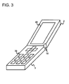
- Fig. 3 is a perspective view showing a state where the mobile electronic equipment 1 is opened.
- a display unit 20 is disposed on the opened surface of the first housing 2.
- the second housing 3 includes an operation unit 30.
- An operation on the mobile electronic equipment 1 by the user is performed through the operation unit 30.
- a necessary display is made on the display unit 20.
- a surface where the display unit 20 of the first housing 2 is present is referred to as a display surface, while a surface where the operation unit 30 of the second housing 3 is present is referred to as an operation surface.
- Fig. 4 is a side view of the mobile electronic equipment 1 according to this exemplary embodiment.
- the mobile electronic equipment 1 includes a gyro sensor 40 inside the first housing 2.
- Fig. 5 is a block diagram showing an inner configuration of the mobile electronic equipment 1 according to this embodiment.
- the mobile electronic equipment 1 shown in Fig. 5 is constituted from the gyro sensor 40, an opening/closing detection unit 50, a control unit 60, and a memory 70.
- a vibration-type gyro sensor is employed for the gyro sensor 40, and an output result of the gyro sensor 40 is notified to the control unit 60.
- the opening/closing detection unit 50 can detect whether or not the mobile electronic equipment 1 has started to move (an angle formed between the first housing and the second housing starts to change) from a state where the mobile electronic equipment 1 is closed (hereinafter referred to as a closed state) to a state where the mobile electronic equipment 1 is open (hereinafter referred to as an open state) and whether or not the movement to the open state has been finished (the change in the angle formed between the first housing and the second housing has been finished).
- the opening/closing detection unit 50 corresponds to the above-mentioned housing angle detection unit 104.
- the opening/closing detection unit 50 can detect a start of transition from the open state to the closed state and can also detect completion of the transition to the closed state.
- the control unit 60 performs control over the gyro sensor 40 and the opening/closing detection unit 50.
- the memory 70 stores information necessary for the mobile electronic equipment 1.
- the information in that case includes an offset correction value for correcting an output result of the gyro sensor 40.
- control unit 60 is constituted from an opening/closing detection driver 601, a gyro sensor driver 602, an opening/closing angle calculation unit 603, and an offset correction value calculation unit 604.
- the opening/closing detection driver 601 performs control over the opening/closing detection unit 50, and notifies the state of the mobile electronic equipment 1 (start or finish of movement) notified from the opening/closing detection unit 50 to the opening/closing angle calculation unit 603.
- the gyro sensor driver 602 performs control over the gyro sensor 40, and converts a voltage value output by the gyro sensor 40 to an angular velocity.
- the opening/closing angle calculation unit 603 controls the opening/closing detection driver 601 and the gyro sensor driver 602.
- the opening/closing angle calculation unit 603 receives the notification of the start of movement from the opening/closing detection driver 601, the opening/closing angle calculation unit 603 requests the gyro sensor 40 to perform angular velocity measurement through the gyro sensor driver 602.
- the offset correction value calculation unit 604 calculates a difference value between an angle (measured angle) notified from the opening/closing angle calculation unit 603 and a known angle (reference angle) between the operation surface and the display surface, and divides this difference value by a period of time needed for movement of the first housing 2.
- This value is an angular velocity offset value of the gyro sensor 40.
- this value is stored in the memory 70 as the offset correction value for the gyro sensor 40.
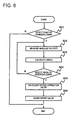
- Fig. 6 is a flowchart showing a procedure when the offset correction value for the gyro sensor 40 included in the mobile electronic equipment 1 is calculated.
- step S01 it is detected whether or not the mobile electronic equipment 1 has started moving from the closed state to the open state. That is, an operation of opening the mobile electronic equipment 1 by the user is detected.
- the opening/closing detection unit 50 detects the opening operation of the mobile electronic equipment 1. Then, the start of the opening operation of the mobile electronic equipment 1 is notified to the opening/closing detection driver 601.
- the opening/closing detection driver 601 that has received the notification notifies the opening/closing angle calculation unit 603 that the mobile electronic equipment 1 has started the opening operation.
- step S02 the opening/closing angle calculation unit 603 that has received the notification of the opening operation from the opening/closing detection driver 601 instructs the gyro sensor driver 602 to measure an angular velocity.
- the gyro sensor driver 602 that has received the instruction obtains the angular velocity from the gyro sensor 40.
- step S03 the gyro sensor driver 602 notifies the angular velocity obtained from the gyro sensor 40 to the opening/closing angle calculation unit 603.
- the opening/closing angle calculation unit 603 that has received the notification multiplies the angular velocity notified from the gyro sensor driver 602 by the measurement period (sampling period) of the gyro sensor 40, thereby calculating a change in the angle (hereinafter referred to as an angle change value) formed between the first housing 2 and the second housing 3.
- This angle change value is held in a register or the like.
- step S04 it is checked whether or not the movement of the mobile electronic equipment 1 to the open state has been finished.
- the opening/closing detection unit 50 detects the finish of the movement of the mobile electronic equipment 1 to the open state
- the opening/closing detection unit 50 notifies the detection to the opening/closing detection driver 601.
- the opening/closing detection driver 601 that has received the notification notifies the finish of movement of the mobile electronic equipment 1 to the open state to the opening/closing angle calculation unit 603.
- the opening/closing angle calculation unit 603 does not receive the notification of the finish of movement of the opening operation, a transition to the step S02 is made to repeat measurement of an angular velocity.
- the opening/closing angle calculation unit 603 adds a calculated angle change value to the angle change value held in the register or the like whenever the angle change value is calculated.
- the opening/closing angle calculation unit 603 receives the notification of the finish of the opening operation, the opening/closing angle calculation unit 603 notifies the angle change value held in the register or the like and a period of time taken from the start to the finish of the opening operation (hereinafter referred to as a rotation period) of the first housing 2 to the offset correction value calculation unit 604. Then, the procedure transitions to step S05.
- the offset correction value calculation unit 604 calculates a difference value between the angle change value notified from the opening/closing angle calculation unit 603 and an angle (hereinafter referred to as a reference angle) formed between the first housing 2 and the second housing 3 when the mobile electronic equipment 1 is properly opened.
- the angle change value received by the offset correction value calculation unit 604 is the one resulting from cumulative addition of values each derived from multiplication of the angular velocity obtained by the gyro sensor 40 by the measurement period of the angular velocity.
- the angle change value is equal to a measurement of the angle (measured angle) formed between the first housing 2 and the second housing 3 in the open state.
- the offset correction value calculation unit 604 receives the measured angle from the opening/closing angle calculation unit 603. Further, since the reference angle is a constant that has been set in the design stage of the mobile electronic equipment 1, the reference angle is stored in advance in the memory 70 or the like.
- a value obtained by dividing a difference value between the measured angle and the reference angle which is a known value by the rotation period notified from the opening/closing angle calculation unit 603 corresponds to an amount of offset drift of the gyro sensor 40. For that reason, when the offset drift value of the gyro sensor 40 is subtracted from the output result of the gyro sensor 40, correction of the gyro sensor 40 can be performed. That is, the offset drift amount can be regarded as the offset correction value for the gyro sensor 40.
- step S06 the offset correction value calculation unit 604 stores the calculated offset correction value in the memory 70.
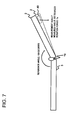
- Fig. 7 is a diagram for explaining a relationship between the measured angle calculated from the angular velocity obtained from the gyro sensor 40 and the angle (reference angle) actually formed between the first housing 2 and the second housing 3.
- a dotted line in Fig. 7 indicates the position of the first housing 2 estimated based on the output result of the gyro sensor 40.
- the reference angle formed between the first housing 2 and the second housing 3 in the open state of the mobile electronic equipment 1 is known in advance to be 150 degrees.
- the angular velocity offset correction value for the gyro sensor 40 can be calculated to be 50 degrees/second from (200 degrees - 150 degrees) ⁇ 1s. Accordingly, when various applications of the mobile electronic equipment 1 use the output result of the gyro sensor 40, a correct angular velocity can be obtained by subtracting 50 degrees/second from a measured value.
- the mounting position of the gyro sensor 40 will be described. Correction of the gyro sensor 40 may not be able to be performed, depending on a relationship between the mounting direction of the gyro sensor 40 and the opening/closing direction of the mobile electronic equipment 1. Assume that the gyro sensor 40 is a gyro sensor having only one detection axis. Then, an angular velocity in a direction orthogonal to the detection axis cannot be measured. That is, in the gyro sensor as shown in Fig. 8 , a Z axis is the detection axis, so that rotation based on an X axis or a Y axis cannot be detected.
- angular velocity measurement cannot be performed by using the gyro sensor 40.
- An offset correction value for the gyro sensor 40 cannot be therefore calculated.
- the gyro sensor 40 is mounted as shown in Fig. 9 .
- An axis A1 in Fig. 9 is an axis used when the first housing 2 of the mobile electronic equipment 1 moves, and an axis A2 is the detection axis of the gyro sensor 40.
- the gyro sensor 40 cannot detect the angular velocity of the mobile electronic equipment 1 even if the mobile electronic equipment 1 has performed an open or closing operation.
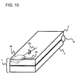
- the rotation axis of the first housing 2 and the detection axis of the gyro sensor 40 it is necessary not to cause the rotation axis of the first housing 2 and the detection axis of the gyro sensor 40 to be orthogonal when the gyro sensor 40 is mounted on the substrate of the mobile electronic equipment 1 or the like.
- the gyro sensor 40 is mounted so that a detection axis A3 of the gyro sensor 40 is not orthogonal to the rotation axis A1 of the mobile electronic equipment 1, as shown in Fig. 10 .
- the gyro sensor 40 is mounted shifted from the rotation axis of the first housing 2 by 45 degrees. Consequently, the angular velocity of the first housing 2 in a rotation direction can be detected.
- the above description was directed to a method of calculating the offset correction value for the gyro sensor 40 when the mobile electronic equipment 1 is transitioned from the closed state to the open state.
- An offset correction value for the gyro sensor 40 can be calculated by a similar method also when the mobile electronic equipment 1 transitions from the open state to the closed state.
- step S01 in Fig. 6 the opening/closing detection unit 50 detects a start of a closing operation instead of detecting the start of the opening operation. Then, in step S04, the opening/closing detection unit 50 detects a finish of detection of the closing operation instead of detecting the finish of the opening operation. Then, by notifying detection of each closing operation to the opening/closing detection driver 601, the offset correction value for the gyro sensor 40 can be detected also when the closing operation is performed.
- an offset correction value for the gyro sensor 40 can be calculated without requesting the user to perform a special operation.
- the second housing needs to be fixed while the user is moving the first housing in order to calculate a correct offset correction value.
- provision of a recess in the side surface of the second housing or the like may be considered to reduce fluctuation of the second housing while the user is moving the first housing.
- the mobile electronic equipment 1 includes an acceleration sensor and can detect the fluctuation of the second housing, a method of not employing (or cancelling) an offset correction value calculated in that case may be considered.
- an opening or closing operation to be performed when the user operates the mobile electronic equipment 1 calculating a difference between the reference angle that is the known value and an angle (measured angle) which is formed between the display surface and the operation surface and can be calculated from an angular velocity obtained by the gyro sensor 40, and then dividing the difference by a rotation period, an offset correction value for the gyro sensor 40 can be calculated. Consequently, an output result of the gyro sensor 40 with high accuracy can be obtained without causing the user to be aware of execution of calibration of the gyro sensor 40. A user-friendly mobile electronic equipment can be therefore provided.
- the offset value of the gyro sensor 40 does not greatly vary as long as ambient temperature around the gyro sensor 40 does not abruptly change.
- the opening or closing operation of the mobile electronic equipment is performed in an extremely short period of time compared with the change in the ambient temperature.
- influence of the change in the ambient temperature does not need to be taken into consideration.
- the description was given, assuming that the gyro sensor 40 has one detection axis. Similar offset correction is naturally possible for the gyro sensor having two or three detection axes.
- a mobile electronic equipment 1a according to this exemplary embodiment is not different from the mobile electronic equipment 1 in the first exemplary embodiment in its perspective. Thus, descriptions corresponding to those about Figs. 2 and 3 will be omitted.
- Fig. 11 is a block diagram showing an inner configuration of the mobile electronic equipment 1a according to this exemplary embodiment. Components in Fig. 11 that are the same as those in Fig. 5 are indicated by same reference signs, thereby omitting description of the components in Fig. 11 that are the same as those in Fig. 5 .
- the inner configuration of the mobile electronic equipment 1a shown in Fig. 11 is different from that of the mobile electronic equipment 1 in Fig. 5 in that the mobile electronic equipment 1a includes an opening start detection unit 80, a closing finish detection unit 90, and an opening start detection driver 605 and a closing stop detection driver 606 for controlling these detection units, in place of the opening/closing detection unit 50 and the opening/closing detection driver 601.
- a hinged portion 10a of the mobile electronic equipment 1a does not include a mechanism for detecting a rotation operation, thereby causing this difference.
- different detection units are respectively used for the opening operation and the closing operation.
- the opening start detection unit 80 detects a start of the opening operation of the mobile electronic equipment 1a.
- the opening start detection unit 80 is implemented by providing various sensors such as a Hall element, an illuminance sensor, a proximity sensor, and a pressure sensor, a mechanical switch, and the like inside the display surface or the operation surface, for example.
- the closing finish detection unit 90 is for detecting a finish of the opening operation of the mobile electronic equipment 1a.
- a detection method by the closing finish detection unit 90 using a start of an operation on the mobile electronic equipment 1a by a user as a trigger may be considered.
- a moment when the user has finished opening (operation) of the mobile electronic equipment 1a and has then first operated the mobile electronic equipment 1a using a touch panel unitarily disposed with the operation unit 30 and the display unit 20 is set to the finish of the opening operation of the mobile electronic equipment 1a.
- a period of time to be taken from a transition of the mobile electronic equipment 1a to an open state to execution of a key operation by the user does not cause influence on an offset correction value. It is because an output of the gyro sensor 40 while the gyro sensor 40 is not rotating is an offset value itself, and an offset correction value is derived from division of an angle change value by a period of time taken from a start of movement (transition) of the mobile electronic equipment 1a to the open state to the operation by the user, in which the angle change value is obtained by cumulative addition of offset values.
- Fig. 12 is a graph showing a change in angular velocity from a start of the opening operation of the mobile electronic equipment 1a to a key depression by the user.
- the reference angle is set to 150 degrees as in the case of Fig. 7
- an offset is set to 50 degrees/second.
- Fig. 12 shows a situation where the actual opening operation is completed (at a time t1) after one second from detection of the start of the opening operation of the mobile electronic equipment 1a by the opening start detection unit 80 and then the user has pressed the key after one second from the completion of the actual opening operation.
- the reference angle is set to 150 degrees
- the offset is set to 50 degrees.
- the measured angle at the time t1 will be 200 degrees.
- an offset correction value is calculated from (250 degrees - 150 degrees) ⁇ 2s, and can be determined to be 50 degrees/second.
- the open/closed state of the mobile electronic equipment can be determined, so that calibration of the gyro sensor 40 can be performed. Accordingly, it is not necessary to employ a new housing in order to detect the opening or closing operation. As a result, calibration of the gyro sensor can be implemented without increasing the product cost.
Landscapes
- Engineering & Computer Science (AREA)
- Physics & Mathematics (AREA)
- General Physics & Mathematics (AREA)
- Radar, Positioning & Navigation (AREA)
- Remote Sensing (AREA)
- Signal Processing (AREA)
- Manufacturing & Machinery (AREA)
- Telephone Function (AREA)
- Gyroscopes (AREA)
Abstract
Description
- This application is based upon and claims the benefit of the priority of Japanese patent application No.
2011-033012 filed on February 18, 2011
The present invention relates to a mobile electronic equipment with a gyro sensor, a gyro sensor correction method, and a program. More specifically, the invention relates to correction of the gyro sensor of a mobile electronic equipment in which a mode change can be made. - Recently, the number of mobile electronic equipments such as cellular phones including gyro sensors has increased. A gyro sensor has been used for a long time in order to achieve detection of the attitude of a mobile electronic equipment or to implement a navigation system. Further, recently, with high functionalization of the mobile electronic equipment, there is a strong demand for use of the gyro sensor to detect the rotational speed or the rotation angle of the mobile electronic equipment so as to implement an application for a game or health management (including detection of a manner of walking)
- The mobile electronic equipment often uses the gyro sensor of a type for detecting an angular velocity using a Coriolis force applied to a vibrating object. In such a gyro sensor, a zero-point offset will occur due to temperature change or change with time. Thus, calibration (calibration) is needed. It is because, when the gyro sensor is used without performing the calibration, measurement accuracy of the gyro sensor deteriorates, so that the gyro sensor is not workable.
-
Patent Literature 1 discloses a technique for transitioning a mobile electronic equipment to a usual power mode during a low power consumption mode of the mobile electronic equipment to execute calibration of a gyro sensor, even if the gyro sensor has not been used for a long time and a zero-point offset has occurred. -
- [PTL 1]
JP Patent Kokai Publication No. JP2010-152587A - The entire disclosure of
Patent Literature 1 is incorporated herein by reference. The following analysis has been made in terms of the present invention. - In principle, the zero-point offset occurs in the vibration-type gyro sensor, as mentioned above. In a state where an equipment including the gyro sensor is stationary, zero should be output from the gyro sensor. However, an offset (of a given value) is output, though the gyro sensor is stationary. This phenomenon is called the zero-point offset. This offset occurs even when the equipment including the gyro sensor is performing a rotating operation.
- For calibrating the offset, there may be considered the following method. In this method, the equipment including the gyro sensor is immobilized for several seconds, and a deviation of the zero point of the gyro sensor is measured and stored. Then, when using an output of the gyro sensor, the amount of the deviation is reflected on a value to be output from the gyro sensor. Such a calibration method, however, is acceptable if a gyro sensor mounted in an industrial equipment is calibrated. However, there is a problem with this method when this method is used for calibrating a gyro sensor mounted in an equipment such as a mobile electronic equipment.
- The reason for this problem is as follows. It is premised that the mobile electronic equipment is used by being carried around. Thus, creation of the stationary state of the mobile electronic equipment by a user leads to an operation that does not originally need to be aware of by the user. Thus, the user may feel inconvenience of the mobile electronic equipment.
- On the other hand, a change in ambient temperature around the mobile electronic equipment may also cause the offset of the gyro sensor. When the offset of the gyro sensor occurs due to a change in ambient temperature around the mobile electronic equipment, calibration of the gyro sensor may also be performed by using a temperature sensor. This calibration is a method in which the temperature sensor is operated simultaneously when the gyro sensor is used, and an output value of the gyro sensor is corrected according to the temperature detected by the temperature sensor. The gyro sensor has a temperature characteristic that is different for each of mobile electronic equipments. Thus, when such a calibration method is employed, it is necessary to obtain information on an offset value with respect to temperature for each of mobile electronic equipments because the temperature characteristic differs for each of mobile electronic equipments. A lot of inspection steps will be therefore generated so as to obtain this temperature characteristic of the gyro sensor for each of mobile electronic equipments, leading to an increase in the cost of the mobile electronic equipment. Thus, there is a problem with this calibration method.
- As described above, the related arts have the problems to be solved.
- In an aspect of the present invention, there are desired a mobile electronic equipment with a gyro sensor in which calibration of the gyro sensor is executed without a user being aware of the calibration, a correction method of the gyro sensor, and a program.
- According to a first aspect of the present invention, there is provided a mobile electronic equipment comprising: a gyro sensor that detects an angular velocity; a first housing with the gyro sensor disposed therein; a second housing movably connected to the first housing, an angle formed between the respective housings being changed by movement of the first housing; and a control unit that calculates a change in an angle formed between the first housing and the second housing before and after a movement as a measured angle, based on output data of the gyro sensor, and calculates a correction value for the output data of the gyro sensor based on the measured angle and a reference angle set in advance.
- According to a second aspect of the present invention, there is provided a method of correcting a gyro sensor of a mobile electronic equipment comprising: a gyro sensor that detects an angular velocity; a first housing with the gyro sensor disposed therein; and a second housing movably connected to the first housing, an angle formed between the respective housings being changed by movement of the first housing, the method comprising: calculating a change in an angle formed between the first housing and the second housing before and after a movement as a measured angle, based on output data of the gyro sensor; and calculating a correction value for the output data of the gyro sensor based on the measured angle and a reference angle set in advance. This method is associated with a specific machine, which is the mobile electronic equipment comprising the gyro sensor that detects the angular velocity, the first housing with the gyro sensor disposed therein, and the second housing movably connected to the first housing, the angle formed between the respective housings being changed by movement of the first housing.
- According to a third aspect of the present invention, there is provided a program for causing a computer that controls a mobile electronic equipment comprising: a gyro sensor that detects an angular velocity; a first housing with the gyro sensor disposed therein; and a second housing movably connected to the first housing, an angle formed between the respective housings being changed by movement of the first housing, the program causing the computer to execute processes of: calculating a change in an angle formed between the first housing and the second housing before and after a movement as a measured angle, based on output data of the gyro sensor; and calculating a correction value for the output data of the gyro sensor based on the measured angle and a reference angle set in advance. This program can be recorded in a computer readable storage medium. That is, the present invention can also be embodied as a computer program product. The storage medium can be set to a non-transient storage medium such as a semiconductor memory, a hard disk, a magnetic recording medium, or an optical recording medium.
- According to each aspect of the present invention, there are provided the mobile electronic equipment with the gyro sensor in which calibration of the gyro sensor is executed without a user being aware of the calibration, the correction method of the gyro sensor, and the program.
-
-
Fig. 1 is a diagram for explaining an overview of an exemplary embodiment. -
Fig. 2 is a perspective view showing a closed state of a mobile electronic equipment according to a first exemplary embodiment. -
Fig. 3 is a perspective view showing an open state of the mobile electronic equipment according to the first exemplary embodiment. -
Fig. 4 is a side view of the mobile electronic equipment according to the first exemplary embodiment. -
Fig. 5 is a block diagram showing an inner configuration of the mobile electronic equipment in the first exemplary embodiment. -
Fig. 6 is a flowchart showing a procedure when an offset correction value for a gyro sensor is calculated. -
Fig. 7 is a diagram for explaining a relationship between a measurement result obtained from the gyro sensor and an angle formed between a first housing and a second housing. -
Fig. 8 is a diagram for explaining a detection axis of the gyro sensor and a direction in which detection of an angular velocity is possible. -
Fig. 9 shows an example of disposition of the gyro sensor where movement of the first housing cannot be detected. -
Fig. 10 shows an example of disposition of the gyro sensor where movement of the first housing can be detected. -
Fig. 11 is a block diagram showing an inner configuration of a mobile electronic equipment in a second exemplary embodiment. -
Fig. 12 is a graph showing a change in angular velocity from a start of an opening operation of the mobile electronic equipment to key depression by a user. - First, an overview of an exemplary embodiment will be described, using
Fig. 1 . A reference sign in each of drawings appended to this overview is appended to each element as an example of help understanding, and does not intend to limit the present invention to the modes that have been illustrated. - In principle, an offset drift will occur in a gyro sensor, as described above. For that reason, calibration of the gyro sensor is essential for a mobile electronic equipment including the gyro sensor. However, when a user is forced to perform a special operation in order to perform the calibration, there is a problem in terms of convenience.
- Then, a mobile
electronic equipment 100 shown inFig. 1 is provided. The mobileelectronic equipment 100 shown inFig. 1 is constituted from a first housing 102 in which agyro sensor 101 is disposed and a second housing 103 connected to the first housing 102. Operating the mobileelectronic equipment 100 by the user to move the first housing 102 changes the mode of the mobileelectronic equipment 100 from the first mode to a second mode. When an angle formed between the first housing 102 and the second housing 103 changes, a start of the change of the angle can be detected by a housingangle detection unit 104. Further, the housingangle detection unit 104 can detect a finish of the change of the angle formed between the first housing 102 and the second housing 103. - A
control unit 105 in the mobileelectronic equipment 100 as described above repeats measurement of an angular velocity using thegyro sensor 101 when the angle formed between the first housing 102 and the second housing 103 starts to change. A change value of the angle formed between the second housing 103 and the first housing 102 which has moved during measurement of the angular velocity is obtained. Then, thecontrol unit 105 cumulatively adds the change value of the angle formed between the first housing 102 and the second housing 103 until the change of the angle is finished, thereby calculating a measured angle formed between the first housing 102 and the second housing 103. On the other hand, an angle to be formed between the first housing 102 and the second housing 103 when the mobileelectronic equipment 100 is set to the second mode is known in the design stage of the mobileelectronic equipment 100. Thus, this angle is stored in advance in the mobileelectronic equipment 100 as a reference angle. Then, by dividing a difference between the reference angle and the angle (measured angle) formed between the first housing 102 and the second housing 103 and then measured by thegyro sensor 101 by a period of time from the start to the finish of the change of the angle formed between the first housing 102 and the second housing 103, thecontrol unit 105 calculates an offset correction value for correcting the output error of thegyro sensor 101. - As described above, calibration of the gyro sensor is executed during the operation that is naturally executed when the user operates the mobile electronic equipment. Thus, the user will not be aware that the calibration of the gyro sensor has been executed. Further, when using a result of measurement by the gyro sensor, an output of the gyro sensor is corrected, based on the offset correction value. The angular velocity and the angle of the mobile electronic equipment with high accuracy can be thereby obtained. A user-friendly mobile electronic equipment can be therefore provided.
- According to the present invention, the following modes are possible.
- See the mobile electronic equipment according to the first aspect described above.
- Preferably, the first housing and the second housing may form a first mode and a second mode;
the mobile electronic equipment further comprises: - a housing angle detection unit that may detect a start and a finish of a change in an angle formed between the first housing and the second housing in each of the first mode and the second mode; and
- the control unit calculates the measured angle from a value of change in angular velocity during a period of time from the start to the finish of the change in the angle.
- Preferably, when the housing angle detection unit detects a start of a change in the angle, the control unit repeats angular velocity acquisition using the gyro sensor, calculates a value of the change in the angle formed between the first housing and the second housing from a period of time in which the first housing moves during the angular velocity acquisition, and then calculates the measured angle from a value of the change in the angle when the housing angle detection unit detects a finish of the change in the angle.
- Preferably, the control unit divides a value obtained by subtracting the reference angle from the measured angle by the period of time from the start to the finish of the change in the angle detected by the housing operation detection unit, thereby calculating a correction value.
- Preferably, in the gyro sensor, an angular velocity detection axis of the gyro sensor and a base axis for movement of the first housing are disposed not to be orthogonal.
- Preferably, the first mode is a mode in which the first housing and the second housing are roughly in close contact with each other; and the second mode is a mode in which the first housing and the second housing form a given angle centering on a connecting point between the first housing and the second housing, and are fixed.
- Preferably, the housing operation detection unit comprises:
- an angle change start detection unit that detects a start of the change in the angle; and
- an angle change finish detection unit that detects a finish of the change in the angle.
- Preferably, the angle change finish detection unit detects the finish of the change in the angle, based on an operation by a user.
- Preferably, the gyro sensor is a vibration-type gyro sensor.
- Preferably, the second housing may be fixed by the user during a period of time from the start to the finish of the change in the angle.
- Preferably, when the control unit detects that the second housing is not fixed during a period of time from the start to the finish of the change in the angle, the control unit does not calculate the correction value.
- Preferably, the first mode is a closed state of the mobile electronic equipment that is foldable, and the second mode is an open state of the mobile electronic equipment that is foldable.
- See the method of correcting a gyro sensor of a mobile electronic equipment according to the second aspect described above.
- Preferably, the first housing and the second housing may form a first mode and a second mode;
the mobile electronic equipment further comprises: - a housing angle detection unit that may detect a start and a finish of the change in the angle formed between the first housing and the second housing in each of the first mode and the second mode; and the method of correcting a gyro sensor of a mobile electronic equipment further comprises the step of:
- calculating the measured angle from a value of a change in angular velocity during a period of time from the start to the finish of the change in the angle.
- Preferably, the method of correcting a gyro sensor of a mobile electronic equipment further comprising the step of:
- repeating angular velocity acquisition using the gyro sensor, and then calculating a value of a change in the angle from a period of time in which the first housing moves during the angular velocity acquisition, when the housing angle detection unit further detects a start of the change in the angle.
- Preferably, a value obtained by subtracting a reference angle from the measured angle is divided by a period of time from the start to the finish of the change in the angle detected by the housing operation detection unit, thereby calculating the correction value.
- See the program according to the third aspect described above.
- Preferably, the first housing and the second housing may form a first mode and a second mode;
the mobile electronic equipment further comprises: - a housing angle detection unit that may detect a start and a finish of the change in the angle formed between the first housing and the second housing in each of the first mode and the second mode; and in the program, the process of calculating the measured angle is executed using a value of a change in the angular velocity during a period of time from a start to a finish of the change in the angle.
- Preferably, in the program, the process of repeating angular velocity acquisition using the gyro sensor and then calculating a value of a change in the angle from a period of time in which the first housing moves during the angular velocity acquisition is executed, when the housing angle detection unit further detects a start of the change in the angle.
- Preferably, in the program, a value obtained by subtracting a reference angle from the measured angle is divided by the period of time from the start to the finish of the change in the angle detected by the housing operation detection unit, thereby calculating the correction value.
- Next, a first exemplary embodiment will be described in detail using drawings.
Fig. 2 is a perspective view showing a mobileelectronic equipment 1 in a closed state according to this exemplary embodiment. The mobile electronic equipment shown inFig. 2 is constituted from afirst housing 2 and asecond housing 3. The mobileelectronic equipment 1 can be folded with respect to a hingedportion 10. Opening and closing of the mobileelectronic equipment 1 is performed by grasping thefirst housing 2 and moving the first housing upward by a user. A hinged portion having a mechanism for detecting a rotation operation is employed as the hingedportion 10. -
Fig. 3 is a perspective view showing a state where the mobileelectronic equipment 1 is opened. Adisplay unit 20 is disposed on the opened surface of thefirst housing 2. Thesecond housing 3 includes anoperation unit 30. An operation on the mobileelectronic equipment 1 by the user is performed through theoperation unit 30. A necessary display is made on thedisplay unit 20. A surface where thedisplay unit 20 of thefirst housing 2 is present is referred to as a display surface, while a surface where theoperation unit 30 of thesecond housing 3 is present is referred to as an operation surface. -
Fig. 4 is a side view of the mobileelectronic equipment 1 according to this exemplary embodiment. The mobileelectronic equipment 1 includes agyro sensor 40 inside thefirst housing 2. -
Fig. 5 is a block diagram showing an inner configuration of the mobileelectronic equipment 1 according to this embodiment. The mobileelectronic equipment 1 shown inFig. 5 is constituted from thegyro sensor 40, an opening/closing detection unit 50, acontrol unit 60, and amemory 70. - A vibration-type gyro sensor is employed for the
gyro sensor 40, and an output result of thegyro sensor 40 is notified to thecontrol unit 60. - The opening/
closing detection unit 50 can detect whether or not the mobileelectronic equipment 1 has started to move (an angle formed between the first housing and the second housing starts to change) from a state where the mobileelectronic equipment 1 is closed (hereinafter referred to as a closed state) to a state where the mobileelectronic equipment 1 is open (hereinafter referred to as an open state) and whether or not the movement to the open state has been finished (the change in the angle formed between the first housing and the second housing has been finished). The opening/closing detection unit 50 corresponds to the above-mentioned housingangle detection unit 104. As a method of detecting the state of the mobileelectronic equipment 1 by the opening/closing detection unit 50, a method of detecting the state of the mobileelectronic equipment 1 by the rotation mechanism of the hingedportion 10 may be considered. The opening/closing detection unit 50 can detect a start of transition from the open state to the closed state and can also detect completion of the transition to the closed state. - The
control unit 60 performs control over thegyro sensor 40 and the opening/closing detection unit 50. - The
memory 70 stores information necessary for the mobileelectronic equipment 1. The information in that case includes an offset correction value for correcting an output result of thegyro sensor 40. - Further, the
control unit 60 is constituted from an opening/closing detection driver 601, agyro sensor driver 602, an opening/closingangle calculation unit 603, and an offset correctionvalue calculation unit 604. - The opening/
closing detection driver 601 performs control over the opening/closing detection unit 50, and notifies the state of the mobile electronic equipment 1 (start or finish of movement) notified from the opening/closing detection unit 50 to the opening/closingangle calculation unit 603. - The
gyro sensor driver 602 performs control over thegyro sensor 40, and converts a voltage value output by thegyro sensor 40 to an angular velocity. - The opening/closing
angle calculation unit 603 controls the opening/closing detection driver 601 and thegyro sensor driver 602. When the opening/closingangle calculation unit 603 receives the notification of the start of movement from the opening/closing detection driver 601, the opening/closingangle calculation unit 603 requests thegyro sensor 40 to perform angular velocity measurement through thegyro sensor driver 602. - The offset correction
value calculation unit 604 calculates a difference value between an angle (measured angle) notified from the opening/closingangle calculation unit 603 and a known angle (reference angle) between the operation surface and the display surface, and divides this difference value by a period of time needed for movement of thefirst housing 2. This value is an angular velocity offset value of thegyro sensor 40. Thus, this value is stored in thememory 70 as the offset correction value for thegyro sensor 40. - Next, operation of the mobile
electronic equipment 1 according to this exemplary embodiment will be described.Fig. 6 is a flowchart showing a procedure when the offset correction value for thegyro sensor 40 included in the mobileelectronic equipment 1 is calculated. - In step S01, it is detected whether or not the mobile
electronic equipment 1 has started moving from the closed state to the open state. That is, an operation of opening the mobileelectronic equipment 1 by the user is detected. When the user tries to open the mobileelectronic equipment 1, the opening/closing detection unit 50 detects the opening operation of the mobileelectronic equipment 1. Then, the start of the opening operation of the mobileelectronic equipment 1 is notified to the opening/closing detection driver 601. The opening/closing detection driver 601 that has received the notification notifies the opening/closingangle calculation unit 603 that the mobileelectronic equipment 1 has started the opening operation. - In step S02, the opening/closing
angle calculation unit 603 that has received the notification of the opening operation from the opening/closing detection driver 601 instructs thegyro sensor driver 602 to measure an angular velocity. Thegyro sensor driver 602 that has received the instruction obtains the angular velocity from thegyro sensor 40. - In step S03, the
gyro sensor driver 602 notifies the angular velocity obtained from thegyro sensor 40 to the opening/closingangle calculation unit 603. The opening/closingangle calculation unit 603 that has received the notification multiplies the angular velocity notified from thegyro sensor driver 602 by the measurement period (sampling period) of thegyro sensor 40, thereby calculating a change in the angle (hereinafter referred to as an angle change value) formed between thefirst housing 2 and thesecond housing 3. This angle change value is held in a register or the like. - In step S04, it is checked whether or not the movement of the mobile
electronic equipment 1 to the open state has been finished. When the opening/closing detection unit 50 detects the finish of the movement of the mobileelectronic equipment 1 to the open state, the opening/closing detection unit 50 notifies the detection to the opening/closing detection driver 601. The opening/closing detection driver 601 that has received the notification notifies the finish of movement of the mobileelectronic equipment 1 to the open state to the opening/closingangle calculation unit 603. When the opening/closingangle calculation unit 603 does not receive the notification of the finish of movement of the opening operation, a transition to the step S02 is made to repeat measurement of an angular velocity. In that case, the opening/closingangle calculation unit 603 adds a calculated angle change value to the angle change value held in the register or the like whenever the angle change value is calculated. When the opening/closingangle calculation unit 603 receives the notification of the finish of the opening operation, the opening/closingangle calculation unit 603 notifies the angle change value held in the register or the like and a period of time taken from the start to the finish of the opening operation (hereinafter referred to as a rotation period) of thefirst housing 2 to the offset correctionvalue calculation unit 604. Then, the procedure transitions to step S05. - In step S05, the offset correction
value calculation unit 604 calculates a difference value between the angle change value notified from the opening/closingangle calculation unit 603 and an angle (hereinafter referred to as a reference angle) formed between thefirst housing 2 and thesecond housing 3 when the mobileelectronic equipment 1 is properly opened. Herein, the angle change value received by the offset correctionvalue calculation unit 604 is the one resulting from cumulative addition of values each derived from multiplication of the angular velocity obtained by thegyro sensor 40 by the measurement period of the angular velocity. Thus, the angle change value is equal to a measurement of the angle (measured angle) formed between thefirst housing 2 and thesecond housing 3 in the open state. Accordingly, the offset correctionvalue calculation unit 604 receives the measured angle from the opening/closingangle calculation unit 603. Further, since the reference angle is a constant that has been set in the design stage of the mobileelectronic equipment 1, the reference angle is stored in advance in thememory 70 or the like. - A value obtained by dividing a difference value between the measured angle and the reference angle which is a known value by the rotation period notified from the opening/closing
angle calculation unit 603 corresponds to an amount of offset drift of thegyro sensor 40. For that reason, when the offset drift value of thegyro sensor 40 is subtracted from the output result of thegyro sensor 40, correction of thegyro sensor 40 can be performed. That is, the offset drift amount can be regarded as the offset correction value for thegyro sensor 40. - In step S06, the offset correction
value calculation unit 604 stores the calculated offset correction value in thememory 70. - Now, a relationship among the measured angle, the reference angle, and the offset correction value derived from these angles will be described, using
Fig. 7. Fig. 7 is a diagram for explaining a relationship between the measured angle calculated from the angular velocity obtained from thegyro sensor 40 and the angle (reference angle) actually formed between thefirst housing 2 and thesecond housing 3. A dotted line inFig. 7 indicates the position of thefirst housing 2 estimated based on the output result of thegyro sensor 40. Assume that, when the mobileelectronic equipment 1 is in the open state as inFig. 7 , the measured angle and the rotation period notified to the offset correctionvalue calculation unit 604 are 200 degrees and one second, respectively. Then, the reference angle formed between thefirst housing 2 and thesecond housing 3 in the open state of the mobileelectronic equipment 1 is known in advance to be 150 degrees. Thus, the angular velocity offset correction value for thegyro sensor 40 can be calculated to be 50 degrees/second from (200 degrees - 150 degrees) ÷ 1s. Accordingly, when various applications of the mobileelectronic equipment 1 use the output result of thegyro sensor 40, a correct angular velocity can be obtained by subtracting 50 degrees/second from a measured value. - Next, the mounting position of the
gyro sensor 40 will be described. Correction of thegyro sensor 40 may not be able to be performed, depending on a relationship between the mounting direction of thegyro sensor 40 and the opening/closing direction of the mobileelectronic equipment 1. Assume that thegyro sensor 40 is a gyro sensor having only one detection axis. Then, an angular velocity in a direction orthogonal to the detection axis cannot be measured. That is, in the gyro sensor as shown inFig. 8 , a Z axis is the detection axis, so that rotation based on an X axis or a Y axis cannot be detected. For that reason, when the rotation direction of thefirst housing 2 is orthogonal to the detection axis of thegyro sensor 40 in the mobileelectronic equipment 1, angular velocity measurement cannot be performed by using thegyro sensor 40. An offset correction value for thegyro sensor 40 cannot be therefore calculated. Assume that thegyro sensor 40 is mounted as shown inFig. 9 . An axis A1 inFig. 9 is an axis used when thefirst housing 2 of the mobileelectronic equipment 1 moves, and an axis A2 is the detection axis of thegyro sensor 40. When the axis A1 and the axis A2 are in an orthogonal relationship, thegyro sensor 40 cannot detect the angular velocity of the mobileelectronic equipment 1 even if the mobileelectronic equipment 1 has performed an open or closing operation. - Then, it is necessary not to cause the rotation axis of the
first housing 2 and the detection axis of thegyro sensor 40 to be orthogonal when thegyro sensor 40 is mounted on the substrate of the mobileelectronic equipment 1 or the like. Thegyro sensor 40 is mounted so that a detection axis A3 of thegyro sensor 40 is not orthogonal to the rotation axis A1 of the mobileelectronic equipment 1, as shown inFig. 10 . Referring toFig. 10 , thegyro sensor 40 is mounted shifted from the rotation axis of thefirst housing 2 by 45 degrees. Consequently, the angular velocity of thefirst housing 2 in a rotation direction can be detected. - The above description was directed to a method of calculating the offset correction value for the
gyro sensor 40 when the mobileelectronic equipment 1 is transitioned from the closed state to the open state. An offset correction value for thegyro sensor 40 can be calculated by a similar method also when the mobileelectronic equipment 1 transitions from the open state to the closed state. - That is, in step S01 in
Fig. 6 , the opening/closing detection unit 50 detects a start of a closing operation instead of detecting the start of the opening operation. Then, in step S04, the opening/closing detection unit 50 detects a finish of detection of the closing operation instead of detecting the finish of the opening operation. Then, by notifying detection of each closing operation to the opening/closing detection driver 601, the offset correction value for thegyro sensor 40 can be detected also when the closing operation is performed. For that reason, even if the mobileelectronic equipment 1 has been kept in the opened state for a long period of time and calibration of thegyro sensor 40 is necessary, an offset correction value for thegyro sensor 40 can be calculated without requesting the user to perform a special operation. - The second housing needs to be fixed while the user is moving the first housing in order to calculate a correct offset correction value. Thus, provision of a recess in the side surface of the second housing or the like may be considered to reduce fluctuation of the second housing while the user is moving the first housing. Further, when the mobile
electronic equipment 1 includes an acceleration sensor and can detect the fluctuation of the second housing, a method of not employing (or cancelling) an offset correction value calculated in that case may be considered. - As described above, by using an opening or closing operation to be performed when the user operates the mobile
electronic equipment 1, calculating a difference between the reference angle that is the known value and an angle (measured angle) which is formed between the display surface and the operation surface and can be calculated from an angular velocity obtained by thegyro sensor 40, and then dividing the difference by a rotation period, an offset correction value for thegyro sensor 40 can be calculated. Consequently, an output result of thegyro sensor 40 with high accuracy can be obtained without causing the user to be aware of execution of calibration of thegyro sensor 40. A user-friendly mobile electronic equipment can be therefore provided. - The offset value of the
gyro sensor 40 does not greatly vary as long as ambient temperature around thegyro sensor 40 does not abruptly change. On the other hand, the opening or closing operation of the mobile electronic equipment is performed in an extremely short period of time compared with the change in the ambient temperature. Thus, influence of the change in the ambient temperature does not need to be taken into consideration. In this exemplary embodiment, the description was given, assuming that thegyro sensor 40 has one detection axis. Similar offset correction is naturally possible for the gyro sensor having two or three detection axes. - Next, a second exemplary embodiment will be described in detail with reference to drawings. A mobile electronic equipment 1a according to this exemplary embodiment is not different from the mobile
electronic equipment 1 in the first exemplary embodiment in its perspective. Thus, descriptions corresponding to those aboutFigs. 2 and3 will be omitted. -
Fig. 11 is a block diagram showing an inner configuration of the mobile electronic equipment 1a according to this exemplary embodiment. Components inFig. 11 that are the same as those inFig. 5 are indicated by same reference signs, thereby omitting description of the components inFig. 11 that are the same as those inFig. 5 . The inner configuration of the mobile electronic equipment 1a shown inFig. 11 is different from that of the mobileelectronic equipment 1 inFig. 5 in that the mobile electronic equipment 1a includes an openingstart detection unit 80, a closingfinish detection unit 90, and an openingstart detection driver 605 and a closingstop detection driver 606 for controlling these detection units, in place of the opening/closing detection unit 50 and the opening/closing detection driver 601. A hinged portion 10a of the mobile electronic equipment 1a does not include a mechanism for detecting a rotation operation, thereby causing this difference. In order to detect both of an opening operation and a closing operation, different detection units are respectively used for the opening operation and the closing operation. - The opening
start detection unit 80 detects a start of the opening operation of the mobile electronic equipment 1a. The openingstart detection unit 80 is implemented by providing various sensors such as a Hall element, an illuminance sensor, a proximity sensor, and a pressure sensor, a mechanical switch, and the like inside the display surface or the operation surface, for example. - The closing
finish detection unit 90 is for detecting a finish of the opening operation of the mobile electronic equipment 1a. As a detection method by the closingfinish detection unit 90, using a start of an operation on the mobile electronic equipment 1a by a user as a trigger may be considered. To take an example, a moment when the user has finished opening (operation) of the mobile electronic equipment 1a and has then first operated the mobile electronic equipment 1a using a touch panel unitarily disposed with theoperation unit 30 and thedisplay unit 20 is set to the finish of the opening operation of the mobile electronic equipment 1a. - A period of time to be taken from a transition of the mobile electronic equipment 1a to an open state to execution of a key operation by the user does not cause influence on an offset correction value. It is because an output of the
gyro sensor 40 while thegyro sensor 40 is not rotating is an offset value itself, and an offset correction value is derived from division of an angle change value by a period of time taken from a start of movement (transition) of the mobile electronic equipment 1a to the open state to the operation by the user, in which the angle change value is obtained by cumulative addition of offset values. -
Fig. 12 is a graph showing a change in angular velocity from a start of the opening operation of the mobile electronic equipment 1a to a key depression by the user. Assume that the reference angle is set to 150 degrees as in the case ofFig. 7 , and an offset is set to 50 degrees/second.Fig. 12 shows a situation where the actual opening operation is completed (at a time t1) after one second from detection of the start of the opening operation of the mobile electronic equipment 1a by the openingstart detection unit 80 and then the user has pressed the key after one second from the completion of the actual opening operation. In this case, the reference angle is set to 150 degrees, and the offset is set to 50 degrees. Thus, the measured angle at the time t1 will be 200 degrees. Further, the key depression by the user is performed after one second from the time t1. Thus, a final measured angle is 250 degrees. Consequently, an offset correction value is calculated from (250 degrees - 150 degrees) ÷ 2s, and can be determined to be 50 degrees/second. - As described above, even if the opening or closing operation of the mobile electronic equipment cannot be detected by the mechanism, the open/closed state of the mobile electronic equipment can be determined, so that calibration of the
gyro sensor 40 can be performed. Accordingly, it is not necessary to employ a new housing in order to detect the opening or closing operation. As a result, calibration of the gyro sensor can be implemented without increasing the product cost. - Each disclosure of the above-listed cited Patent Literature and the like is incorporated herein by reference. Modification and adjustment of each exemplary embodiment and each example are possible within the scope of the overall disclosure (including the claims) of the present invention and based on the technical concept of the present invention. Various combinations and selections of various disclosed elements (including each element in each claim, each element in each exemplary embodiment and each example, and each element in each drawing) are possible within the scope of the claims of the present invention. That is, the present invention naturally includes various variations and modifications that could be made by those skilled in the art according to the overall disclosure including the claims and the technical concept. To take an example, the mobile electronic equipment of a folding type was used as an example in the description of each exemplary embodiment. Correction of a gyro sensor is possible in a mobile electronic equipment including a rotation axis, of which a mode is changed and where an angle that is formed between housings before and after the change is known in advance.
-
- 1, 1a, 100
- mobile electronic equipment
- 2, 102
- first housing
- 3, 103
- second housing
- 10, 10a
- hinged portion
- 20
- display unit
- 30
- operation unit
- 40, 101
- gyro sensor
- 50
- opening/closing detection unit
- 60, 60a, 105
- control unit
- 70
- memory
- 80
- opening start detection unit
- 90
- closing finish detection unit
- 104
- housing angle detection unit
- 601
- opening/closing detection driver
- 602
- gyro sensor driver
- 603
- opening/closing angle calculation unit
- 604
- offset correction value calculation unit
- 605
- opening start detection driver
- 606
- closing stop detection driver
Claims (20)
- A mobile electronic equipment, comprising:a gyro sensor that detects an angular velocity;a first housing with the gyro sensor disposed therein;a second housing movably connected to the first housing, an angle formed between the respective housings being changed by movement of the first housing; anda control unit that calculates change in an angle formed between the first housing and the second housing before and after a movement as a measured angle, based on output data of the gyro sensor, and calculates a correction value for the output data of the gyro sensor based on the measured angle and a reference angle set in advance.
- The mobile electronic equipment according to claim 1, wherein
the first housing and the second housing may form a first mode and a second mode;
the mobile electronic equipment further comprises:a housing angle detection unit that may detect a start and a finish of a change in an angle formed between the first housing and the second housing in each of the first mode and the second mode; andthe control unit calculates the measured angle from a value of change in angular velocity during a period of time from the start to the finish of the change in the angle. - The mobile electronic equipment according to claim 2, wherein
when the housing angle detection unit detects a start of a change in the angle, the control unit repeats angular velocity acquisition using the gyro sensor, calculates a value of the change in the angle formed between the first housing and the second housing from a period of time in which the first housing moves during the angular velocity acquisition, and then calculates the measured angle from a value of the change in the angle when the housing angle detection unit detects a finish of the change in the angle. - The mobile electronic equipment according to claim 2 or 3, wherein
the control unit divides a value obtained by subtracting the reference angle from the measured angle by the period of time from the start to the finish of the change in the angle detected by the housing operation detection unit, thereby calculating a correction value. - The mobile electronic equipment according to any one of claims 1 to 4, wherein
in the gyro sensor, an angular velocity detection axis of the gyro sensor and a base axis for movement of the first housing are disposed not to be orthogonal. - The mobile electronic equipment according to any one of claims 2 to 5, wherein
the first mode is a mode in which the first housing and the second housing are roughly in close contact with each other; and
the second mode is a mode in which the first housing and the second housing form a given angle centering on a connecting point between the first housing and the second housing, and are fixed. - The mobile electronic equipment according to any one of claims 2 to 6, wherein
the housing operation detection unit comprises:an angle change start detection unit that detects a start of the change in the angle; andan angle change finish detection unit that detects a finish of the change in the angle. - The mobile electronic equipment according to claim 7, wherein
the angle change finish detection unit detects the finish of the change in the angle, based on an operation by a user. - The mobile electronic equipment according to any one of claims 1 to 8, wherein
the gyro sensor is a vibration-type gyro sensor. - The mobile electronic equipment according to any one of claims 2 to 9, wherein
the second housing may be fixed by the user during a period of time from the start to the finish of the change in the angle. - The mobile electronic equipment according to any one of claims 2 to 10, wherein
when the control unit detects that the second housing is not fixed during a period of time from the start to the finish of the change in the angle, the control unit does not calculate the correction value. - The mobile electronic equipment according to any one of claims 2 to 11, wherein
the first mode is a closed state of the mobile electronic equipment that is foldable, and the second mode is an open state of the mobile electronic equipment that is foldable. - A method of correcting a gyro sensor of a mobile electronic equipment, comprising:a gyro sensor that detects an angular velocity;a first housing with the gyro sensor disposed therein; anda second housing movably connected to the first housing, an angle formed between the respective housings being changed by movement of the first housing, the method comprising:calculating change in an angle formed between the first housing and the second housing before and after a movement as a measured angle, based on output data of the gyro sensor; andcalculating a correction value for the output data of the gyro sensor based on the measured angle and a reference angle set in advance.
- The method of correcting a gyro sensor of a mobile electronic equipment according to claim 13, wherein
the first housing and the second housing may form a first mode and a second mode;
the mobile electronic equipment further comprises:a housing angle detection unit that may detect a start and a finish of the change in the angle formed between the first housing and the second housing in each of the first mode and the second mode; andthe method of correcting a gyro sensor of a mobile electronic equipment further comprises the step of:calculating the measured angle from a value of a change in angular velocity during a period of time from the start to the finish of the change in the angle. - The method of correcting a gyro sensor of a mobile electronic equipment according to claim 14, further comprising the step of:repeating angular velocity acquisition using the gyro sensor, and then calculating a value of a change in the angle from a period of time in which the first housing moves during the angular velocity acquisition, when the housing angle detection unit further detects a start of the change in the angle.
- The method of correcting a gyro sensor of a mobile electronic equipment according to claim 14 or 15, wherein
a value obtained by subtracting a reference angle from the measured angle is divided by a period of time from the start to the finish of the change in the angle detected by the housing operation detection unit, thereby calculating the correction value. - A program for causing a computer that controls a mobile electronic equipment, comprising:a gyro sensor that detects an angular velocity;a first housing with the gyro sensor disposed therein; anda second housing movably connected to the first housing, an angle formed between the respective housings being changed by movement of the first housing, the program causing the computer to execute processes of:calculating change in an angle formed between the first housing and the second housing before and after a movement as a measured angle, based on output data of the gyro sensor; andcalculating a correction value for the output data of the gyro sensor based on the measured angle and a reference angle set in advance.
- The program according to claim 17, wherein
the first housing and the second housing may form a first mode and a second mode;
the mobile electronic equipment further comprises:a housing angle detection unit that may detect a start and a finish of the change in the angle formed between the first housing and the second housing in each of the first mode and the second mode; andthe process of calculating the measured angle is executed using a value of a change in the angular velocity during a period of time from a start to the finish of a change in the angle. - The program according to claim 18, wherein
when the housing angle detection unit further detects a start of a change in the angle, the process of repeating angular velocity acquisition using the gyro sensor and then calculating a value of the change in the angle from a period of time in which the first housing moves during the angular velocity acquisition is executed. - The program according to claim 18 or 19, wherein
a value obtained by subtracting a reference angle from the measured angle is divided by the period of time from the start to the finish of the change in the angle detected by the housing operation detection unit, thereby calculating the correction value.
Applications Claiming Priority (2)
| Application Number | Priority Date | Filing Date | Title |
|---|---|---|---|
| JP2011033012 | 2011-02-18 | ||
| PCT/JP2012/053768 WO2012111793A1 (en) | 2011-02-18 | 2012-02-17 | Portable electronic device with gyro sensor, correction method for gyro sensor, and program |
Publications (2)
| Publication Number | Publication Date |
|---|---|
| EP2677276A1 true EP2677276A1 (en) | 2013-12-25 |
| EP2677276A4 EP2677276A4 (en) | 2017-12-27 |
Family
ID=46672704
Family Applications (1)
| Application Number | Title | Priority Date | Filing Date |
|---|---|---|---|
| EP12747354.4A Withdrawn EP2677276A4 (en) | 2011-02-18 | 2012-02-17 | Portable electronic device with gyro sensor, correction method for gyro sensor, and program |
Country Status (5)
| Country | Link |
|---|---|
| US (1) | US9933260B2 (en) |
| EP (1) | EP2677276A4 (en) |
| JP (1) | JP5924271B2 (en) |
| CN (1) | CN103370602B (en) |
| WO (1) | WO2012111793A1 (en) |
Cited By (2)
| Publication number | Priority date | Publication date | Assignee | Title |
|---|---|---|---|---|
| EP2966854A4 (en) * | 2013-03-06 | 2016-10-26 | Nec Corp | IMAGE FORMING DEVICE, IMAGE FORMING METHOD, AND PROGRAM |
| EP2998702A4 (en) * | 2013-05-15 | 2017-01-11 | Asahi Kasei Kabushiki Kaisha | Offset estimation device, method, and program |
Families Citing this family (9)
| Publication number | Priority date | Publication date | Assignee | Title |
|---|---|---|---|---|
| JP6331356B2 (en) * | 2013-11-25 | 2018-05-30 | セイコーエプソン株式会社 | Detection device, sensor, electronic device, and moving object |
| JP2016031283A (en) * | 2014-07-29 | 2016-03-07 | 日本無線株式会社 | Angular velocity sensor device and method for correcting angular velocity sensor |
| KR102537922B1 (en) * | 2015-09-11 | 2023-05-30 | 삼성전자 주식회사 | Method for measuring angles between displays and Electronic device using the same |
| TW201939808A (en) * | 2018-03-02 | 2019-10-01 | 和碩聯合科技股份有限公司 | Antenna power adjustment method |
| IT201800004602A1 (en) * | 2018-04-17 | 2019-10-17 | Improved temperature measurement system in a harsh atmosphere with energy saving | |
| KR102765540B1 (en) | 2019-03-14 | 2025-02-12 | 삼성전자주식회사 | Electronic device including haptic actuator |
| CN111337053B (en) * | 2020-03-27 | 2021-09-14 | 中国科学院西安光学精密机械研究所 | Method and system for measuring and calibrating dynamic error characteristics of fiber-optic gyroscope |
| CN113063442B (en) * | 2021-03-17 | 2024-06-07 | 深圳市云鼠科技开发有限公司 | Method and device for calibrating gyroscope of sweeping robot, computer equipment and memory |
| CN119731612A (en) | 2022-08-16 | 2025-03-28 | 三星电子株式会社 | Flexible electronic device and operation method thereof |
Family Cites Families (7)
| Publication number | Priority date | Publication date | Assignee | Title |
|---|---|---|---|---|
| JPH02247521A (en) * | 1989-03-20 | 1990-10-03 | Nec Home Electron Ltd | Method for correcting angular velocity sensor |
| JP3431231B2 (en) * | 1993-09-06 | 2003-07-28 | クラリオン株式会社 | Gyro drift correction method and its correction circuit |
| JPH10122865A (en) * | 1996-10-22 | 1998-05-15 | Japan Aviation Electron Ind Ltd | Method for detecting and measuring rotational angular velocity and gyro for implementing the method |
| JP2006234710A (en) * | 2005-02-28 | 2006-09-07 | Seiko Epson Corp | Gyro signal detection device |
| JP2007040765A (en) * | 2005-08-01 | 2007-02-15 | Toyota Motor Corp | Zero point correction device for angular velocity sensor |
| JP2010152587A (en) | 2008-12-25 | 2010-07-08 | Sony Corp | Input device, control system, handheld device and calibration method |
| JP2011064594A (en) * | 2009-09-17 | 2011-03-31 | Sony Corp | Angular velocity correction device, angular velocity correction method, navigation device, and cellular phone having navigation function |
-
2012
- 2012-02-17 JP JP2012558032A patent/JP5924271B2/en not_active Expired - Fee Related
- 2012-02-17 CN CN201280009174.3A patent/CN103370602B/en not_active Expired - Fee Related
- 2012-02-17 EP EP12747354.4A patent/EP2677276A4/en not_active Withdrawn
- 2012-02-17 US US14/000,078 patent/US9933260B2/en not_active Expired - Fee Related
- 2012-02-17 WO PCT/JP2012/053768 patent/WO2012111793A1/en not_active Ceased
Non-Patent Citations (1)
| Title |
|---|
| See references of WO2012111793A1 * |
Cited By (2)
| Publication number | Priority date | Publication date | Assignee | Title |
|---|---|---|---|---|
| EP2966854A4 (en) * | 2013-03-06 | 2016-10-26 | Nec Corp | IMAGE FORMING DEVICE, IMAGE FORMING METHOD, AND PROGRAM |
| EP2998702A4 (en) * | 2013-05-15 | 2017-01-11 | Asahi Kasei Kabushiki Kaisha | Offset estimation device, method, and program |
Also Published As
| Publication number | Publication date |
|---|---|
| US20130325386A1 (en) | 2013-12-05 |
| CN103370602B (en) | 2015-11-25 |
| JPWO2012111793A1 (en) | 2014-07-07 |
| US9933260B2 (en) | 2018-04-03 |
| CN103370602A (en) | 2013-10-23 |
| JP5924271B2 (en) | 2016-05-25 |
| WO2012111793A1 (en) | 2012-08-23 |
| EP2677276A4 (en) | 2017-12-27 |
Similar Documents
| Publication | Publication Date | Title |
|---|---|---|
| EP2677276A1 (en) | Portable electronic device with gyro sensor, correction method for gyro sensor, and program | |
| US10890973B2 (en) | Electronic device including multi-phase driven linear haptic actuator and related methods | |
| US20210207940A1 (en) | Computing system implementing an algorithm for fusing data from inertial sensors, and method | |
| US9851798B2 (en) | Electronic device including spaced apart hall effect sensor based haptic actuator driving and related methods | |
| CN113039115B (en) | Device and method for calculating absolute angular position for controlling vehicle steering system | |
| JP5023073B2 (en) | Motion sensing program and electronic compass provided with the same | |
| EP2165159B1 (en) | Calibration of an amr sensor | |
| US8825425B2 (en) | Correction method of geomagnetic sensor in mobile device, mobile device, and program | |
| US9533414B2 (en) | Torque detecting method and arm device | |
| KR20170134580A (en) | Accelerometer based Hall effect sensor filtering for computing devices | |
| WO2014008728A1 (en) | Device and method for detecting multi-turn absolute rotation angle | |
| EP2042842B1 (en) | Pointer measuring instrument | |
| CN114296393B (en) | Motion table zeroing method and device, electronic equipment and storage medium | |
| CN105910593A (en) | Method and apparatus for calibrating geomagnetic sensor of terminal | |
| JPWO2012066850A1 (en) | Electronics | |
| JP5540926B2 (en) | Analog electronic clock | |
| CN102331512B (en) | Two-dimensional/three-dimensional angular speed detecting device and method and attitude sensing equipment | |
| US7426878B2 (en) | Sensing device for measuring movement along linear/arc path | |
| JP6388384B2 (en) | Measuring device and processing device | |
| WO2005032772A1 (en) | Origin adjusting device of industrial robot | |
| CN116261701A (en) | Mobile system and position estimation method | |
| JP2006220556A (en) | Angle sensor | |
| US12123752B2 (en) | Angle sensing device | |
| CN120371145A (en) | Positioning method of remote controller and remote controller | |
| CN119058718A (en) | Driver hands-off detection method, device, equipment and storage medium |
Legal Events
| Date | Code | Title | Description |
|---|---|---|---|
| PUAI | Public reference made under article 153(3) epc to a published international application that has entered the european phase |
Free format text: ORIGINAL CODE: 0009012 |
|
| 17P | Request for examination filed |
Effective date: 20130911 |
|
| AK | Designated contracting states |
Kind code of ref document: A1 Designated state(s): AL AT BE BG CH CY CZ DE DK EE ES FI FR GB GR HR HU IE IS IT LI LT LU LV MC MK MT NL NO PL PT RO RS SE SI SK SM TR |
|
| DAX | Request for extension of the european patent (deleted) | ||
| RAP1 | Party data changed (applicant data changed or rights of an application transferred) |
Owner name: NEC CORPORATION |
|
| RA4 | Supplementary search report drawn up and despatched (corrected) |
Effective date: 20171127 |
|
| RIC1 | Information provided on ipc code assigned before grant |
Ipc: G01C 19/56 20120101ALI20171121BHEP Ipc: G01C 19/00 20130101AFI20171121BHEP Ipc: H04M 1/00 20060101ALI20171121BHEP |
|
| GRAP | Despatch of communication of intention to grant a patent |
Free format text: ORIGINAL CODE: EPIDOSNIGR1 |
|
| INTG | Intention to grant announced |
Effective date: 20181025 |
|
| STAA | Information on the status of an ep patent application or granted ep patent |
Free format text: STATUS: THE APPLICATION IS DEEMED TO BE WITHDRAWN |
|
| 18D | Application deemed to be withdrawn |
Effective date: 20190305 |