EP2677154A1 - Line system for a fluid, method of manufacturing a line system and apparatus for manufacturing a line system - Google Patents
Line system for a fluid, method of manufacturing a line system and apparatus for manufacturing a line system Download PDFInfo
- Publication number
- EP2677154A1 EP2677154A1 EP12290200.0A EP12290200A EP2677154A1 EP 2677154 A1 EP2677154 A1 EP 2677154A1 EP 12290200 A EP12290200 A EP 12290200A EP 2677154 A1 EP2677154 A1 EP 2677154A1
- Authority
- EP
- European Patent Office
- Prior art keywords
- duct part
- duct
- line system
- extruder
- parison
- Prior art date
- Legal status (The legal status is an assumption and is not a legal conclusion. Google has not performed a legal analysis and makes no representation as to the accuracy of the status listed.)
- Granted
Links
Images


Classifications
-
- B—PERFORMING OPERATIONS; TRANSPORTING
- B29—WORKING OF PLASTICS; WORKING OF SUBSTANCES IN A PLASTIC STATE IN GENERAL
- B29C—SHAPING OR JOINING OF PLASTICS; SHAPING OF MATERIAL IN A PLASTIC STATE, NOT OTHERWISE PROVIDED FOR; AFTER-TREATMENT OF THE SHAPED PRODUCTS, e.g. REPAIRING
- B29C45/00—Injection moulding, i.e. forcing the required volume of moulding material through a nozzle into a closed mould; Apparatus therefor
- B29C45/14—Injection moulding, i.e. forcing the required volume of moulding material through a nozzle into a closed mould; Apparatus therefor incorporating preformed parts or layers, e.g. injection moulding around inserts or for coating articles
- B29C45/14598—Coating tubular articles
-
- F—MECHANICAL ENGINEERING; LIGHTING; HEATING; WEAPONS; BLASTING
- F02—COMBUSTION ENGINES; HOT-GAS OR COMBUSTION-PRODUCT ENGINE PLANTS
- F02M—SUPPLYING COMBUSTION ENGINES IN GENERAL WITH COMBUSTIBLE MIXTURES OR CONSTITUENTS THEREOF
- F02M35/00—Combustion-air cleaners, air intakes, intake silencers, or induction systems specially adapted for, or arranged on, internal-combustion engines
- F02M35/10—Air intakes; Induction systems
- F02M35/1034—Manufacturing and assembling intake systems
-
- B—PERFORMING OPERATIONS; TRANSPORTING
- B29—WORKING OF PLASTICS; WORKING OF SUBSTANCES IN A PLASTIC STATE IN GENERAL
- B29C—SHAPING OR JOINING OF PLASTICS; SHAPING OF MATERIAL IN A PLASTIC STATE, NOT OTHERWISE PROVIDED FOR; AFTER-TREATMENT OF THE SHAPED PRODUCTS, e.g. REPAIRING
- B29C49/00—Blow-moulding, i.e. blowing a preform or parison to a desired shape within a mould; Apparatus therefor
- B29C49/02—Combined blow-moulding and manufacture of the preform or the parison
- B29C49/04—Extrusion blow-moulding
-
- B—PERFORMING OPERATIONS; TRANSPORTING
- B29—WORKING OF PLASTICS; WORKING OF SUBSTANCES IN A PLASTIC STATE IN GENERAL
- B29L—INDEXING SCHEME ASSOCIATED WITH SUBCLASS B29C, RELATING TO PARTICULAR ARTICLES
- B29L2022/00—Hollow articles
- B29L2022/02—Inflatable articles
- B29L2022/025—Bladders
-
- B—PERFORMING OPERATIONS; TRANSPORTING
- B29—WORKING OF PLASTICS; WORKING OF SUBSTANCES IN A PLASTIC STATE IN GENERAL
- B29L—INDEXING SCHEME ASSOCIATED WITH SUBCLASS B29C, RELATING TO PARTICULAR ARTICLES
- B29L2023/00—Tubular articles
- B29L2023/004—Bent tubes
-
- B—PERFORMING OPERATIONS; TRANSPORTING
- B29—WORKING OF PLASTICS; WORKING OF SUBSTANCES IN A PLASTIC STATE IN GENERAL
- B29L—INDEXING SCHEME ASSOCIATED WITH SUBCLASS B29C, RELATING TO PARTICULAR ARTICLES
- B29L2023/00—Tubular articles
- B29L2023/18—Pleated or corrugated hoses
-
- B—PERFORMING OPERATIONS; TRANSPORTING
- B29—WORKING OF PLASTICS; WORKING OF SUBSTANCES IN A PLASTIC STATE IN GENERAL
- B29L—INDEXING SCHEME ASSOCIATED WITH SUBCLASS B29C, RELATING TO PARTICULAR ARTICLES
- B29L2023/00—Tubular articles
- B29L2023/22—Tubes or pipes, i.e. rigid
-
- B—PERFORMING OPERATIONS; TRANSPORTING
- B29—WORKING OF PLASTICS; WORKING OF SUBSTANCES IN A PLASTIC STATE IN GENERAL
- B29L—INDEXING SCHEME ASSOCIATED WITH SUBCLASS B29C, RELATING TO PARTICULAR ARTICLES
- B29L2031/00—Other particular articles
- B29L2031/24—Pipe joints or couplings
-
- F—MECHANICAL ENGINEERING; LIGHTING; HEATING; WEAPONS; BLASTING
- F02—COMBUSTION ENGINES; HOT-GAS OR COMBUSTION-PRODUCT ENGINE PLANTS
- F02M—SUPPLYING COMBUSTION ENGINES IN GENERAL WITH COMBUSTIBLE MIXTURES OR CONSTITUENTS THEREOF
- F02M35/00—Combustion-air cleaners, air intakes, intake silencers, or induction systems specially adapted for, or arranged on, internal-combustion engines
- F02M35/10—Air intakes; Induction systems
- F02M35/10091—Air intakes; Induction systems characterised by details of intake ducts: shapes; connections; arrangements
- F02M35/10137—Flexible ducts, e.g. bellows or hoses
Landscapes
- Engineering & Computer Science (AREA)
- Manufacturing & Machinery (AREA)
- Mechanical Engineering (AREA)
- Chemical & Material Sciences (AREA)
- Combustion & Propulsion (AREA)
- General Engineering & Computer Science (AREA)
- Blow-Moulding Or Thermoforming Of Plastics Or The Like (AREA)
Abstract
Description
- The present invention relates to a line system for a fluid, in particular an air duct, in particular of an internal combustion engine, in particular of a motor vehicle, having at least one first duct part and at least one second duct part made of different materials which are connected to each other.
- The invention relates further to a method of manufacturing a line system for a fluid, in particular an air duct, in particular of an internal combustion engine, in particular of a motor vehicle, wherein at least one first duct part is made of a first material and at least one second duct part is made of a second material and the at least one first duct part and the at least one second duct part are connected to each other.
- Further the invention relates to an apparatus for manufacturing a line system for a fluid, in particular an air duct, in particular of an internal combustion engine, in particular of a motor vehicle with a device for connecting at least one first duct part made of a first material with at least one second duct part made of a second material.
- An air duct of an internal combustion engine of a motor vehicle known from the market has two rigid duct parts which are connected by a bellows. The bellows is flexible and allows a relative movement between the two rigid duct parts. The bellows is made of plastic by a blow molding process using a mold. The rigid duct parts are made of a different material by injection molding or blow molding. The ends of the bellows each are welded airtight to the respective rigid duct parts.
- It is an object of the invention to provide a line system, a method of manufacturing and an apparatus for manufacturing a line system which easy realizes a connection between the at least one first duct part and the at least one second duct part with as few procedural steps as possible. In particular the connection should be realized without welding.
- The object is achieved by that the at least one second duct part is an extrusion blow molding article which is injection-molded to the at least one first duct part.
- Advantageously, the at least two duct parts which have to be connected have different features. In particular the duct parts can be different in mechanical stability, temperature resistance, thermal conductivity and/or electrical conductivity. The at least two duct parts are easy connected by the way of overmolding. The at least first duct part can be precasted. It can be realized by injection molding or another method. The at least first duct part can be straight or bent. The at least one first duct part can have at least one sealed opening for inserting and removing of at least one tool for realizing the at least one second duct part and/or the connection to the at least one second duct part. The at least one second duct part is obtained by extrusion blow molding. Thereby extruded material is blown to a section for connection of the at least one first duct part for connecting the at least one second duct part directly to the at least one first duct part by overmolding. In an early step of the extrusion blow molding process at least a parison for the at least second duct part can be obtained and simultaneously be connected to the at least first duct part. In a further step the parison can be inflated in an adequate mold to realize the form of the at least one second duct part. After the extrusion blow molding process the at least one first duct part and the at least one second duct part can be cooled in the mold in order to solidify the duct parts and the connection between the duct parts. The cooling can be obtained by the heat exchange with the mold and/or a inflating gas, in particular inflating air which can be blown into the parison. Air can be blown in for inflating the parison.
- According to a favourable embodiment of the invention, the at least one second duct part can be pliable. Favorably the material of this at least second duct part can be flexible. The material can be flexible plastics. By the pliable second duct part the at least one first duct part can be connected flexible with another duct part or another supply point, in particular a flange of a housing.
- Particularly, the at least one second duct part can be a bellows. The bellows can be formed elastic without losing his original shape. The bellows can be lengthened and shortened and bend without collapsing. With the bellows the at least one first duct can be connected movable to another duct part.
- According to a further favourable embodiment of the invention, the at least one first duct part can be rigid. A rigid duct part can have a high mechanical stability. It can be prevented that the at least one first duct part changes its shape as a reaction on external forces.
- According to a further favourable embodiment of the invention, the at least one second duct part can be connected with its ends each to a duct part which can be made of different materials than the least one second duct part. So the at least one second duct part connects the two other duct parts. Particularly a pliable second duct part allows a relative movement between the two other duct parts. Favorably the two duct parts which are connected by the at least one second duct part are made of the same material.
- The object further is achieved by the method by that the second material is extruded to a parison and molded over a section for connection of the at least first duct part, the parison is inflated to form the at least one second duct part. All features and advantages of the inventive line system apply analogous to the inventive method and its favorable embodiments. Advantageously a parison is extruded on the behalf of the at least second duct part. The parison can be extruded by an extruder. The extruder can be a mini-extruder. The extruder can be moved while extruding the second material. The extruder can be integrated in a mold for forming the at least one second duct part. The parison can be extruded in the mold. Particularly the parison can be formed to a bellows.
- According to a favourable embodiment of the invention, the at least first duct part and an extruder can be placed in an injection mold for the at least one second duct part, the second material can be extruded by the extruder for overmolding the section for connection of the at least first duct part, the extruder can be moved away from the at least first duct part while extruding the second material to the parison. In the beginning of the process the extruder can be placed nearby the at least one first duct part to enable the overmolding of the second material on the section for connection of the at least first duct part. Then the extruder can be moved for realizing the parison. The extrusion can stop at the end of the extruder stroke. Advantageously the extruder can move from the at least first duct part to a third duct part which is placed apart from the at least first duct part. The third duct part can be similar to the at least first duct part. In particular the third duct part can be rigid as well. The second material can be extruded by the extruder for overmolding the section for connection of the at least one first duct part and a respective section for connection of the third duct part. The parison is extruded in a way that it can connect the at least first duct part and the thoughts duct part. The at least one first duct part and/or the third duct part can have an opening for inserting and removing the extruder and/or another tool in particular the holding member for holding the at least first duct part on the at least duct part. The opening can be closed by a cover. In particular the cover can be welded to the duct part.
- According to a further favourable embodiment of the invention, the parison can be injected in the injection mold by inflating. Advantageously the at least one second duct part can be cooled after inflation. The second duct part can be cooled by the mold and/or the inflating gas. The inflating gas can be air. With the cooling the solidity of the second duct part and the hanging between the materials of the duct parts can be increased.
- The object is achieved further by the apparatus by that the device contains a holding member for holding the at least one first duct part, an extruder for extruding the second material to a parison and molding the second material over a section for connection of the at least first duct part and a member for inflating the parison to form the at least one second duct part. All features and advantages of the inventive line system and the inventive method of manufacturing a line system apply analogous to the inventive apparatus and its favorable embodiments.
- According to a favourable embodiment of the invention, the at least first duct part can be placed in an injection mold for the at least one second duct part and the extruder can be placed movable relative to the holding member in the injection mold.
- The present invention together with the above-mentioned and other objects and advantages may best be understood from the following detailed description of the embodiments, but not restricted to the embodiments, wherein is shown schematically
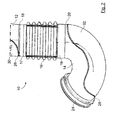
- Figure 1
- an isometric projection of an air duct of an internal combustion engine with two rigid duct parts which are connected by a pliable bellows;
- Figure 2
- another isometric projection of the air duct of
figure 1 ; - Figures 3 to 5
- a longitudinal section of an apparatus for manufacturing the air duct of
figures 1 and2 during different phases of a manufacturing process. - In the drawings, equal or similar elements are referred to by equal reference numerals. The drawings are merely schematic representations, not intended to portray specific parameters of the invention. Moreover, the drawings are intended to depict only typical embodiments of the invention and therefore should not be considered as limiting the scope of the invention.
-
Figures 1 and2 depict anair duct 10 of an internal combustion engine of a motor vehicle. - The
air duct 10 has tworigid duct parts rigid duct parts bellows 16 are made of different materials. Therigid duct parts ends connection rigid duct parts rigid duct part coupling flange - The
rigid duct parts rigid duct part opening cover opening 26 is for insertion and removing of anextruder 34 of anapparatus 38 for manufacturing theair duct 10. Theapparatus 38 is shown infigures 3 to 5 . Theopening 28 is for insertion and removing of a holdingmember 36 of theapparatus 38. Theopening 26 is aligned with the section forconnection 18 of the respectiverigid duct part 12. Theopening 28 is aligned with the section forconnection 20 of therigid duct part 14. The section forconnection 18 is coaxial to thebellows 16 at therespective end 17. The section forconnection 20 is coaxial to thebellows 16 at therespective end 19. - The
apparatus 38 will now be explained with the help offigures 3 to 5 . The holdingmember 36 has a cylindrical core. It can be inserted through theopening 28 into theair duct part 14. The holdingmember 36 holds the section forconnection 20. For the sake of clarity, infigure 3 to 5 only the sections forconnection air duct parts openings - The
extruder 34 has acylindrical extruder body 40. Theextruder body 40 can be inserted through theopening 26 into the rigidair duct part 12. Theextruder body 40 is movable relative to the holdingmember 36 inaxial direction 42 in the section forconnection 18 of the rigidair duct part 12. This is sketched out infigures 4 and 5 . Theextruder body 40 and the holdingmember 36 are coaxial. Theextruder body 40 and the holdingmember 36 can be mounted on a not shown framework of theapparatus 38. - The
extruder body 40 has anannular chamber 44 forplastic material 46. Theplastic material 46 is for realizing thebellows 16. From the chamber 44 a number ofchannels 48 lead to aface side 50 of theextruder body 14 which is facing the holdingmember 36. Thechannels 48 each end in anannular injector section 52 which opens to the border of the face side. Theinjector section 52 is directed at an angle both to radial outside of theextruder body 40 and to the holdingmember 36. In the chamber 44 aplunger 54 is arranged. Theplunger 54 is movable in axial direction to theextruder body 44 for pressing theplastic material 46 through thechannels 48. Thepressing direction 56 of theplunger 54 is sketched out infigures 4 and 5 . - An
inflation air channel 58 leads axial through theextruder body 40 and opens in theface side 60. With its other end theinflation air channel 58 is connected to a not shown air supplying device for supplying inflation air. - An
injection mold 60 for thebellows 16 surrounds theextruder body 40 and the holdingmember 36. Themold 60 has anopening 62 for the section forconnection 18 of the rigidair duct part 12 and anopening 64 for the section forconnection 20 of the rigidair duct part 14. The sections forconnection openings mold 60 can consist of two half shells. For fixing or releasing theconnections mold 60 realizes the form of thebellows 16. - For manufacturing the
air duct 10 therigid duct parts openings air duct parts injection mold 60 so that their sections forconnection respective opening injection mold 60 then holds therigid duct parts - The rigid
air duct part 14 is mounted on the holdingmember 36 whereby the latter being inserted through theopening 28. The holdingmember 36 is placed in the section forconnection 20 of the rigid atduct part 14. The holdingmember 36 then holds therigid duct parts - The
extruder body 40 is inserted into theinjection mold 60 through theopening 26 and the section forconnection 18 of the rigidair duct parts 12. In a starting position, which is shown infigure 3 , theface side 50 abuts against the respective face side of the holdingmember 36. The plunger 45 is in its starting position. The chamber forplastic 44 is filled with theplastic material 46. Theplastic material 46 melted by a not shown heater of theextruder 34. Theplunger 54 is started to move towards theface side 50 of theextruder body 40. Theplunger 54 presses the meltedplastic material 46 through thechannels 48 and theinjection section 52. Out of theinjection section 52 theplastic material 46 is extruded to an end of aparison 66. The meltedplastic material 46 which forms the end of theparison 66 is pressed throughclearance holes 68 of the section forconnection 20. Theparison 66 so is connected with its end to the section forconnection 20 by overmolding. - Then the
extruder body 14 is started to move away from the holdingmember 36 inaxial direction 42. This is shown infigure 4 . Simultaneously the plunger 45 this continued to move in pressingdirection 46. The meltedplastic material 46 is pressed continuously through theinjection section 52. Theparison 66 is extruded inaxial direction 42. When theinjection section 52 reaches the section forconnection 18 of therigid duct part 12 the movement of theextruder body 40 is stopped. This is shown infigure 5 . The movement of theplunger 52 is continued. The meltedplastic material 46 is pressed throughclearance holes 70 in the section forconnection 18. Theparison 66 so also is connected to the section forconnection 18 by overmolding. The movement of theplunger 54 is stopped. - Air is supplied by the air supplying device through the
inflation channel 58 into the interior of theparison 66. The stream of the inflating air is sketched out byarrows 72 with broken lines. Theparison 66 is inflated and pressed against the inner wall of theinjection mold 60. Thus theparison 66 is formed to thebellows 16. The inflatingair 72 and theinjection mold 60 cool down theplastic material 46 of thebellows 16. Theplastic material 46 solidifies. The connections between thebellows 16 and the sections forconnections - The
extruder body 40 is removed from the rigidair duct part 12 through theopening 26. Theair duct 10 and theinjection mold 60 are removed from the holdingmember 36. Theinjection mold 60 is removed from theair duct 10. Theopenings covers - The invention is not limited to an
air duct 10 of an internal combustion engine of a motor vehicle. The invention can also be applied for other kinds of line systems for fluids, particularly gases or liquids. The invention can further be applied to other kinds of internal combustion engines, in particular to industrial engines. - The
air duct 10 can also have less or more than tworigid duct parts - Instead of being bent one or both
rigid duct parts opening extruder 34 or the holdingmember 36. - Instead of a rigid plastic at least one of the two
rigid duct parts - At least one of the
rigid duct parts - The
rigid duct parts - The
air duct 10 can also have more than one bellows 16. - Instead of a flexible plastic the
bellows 16 can be made of another flexible material. - Instead of the
bellows 16 theair duct 10 can have another kind of duct part, in particular a pliable or a rigid duct part. - The embodiment of the
apparatus 38, in particular theextruder 34, the holdingmember 36 and theinjection mold 60, in thefigures 3 to 5 is only exemplary. It can vary for example dependent on the kind ofbellows 16 to be realized.
Claims (10)
- Line system for a fluid, in particular an air duct (10), in particular of an internal combustion engine, in particular of a motor vehicle, having at least one first duct part (12, 14) and at least one second duct part (16) made of different materials (46) which are connected to each other, characterized in that the at least one second duct part (16) is an extrusion blow molding article which is injection-molded to the at least one first duct part (12, 14).
- Line system according to claim 1, characterized in that the at least one second duct part (16) is pliable.
- Line system according to claim 1 or 2, characterized in that the at least one second duct part is a bellows (16).
- Line system according to one of the previous claims, characterized in that the at least one first duct part (12, 14) is rigid.
- Line system according to one of the previous claims, characterized in that the at least one second duct part (16) is connected with its ends (17, 19) each to a duct part (12, 14) which are made of different materials than the least one second duct part (16).
- Method of manufacturing a line system for a fluid, in particular an air duct (10), in particular of an internal combustion engine, in particular of a motor vehicle, wherein at least one first duct part (12, 14) is made of a first material and at least one second duct part (16) is made of a second material (46) and the at least one first duct part (12, 14) and the at least one second duct part (16) are connected to each other, characterized in that the second material (46) is extruded to a parison (66) and molded over a section for connection (18, 20) of the at least first duct part (12, 14), the parison (66) is inflated to form the at least one second duct part (16).
- Method according to claim 6, characterized in that the at least first duct part (12, 14) and an extruder (34) are placed in an injection mold (60) for the at least one second duct part (16), the second material (46) is extruded by the extruder (34) for overmolding the section for connection (20) of the at least first duct part (14), the extruder (34) is moved away from the at least first duct part (14) while extruding the second material (46) to the parison (66).
- Method according to claim 7, characterized in that the parison (66) is injected in the injection mold (60) by inflating.
- Apparatus (38) for manufacturing a line system for a fluid, in particular an air duct (10), in particular of an internal combustion engine, in particular of a motor vehicle, with a device (34, 36) for connecting at least one first duct part (12, 14) made of a first material with at least one second duct part (16) made of a second material (46), characterized in that the device contains a holding member (36) for holding the at least one first duct part (14), an extruder (36) for extruding the second material (46) to a parison (66) and molding the second material (46) over a section for connection (18, 20) of the at least first duct part (12, 14) and a member (58) for inflating the parison (66) to form the at least one second duct part (16).
- Apparatus according to claim 9, characterized in that the at least first duct part (12, 14) is placed in an injection mold (60) for the at least one second duct part (16) and the extruder (34) is placed movable relative to the holding member (36) in the injection mold (60).
Priority Applications (2)
| Application Number | Priority Date | Filing Date | Title |
|---|---|---|---|
| EP12290200.0A EP2677154B1 (en) | 2012-06-19 | 2012-06-19 | Line system for a fluid, method of manufacturing a line system and apparatus for manufacturing a line system |
| PCT/EP2013/062118 WO2013189799A1 (en) | 2012-06-19 | 2013-06-12 | Line system for a fluid, method of manufacturing a line system and apparatus for manufacturing a line system |
Applications Claiming Priority (1)
| Application Number | Priority Date | Filing Date | Title |
|---|---|---|---|
| EP12290200.0A EP2677154B1 (en) | 2012-06-19 | 2012-06-19 | Line system for a fluid, method of manufacturing a line system and apparatus for manufacturing a line system |
Publications (2)
| Publication Number | Publication Date |
|---|---|
| EP2677154A1 true EP2677154A1 (en) | 2013-12-25 |
| EP2677154B1 EP2677154B1 (en) | 2018-11-28 |
Family
ID=48579123
Family Applications (1)
| Application Number | Title | Priority Date | Filing Date |
|---|---|---|---|
| EP12290200.0A Active EP2677154B1 (en) | 2012-06-19 | 2012-06-19 | Line system for a fluid, method of manufacturing a line system and apparatus for manufacturing a line system |
Country Status (2)
| Country | Link |
|---|---|
| EP (1) | EP2677154B1 (en) |
| WO (1) | WO2013189799A1 (en) |
Cited By (1)
| Publication number | Priority date | Publication date | Assignee | Title |
|---|---|---|---|---|
| KR20200128436A (en) * | 2018-04-27 | 2020-11-12 | 말레 인터내셔널 게엠베하 | Tubular body for fresh air systems in internal combustion engines |
Citations (4)
| Publication number | Priority date | Publication date | Assignee | Title |
|---|---|---|---|---|
| US5806480A (en) * | 1996-09-04 | 1998-09-15 | Toyoda Gosei Co., Inc. | Air intake system |
| EP0913242A1 (en) * | 1997-10-30 | 1999-05-06 | Steere Enterprises, Inc. | Clean air ducts and methods for the manufacture therof |
| US20060125149A1 (en) * | 2003-08-19 | 2006-06-15 | Seiichiro Takada | Method for forming duct made of elastomer |
| US20110316195A1 (en) * | 2010-06-25 | 2011-12-29 | Kia Motors Corporation | Injection mold for intake hose and intake hose production method using the same |
-
2012
- 2012-06-19 EP EP12290200.0A patent/EP2677154B1/en active Active
-
2013
- 2013-06-12 WO PCT/EP2013/062118 patent/WO2013189799A1/en active Application Filing
Patent Citations (4)
| Publication number | Priority date | Publication date | Assignee | Title |
|---|---|---|---|---|
| US5806480A (en) * | 1996-09-04 | 1998-09-15 | Toyoda Gosei Co., Inc. | Air intake system |
| EP0913242A1 (en) * | 1997-10-30 | 1999-05-06 | Steere Enterprises, Inc. | Clean air ducts and methods for the manufacture therof |
| US20060125149A1 (en) * | 2003-08-19 | 2006-06-15 | Seiichiro Takada | Method for forming duct made of elastomer |
| US20110316195A1 (en) * | 2010-06-25 | 2011-12-29 | Kia Motors Corporation | Injection mold for intake hose and intake hose production method using the same |
Cited By (3)
| Publication number | Priority date | Publication date | Assignee | Title |
|---|---|---|---|---|
| KR20200128436A (en) * | 2018-04-27 | 2020-11-12 | 말레 인터내셔널 게엠베하 | Tubular body for fresh air systems in internal combustion engines |
| KR102253979B1 (en) | 2018-04-27 | 2021-05-21 | 말레 인터내셔널 게엠베하 | Tubular body for fresh air systems in internal combustion engines |
| EP3784897B1 (en) * | 2018-04-27 | 2022-06-22 | Mahle International GmbH | Pipe duct for intake air system of an internal combustion engine |
Also Published As
| Publication number | Publication date |
|---|---|
| WO2013189799A1 (en) | 2013-12-27 |
| EP2677154B1 (en) | 2018-11-28 |
Similar Documents
| Publication | Publication Date | Title |
|---|---|---|
| CN102958677B (en) | Method for the riveted fastening of an accessory | |
| ES2321207T3 (en) | METHOD TO CONFORM AS A CAP THE END OF A THERMOPLASTIC MATERIAL TUBE, IN PARTICULAR OF A POLYOLEFINIC MATERIAL, AND PRESSURE FLUID TUBE. | |
| EP2677154B1 (en) | Line system for a fluid, method of manufacturing a line system and apparatus for manufacturing a line system | |
| FI112337B (en) | A method of making a plastic tube | |
| JP5019005B1 (en) | Resin tube folding method, resin tube coating roll manufacturing method | |
| CN103711622B (en) | For the pipe-line system of fluid, the method and apparatus of at least one tube portion for connecting pipe system | |
| CN107538722B (en) | Blow molding apparatus and method for manufacturing blow molded container | |
| JP4420279B2 (en) | Plastic Constant Velocity Joint Boot Manufacturing Equipment Plastic Constant Velocity Joint Boot Manufacturing Method Resin Constant Velocity Joint Boot | |
| JP4424137B2 (en) | Manufacturing method of tube resin joint | |
| US8282867B2 (en) | Insert molding die, insert molding apparatus and insert molding method | |
| JP2000334818A (en) | Molding, blow molding machine for molding. and its molding method | |
| CN217319020U (en) | Injection mold capable of accelerating cooling and demolding of injection product | |
| CN219114746U (en) | Pyrocondensation pipe forming die and extruder | |
| JP4291325B2 (en) | Manufacturing method of resin joint boots | |
| EP2679797A1 (en) | Duct part of the pipe system for a fluid, method and apparatus for manufacturing a duct part of a pipe system | |
| JP7451856B2 (en) | Method for manufacturing a resin pipe with a fixing member and apparatus for manufacturing a resin pipe with a fixing member | |
| JP7451590B2 (en) | Method and apparatus for manufacturing a device for transporting media | |
| EP2884087A1 (en) | Duct system | |
| JPH10272679A (en) | Die structure for injection blow molding | |
| JP2686545B2 (en) | Method of manufacturing bent hose with protector | |
| KR100520920B1 (en) | a | |
| JP4011763B2 (en) | Hose flange forming method | |
| JP2016043675A (en) | Production method of bellows, and bellows | |
| JP2005081825A (en) | Method for forming formed elastomer article | |
| EP2788165A2 (en) | A manufacturing method for bellow pipes |
Legal Events
| Date | Code | Title | Description |
|---|---|---|---|
| PUAI | Public reference made under article 153(3) epc to a published international application that has entered the european phase |
Free format text: ORIGINAL CODE: 0009012 |
|
| AK | Designated contracting states |
Kind code of ref document: A1 Designated state(s): AL AT BE BG CH CY CZ DE DK EE ES FI FR GB GR HR HU IE IS IT LI LT LU LV MC MK MT NL NO PL PT RO RS SE SI SK SM TR |
|
| AX | Request for extension of the european patent |
Extension state: BA ME |
|
| 17P | Request for examination filed |
Effective date: 20140320 |
|
| RBV | Designated contracting states (corrected) |
Designated state(s): AL AT BE BG CH CY CZ DE DK EE ES FI FR GB GR HR HU IE IS IT LI LT LU LV MC MK MT NL NO PL PT RO RS SE SI SK SM TR |
|
| 17Q | First examination report despatched |
Effective date: 20160520 |
|
| GRAP | Despatch of communication of intention to grant a patent |
Free format text: ORIGINAL CODE: EPIDOSNIGR1 |
|
| STAA | Information on the status of an ep patent application or granted ep patent |
Free format text: STATUS: GRANT OF PATENT IS INTENDED |
|
| INTG | Intention to grant announced |
Effective date: 20180619 |
|
| GRAS | Grant fee paid |
Free format text: ORIGINAL CODE: EPIDOSNIGR3 |
|
| GRAA | (expected) grant |
Free format text: ORIGINAL CODE: 0009210 |
|
| STAA | Information on the status of an ep patent application or granted ep patent |
Free format text: STATUS: THE PATENT HAS BEEN GRANTED |
|
| RAP1 | Party data changed (applicant data changed or rights of an application transferred) |
Owner name: MANN+HUMMEL GMBH |
|
| AK | Designated contracting states |
Kind code of ref document: B1 Designated state(s): AL AT BE BG CH CY CZ DE DK EE ES FI FR GB GR HR HU IE IS IT LI LT LU LV MC MK MT NL NO PL PT RO RS SE SI SK SM TR |
|
| REG | Reference to a national code |
Ref country code: GB Ref legal event code: FG4D |
|
| REG | Reference to a national code |
Ref country code: CH Ref legal event code: EP |
|
| REG | Reference to a national code |
Ref country code: AT Ref legal event code: REF Ref document number: 1070544 Country of ref document: AT Kind code of ref document: T Effective date: 20181215 |
|
| REG | Reference to a national code |
Ref country code: DE Ref legal event code: R096 Ref document number: 602012054018 Country of ref document: DE |
|
| REG | Reference to a national code |
Ref country code: IE Ref legal event code: FG4D |
|
| REG | Reference to a national code |
Ref country code: NL Ref legal event code: MP Effective date: 20181128 |
|
| REG | Reference to a national code |
Ref country code: LT Ref legal event code: MG4D |
|
| REG | Reference to a national code |
Ref country code: AT Ref legal event code: MK05 Ref document number: 1070544 Country of ref document: AT Kind code of ref document: T Effective date: 20181128 |
|
| PG25 | Lapsed in a contracting state [announced via postgrant information from national office to epo] |
Ref country code: ES Free format text: LAPSE BECAUSE OF FAILURE TO SUBMIT A TRANSLATION OF THE DESCRIPTION OR TO PAY THE FEE WITHIN THE PRESCRIBED TIME-LIMIT Effective date: 20181128 Ref country code: HR Free format text: LAPSE BECAUSE OF FAILURE TO SUBMIT A TRANSLATION OF THE DESCRIPTION OR TO PAY THE FEE WITHIN THE PRESCRIBED TIME-LIMIT Effective date: 20181128 Ref country code: LV Free format text: LAPSE BECAUSE OF FAILURE TO SUBMIT A TRANSLATION OF THE DESCRIPTION OR TO PAY THE FEE WITHIN THE PRESCRIBED TIME-LIMIT Effective date: 20181128 Ref country code: IS Free format text: LAPSE BECAUSE OF FAILURE TO SUBMIT A TRANSLATION OF THE DESCRIPTION OR TO PAY THE FEE WITHIN THE PRESCRIBED TIME-LIMIT Effective date: 20190328 Ref country code: FI Free format text: LAPSE BECAUSE OF FAILURE TO SUBMIT A TRANSLATION OF THE DESCRIPTION OR TO PAY THE FEE WITHIN THE PRESCRIBED TIME-LIMIT Effective date: 20181128 Ref country code: BG Free format text: LAPSE BECAUSE OF FAILURE TO SUBMIT A TRANSLATION OF THE DESCRIPTION OR TO PAY THE FEE WITHIN THE PRESCRIBED TIME-LIMIT Effective date: 20190228 Ref country code: LT Free format text: LAPSE BECAUSE OF FAILURE TO SUBMIT A TRANSLATION OF THE DESCRIPTION OR TO PAY THE FEE WITHIN THE PRESCRIBED TIME-LIMIT Effective date: 20181128 Ref country code: AT Free format text: LAPSE BECAUSE OF FAILURE TO SUBMIT A TRANSLATION OF THE DESCRIPTION OR TO PAY THE FEE WITHIN THE PRESCRIBED TIME-LIMIT Effective date: 20181128 Ref country code: NO Free format text: LAPSE BECAUSE OF FAILURE TO SUBMIT A TRANSLATION OF THE DESCRIPTION OR TO PAY THE FEE WITHIN THE PRESCRIBED TIME-LIMIT Effective date: 20190228 |
|
| PG25 | Lapsed in a contracting state [announced via postgrant information from national office to epo] |
Ref country code: RS Free format text: LAPSE BECAUSE OF FAILURE TO SUBMIT A TRANSLATION OF THE DESCRIPTION OR TO PAY THE FEE WITHIN THE PRESCRIBED TIME-LIMIT Effective date: 20181128 Ref country code: PT Free format text: LAPSE BECAUSE OF FAILURE TO SUBMIT A TRANSLATION OF THE DESCRIPTION OR TO PAY THE FEE WITHIN THE PRESCRIBED TIME-LIMIT Effective date: 20190328 Ref country code: GR Free format text: LAPSE BECAUSE OF FAILURE TO SUBMIT A TRANSLATION OF THE DESCRIPTION OR TO PAY THE FEE WITHIN THE PRESCRIBED TIME-LIMIT Effective date: 20190301 Ref country code: AL Free format text: LAPSE BECAUSE OF FAILURE TO SUBMIT A TRANSLATION OF THE DESCRIPTION OR TO PAY THE FEE WITHIN THE PRESCRIBED TIME-LIMIT Effective date: 20181128 Ref country code: SE Free format text: LAPSE BECAUSE OF FAILURE TO SUBMIT A TRANSLATION OF THE DESCRIPTION OR TO PAY THE FEE WITHIN THE PRESCRIBED TIME-LIMIT Effective date: 20181128 |
|
| PG25 | Lapsed in a contracting state [announced via postgrant information from national office to epo] |
Ref country code: NL Free format text: LAPSE BECAUSE OF FAILURE TO SUBMIT A TRANSLATION OF THE DESCRIPTION OR TO PAY THE FEE WITHIN THE PRESCRIBED TIME-LIMIT Effective date: 20181128 |
|
| PG25 | Lapsed in a contracting state [announced via postgrant information from national office to epo] |
Ref country code: DK Free format text: LAPSE BECAUSE OF FAILURE TO SUBMIT A TRANSLATION OF THE DESCRIPTION OR TO PAY THE FEE WITHIN THE PRESCRIBED TIME-LIMIT Effective date: 20181128 Ref country code: CZ Free format text: LAPSE BECAUSE OF FAILURE TO SUBMIT A TRANSLATION OF THE DESCRIPTION OR TO PAY THE FEE WITHIN THE PRESCRIBED TIME-LIMIT Effective date: 20181128 Ref country code: IT Free format text: LAPSE BECAUSE OF FAILURE TO SUBMIT A TRANSLATION OF THE DESCRIPTION OR TO PAY THE FEE WITHIN THE PRESCRIBED TIME-LIMIT Effective date: 20181128 Ref country code: PL Free format text: LAPSE BECAUSE OF FAILURE TO SUBMIT A TRANSLATION OF THE DESCRIPTION OR TO PAY THE FEE WITHIN THE PRESCRIBED TIME-LIMIT Effective date: 20181128 |
|
| REG | Reference to a national code |
Ref country code: DE Ref legal event code: R097 Ref document number: 602012054018 Country of ref document: DE |
|
| PG25 | Lapsed in a contracting state [announced via postgrant information from national office to epo] |
Ref country code: SK Free format text: LAPSE BECAUSE OF FAILURE TO SUBMIT A TRANSLATION OF THE DESCRIPTION OR TO PAY THE FEE WITHIN THE PRESCRIBED TIME-LIMIT Effective date: 20181128 Ref country code: SM Free format text: LAPSE BECAUSE OF FAILURE TO SUBMIT A TRANSLATION OF THE DESCRIPTION OR TO PAY THE FEE WITHIN THE PRESCRIBED TIME-LIMIT Effective date: 20181128 Ref country code: EE Free format text: LAPSE BECAUSE OF FAILURE TO SUBMIT A TRANSLATION OF THE DESCRIPTION OR TO PAY THE FEE WITHIN THE PRESCRIBED TIME-LIMIT Effective date: 20181128 Ref country code: RO Free format text: LAPSE BECAUSE OF FAILURE TO SUBMIT A TRANSLATION OF THE DESCRIPTION OR TO PAY THE FEE WITHIN THE PRESCRIBED TIME-LIMIT Effective date: 20181128 |
|
| PLBE | No opposition filed within time limit |
Free format text: ORIGINAL CODE: 0009261 |
|
| STAA | Information on the status of an ep patent application or granted ep patent |
Free format text: STATUS: NO OPPOSITION FILED WITHIN TIME LIMIT |
|
| PG25 | Lapsed in a contracting state [announced via postgrant information from national office to epo] |
Ref country code: SI Free format text: LAPSE BECAUSE OF FAILURE TO SUBMIT A TRANSLATION OF THE DESCRIPTION OR TO PAY THE FEE WITHIN THE PRESCRIBED TIME-LIMIT Effective date: 20181128 |
|
| 26N | No opposition filed |
Effective date: 20190829 |
|
| PG25 | Lapsed in a contracting state [announced via postgrant information from national office to epo] |
Ref country code: MC Free format text: LAPSE BECAUSE OF FAILURE TO SUBMIT A TRANSLATION OF THE DESCRIPTION OR TO PAY THE FEE WITHIN THE PRESCRIBED TIME-LIMIT Effective date: 20181128 |
|
| REG | Reference to a national code |
Ref country code: CH Ref legal event code: PL |
|
| GBPC | Gb: european patent ceased through non-payment of renewal fee |
Effective date: 20190619 |
|
| REG | Reference to a national code |
Ref country code: BE Ref legal event code: MM Effective date: 20190630 |
|
| PG25 | Lapsed in a contracting state [announced via postgrant information from national office to epo] |
Ref country code: TR Free format text: LAPSE BECAUSE OF FAILURE TO SUBMIT A TRANSLATION OF THE DESCRIPTION OR TO PAY THE FEE WITHIN THE PRESCRIBED TIME-LIMIT Effective date: 20181128 |
|
| PG25 | Lapsed in a contracting state [announced via postgrant information from national office to epo] |
Ref country code: GB Free format text: LAPSE BECAUSE OF NON-PAYMENT OF DUE FEES Effective date: 20190619 Ref country code: IE Free format text: LAPSE BECAUSE OF NON-PAYMENT OF DUE FEES Effective date: 20190619 |
|
| PG25 | Lapsed in a contracting state [announced via postgrant information from national office to epo] |
Ref country code: LI Free format text: LAPSE BECAUSE OF NON-PAYMENT OF DUE FEES Effective date: 20190630 Ref country code: LU Free format text: LAPSE BECAUSE OF NON-PAYMENT OF DUE FEES Effective date: 20190619 Ref country code: BE Free format text: LAPSE BECAUSE OF NON-PAYMENT OF DUE FEES Effective date: 20190630 Ref country code: CH Free format text: LAPSE BECAUSE OF NON-PAYMENT OF DUE FEES Effective date: 20190630 |
|
| PG25 | Lapsed in a contracting state [announced via postgrant information from national office to epo] |
Ref country code: CY Free format text: LAPSE BECAUSE OF FAILURE TO SUBMIT A TRANSLATION OF THE DESCRIPTION OR TO PAY THE FEE WITHIN THE PRESCRIBED TIME-LIMIT Effective date: 20181128 |
|
| PG25 | Lapsed in a contracting state [announced via postgrant information from national office to epo] |
Ref country code: MT Free format text: LAPSE BECAUSE OF FAILURE TO SUBMIT A TRANSLATION OF THE DESCRIPTION OR TO PAY THE FEE WITHIN THE PRESCRIBED TIME-LIMIT Effective date: 20181128 Ref country code: HU Free format text: LAPSE BECAUSE OF FAILURE TO SUBMIT A TRANSLATION OF THE DESCRIPTION OR TO PAY THE FEE WITHIN THE PRESCRIBED TIME-LIMIT; INVALID AB INITIO Effective date: 20120619 |
|
| PG25 | Lapsed in a contracting state [announced via postgrant information from national office to epo] |
Ref country code: MK Free format text: LAPSE BECAUSE OF FAILURE TO SUBMIT A TRANSLATION OF THE DESCRIPTION OR TO PAY THE FEE WITHIN THE PRESCRIBED TIME-LIMIT Effective date: 20181128 |
|
| PGFP | Annual fee paid to national office [announced via postgrant information from national office to epo] |
Ref country code: FR Payment date: 20230627 Year of fee payment: 12 Ref country code: DE Payment date: 20230620 Year of fee payment: 12 |