EP2676916A1 - Overhead transport vehicle - Google Patents
Overhead transport vehicle Download PDFInfo
- Publication number
- EP2676916A1 EP2676916A1 EP11858523.1A EP11858523A EP2676916A1 EP 2676916 A1 EP2676916 A1 EP 2676916A1 EP 11858523 A EP11858523 A EP 11858523A EP 2676916 A1 EP2676916 A1 EP 2676916A1
- Authority
- EP
- European Patent Office
- Prior art keywords
- pushing
- lever
- article
- lever member
- end side
- Prior art date
- Legal status (The legal status is an assumption and is not a legal conclusion. Google has not performed a legal analysis and makes no representation as to the accuracy of the status listed.)
- Granted
Links
Images





Classifications
-
- B—PERFORMING OPERATIONS; TRANSPORTING
- B66—HOISTING; LIFTING; HAULING
- B66C—CRANES; LOAD-ENGAGING ELEMENTS OR DEVICES FOR CRANES, CAPSTANS, WINCHES, OR TACKLES
- B66C13/00—Other constructional features or details
- B66C13/04—Auxiliary devices for controlling movements of suspended loads, or preventing cable slack
- B66C13/06—Auxiliary devices for controlling movements of suspended loads, or preventing cable slack for minimising or preventing longitudinal or transverse swinging of loads
-
- B—PERFORMING OPERATIONS; TRANSPORTING
- B61—RAILWAYS
- B61B—RAILWAY SYSTEMS; EQUIPMENT THEREFOR NOT OTHERWISE PROVIDED FOR
- B61B3/00—Elevated railway systems with suspended vehicles
-
- H—ELECTRICITY
- H10—SEMICONDUCTOR DEVICES; ELECTRIC SOLID-STATE DEVICES NOT OTHERWISE PROVIDED FOR
- H10P—GENERIC PROCESSES OR APPARATUS FOR THE MANUFACTURE OR TREATMENT OF DEVICES COVERED BY CLASS H10
- H10P72/00—Handling or holding of wafers, substrates or devices during manufacture or treatment thereof
- H10P72/30—Handling or holding of wafers, substrates or devices during manufacture or treatment thereof for conveying, e.g. between different workstations
- H10P72/32—Handling or holding of wafers, substrates or devices during manufacture or treatment thereof for conveying, e.g. between different workstations between different workstations
- H10P72/3221—Overhead conveying
Definitions
- This invention relates to an overhead transport vehicle, particularly to an overhead transport vehicle that conveys an article such as a container, etc. that contains various kinds of substrates and etc. for manufacturing a semiconductor equipment on a rail.
- An overhead hoist vehicle (so-called OHT: Overhead Hoist Transport) is known as a conventional conveying vehicle.
- the overhead hoist vehicle conveys an article such as a FOUP (Front Opening Unified Pod) and etc. by travelling on a rail arranged on a ceiling.
- Such conveying vehicle may comprise a falling prevention member and a swing inhibiting member.
- the falling prevention member is configured to prevent the article from falling, by projecting under the transferred article.
- the swing inhibiting member is configured to rotate in conjunction with a movement of the falling prevention member and is configured to inhibit swing by pushing the article.
- patent citation 1 discloses a mechanism that pushes an elastic body such as a gel and etc. with a linear movement mechanism, the linear movement mechanism working with the falling prevention member.
- patent citation 2 discloses a mechanism in which a pushing member is directly attached to the falling prevention member.
- This invention is carried out in light of the above-described problem, and the problem to be solved is to provide a conveying vehicle and a conveying system that can effectively reduce the transmission of the swing and vibrations to the article.
- a conveying vehicle comprises a travelling unit, a conveying unit, and a swing inhibiting member.
- the travelling unit is configured to travel on a rail arranged on or near a ceiling.
- the conveying unit is attached to the travelling unit, and configured to both move an article into a containing space and convey the article.
- the swing inhibiting member is pivotally supported by the conveying unit.
- the swing inhibiting member is configured to move between a pushing position, and a retracting position.
- the pushing position is a position from which a side surface of the article is pushed.
- the retracting position is a position away from the pushing position enabling the swing inhibiting member to move the article into the containing space.
- the swing inhibiting member includes a pushing member, a lever member, and a biasing member.
- the pushing member is configured to push the side surface of the article.
- a first end side of the lever member is configured to support the pushing member.
- a second end side of the lever member is pivotally supported by the conveying unit.
- the biasing member is arranged in the lever member, and is configured to bias the pushing member to the article.
- the pushing member includes a main body member, a slide member, and elastic bodies.
- the main body member is pivotally supported by the lever member.
- the slide member includes a pushing surface to be abutted the article.
- the slide member is supported by the main body member so as to slide in a direction crossing a travelling direction of the conveying vehicle (a slide direction).
- the elastic bodies are configured to elastically slide the slide member.
- the elastic bodies are arranged between the main body member and the slide member.
- the conveying vehicle comprises the travelling unit, configured to travel on the rail arranged on or near the ceiling, and the conveying unit, which is attached to the travelling unit.
- the conveying unit is configured to move the article into a containing space
- the travelling unit is configured to travel on the rail, thus the article is conveyed.
- the conveying unit is typically attached to the travelling unit, and suspended from the travelling unit.
- the conveying unit includes a gripping member configured to grip the article, for example. When the conveying unit carries the article, the article gripped by the gripping member is moved into the containing space.
- the containing space is defined as an U-shaped inner space that is opened downwardly, for example.
- the conveying vehicle comprises the swing inhibiting member.
- the swing inhibiting member is supported by the conveying unit. Specifically, the swing inhibiting member is supported by a lower end side of the conveying unit so as to rotate in a horizontal direction.
- the lower end side described here means a position low enough to push the article carried in the containing space from the side.
- the horizontal direction means not only the direction completely horizontal but also covers a broader meaning such as a direction obliquely crossing the horizontal direction.
- the swing inhibiting member is configured to move between the pushing position and the retracting position. Specifically, this swing inhibiting member is configured to move from the pushing position to the retracting position, and vice versa, by rotating in the horizontal direction. More specifically, when the article is about to be carried, the swing inhibiting member is in a state where at least part of the swing inhibiting member is retracted so as to make enough space for the article to pass the space in the vicinity of an entrance of the containing space. On the other hand, after carrying the article, the swing inhibiting member is configured to push the side surface of the article by projecting to the side of the containing space (namely, the side of the article contained), thus preventing the article from swinging.
- “swing” described here means a larger swing that is generated by a centrifugal force generated when the article, that is transported on the conveying vehicle, travels on a curve.
- the swing inhibiting member includes a pushing member, a lever member, and a biasing member.
- the pushing member is configured to push the side surface of the article.
- the pushing member is configured to push, in a planar manner, the side surface of the article when the pushing member is at the pushing position.
- the lever member is configured to support the pushing member at the first end side.
- the second end side of the lever member is pivotally supported by the conveying unit.
- the biasing member is arranged in the lever member, and configured to bias the pushing member to the side of the article.
- the lever member is pivotally supported by the conveying unit.
- the pushing member abuts the side surface of the article due to the rotation of the lever member pivotally supported by the conveying member.
- the pushing member abuts the side surface of the article due to a linear movement of the swing inhibiting member.
- a large space in a travelling direction is required to arrange a linear movement mechanism. Therefore, in such a structure, equipment may become larger, and the space for arranging other members may be reduced.
- the swing inhibiting member according to the present invention allows the pushing member to abut the side surface of the article by the rotation of the lever member. As a result, the swing inhibiting member can preferably be retracted within an extremely small space. Therefore, downsizing of an equipment can be realized.
- the pushing member according to the present invention pushes the side surface of the article, the swing can reliably be inhibited even if the article swings in the direction crossing the pushing direction.
- the pushing member is configured to push the side surface of the article in a planar manner, and when the article swings in the direction crossing the pushing direction, the swing can reliably be inhibited.
- the pushing member is configured to push the article, not only with the rotating force to the lever member, but also with the biasing force by the biasing member. With such a structure, since the pushing member can push the article while following the swing of the article, the swing of the article can be inhibited very effectively.
- the above-described pushing member includes the above-described main body member, the above-described slide member, and the above-described elastic bodies.
- the slide member is supported by the main body member in a manner such that it can slide in the slide direction.
- the main body member pivotally supported by the lever member, enables an angle of a pushing surface to change, in accordance with an angle of the article, in the containing space. Therefore, the side surface of the article can be reliably pushed by the pushing surface.
- the slide member slidably supported by the main body member, is able to absorb vibrations transmitted from the conveying vehicle, and to prevent transmission of the vibrations to the article.
- vibration described here means smaller swing generated in a travelling system of the conveying vehicle.
- the slide member is further configured to slide elastically by the elastic bodies. Therefore, the transmission of the vibrations to the article can reliably be inhibited.
- the main body member in the pushing member, is formed in a block shape.
- the main body member includes a planar projecting plate portion projecting away from the pushing surface.
- the slide member includes a first and second longitudinal members, a lateral member, and a shaft member.
- the first and second longitudinal members are provided to the pushing surface and at both sides of the main body member with predetermined gaps from the main body member, respectively.
- the lateral member connects the first and second longitudinal members with each other, and is configured to support the projecting plate portion.
- the lateral member is configured to slide the projecting plate portion in the slide direction, and to avoid moving the projecting plate portion upward and downward.
- the shaft member is inserted into a through hole formed in the main body member.
- the shaft member is configured to slide relative to the main body member, and to connect the first and second longitudinal members with each other at a place between the pushing surface and the lateral member.
- the elastic bodies are arranged in the predetermined gap between the main body member and the first longitudinal member, and are disposed in the predetermined gap between the main body member and the second longitudinal member.
- the main body member is formed in a block shape, and configured to include the planar projecting plate portion.
- the projecting plate portion is supported by the lateral member of the slide member so as to slide in the slide direction, and so as to not move upward and downward.
- the first and second longitudinal members are arranged at both sides of the main body member with the predetermined gaps from the main body member, respectively, as the first and second longitudinal members project, from both sides in a width direction of the pushing surface (namely, both ends of the side), to the main body member.
- the lateral member is arranged so as to connect the first and second longitudinal members with each other at the edge.
- a pair of elastic bodies are arranged in the predetermined gap between the main body member and the first longitudinal member, and in the predetermined gap between the main body member and the second longitudinal member.
- the predetermined gap according to this aspect is arranged so that the gap is large enough to arrange a pair of the elastic bodies.
- a pair of the elastic bodies enables both the sliding to the first longitudinal member of the main body member, and the sliding to the second longitudinal member, to be preferably elastic sliding movements. Therefore, the transmission of vibrations to the article can effectively be inhibited.
- the lever member has a first lever member and a second lever member.
- a first end side of the first lever member is pivotally supported by the transport vehicle.
- a first end side of the second lever member is pivotally supported by a second end side of the first lever member.
- a second end side of the second lever member is configured to pivotally support the pushing member.
- the biasing member is arranged at a place where the first lever member and the second lever member are connected with each other.
- the biasing member is configured to bias the second lever member so as to align the first lever member and the second lever member in line.
- the lever member further includes a driving force transmitting means configured to transmit a rotating force that rotates the first lever member to the article.
- a base end side (the first end side) of the first lever member is pivotally supported by the conveying unit.
- a base end side (the first end side) of the second lever member is pivotally supported by a tip side (the second end side) of the first lever member.
- the pushing member is attached to a tip side (the second end side) of the second lever member.
- the biasing member is arranged at the place where the first lever member and the second lever member are connected with each other.
- the biasing member is formed, for example, as a torsional spring. This biasing member is configured to bias the second lever member so as to align the first lever member and the second lever member in line.
- the driving force transmitting means first transmits the rotating force to the first lever member, and then the first lever member and the second lever member rotate relative to the conveying unit. This allows the pushing member to abut the article. After the pushing member abuts the article, the first lever member continues rotating in the same manner.
- the second lever member is dogleg, relative to the first lever member, and the biasing force from the biasing member is applied to the first lever member and the second lever member.
- the conveying vehicle further comprises a falling prevention member.
- the falling prevention member is pivotally supported by the conveying unit under the swing inhibiting member so as to rotate.
- the falling prevention member is configured to project under the article in conjunction with a movement of the swing inhibiting member, from the retraction position to the pushing position, and prevent the article from falling from the containing space.
- the driving force transmitting means includes a projecting unit and a force receiving guide.
- the projecting unit is arranged to the falling prevention member.
- the force receiving guide is arranged to the first lever member and configured to receive a force from the projecting unit.
- the falling prevention member can prevent the article contained in the containing space from falling. Specifically, the falling prevention member moves to project under the article and works in conjunction with the movement of the swing inhibiting member moving from the retracting position to the pushing position. Thus, for example, it is possible to receive an article that is about to fall from the containing space, due to the swing of the conveying vehicle from the lower side of the containing space.
- the projecting unit as the driving force transmitting means is specially arranged to work with the above-described falling prevention member.
- the force receiving guide as the driving force transmitting means is arranged to work with the first lever member of the swing inhibiting member. The force receiving guide is configured to convert the force received from the projecting unit, to the rotating force of the first lever member. Therefore, it is possible to couple the falling prevention member to the swing inhibiting member, and move the falling prevention member and the swing inhibiting member with an extremely simple structure.
- the lever member includes the first lever member and the second lever member
- the biasing member prefferably be a torsional spring.
- the torsional spring is attached to the first lever member at the first end side and is attached to the second lever member at the second end side.
- the torsional spring since the first end side of the torsional spring is attached to the first lever member, and the second end side of the torsional spring is attached to the second lever member, it is possible to reliably generate the biasing force with which the first lever member and the second lever member utilize to align in line.
- the torsional spring since the torsional spring is low in cost and simple in structure, it is possible to avoid increasing the manufacturing cost and making the structure of the equipment complicated.
- the biasing member is a torsional spring
- the first end side of the torsional spring to abut the first lever member via a buffering member
- the second end side of the torsional spring to abut the second lever member, via a buffering member
- the buffering members are arranged between the torsional spring as the biasing member and the first lever member, and between the torsional spring and the second lever member. With such a buffering member, it is possible to extremely rapidly damp the swing, of the article pushed by the swing inhibiting member, in a biasing direction of the spring.
- the biasing member prefferably be a plate spring.
- the plate spring is configured to abut the first lever member at the first end side. and configured to abut the second lever member at the second end side.
- the plate spring since the first end side of the plate spring abut the first lever member, and the second end side of the plate spring abuts the second lever member, it is possible to reliably generate the biasing force with which the first lever member and the second lever member utilize to align in line.
- the plate spring since the plate spring is low in cost and simple in structure, it is possible to avoid increasing the manufacturing cost and complicatinging the structure of the equipment.
- the biasing member is a plate spring, for the first end side of the plate spring to abut the first lever member via a buffering member, and for the second end side of the plate spring to abut the second lever member, via a buffering member.
- the buffering members are arranged between the plate spring as the biasing member and the first lever member, and between the plate spring and the second lever member. With such a buffering member, it is possible to extremely rapidly damp the swing, of the article pushed by the swing inhibiting member, in a biasing direction of the spring.
- the pushing member includes an elastic body arranged on at least one part of the pushing surface.
- the elastic body is arranged on at least one part of the pushing surface abutting the article.
- This elastic body is different from the elastic body that enables the slide member to slide elastically. With this elastic body, since it is possible to push elastically the article, it is possible to avoid scratches on, and damage to, the article. In addition, it is possible to reliably damp the swing of the conveyed vehicle, and to inhibit the transmission of the vibration of the article.
- the other elastic body is arranged so as to cover the entire pushing surface.
- other elastic body is arranged to the part other than the pushing surface. Additional effects and merits of the invention will be clarified in the description of the embodiments that follow.
- the conveying system according to the present invention comprises a vehicle as one example of "an overhead transport vehicle”.
- Fig. 1 is a top view showing the overall structure of the conveying system.
- the conveying system comprises a rail 100, vehicles 200, and a controller 300.
- the rail 100 is arranged, for example, on a ceiling and made of metals such as aluminium, stainless steel, and etc.
- a plurality of the vehicles 200 are arranged on the rail 100.
- Each vehicle 200 can convey a FOUP as an article by travelling along the rail 100.
- each vehicle 200 has an onboard controller 205.
- the onboard controller 205 receives a conveying instruction from a controller 300 and controls the travelling of the vehicle 200. It should be noted that the onboard controller 205 controls not only the travelling of the vehicle 200 but also overall equipments included in the vehicle 200.
- the controller 300 includes, for example, an arithmetic circuit, a memory, and etc.
- the controller 300 is configured to provide the conveying instruction to the vehicle 200 via the onboard controller 205.
- a shelf that stores temporarily a FOUP (for example, a buffer, a port, and etc.) and a semiconductor manufacturing equipment are arranged along the rail 100.
- Fig. 2 is a side view showing the structure of the vehicle.
- the vehicle 200 includes travelling units 210, a main body member 220, a moving unit 230, a hoisting unit 235, a gripping unit 250, a falling prevention member 260, and a swing inhibiting member 270.
- travelling rollers 215 roll and the vehicle 200 travels along the rail 100.
- the main body member 220 as one example of "a conveying unit" of the present invention is suspended.
- the moving unit 230 is attached to the main body member 220.
- the moving unit 230 can move to the sides of the rail 100 (namely, a vertical direction to the surface of paper in Fig. 2 ).
- the hoisting unit 235 is attached on the lower surface of the moving unit 230.
- the gripping unit 250 configured to grip the FOUP is attached by a hoisting belt 240.
- the gripping unit 250 can descend or ascend by winding off the hoisting belt 240 or reeling the hoisting belt 240.
- the falling prevention members 260 are arranged in the vicinity of a lower end of the main body member 220.
- the falling prevention members 260 are configured to prevent the FOUP from falling by projecting so as to support the carried FOUP at the lower side of the FOUP.
- the swing inhibiting members 270 are arranged at the position higher than the above-described falling prevention members 260 in the main body member 220.
- the swing inhibiting members 270 are configured to inhibit the swing by pushing the side surface of the carried FOUP.
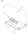
- Fig.3 and Fig. 4 are perspective views showing the method of transferring the FOUP by the vehicle according to the embodiment.
- a FOUP 400 is arranged on a port 510 just under the rail 100.
- the vehicle 200 first travels on the rail 100 and stops over the FOUP 400 arranged on the port 510.
- the hoisting unit 235 winds off the hoisting belts 240 and the gripping unit 250 descends to the position of the FOUP 400. Then, a fine adjustment of the positions of the gripping unit 250 and the FOUP 400 is performed and the FOUP 400 is gripped.
- the hoisting belts 240 are reeled and the FOUP 400 gripped by the gripping unit 250 and the gripping unit 250 ascends to the position of the main body member 220. Then, the vehicle 200 again travels on the rail 100 and conveys the FOUP 400.
- the FOUP 400 is arranged at a side buffer 520 at the side of the rail 100.
- the moving unit 230 first moves to the side of the rail 100.
- the hoisting belts 240 are wound off by the hoisting unit 235 and the gripping unit 250 descends to the position of the FOUP 400.
- a lateral transfer of the FOUP 400 from the rail unit 100 can be performed.
- Fig. 5 is a perspective view showing the structures of the falling prevention member and the swing inhibiting member.
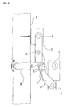
- Fig. 6 through Fig. 9 are bottom views showing the operations of the falling prevention member and the swing inhibiting member when they are projected.
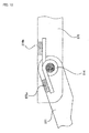
- Fig. 10 is a plan view showing the concrete structure of the biasing member.
- the falling prevention member 260 and the swing inhibiting member 270 are arranged at the lower end side of the conveying unit 220.
- the falling prevention member 260 is configured to project to the position where the carried FOUP 400 can be supported from the lower side of the FOUP 400 when the FOUP 400 is carried.
- the swing inhibiting member 270 is configured to project to the position where the side surface of the carried FOUP 400 can be pushed when the FOUP 400 is carried. It should be noted that the falling prevention member 260 and the swing inhibiting member 270 are rotated by driving force provided from motors, which are not shown in the figure, and etc.
- the falling prevention member 260 is attached to the conveying unit 220 so as to rotate horizontally about a rotation axis 610.
- the swing inhibiting member 270 is attached to the conveying unit 220 so as to rotate horizontally about a rotation axis 620.
- the swing inhibiting member 270 includes a first lever member 271. a second lever member 272, a pushing member 273, and a biasing member 274.
- a base end side of the first lever member 271 is pivotally supported by the conveying unit 220.
- a base end side of the second lever member 272 is pivotally supported by a tip of the first lever member 271.
- the pushing member 273 is pivotally supported by a tip of the second lever member 272.
- the biasing member 274 is attached to the part where the first lever member 272 and the second lever member 272 are connected, for example, a center of the axis that pivotally supports them.
- the biasing member 274 is, for example, a torsional spring, a plate spring, and etc. It should be noted that the biasing member 274 is configured to apply a biasing force to the first lever member 271 and the second lever member 272 so as to align the first lever member 271 and the second lever member 272 in line.
- a roller 265 as one example of "a projecting unit” of the present invention is attached to the falling prevention member 260.
- a roller guide 275 as one example of "a force receiving guide” of the present invention is attached to the first lever member 271 in the swing inhibiting member 270.
- the roller guide 275 is in a form of a metal plate.
- the roller guide 275 is arranged at the position where the roller 265 abuts the roller guide 275 when the falling prevention member 260 projects.
- the falling prevention member 260 rotates. As the falling prevention member 260 rotates toward the FOUP 400, the roller 265 abuts the roller guide 275. After the roller 265 abuts the roller guide 275, the roller 265 pushes the roller guide 275, and the first lever member 271 of the swing inhibiting member 270 rotates. Thus, the falling prevention member 260 and the swing inhibiting member 270 project together.
- the pushing surface of the pushing member 273 projects to the position where the pushing surface abuts the side surface of the FOUP 400 when the first lever member 271 rotates.
- the biasing force by the biasing member 274 is not generated because the positional relationship between the first lever member 271 and the second lever member 272 is the relationship where they are aligned in line.
- a force shown with an arrow P1 in the figure is applied to the pushing member 273 from the side surface of the FOUP 400.
- the falling prevention member 260 rotates in a direction shown with an arrow P2 in the figure, with the rotation axis 610 being the axis for this rotation.
- the rotating roller 265 abuts a stopper 275s of the roller guide 275, the falling prevention member 260 does not rotate in the direction shown with the arrow P2 in the figure.
- the above-described mechanism with which the pushing member 273 does not move even if pushed by the FOUP 400 can keep the falling prevention member 260 in an appropriate position.
- only a rotating force from a motor, not an external force can move the falling prevention member 260 and the falling prevention member 260 can stay in the appropriate position without a brake and etc.
- one end of the biasing member 274 which is a torsional spring, is attached to the first lever member 271 via a buffering material 276a.
- Another end of the biasing member 274 is attached to the second lever member 272 via a buffering material 276b.
- These buffering materials 276a and 276b can damp rapidly the swing transmitted from the FOUP 400. It should be noted that the same effect can be obtained even when an other member such as a plane spring is used as the biasing member 274. It is shown here that the buffering materials 276a and 276b are directly attached to the first lever member 271 and the second lever member 272, respectively. Instead, it is acceptable that receiving members, connection members, or etc. are arranged to the first lever member 271 and the second lever member 272 and the buffering members 276a and 276b are attached to the receiving members, the connection members, or etc.
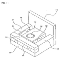
- Fig. 11 is a perspective view showing the structure of the pushing member of the swing inhibiting member.
- Fig. 12 is a plan view showing the structure of the pushing member of the swing inhibiting member.
- an elastic body (not shown in the figure) is attached to the pushing surface of a pushing surface member 710 of the pushing member 273 that abuts the FOUP.
- the pushing surface member 710 can push elastically the FOUP 400.
- a first longitudinal member 721 and a second longitudinal member 722 are attached to the side opposite to the pushing surface of the pushing surface member 710. If a part of the first longitudinal member or the second longitudinal member where the pushing surface member 710 is attached is called a base end part, the first longitudinal member 721 and the second longitudinal member 722 are attached to the pushing surface member 710 at their base end parts.
- a first lateral member 731 and a second lateral member 732 are attached to the tip side of the first longitudinal member 721 and the tip side of the second longitudinal member 722.
- the first lateral member 731 and the second lateral member 732 connects the tip part of the first longitudinal member 721 and the tip part of the second longitudinal member 722 with each other.
- a shaft 740 is arranged between the first longitudinal member 721 and the second longitudinal member 722. The shaft 740 is attached to the first lateral member 731 and the second lateral member 732.
- the shaft 740 inserts a block member 750 arranged in a gap between the first longitudinal member 721 and the second longitudinal member 722.
- a through hole (not shown in the figure) is formed in the block member 750 and the shaft 740 is inserted into this through hole.
- the block member 750 can slide in a longitudinal direction of the shaft.
- a projecting plate portion 751 that projects in a direction away from the pushing surface 710 is formed in the block member 750.
- the projecting plate portion 751 is arranged in a gap formed between the first lateral member 731 and the second lateral member 732 so as to slide along this gap.
- the shaft 740 and the slide mechanism that is formed by the first lateral member 731 and the second lateral member 732 can prevent the block member 750 from moving in a direction other than the direction in which the block member 750 should slide.
- the damage of the block member 750 can be avoided.
- the block member 750 is one example of "a main body member" of the present invention and is attached to the tip of the second lever member 272 via a connecting unit 752 (See Fig. 6 though Fig. 9 ).
- the block member 750 is typically made of a metal, etc.
- the block member 750 may be made of a resin with lower friction coefficient, etc. In this case, it is possible to omit a bush, etc.
- a first elastic body 761 is arranged in a gap between the block member 750 and the first longitudinal member 721.
- the first elastic body 761 is stuck to the first longitudinal member 721, and not to the block member 750.
- a second elastic body 762 is arranged in a gap between the block member 750 and the second longitudinal member 722.
- the second elastic body 762 is stuck to the second longitudinal member 722, and not to the block member 750.
- the first elastic body 761 and the second elastic body 762 is made of, for example, rubber, sponge, a gel material, or etc.
- the material for the first elastic body 761 and the second elastic body 762 is not limited to the above. It is acceptable they are, for example, metal elastic bodies such as coil springs, etc.
- a pair of these elastic bodies 761 and 762 can also slide elastically the block member 750.
- the above-described pushing member 273 can prevent the vibration transmitted from the second lever member 272 from transmitting to the pushing surface member 710. More specifically, the pushing member 273 can prevent the vibration generated in the travelling unit 210 and transmitted from the conveying unit 220 from transmitting to the pushing surface member 710.
- the overhead transport vehicle since the overhead transport vehicle according to this embodiment comprises the swing inhibiting member 270, it is possible to inhibit effectively the transmission of the vibration and the swing of the FOUP 400.
- the present invention is broadly applied to an overhead transport vehicle.
Landscapes
- Engineering & Computer Science (AREA)
- Mechanical Engineering (AREA)
- Transportation (AREA)
- Warehouses Or Storage Devices (AREA)
- Container, Conveyance, Adherence, Positioning, Of Wafer (AREA)
- Carriers, Traveling Bodies, And Overhead Traveling Cranes (AREA)
- Load-Engaging Elements For Cranes (AREA)
- Machines For Laying And Maintaining Railways (AREA)
- Chain Conveyers (AREA)
Abstract
Description
- This invention relates to an overhead transport vehicle, particularly to an overhead transport vehicle that conveys an article such as a container, etc. that contains various kinds of substrates and etc. for manufacturing a semiconductor equipment on a rail.
- An overhead hoist vehicle (so-called OHT: Overhead Hoist Transport) is known as a conventional conveying vehicle. The overhead hoist vehicle conveys an article such as a FOUP (Front Opening Unified Pod) and etc. by travelling on a rail arranged on a ceiling. Such conveying vehicle may comprise a falling prevention member and a swing inhibiting member. The falling prevention member is configured to prevent the article from falling, by projecting under the transferred article. The swing inhibiting member is configured to rotate in conjunction with a movement of the falling prevention member and is configured to inhibit swing by pushing the article. For example, patent citation 1 discloses a mechanism that pushes an elastic body such as a gel and etc. with a linear movement mechanism, the linear movement mechanism working with the falling prevention member. On the other hand, patent citation 2 discloses a mechanism in which a pushing member is directly attached to the falling prevention member.
- Patent Citation 1: Japanese Laid Open Patent Application No.
2009-040563 - Patent Citation 2: Japanese Laid Open Patent Application No.
2003-165687 - However, the technique according to the above-mentioned patent citation 1 requires a larger space to arrange the linear movement mechanism, which may result in both making equipment larger and reducing space for arranging other members. In addition, since there is a gap between a pushing part of a roller and a part sliding linearly, the swing inhibiting member may be damaged.
- Moreover, in the techniques according to patent citation 1 and patent citation 2, the article is restricted by an elastic force of the pushing member. In this case, since an amount of expansion and contraction of the pushing member is small, an acceptable amount of swing, of the article in a travelling direction and a direction crossing the travelling direction, becomes small. The vibrations generated in the conveying vehicles are easily transmitted to the article, thus, it is a technical problem in the techniques according to patent citation 1 and patent citation 2.
- This invention is carried out in light of the above-described problem, and the problem to be solved is to provide a conveying vehicle and a conveying system that can effectively reduce the transmission of the swing and vibrations to the article.
- A conveying vehicle according to the present invention comprises a travelling unit, a conveying unit, and a swing inhibiting member. The travelling unit is configured to travel on a rail arranged on or near a ceiling. The conveying unit is attached to the travelling unit, and configured to both move an article into a containing space and convey the article. The swing inhibiting member is pivotally supported by the conveying unit. The swing inhibiting member is configured to move between a pushing position, and a retracting position. The pushing position is a position from which a side surface of the article is pushed. The retracting position is a position away from the pushing position enabling the swing inhibiting member to move the article into the containing space.
The swing inhibiting member includes a pushing member, a lever member, and a biasing member. The pushing member is configured to push the side surface of the article. A first end side of the lever member is configured to support the pushing member. A second end side of the lever member is pivotally supported by the conveying unit. The biasing member is arranged in the lever member, and is configured to bias the pushing member to the article.
The pushing member includes a main body member, a slide member, and elastic bodies. The main body member is pivotally supported by the lever member. The slide member includes a pushing surface to be abutted the article. The slide member is supported by the main body member so as to slide in a direction crossing a travelling direction of the conveying vehicle (a slide direction). The elastic bodies are configured to elastically slide the slide member. The elastic bodies are arranged between the main body member and the slide member. - The conveying vehicle according to the present invention comprises the travelling unit, configured to travel on the rail arranged on or near the ceiling, and the conveying unit, which is attached to the travelling unit. In this conveying vehicle, the conveying unit is configured to move the article into a containing space, and the travelling unit is configured to travel on the rail, thus the article is conveyed. The conveying unit is typically attached to the travelling unit, and suspended from the travelling unit. The conveying unit includes a gripping member configured to grip the article, for example. When the conveying unit carries the article, the article gripped by the gripping member is moved into the containing space. The containing space is defined as an U-shaped inner space that is opened downwardly, for example.
- The conveying vehicle according to the present invention comprises the swing inhibiting member. The swing inhibiting member is supported by the conveying unit. Specifically, the swing inhibiting member is supported by a lower end side of the conveying unit so as to rotate in a horizontal direction. It should be noted that "the lower end side" described here means a position low enough to push the article carried in the containing space from the side. It should also be noted that "the horizontal direction" means not only the direction completely horizontal but also covers a broader meaning such as a direction obliquely crossing the horizontal direction.
- The swing inhibiting member is configured to move between the pushing position and the retracting position. Specifically, this swing inhibiting member is configured to move from the pushing position to the retracting position, and vice versa, by rotating in the horizontal direction. More specifically, when the article is about to be carried, the swing inhibiting member is in a state where at least part of the swing inhibiting member is retracted so as to make enough space for the article to pass the space in the vicinity of an entrance of the containing space. On the other hand, after carrying the article, the swing inhibiting member is configured to push the side surface of the article by projecting to the side of the containing space (namely, the side of the article contained), thus preventing the article from swinging. It should be noted that "swing" described here means a larger swing that is generated by a centrifugal force generated when the article, that is transported on the conveying vehicle, travels on a curve.
- Specifically, the swing inhibiting member, according to the present invention, includes a pushing member, a lever member, and a biasing member. The pushing member is configured to push the side surface of the article. Specifically, the pushing member is configured to push, in a planar manner, the side surface of the article when the pushing member is at the pushing position. The lever member is configured to support the pushing member at the first end side. The second end side of the lever member is pivotally supported by the conveying unit. The biasing member is arranged in the lever member, and configured to bias the pushing member to the side of the article. The lever member is pivotally supported by the conveying unit. When the swing inhibiting member moves from the retracting position to the pushing position, the lever member rotates, and then the pushing member abuts the side surface of the article.
- As described above, in the swing inhibiting member, according to the present invention, the pushing member abuts the side surface of the article due to the rotation of the lever member pivotally supported by the conveying member. Here, it is assumed that the pushing member abuts the side surface of the article due to a linear movement of the swing inhibiting member. In such a case, a large space in a travelling direction is required to arrange a linear movement mechanism. Therefore, in such a structure, equipment may become larger, and the space for arranging other members may be reduced. On the other hand, the swing inhibiting member according to the present invention allows the pushing member to abut the side surface of the article by the rotation of the lever member. As a result, the swing inhibiting member can preferably be retracted within an extremely small space. Therefore, downsizing of an equipment can be realized.
- In addition, since the pushing member according to the present invention pushes the side surface of the article, the swing can reliably be inhibited even if the article swings in the direction crossing the pushing direction. For example, when the pushing member is configured to push the side surface of the article in a planar manner, and when the article swings in the direction crossing the pushing direction, the swing can reliably be inhibited. Moreover, the pushing member is configured to push the article, not only with the rotating force to the lever member, but also with the biasing force by the biasing member. With such a structure, since the pushing member can push the article while following the swing of the article, the swing of the article can be inhibited very effectively.
- Moreover, according to the present invention, the above-described pushing member includes the above-described main body member, the above-described slide member, and the above-described elastic bodies. The slide member is supported by the main body member in a manner such that it can slide in the slide direction.
- The main body member, pivotally supported by the lever member, enables an angle of a pushing surface to change, in accordance with an angle of the article, in the containing space. Therefore, the side surface of the article can be reliably pushed by the pushing surface. In addition, the slide member, slidably supported by the main body member, is able to absorb vibrations transmitted from the conveying vehicle, and to prevent transmission of the vibrations to the article. It should be noted that "vibration" described here means smaller swing generated in a travelling system of the conveying vehicle. The slide member is further configured to slide elastically by the elastic bodies. Therefore, the transmission of the vibrations to the article can reliably be inhibited.
- As explained above, according to the overhead transport vehicle of the present invention, it is possible to effectively inhibit the transmission of vibrations, and swing of the article.
- According to one aspect of the conveying vehicle of the present invention, in the pushing member, the main body member is formed in a block shape. The main body member includes a planar projecting plate portion projecting away from the pushing surface. The slide member includes a first and second longitudinal members, a lateral member, and a shaft member. The first and second longitudinal members are provided to the pushing surface and at both sides of the main body member with predetermined gaps from the main body member, respectively. The lateral member connects the first and second longitudinal members with each other, and is configured to support the projecting plate portion. The lateral member is configured to slide the projecting plate portion in the slide direction, and to avoid moving the projecting plate portion upward and downward. The shaft member is inserted into a through hole formed in the main body member. The shaft member is configured to slide relative to the main body member, and to connect the first and second longitudinal members with each other at a place between the pushing surface and the lateral member. The elastic bodies are arranged in the predetermined gap between the main body member and the first longitudinal member, and are disposed in the predetermined gap between the main body member and the second longitudinal member.
- According to this aspect of the invention, in the pushing member, the main body member is formed in a block shape, and configured to include the planar projecting plate portion. The projecting plate portion is supported by the lateral member of the slide member so as to slide in the slide direction, and so as to not move upward and downward. In the slide member, for example, the first and second longitudinal members are arranged at both sides of the main body member with the predetermined gaps from the main body member, respectively, as the first and second longitudinal members project, from both sides in a width direction of the pushing surface (namely, both ends of the side), to the main body member. In addition, the lateral member is arranged so as to connect the first and second longitudinal members with each other at the edge. With such a structure, the pushing member can be downsized easily, and upward and downward (namely, the directions different from the slide direction) movements of the main body member can be avoided. Therefore, the conveying vehicle can be damage-resistant.
- In addition, a pair of elastic bodies are arranged in the predetermined gap between the main body member and the first longitudinal member, and in the predetermined gap between the main body member and the second longitudinal member. In other words, the predetermined gap according to this aspect is arranged so that the gap is large enough to arrange a pair of the elastic bodies. A pair of the elastic bodies enables both the sliding to the first longitudinal member of the main body member, and the sliding to the second longitudinal member, to be preferably elastic sliding movements. Therefore, the transmission of vibrations to the article can effectively be inhibited.
- According to another aspect of the conveying vehicle of the present invention, the lever member has a first lever member and a second lever member. A first end side of the first lever member is pivotally supported by the transport vehicle. A first end side of the second lever member is pivotally supported by a second end side of the first lever member. A second end side of the second lever member is configured to pivotally support the pushing member. The biasing member is arranged at a place where the first lever member and the second lever member are connected with each other. The biasing member is configured to bias the second lever member so as to align the first lever member and the second lever member in line. In addition, the lever member further includes a driving force transmitting means configured to transmit a rotating force that rotates the first lever member to the article.
- According to this aspect, a base end side (the first end side) of the first lever member is pivotally supported by the conveying unit. In addition, a base end side (the first end side) of the second lever member is pivotally supported by a tip side (the second end side) of the first lever member. Moreover, the pushing member is attached to a tip side (the second end side) of the second lever member. The biasing member is arranged at the place where the first lever member and the second lever member are connected with each other. The biasing member is formed, for example, as a torsional spring. This biasing member is configured to bias the second lever member so as to align the first lever member and the second lever member in line.
- When the swing inhibiting member is in the retracting position, the first lever member and the second lever member are in a position where they are aligned in line. Therefore, the swing inhibiting member can be retracted in a compact size, and the downsizing of the swing inhibiting member can preferably be realized. On the other hand. when projecting the swing inhibiting member to the pushing position, the driving force transmitting means first transmits the rotating force to the first lever member, and then the first lever member and the second lever member rotate relative to the conveying unit. This allows the pushing member to abut the article. After the pushing member abuts the article, the first lever member continues rotating in the same manner. In such a state, the second lever member is dogleg, relative to the first lever member, and the biasing force from the biasing member is applied to the first lever member and the second lever member. With such a structure, even if the article swings largely in the pushing direction of the pushing member, the pushing member can follow the movement of the article and keep pushing the side surface of the article. Therefore, the swing of the article can extremely effectively be stopped.
- In the above-described structure comprising the driving force transmitting means, it is acceptable to configure the conveying vehicle as follows. The conveying vehicle further comprises a falling prevention member. The falling prevention member is pivotally supported by the conveying unit under the swing inhibiting member so as to rotate. The falling prevention member is configured to project under the article in conjunction with a movement of the swing inhibiting member, from the retraction position to the pushing position, and prevent the article from falling from the containing space. The driving force transmitting means includes a projecting unit and a force receiving guide. The projecting unit is arranged to the falling prevention member. The force receiving guide is arranged to the first lever member and configured to receive a force from the projecting unit.
- In this case, because the falling prevention member is arranged at the lower end side of the conveying unit than the swing inhibiting member, the falling prevention member can prevent the article contained in the containing space from falling. Specifically, the falling prevention member moves to project under the article and works in conjunction with the movement of the swing inhibiting member moving from the retracting position to the pushing position. Thus, for example, it is possible to receive an article that is about to fall from the containing space, due to the swing of the conveying vehicle from the lower side of the containing space.
The projecting unit as the driving force transmitting means is specially arranged to work with the above-described falling prevention member. On the other hand, the force receiving guide as the driving force transmitting means is arranged to work with the first lever member of the swing inhibiting member. The force receiving guide is configured to convert the force received from the projecting unit, to the rotating force of the first lever member. Therefore, it is possible to couple the falling prevention member to the swing inhibiting member, and move the falling prevention member and the swing inhibiting member with an extremely simple structure. - It is acceptable in the above-described structure, in which the lever member includes the first lever member and the second lever member, for the biasing member to be a torsional spring. The torsional spring is attached to the first lever member at the first end side and is attached to the second lever member at the second end side.
- In this case, since the first end side of the torsional spring is attached to the first lever member, and the second end side of the torsional spring is attached to the second lever member, it is possible to reliably generate the biasing force with which the first lever member and the second lever member utilize to align in line. In addition, since the torsional spring is low in cost and simple in structure, it is possible to avoid increasing the manufacturing cost and making the structure of the equipment complicated.
- It is acceptable, in the above-described structure in which the biasing member is a torsional spring, for the first end side of the torsional spring to abut the first lever member via a buffering member, and for the second end side of the torsional spring to abut the second lever member, via a buffering member.
- In this case, the buffering members are arranged between the torsional spring as the biasing member and the first lever member, and between the torsional spring and the second lever member. With such a buffering member, it is possible to extremely rapidly damp the swing, of the article pushed by the swing inhibiting member, in a biasing direction of the spring.
- It is acceptable, in the above-described structure in which the lever member includes the first lever member and the second lever member, for the biasing member to be a plate spring. The plate spring is configured to abut the first lever member at the first end side. and configured to abut the second lever member at the second end side.
- In this case, since the first end side of the plate spring abut the first lever member, and the second end side of the plate spring abuts the second lever member, it is possible to reliably generate the biasing force with which the first lever member and the second lever member utilize to align in line. In addition, since the plate spring is low in cost and simple in structure, it is possible to avoid increasing the manufacturing cost and complicatinging the structure of the equipment.
- It is acceptable in the above-described structure, in which the biasing member is a plate spring, for the first end side of the plate spring to abut the first lever member via a buffering member, and for the second end side of the plate spring to abut the second lever member, via a buffering member.
- In this case, the buffering members are arranged between the plate spring as the biasing member and the first lever member, and between the plate spring and the second lever member. With such a buffering member, it is possible to extremely rapidly damp the swing, of the article pushed by the swing inhibiting member, in a biasing direction of the spring.
- According to other aspect of the conveying vehicle of the present invention, the pushing member includes an elastic body arranged on at least one part of the pushing surface.
- In this structure, the elastic body is arranged on at least one part of the pushing surface abutting the article. This elastic body is different from the elastic body that enables the slide member to slide elastically. With this elastic body, since it is possible to push elastically the article, it is possible to avoid scratches on, and damage to, the article. In addition, it is possible to reliably damp the swing of the conveyed vehicle, and to inhibit the transmission of the vibration of the article.
- It should be noted that it is preferable that the other elastic body is arranged so as to cover the entire pushing surface. In addition, it is acceptable that other elastic body is arranged to the part other than the pushing surface.
Additional effects and merits of the invention will be clarified in the description of the embodiments that follow. - According to the present invention, it is possible to provide a conveying vehicle, and a conveying system, that effectively reduce the transmission of swings and vibrations to the article.
-
-
Fig. 1 is a top view showing an overall structure of a conveying system. -
Fig. 2 is a side view showing a structure of a vehicle. -
Fig. 3 is a perspective view showing a transferring operation of a vehicle. -
Fig. 4 is a perspective view showing a lateral transferring operation of a vehicle. -
Fig. 5 is a perspective view showing structures of a falling prevention member and a swing inhibiting member. -
Fig. 6 is a bottom view showing operations of a falling prevention member and a swing inhibiting member when they are projected (Part 1). -
Fig. 7 is a bottom view showing operations of a falling prevention member and a swing inhibiting member when they are projected (Part 2). -
Fig. 8 is a bottom view showing operations of a falling prevention member and a swing inhibiting member when they are projected (Part 3). -
Fig. 9 is a bottom view showing operations of a falling prevention member and a swing inhibiting member when they are projected (Part 4). -
Fig. 10 is a plan view showing a concrete structure of a biasing member. -
Fig. 11 is a perspective view showing a structure of a pushing member of a swing inhibiting member. -
Fig. 12 is a plan view showing a structure of a pushing member of a swing inhibiting member. -
- 100
- rail
- 200
- vehicle
- 210
- travelling unit
- 215
- travelling roller
- 220
- main body member
- 230
- moving unit
- 240
- hoisting belt
- 250
- gripping unit
- 260
- falling prevention member
- 265
- roller
- 270
- swing inhibiting member
- 271
- first lever member
- 272
- second lever member
- 273
- pushing member
- 274
- biasing member
- 275
- roller guide
- 300
- controller
- 400
- FOUP
- 510
- port
- 520
- side buffer
- 710
- pushing surface member
- 721
- first longitudinal member
- 722
- second longitudinal member
- 731
- first lateral member
- 732
- second lateral member
- 740
- shaft
- 750
- block member
- 751
- projecting plate portion
- 761, 762
- elastic body
- A preferred embodiment of the present invention will be explained below, referring to the figures.
- First, an overall structure of a conveying system according to the present invention will be explained, referring to
Fig. 1 . The conveying system according to the present invention comprises a vehicle as one example of "an overhead transport vehicle".Fig. 1 is a top view showing the overall structure of the conveying system. - In
Fig. 1 , the conveying system according to this embodiment comprises arail 100,vehicles 200, and acontroller 300. - The
rail 100 is arranged, for example, on a ceiling and made of metals such as aluminium, stainless steel, and etc. - A plurality of the
vehicles 200 are arranged on therail 100. Eachvehicle 200 can convey a FOUP as an article by travelling along therail 100. - In addition, each
vehicle 200 has anonboard controller 205. Theonboard controller 205 receives a conveying instruction from acontroller 300 and controls the travelling of thevehicle 200. It should be noted that theonboard controller 205 controls not only the travelling of thevehicle 200 but also overall equipments included in thevehicle 200. - The
controller 300 includes, for example, an arithmetic circuit, a memory, and etc. Thecontroller 300 is configured to provide the conveying instruction to thevehicle 200 via theonboard controller 205. - It should be noted that, although not shown in the figure, a shelf that stores temporarily a FOUP (for example, a buffer, a port, and etc.) and a semiconductor manufacturing equipment are arranged along the
rail 100. - Next, the concrete structure of the
vehicle 200 will be explained, referring toFig. 2. Fig. 2 is a side view showing the structure of the vehicle. - In
Fig. 2 , thevehicle 200 includes travellingunits 210, amain body member 220, a movingunit 230, ahoisting unit 235, agripping unit 250, a fallingprevention member 260, and aswing inhibiting member 270. - When a propulsion power is given to the travelling
units 210 by, for example, a linear motor and etc., travellingrollers 215 roll and thevehicle 200 travels along therail 100. On the lower surfaces of the travellingunits 210, themain body member 220 as one example of "a conveying unit" of the present invention is suspended. - The moving
unit 230 is attached to themain body member 220. The movingunit 230 can move to the sides of the rail 100 (namely, a vertical direction to the surface of paper inFig. 2 ). On the lower surface of the movingunit 230, thehoisting unit 235 is attached. - On the lower surface of the
hoisting unit 235, thegripping unit 250 configured to grip the FOUP is attached by a hoistingbelt 240. Thegripping unit 250 can descend or ascend by winding off the hoistingbelt 240 or reeling the hoistingbelt 240. - The falling
prevention members 260 are arranged in the vicinity of a lower end of themain body member 220. The fallingprevention members 260 are configured to prevent the FOUP from falling by projecting so as to support the carried FOUP at the lower side of the FOUP. - The
swing inhibiting members 270 are arranged at the position higher than the above-described fallingprevention members 260 in themain body member 220. Theswing inhibiting members 270 are configured to inhibit the swing by pushing the side surface of the carried FOUP. - The concrete structures and operations of the falling
prevention members 260 and theswing inhibiting members 270 will be described in detail later. - Next, a method of transferring the FOUP by the vehicle will be explained, referring to
Fig. 3 andFig. 4 .Fig.3 andFig. 4 are perspective views showing the method of transferring the FOUP by the vehicle according to the embodiment. - In
Fig. 3 , aFOUP 400 is arranged on aport 510 just under therail 100. In this case, thevehicle 200 first travels on therail 100 and stops over theFOUP 400 arranged on theport 510. - Next, as shown in
Fig. 3 , thehoisting unit 235 winds off the hoistingbelts 240 and thegripping unit 250 descends to the position of theFOUP 400. Then, a fine adjustment of the positions of thegripping unit 250 and theFOUP 400 is performed and theFOUP 400 is gripped. - When the
FOUP 400 is gripped, the hoistingbelts 240 are reeled and theFOUP 400 gripped by thegripping unit 250 and thegripping unit 250 ascends to the position of themain body member 220. Then, thevehicle 200 again travels on therail 100 and conveys theFOUP 400. - In
Fig. 4 , theFOUP 400 is arranged at aside buffer 520 at the side of therail 100. In this case, the movingunit 230 first moves to the side of therail 100. Then, the hoistingbelts 240 are wound off by thehoisting unit 235 and thegripping unit 250 descends to the position of theFOUP 400. By operating this way, a lateral transfer of theFOUP 400 from therail unit 100 can be performed. - Next, the concrete structures and operations of the falling
prevention member 260 and theswing inhibiting member 270 will be explained in detail, referring toFig. 5 through Fig. 10 .Fig. 5 is a perspective view showing the structures of the falling prevention member and the swing inhibiting member. In addition,Fig. 6 through Fig. 9 are bottom views showing the operations of the falling prevention member and the swing inhibiting member when they are projected.Fig. 10 is a plan view showing the concrete structure of the biasing member. - In
Fig. 5 , the fallingprevention member 260 and theswing inhibiting member 270 are arranged at the lower end side of the conveyingunit 220. The fallingprevention member 260 is configured to project to the position where the carriedFOUP 400 can be supported from the lower side of theFOUP 400 when theFOUP 400 is carried. Theswing inhibiting member 270 is configured to project to the position where the side surface of the carriedFOUP 400 can be pushed when theFOUP 400 is carried. It should be noted that the fallingprevention member 260 and theswing inhibiting member 270 are rotated by driving force provided from motors, which are not shown in the figure, and etc. - In
Fig. 6 . the fallingprevention member 260 is attached to the conveyingunit 220 so as to rotate horizontally about arotation axis 610. On the other hand, theswing inhibiting member 270 is attached to the conveyingunit 220 so as to rotate horizontally about arotation axis 620. Theswing inhibiting member 270 includes afirst lever member 271. asecond lever member 272, a pushingmember 273, and a biasingmember 274. - More specifically, a base end side of the
first lever member 271 is pivotally supported by the conveyingunit 220. A base end side of thesecond lever member 272 is pivotally supported by a tip of thefirst lever member 271. The pushingmember 273 is pivotally supported by a tip of thesecond lever member 272. The biasingmember 274 is attached to the part where thefirst lever member 272 and thesecond lever member 272 are connected, for example, a center of the axis that pivotally supports them. The biasingmember 274 is, for example, a torsional spring, a plate spring, and etc. It should be noted that the biasingmember 274 is configured to apply a biasing force to thefirst lever member 271 and thesecond lever member 272 so as to align thefirst lever member 271 and thesecond lever member 272 in line. - A
roller 265 as one example of "a projecting unit" of the present invention is attached to the fallingprevention member 260. Aroller guide 275 as one example of "a force receiving guide" of the present invention is attached to thefirst lever member 271 in theswing inhibiting member 270. Theroller guide 275 is in a form of a metal plate. Theroller guide 275 is arranged at the position where theroller 265 abuts theroller guide 275 when the fallingprevention member 260 projects. When theFOUP 400 is transferred to thevehicle 200, the fallingprevention member 260 and theswing inhibiting member 270 are retracted so as not to project to theFOUP 400 in order not to interfere with the transfer of theFOUP 400 to the vehicle 200 (SeeFig. 6 ). - As shown in
Fig. 7 , when theFOUP 400 is transferred, the fallingprevention member 260 rotates. As the fallingprevention member 260 rotates toward theFOUP 400, theroller 265 abuts theroller guide 275. After theroller 265 abuts theroller guide 275, theroller 265 pushes theroller guide 275, and thefirst lever member 271 of theswing inhibiting member 270 rotates. Thus, the fallingprevention member 260 and theswing inhibiting member 270 project together. - As shown in
Fig. 8 , in theswing inhibiting member 270, the pushing surface of the pushingmember 273 projects to the position where the pushing surface abuts the side surface of theFOUP 400 when thefirst lever member 271 rotates. At the stage ofFig. 8 , the biasing force by the biasingmember 274 is not generated because the positional relationship between thefirst lever member 271 and thesecond lever member 272 is the relationship where they are aligned in line. - As shown in
Fig. 9 , when thefirst lever member 271 further rotates even after the pushing surface of the pushingmember 273 abuts the side surface of theFOUP 400, thesecond lever member 272 bends relative to thefirst lever member 271. In this state, the biasingmember 274 generates the biasing force that aligns thefirst lever member 271 and thesecond lever member 272 in line. In other words, the force to bias thesecond lever member 272 toward the FOUP is applied to thesecond lever member 272. Thus, the pushingmember 273 pushes theFOUP 400 while the pushingmember 273 follows theFOUP 400. Therefore, thisswing inhibiting member 270 can inhibit the swing of theFOUP 400 more effectively than the case where only a rotating force of thefirst lever member 271 pushes theFOUP 400. - It should be noted that a force shown with an arrow P1 in the figure is applied to the pushing
member 273 from the side surface of theFOUP 400. In this case, it may happen that the fallingprevention member 260 rotates in a direction shown with an arrow P2 in the figure, with therotation axis 610 being the axis for this rotation. However, since therotating roller 265 abuts astopper 275s of theroller guide 275, the fallingprevention member 260 does not rotate in the direction shown with the arrow P2 in the figure. In other words, the above-described mechanism with which the pushingmember 273 does not move even if pushed by theFOUP 400 can keep the fallingprevention member 260 in an appropriate position. Specifically, only a rotating force from a motor, not an external force, can move the fallingprevention member 260 and the fallingprevention member 260 can stay in the appropriate position without a brake and etc. - In
Fig. 10 , one end of the biasingmember 274, which is a torsional spring, is attached to thefirst lever member 271 via abuffering material 276a. Another end of the biasingmember 274 is attached to thesecond lever member 272 via abuffering material 276b. Thesebuffering materials FOUP 400. It should be noted that the same effect can be obtained even when an other member such as a plane spring is used as the biasingmember 274. It is shown here that thebuffering materials first lever member 271 and thesecond lever member 272, respectively. Instead, it is acceptable that receiving members, connection members, or etc. are arranged to thefirst lever member 271 and thesecond lever member 272 and thebuffering members - Next, the concrete structure of the pushing
member 273 of the above-describedswing inhibiting member 270 will be explained, referring toFig. 11 andFig. 12 .Fig. 11 is a perspective view showing the structure of the pushing member of the swing inhibiting member.Fig. 12 is a plan view showing the structure of the pushing member of the swing inhibiting member. - In
Fig. 11 , an elastic body (not shown in the figure) is attached to the pushing surface of a pushingsurface member 710 of the pushingmember 273 that abuts the FOUP. Thus, the pushingsurface member 710 can push elastically theFOUP 400. A firstlongitudinal member 721 and a secondlongitudinal member 722 are attached to the side opposite to the pushing surface of the pushingsurface member 710. If a part of the first longitudinal member or the second longitudinal member where the pushingsurface member 710 is attached is called a base end part, the firstlongitudinal member 721 and the secondlongitudinal member 722 are attached to the pushingsurface member 710 at their base end parts. On the other hand, if the side opposite to the base end part of the firstlongitudinal member 721 or the secondlongitudinal member 722 is called a tip part, A firstlateral member 731 and a secondlateral member 732 are attached to the tip side of the firstlongitudinal member 721 and the tip side of the secondlongitudinal member 722. In other words, the firstlateral member 731 and the secondlateral member 732 connects the tip part of the firstlongitudinal member 721 and the tip part of the secondlongitudinal member 722 with each other. In addition, ashaft 740 is arranged between the firstlongitudinal member 721 and the secondlongitudinal member 722. Theshaft 740 is attached to the firstlateral member 731 and the secondlateral member 732. - The
shaft 740 inserts ablock member 750 arranged in a gap between the firstlongitudinal member 721 and the secondlongitudinal member 722. In more detail, a through hole (not shown in the figure) is formed in theblock member 750 and theshaft 740 is inserted into this through hole. Thus, theblock member 750 can slide in a longitudinal direction of the shaft. In addition, a projectingplate portion 751 that projects in a direction away from the pushingsurface 710 is formed in theblock member 750. The projectingplate portion 751 is arranged in a gap formed between the firstlateral member 731 and the secondlateral member 732 so as to slide along this gap. Thus, theshaft 740 and the slide mechanism that is formed by the firstlateral member 731 and the secondlateral member 732 can prevent theblock member 750 from moving in a direction other than the direction in which theblock member 750 should slide. Thus, the damage of theblock member 750 can be avoided. It should be noted that theblock member 750 is one example of "a main body member" of the present invention and is attached to the tip of thesecond lever member 272 via a connecting unit 752 (SeeFig. 6 thoughFig. 9 ). Theblock member 750 is typically made of a metal, etc. It should be noted that theblock member 750 may be made of a resin with lower friction coefficient, etc. In this case, it is possible to omit a bush, etc. - As shown in
Fig. 11 andFig. 12 , a firstelastic body 761 is arranged in a gap between theblock member 750 and the firstlongitudinal member 721. The firstelastic body 761 is stuck to the firstlongitudinal member 721, and not to theblock member 750. On the other hand, a secondelastic body 762 is arranged in a gap between theblock member 750 and the secondlongitudinal member 722. The secondelastic body 762 is stuck to the secondlongitudinal member 722, and not to theblock member 750. The firstelastic body 761 and the secondelastic body 762 is made of, for example, rubber, sponge, a gel material, or etc. However, the material for the firstelastic body 761 and the secondelastic body 762 is not limited to the above. It is acceptable they are, for example, metal elastic bodies such as coil springs, etc. A pair of theseelastic bodies block member 750. - The above-described pushing
member 273 can prevent the vibration transmitted from thesecond lever member 272 from transmitting to the pushingsurface member 710. More specifically, the pushingmember 273 can prevent the vibration generated in the travellingunit 210 and transmitted from the conveyingunit 220 from transmitting to the pushingsurface member 710. - As described above, since the overhead transport vehicle according to this embodiment comprises the
swing inhibiting member 270, it is possible to inhibit effectively the transmission of the vibration and the swing of theFOUP 400. - The present invention is not limited to the above-described embodiment and can be arbitrarily changed without departing from the scope or concept of the invention that can be read from the claims and the entire specification. The conveying system including such change is also within the scope of the invention.
- The present invention is broadly applied to an overhead transport vehicle.
Claims (9)
- A overhead transport vehicle comprising:a travelling unit configured to travel on a rail arranged on or near a ceiling:a conveying unit attached to the travelling unit, the conveying unit configured to move an article into a containing space and convey the article;a swing inhibiting member pivotally supported by the conveying unit, the swing inhibiting member configured to move between a pushing position and a retracting position, the pushing position being where a side surface of the article is pushed, and the retracting position being away from the pushing position so as to move the article into the containing space;the swing inhibiting member including:a pushing member configured to push the side surface of the article;a lever member having a first end side and a second end side, the first end side configured to support the pushing member, and the second end side pivotally supported by the conveying unit; anda biasing member arranged in the lever member, the biasing member configured to bias the pushing member toward the article;the pushing member including:a main body member pivotally supported by the lever member;a slide member including a pushing surface to abut the article, the slide member supported by the main body member and configured to slide in a slide direction crossing a travelling direction of the transport vehicle; andelastic bodies arranged between the main body member and the slide member, the elastic bodies configured to elastically slide the slide member.
- The overhead transport vehicle according to claim 1, wherein
the main body member is formed in a block shape, the main body member including a planar projecting plate portion, the planar projecting plate portion projecting away from the pushing surface;
the slide member further includes:first and second longitudinal members abutting the pushing surface and disposed at both sides of the main body member with predetermined gaps from the main body member, respectively;a lateral member connecting the first and second longitudinal members, and the lateral member configured to:support the projecting plate portion,slide the projecting plate portion in the slide direction, andprevent movement of the projecting plate portion in the upward and downward directions; anda shaft member inserted into a through hole formed in the main body member, the shaft member configured to:slide relative to the main body member, andconnect the first and second longitudinal members with each other ata place between the pushing surface and the lateral member; andwherein the elastic bodies are arranged in the predetermined gap between the main body member and the first longitudinal member and in the predetermined gap between the main body member and the second longitudinal member. - The overhead transport vehicle according to claim 1, wherein
the lever member includes a first lever member and a second lever member;
wherein a first end side of the first lever member is pivotally supported by the conveying vehicle, a first end side of the second lever member is pivotally supported by a second end side of the first lever member, and a second end side of the second lever member pivotally supports the pushing member;
the biasing member is arranged at a place where the first lever member and the second lever member are connected with each other, and
the biasing member is further configured to bias the second lever member, and align the first lever member and the second lever member in line; and
the lever member further includes a driving force transmitting means, the driving force transmitting means configured to transmit a rotating force that rotates the first lever member towards the article. - The overhead transport vehicle according to claim 3 further comprising:a falling prevention member pivotally supported by the conveying unit under the swing inhibiting member to rotate, the falling prevention member configured to prevent the article from falling from the containing space by projecting under the article in conjunction with a movement of the swing inhibiting member, the movement of the swing inhibiting member when it moves from the retracting position to the pushing position;the driving force transmitting means including a projecting member and a force receiving guide, the projecting member provided on the falling prevention member, the force receiving guide provided on the first lever member, and the force receiving guide configured to receive a force from the projecting member.
- The overhead transport vehicle according to 3, wherein
the biasing member is a torsional spring;
a first end side of the torsional spring is attached to the first lever member; and
a second end side of the torsional spring is attached to the second lever member. - The overhead transport vehicle according to claim 5, wherein
the first end side of the torsional spring abuts the first lever member via a first buffering member; and
the second end side of the torsional spring abuts the second lever member via a second buffering member. - The overhead transport vehicle according to claim 3, wherein
the biasing member is a plate spring;
a first end side of the plate spring is configured to abut the first lever member; and a second end side of the plate spring is configured to abut the second lever member. - The overhead transport vehicle according to claim 7, wherein
the first end side of the plate spring abuts the first lever member via a buffering member; and
the second end side of the plate spring abuts the second lever member via a buffering member. - The overhead transport vehicle according to claim 1, wherein
the pushing member includes an elastic body attached on at least one part of the pushing surface.
Applications Claiming Priority (2)
| Application Number | Priority Date | Filing Date | Title |
|---|---|---|---|
| JP2011029674A JP5750926B2 (en) | 2011-02-15 | 2011-02-15 | Ceiling transport vehicle |
| PCT/JP2011/078410 WO2012111221A1 (en) | 2011-02-15 | 2011-12-08 | Overhead transport vehicle |
Publications (3)
| Publication Number | Publication Date |
|---|---|
| EP2676916A1 true EP2676916A1 (en) | 2013-12-25 |
| EP2676916A4 EP2676916A4 (en) | 2014-09-17 |
| EP2676916B1 EP2676916B1 (en) | 2017-03-01 |
Family
ID=46672171
Family Applications (1)
| Application Number | Title | Priority Date | Filing Date |
|---|---|---|---|
| EP11858523.1A Not-in-force EP2676916B1 (en) | 2011-02-15 | 2011-12-08 | Overhead transport vehicle |
Country Status (8)
| Country | Link |
|---|---|
| US (1) | US8726811B2 (en) |
| EP (1) | EP2676916B1 (en) |
| JP (1) | JP5750926B2 (en) |
| KR (1) | KR101532993B1 (en) |
| CN (1) | CN103370272B (en) |
| SG (1) | SG192035A1 (en) |
| TW (1) | TWI543924B (en) |
| WO (1) | WO2012111221A1 (en) |
Families Citing this family (26)
| Publication number | Priority date | Publication date | Assignee | Title |
|---|---|---|---|---|
| JP5273118B2 (en) * | 2010-10-04 | 2013-08-28 | 村田機械株式会社 | Transport vehicle and transport system |
| JP5750926B2 (en) * | 2011-02-15 | 2015-07-22 | 村田機械株式会社 | Ceiling transport vehicle |
| SG11201605180TA (en) * | 2014-01-07 | 2016-08-30 | Murata Machinery Ltd | Transfer device and control method of transfer device |
| JP6477439B2 (en) * | 2015-11-17 | 2019-03-06 | 株式会社ダイフク | Goods transport equipment |
| JP6471702B2 (en) * | 2016-01-12 | 2019-02-20 | 株式会社ダイフク | Article conveying device |
| CN105668171B (en) * | 2016-03-31 | 2018-02-16 | 广东科技学院 | Dish delivery system |
| JP6801476B2 (en) * | 2017-02-01 | 2020-12-16 | 村田機械株式会社 | Ceiling carrier |
| WO2018142811A1 (en) * | 2017-02-06 | 2018-08-09 | 村田機械株式会社 | Overhead conveyance vehicle |
| US10557262B2 (en) | 2017-06-16 | 2020-02-11 | Mccain Manufacturing, Inc. | Modular panels and related elements to form a variety of wall segments and enclosures |
| JP6717275B2 (en) * | 2017-09-19 | 2020-07-01 | 井関農機株式会社 | Work vehicle |
| WO2019146276A1 (en) * | 2018-01-24 | 2019-08-01 | 村田機械株式会社 | Transport vehicle |
| US12145633B2 (en) * | 2018-02-01 | 2024-11-19 | Carl Anthony Salmon | Multifunctional track system with independently movable vehicles |
| KR102615063B1 (en) | 2018-03-08 | 2023-12-19 | 엘지전자 주식회사 | water dispensing apparatus |
| JP6881486B2 (en) * | 2019-02-27 | 2021-06-02 | 村田機械株式会社 | Transport vehicle |
| JP7224728B2 (en) * | 2019-04-23 | 2023-02-20 | 株式会社ディスコ | Conveyor system |
| US11570958B2 (en) * | 2019-09-20 | 2023-02-07 | Mjnn Llc | Catch mechanism facilitating loading of vertical grow towers onto grow lines in a vertical farm system |
| WO2021181923A1 (en) * | 2020-03-13 | 2021-09-16 | 村田機械株式会社 | Gripper device, conveyance vehicle, and conveyance method |
| JP7318596B2 (en) * | 2020-06-29 | 2023-08-01 | 株式会社ダイフク | Goods carrier |
| KR102789354B1 (en) * | 2020-08-26 | 2025-03-31 | 세메스 주식회사 | Unit for supporting object and vehicle having the same |
| KR102412362B1 (en) * | 2020-09-08 | 2022-06-23 | 주식회사 에스에프에이 | Transfer vehicle and transfer vehicle system having the same |
| KR102534256B1 (en) * | 2020-12-18 | 2023-05-17 | 세메스 주식회사 | Transport vehicle for supressing vibration of article and article transport system of manufacturing factory including the same |
| JP7359171B2 (en) * | 2021-02-17 | 2023-10-11 | 株式会社ダイフク | Goods transport vehicle |
| JP7729276B2 (en) * | 2022-07-08 | 2025-08-26 | 株式会社ダイフク | Goods transport vehicle |
| JP2025009152A (en) * | 2023-07-07 | 2025-01-20 | 株式会社ディスコ | Transport vehicle |
| TWI871123B (en) * | 2023-12-05 | 2025-01-21 | 旭東機械工業股份有限公司 | Device for transferring wafer box |
| CN120383259B (en) * | 2025-06-27 | 2025-09-23 | 上海果纳半导体技术有限公司 | Stop device and elevator having the same |
Family Cites Families (20)
| Publication number | Priority date | Publication date | Assignee | Title |
|---|---|---|---|---|
| DE2402258C3 (en) | 1973-04-14 | 1980-01-03 | Chemische Fabrik Pfersee Gmbh, 8900 Augsburg | Use of condensation products to handle textile materials |
| JPS503199U (en) * | 1973-05-07 | 1975-01-14 | ||
| JPS6111626U (en) * | 1984-06-27 | 1986-01-23 | 株式会社東芝 | Delivery device |
| JP2003165687A (en) | 2001-11-30 | 2003-06-10 | Murata Mach Ltd | Ceiling conveying vehicle |
| US10957569B2 (en) * | 2002-10-11 | 2021-03-23 | Murata Machinery Ltd. | Access to one or more levels of material storage shelves by an overhead hoist transport vehicle from a single track position |
| JP3981885B2 (en) * | 2003-05-20 | 2007-09-26 | 株式会社ダイフク | Transport device |
| JP4123383B2 (en) * | 2004-08-12 | 2008-07-23 | 村田機械株式会社 | Overhead traveling vehicle system |
| JP4794854B2 (en) * | 2004-12-14 | 2011-10-19 | 古河機械金属株式会社 | Drum wire rope random winding prevention device |
| JP4221603B2 (en) * | 2005-03-31 | 2009-02-12 | 村田機械株式会社 | Overhead traveling vehicle system |
| JP4394027B2 (en) * | 2005-04-05 | 2010-01-06 | 村田機械株式会社 | Overhead traveling vehicle system |
| JP4720267B2 (en) * | 2005-04-14 | 2011-07-13 | 村田機械株式会社 | Overhead traveling vehicle system |
| JP2007191235A (en) * | 2006-01-17 | 2007-08-02 | Murata Mach Ltd | Overhead traveling vehicle system |
| JP4688824B2 (en) * | 2007-01-12 | 2011-05-25 | 村田機械株式会社 | Overhead traveling vehicle system and method for carrying in / out of processing device around overhead traveling vehicle system |
| JP5169065B2 (en) * | 2007-08-09 | 2013-03-27 | 村田機械株式会社 | Holding mechanism and transport device |
| JP4807424B2 (en) * | 2009-03-17 | 2011-11-02 | 村田機械株式会社 | Ceiling transfer system and article transfer method |
| JP5518513B2 (en) * | 2010-02-04 | 2014-06-11 | 平田機工株式会社 | Hoop opener and operation method thereof |
| WO2011125097A1 (en) * | 2010-04-02 | 2011-10-13 | ムラテックオートメーション株式会社 | Side buffer for a transport vehicle that travels along the ceiling, and transport vehicle system |
| JP5273118B2 (en) * | 2010-10-04 | 2013-08-28 | 村田機械株式会社 | Transport vehicle and transport system |
| JP5750926B2 (en) * | 2011-02-15 | 2015-07-22 | 村田機械株式会社 | Ceiling transport vehicle |
| US9360772B2 (en) * | 2011-12-29 | 2016-06-07 | Nikon Corporation | Carrier method, exposure method, carrier system and exposure apparatus, and device manufacturing method |
-
2011
- 2011-02-15 JP JP2011029674A patent/JP5750926B2/en not_active Expired - Fee Related
- 2011-12-08 CN CN201180067563.7A patent/CN103370272B/en not_active Expired - Fee Related
- 2011-12-08 KR KR1020137022677A patent/KR101532993B1/en not_active Expired - Fee Related
- 2011-12-08 US US13/985,542 patent/US8726811B2/en not_active Expired - Fee Related
- 2011-12-08 WO PCT/JP2011/078410 patent/WO2012111221A1/en not_active Ceased
- 2011-12-08 SG SG2013055058A patent/SG192035A1/en unknown
- 2011-12-08 EP EP11858523.1A patent/EP2676916B1/en not_active Not-in-force
-
2012
- 2012-02-14 TW TW101104732A patent/TWI543924B/en not_active IP Right Cessation
Also Published As
| Publication number | Publication date |
|---|---|
| WO2012111221A1 (en) | 2012-08-23 |
| CN103370272A (en) | 2013-10-23 |
| JP5750926B2 (en) | 2015-07-22 |
| US20140047995A1 (en) | 2014-02-20 |
| EP2676916B1 (en) | 2017-03-01 |
| TW201236961A (en) | 2012-09-16 |
| TWI543924B (en) | 2016-08-01 |
| CN103370272B (en) | 2015-04-15 |
| EP2676916A4 (en) | 2014-09-17 |
| KR101532993B1 (en) | 2015-07-01 |
| JP2012166911A (en) | 2012-09-06 |
| SG192035A1 (en) | 2013-08-30 |
| US8726811B2 (en) | 2014-05-20 |
| KR20130126692A (en) | 2013-11-20 |
Similar Documents
| Publication | Publication Date | Title |
|---|---|---|
| EP2676916B1 (en) | Overhead transport vehicle | |
| CN112912321B (en) | Ceiling Suspended Shelf | |
| JP6064940B2 (en) | Goods transport vehicle | |
| EP2711261B1 (en) | Carriage system having track | |
| KR101227918B1 (en) | Overhead conveying vehicle | |
| EP3476772B1 (en) | Conveyance system | |
| US20120000875A1 (en) | Gripper device for transport vehicle, transport vehicle and overhead hoist transport vehicle | |
| CN105584768B (en) | Item handling vehicle | |
| EP2554494B1 (en) | Side buffer for a transport vehicle that travels along the ceiling, and transport vehicle system | |
| US11084505B2 (en) | Overhead conveyance vehicle | |
| TW200824996A (en) | Stacker crane | |
| JP2010184760A (en) | Transfer system | |
| US20200331503A1 (en) | Transport vehicle | |
| KR102302007B1 (en) | Linear motion-rotational motion device | |
| JP2016163001A (en) | Gripper device, transfer device, and transfer method | |
| EP3875331B1 (en) | Vehicle system | |
| TW202227353A (en) | Article transport vehicle | |
| JP5151276B2 (en) | Transport system | |
| US12057338B2 (en) | Overhead conveyance vehicle | |
| JP2012015420A (en) | Gripper device of carrying vehicle, and carrying vehicle | |
| EP4534449A1 (en) | Overhead transport vehicle | |
| CN215401321U (en) | Blocking mechanism, carrying vehicle and docking equipment | |
| JP2012153160A (en) | Traverser | |
| JP2006298549A (en) | Overhead travelling vehicle |
Legal Events
| Date | Code | Title | Description |
|---|---|---|---|
| PUAI | Public reference made under article 153(3) epc to a published international application that has entered the european phase |
Free format text: ORIGINAL CODE: 0009012 |
|
| 17P | Request for examination filed |
Effective date: 20130814 |
|
| AK | Designated contracting states |
Kind code of ref document: A1 Designated state(s): AL AT BE BG CH CY CZ DE DK EE ES FI FR GB GR HR HU IE IS IT LI LT LU LV MC MK MT NL NO PL PT RO RS SE SI SK SM TR |
|
| DAX | Request for extension of the european patent (deleted) | ||
| A4 | Supplementary search report drawn up and despatched |
Effective date: 20140818 |
|
| RIC1 | Information provided on ipc code assigned before grant |
Ipc: B61B 3/00 20060101ALI20140811BHEP Ipc: H01L 21/677 20060101ALI20140811BHEP Ipc: B66C 13/06 20060101AFI20140811BHEP Ipc: B66C 11/06 20060101ALI20140811BHEP Ipc: B66C 17/04 20060101ALI20140811BHEP Ipc: B65G 1/00 20060101ALI20140811BHEP |
|
| GRAP | Despatch of communication of intention to grant a patent |
Free format text: ORIGINAL CODE: EPIDOSNIGR1 |
|
| INTG | Intention to grant announced |
Effective date: 20150828 |
|
| 17Q | First examination report despatched |
Effective date: 20160208 |
|
| GRAP | Despatch of communication of intention to grant a patent |
Free format text: ORIGINAL CODE: EPIDOSNIGR1 |
|
| INTG | Intention to grant announced |
Effective date: 20160712 |
|
| GRAJ | Information related to disapproval of communication of intention to grant by the applicant or resumption of examination proceedings by the epo deleted |
Free format text: ORIGINAL CODE: EPIDOSDIGR1 |
|
| INTC | Intention to grant announced (deleted) | ||
| GRAP | Despatch of communication of intention to grant a patent |
Free format text: ORIGINAL CODE: EPIDOSNIGR1 |
|
| INTG | Intention to grant announced |
Effective date: 20161125 |
|
| GRAS | Grant fee paid |
Free format text: ORIGINAL CODE: EPIDOSNIGR3 |
|
| GRAA | (expected) grant |
Free format text: ORIGINAL CODE: 0009210 |
|
| AK | Designated contracting states |
Kind code of ref document: B1 Designated state(s): AL AT BE BG CH CY CZ DE DK EE ES FI FR GB GR HR HU IE IS IT LI LT LU LV MC MK MT NL NO PL PT RO RS SE SI SK SM TR |
|
| REG | Reference to a national code |
Ref country code: GB Ref legal event code: FG4D |
|
| REG | Reference to a national code |
Ref country code: CH Ref legal event code: EP Ref country code: AT Ref legal event code: REF Ref document number: 871021 Country of ref document: AT Kind code of ref document: T Effective date: 20170315 |
|
| REG | Reference to a national code |
Ref country code: IE Ref legal event code: FG4D |
|
| REG | Reference to a national code |
Ref country code: DE Ref legal event code: R096 Ref document number: 602011035561 Country of ref document: DE |
|
| REG | Reference to a national code |
Ref country code: NL Ref legal event code: MP Effective date: 20170301 |
|
| REG | Reference to a national code |
Ref country code: LT Ref legal event code: MG4D |
|
| REG | Reference to a national code |
Ref country code: AT Ref legal event code: MK05 Ref document number: 871021 Country of ref document: AT Kind code of ref document: T Effective date: 20170301 |
|
| PG25 | Lapsed in a contracting state [announced via postgrant information from national office to epo] |
Ref country code: NO Free format text: LAPSE BECAUSE OF FAILURE TO SUBMIT A TRANSLATION OF THE DESCRIPTION OR TO PAY THE FEE WITHIN THE PRESCRIBED TIME-LIMIT Effective date: 20170601 Ref country code: LT Free format text: LAPSE BECAUSE OF FAILURE TO SUBMIT A TRANSLATION OF THE DESCRIPTION OR TO PAY THE FEE WITHIN THE PRESCRIBED TIME-LIMIT Effective date: 20170301 Ref country code: GR Free format text: LAPSE BECAUSE OF FAILURE TO SUBMIT A TRANSLATION OF THE DESCRIPTION OR TO PAY THE FEE WITHIN THE PRESCRIBED TIME-LIMIT Effective date: 20170602 Ref country code: FI Free format text: LAPSE BECAUSE OF FAILURE TO SUBMIT A TRANSLATION OF THE DESCRIPTION OR TO PAY THE FEE WITHIN THE PRESCRIBED TIME-LIMIT Effective date: 20170301 Ref country code: HR Free format text: LAPSE BECAUSE OF FAILURE TO SUBMIT A TRANSLATION OF THE DESCRIPTION OR TO PAY THE FEE WITHIN THE PRESCRIBED TIME-LIMIT Effective date: 20170301 |
|
| PG25 | Lapsed in a contracting state [announced via postgrant information from national office to epo] |
Ref country code: BG Free format text: LAPSE BECAUSE OF FAILURE TO SUBMIT A TRANSLATION OF THE DESCRIPTION OR TO PAY THE FEE WITHIN THE PRESCRIBED TIME-LIMIT Effective date: 20170601 Ref country code: SE Free format text: LAPSE BECAUSE OF FAILURE TO SUBMIT A TRANSLATION OF THE DESCRIPTION OR TO PAY THE FEE WITHIN THE PRESCRIBED TIME-LIMIT Effective date: 20170301 Ref country code: LV Free format text: LAPSE BECAUSE OF FAILURE TO SUBMIT A TRANSLATION OF THE DESCRIPTION OR TO PAY THE FEE WITHIN THE PRESCRIBED TIME-LIMIT Effective date: 20170301 Ref country code: AT Free format text: LAPSE BECAUSE OF FAILURE TO SUBMIT A TRANSLATION OF THE DESCRIPTION OR TO PAY THE FEE WITHIN THE PRESCRIBED TIME-LIMIT Effective date: 20170301 Ref country code: ES Free format text: LAPSE BECAUSE OF FAILURE TO SUBMIT A TRANSLATION OF THE DESCRIPTION OR TO PAY THE FEE WITHIN THE PRESCRIBED TIME-LIMIT Effective date: 20170301 Ref country code: RS Free format text: LAPSE BECAUSE OF FAILURE TO SUBMIT A TRANSLATION OF THE DESCRIPTION OR TO PAY THE FEE WITHIN THE PRESCRIBED TIME-LIMIT Effective date: 20170301 |
|
| PG25 | Lapsed in a contracting state [announced via postgrant information from national office to epo] |
Ref country code: NL Free format text: LAPSE BECAUSE OF FAILURE TO SUBMIT A TRANSLATION OF THE DESCRIPTION OR TO PAY THE FEE WITHIN THE PRESCRIBED TIME-LIMIT Effective date: 20170301 |
|
| PG25 | Lapsed in a contracting state [announced via postgrant information from national office to epo] |
Ref country code: SK Free format text: LAPSE BECAUSE OF FAILURE TO SUBMIT A TRANSLATION OF THE DESCRIPTION OR TO PAY THE FEE WITHIN THE PRESCRIBED TIME-LIMIT Effective date: 20170301 Ref country code: CZ Free format text: LAPSE BECAUSE OF FAILURE TO SUBMIT A TRANSLATION OF THE DESCRIPTION OR TO PAY THE FEE WITHIN THE PRESCRIBED TIME-LIMIT Effective date: 20170301 Ref country code: RO Free format text: LAPSE BECAUSE OF FAILURE TO SUBMIT A TRANSLATION OF THE DESCRIPTION OR TO PAY THE FEE WITHIN THE PRESCRIBED TIME-LIMIT Effective date: 20170301 Ref country code: IT Free format text: LAPSE BECAUSE OF FAILURE TO SUBMIT A TRANSLATION OF THE DESCRIPTION OR TO PAY THE FEE WITHIN THE PRESCRIBED TIME-LIMIT Effective date: 20170301 Ref country code: EE Free format text: LAPSE BECAUSE OF FAILURE TO SUBMIT A TRANSLATION OF THE DESCRIPTION OR TO PAY THE FEE WITHIN THE PRESCRIBED TIME-LIMIT Effective date: 20170301 |
|
| PG25 | Lapsed in a contracting state [announced via postgrant information from national office to epo] |
Ref country code: IS Free format text: LAPSE BECAUSE OF FAILURE TO SUBMIT A TRANSLATION OF THE DESCRIPTION OR TO PAY THE FEE WITHIN THE PRESCRIBED TIME-LIMIT Effective date: 20170701 Ref country code: PT Free format text: LAPSE BECAUSE OF FAILURE TO SUBMIT A TRANSLATION OF THE DESCRIPTION OR TO PAY THE FEE WITHIN THE PRESCRIBED TIME-LIMIT Effective date: 20170703 Ref country code: PL Free format text: LAPSE BECAUSE OF FAILURE TO SUBMIT A TRANSLATION OF THE DESCRIPTION OR TO PAY THE FEE WITHIN THE PRESCRIBED TIME-LIMIT Effective date: 20170301 Ref country code: SM Free format text: LAPSE BECAUSE OF FAILURE TO SUBMIT A TRANSLATION OF THE DESCRIPTION OR TO PAY THE FEE WITHIN THE PRESCRIBED TIME-LIMIT Effective date: 20170301 |
|
| REG | Reference to a national code |
Ref country code: DE Ref legal event code: R097 Ref document number: 602011035561 Country of ref document: DE |
|
| PLBE | No opposition filed within time limit |
Free format text: ORIGINAL CODE: 0009261 |
|
| STAA | Information on the status of an ep patent application or granted ep patent |
Free format text: STATUS: NO OPPOSITION FILED WITHIN TIME LIMIT |
|
| PG25 | Lapsed in a contracting state [announced via postgrant information from national office to epo] |
Ref country code: DK Free format text: LAPSE BECAUSE OF FAILURE TO SUBMIT A TRANSLATION OF THE DESCRIPTION OR TO PAY THE FEE WITHIN THE PRESCRIBED TIME-LIMIT Effective date: 20170301 |
|
| 26N | No opposition filed |
Effective date: 20171204 |
|
| PG25 | Lapsed in a contracting state [announced via postgrant information from national office to epo] |
Ref country code: SI Free format text: LAPSE BECAUSE OF FAILURE TO SUBMIT A TRANSLATION OF THE DESCRIPTION OR TO PAY THE FEE WITHIN THE PRESCRIBED TIME-LIMIT Effective date: 20170301 |
|
| REG | Reference to a national code |
Ref country code: CH Ref legal event code: PL |
|
| GBPC | Gb: european patent ceased through non-payment of renewal fee |
Effective date: 20171208 |
|
| PG25 | Lapsed in a contracting state [announced via postgrant information from national office to epo] |
Ref country code: LU Free format text: LAPSE BECAUSE OF NON-PAYMENT OF DUE FEES Effective date: 20171208 Ref country code: MT Free format text: LAPSE BECAUSE OF NON-PAYMENT OF DUE FEES Effective date: 20171208 |
|
| REG | Reference to a national code |
Ref country code: FR Ref legal event code: ST Effective date: 20180831 |
|
| REG | Reference to a national code |
Ref country code: BE Ref legal event code: MM Effective date: 20171231 |
|
| PG25 | Lapsed in a contracting state [announced via postgrant information from national office to epo] |
Ref country code: FR Free format text: LAPSE BECAUSE OF NON-PAYMENT OF DUE FEES Effective date: 20180102 |
|
| PG25 | Lapsed in a contracting state [announced via postgrant information from national office to epo] |
Ref country code: BE Free format text: LAPSE BECAUSE OF NON-PAYMENT OF DUE FEES Effective date: 20171231 Ref country code: CH Free format text: LAPSE BECAUSE OF NON-PAYMENT OF DUE FEES Effective date: 20171231 Ref country code: GB Free format text: LAPSE BECAUSE OF NON-PAYMENT OF DUE FEES Effective date: 20171208 Ref country code: LI Free format text: LAPSE BECAUSE OF NON-PAYMENT OF DUE FEES Effective date: 20171231 |
|
| PGFP | Annual fee paid to national office [announced via postgrant information from national office to epo] |
Ref country code: IE Payment date: 20181220 Year of fee payment: 8 Ref country code: DE Payment date: 20181210 Year of fee payment: 8 |
|
| PG25 | Lapsed in a contracting state [announced via postgrant information from national office to epo] |
Ref country code: HU Free format text: LAPSE BECAUSE OF FAILURE TO SUBMIT A TRANSLATION OF THE DESCRIPTION OR TO PAY THE FEE WITHIN THE PRESCRIBED TIME-LIMIT; INVALID AB INITIO Effective date: 20111208 Ref country code: MC Free format text: LAPSE BECAUSE OF FAILURE TO SUBMIT A TRANSLATION OF THE DESCRIPTION OR TO PAY THE FEE WITHIN THE PRESCRIBED TIME-LIMIT Effective date: 20170301 |
|
| PG25 | Lapsed in a contracting state [announced via postgrant information from national office to epo] |
Ref country code: CY Free format text: LAPSE BECAUSE OF NON-PAYMENT OF DUE FEES Effective date: 20170301 |
|
| PG25 | Lapsed in a contracting state [announced via postgrant information from national office to epo] |
Ref country code: MK Free format text: LAPSE BECAUSE OF FAILURE TO SUBMIT A TRANSLATION OF THE DESCRIPTION OR TO PAY THE FEE WITHIN THE PRESCRIBED TIME-LIMIT Effective date: 20170301 |
|
| PG25 | Lapsed in a contracting state [announced via postgrant information from national office to epo] |
Ref country code: TR Free format text: LAPSE BECAUSE OF FAILURE TO SUBMIT A TRANSLATION OF THE DESCRIPTION OR TO PAY THE FEE WITHIN THE PRESCRIBED TIME-LIMIT Effective date: 20170301 |
|
| REG | Reference to a national code |
Ref country code: DE Ref legal event code: R119 Ref document number: 602011035561 Country of ref document: DE |
|
| PG25 | Lapsed in a contracting state [announced via postgrant information from national office to epo] |
Ref country code: AL Free format text: LAPSE BECAUSE OF FAILURE TO SUBMIT A TRANSLATION OF THE DESCRIPTION OR TO PAY THE FEE WITHIN THE PRESCRIBED TIME-LIMIT Effective date: 20170301 |
|
| PG25 | Lapsed in a contracting state [announced via postgrant information from national office to epo] |
Ref country code: IE Free format text: LAPSE BECAUSE OF NON-PAYMENT OF DUE FEES Effective date: 20191208 Ref country code: DE Free format text: LAPSE BECAUSE OF NON-PAYMENT OF DUE FEES Effective date: 20200701 |