EP2676525B1 - Light source and light-source band - Google Patents
Light source and light-source band Download PDFInfo
- Publication number
- EP2676525B1 EP2676525B1 EP12746816.3A EP12746816A EP2676525B1 EP 2676525 B1 EP2676525 B1 EP 2676525B1 EP 12746816 A EP12746816 A EP 12746816A EP 2676525 B1 EP2676525 B1 EP 2676525B1
- Authority
- EP
- European Patent Office
- Prior art keywords
- light
- protective material
- source
- thermoplastic polyurethane
- tpu
- Prior art date
- Legal status (The legal status is an assumption and is not a legal conclusion. Google has not performed a legal analysis and makes no representation as to the accuracy of the status listed.)
- Active
Links
Images


Classifications
-
- H—ELECTRICITY
- H10—SEMICONDUCTOR DEVICES; ELECTRIC SOLID-STATE DEVICES NOT OTHERWISE PROVIDED FOR
- H10H—INORGANIC LIGHT-EMITTING SEMICONDUCTOR DEVICES HAVING POTENTIAL BARRIERS
- H10H20/00—Individual inorganic light-emitting semiconductor devices having potential barriers, e.g. light-emitting diodes [LED]
- H10H20/80—Constructional details
- H10H20/85—Packages
- H10H20/852—Encapsulations
- H10H20/854—Encapsulations characterised by their material, e.g. epoxy or silicone resins
-
- H—ELECTRICITY
- H05—ELECTRIC TECHNIQUES NOT OTHERWISE PROVIDED FOR
- H05B—ELECTRIC HEATING; ELECTRIC LIGHT SOURCES NOT OTHERWISE PROVIDED FOR; CIRCUIT ARRANGEMENTS FOR ELECTRIC LIGHT SOURCES, IN GENERAL
- H05B33/00—Electroluminescent light sources
- H05B33/02—Details
- H05B33/04—Sealing arrangements, e.g. against humidity
-
- F—MECHANICAL ENGINEERING; LIGHTING; HEATING; WEAPONS; BLASTING
- F21—LIGHTING
- F21K—NON-ELECTRIC LIGHT SOURCES USING LUMINESCENCE; LIGHT SOURCES USING ELECTROCHEMILUMINESCENCE; LIGHT SOURCES USING CHARGES OF COMBUSTIBLE MATERIAL; LIGHT SOURCES USING SEMICONDUCTOR DEVICES AS LIGHT-GENERATING ELEMENTS; LIGHT SOURCES NOT OTHERWISE PROVIDED FOR
- F21K9/00—Light sources using semiconductor devices as light-generating elements, e.g. using light-emitting diodes [LED] or lasers
- F21K9/60—Optical arrangements integrated in the light source, e.g. for improving the colour rendering index or the light extraction
- F21K9/66—Details of globes or covers forming part of the light source
-
- F—MECHANICAL ENGINEERING; LIGHTING; HEATING; WEAPONS; BLASTING
- F21—LIGHTING
- F21S—NON-PORTABLE LIGHTING DEVICES; SYSTEMS THEREOF; VEHICLE LIGHTING DEVICES SPECIALLY ADAPTED FOR VEHICLE EXTERIORS
- F21S4/00—Lighting devices or systems using a string or strip of light sources
-
- F—MECHANICAL ENGINEERING; LIGHTING; HEATING; WEAPONS; BLASTING
- F21—LIGHTING
- F21S—NON-PORTABLE LIGHTING DEVICES; SYSTEMS THEREOF; VEHICLE LIGHTING DEVICES SPECIALLY ADAPTED FOR VEHICLE EXTERIORS
- F21S4/00—Lighting devices or systems using a string or strip of light sources
- F21S4/20—Lighting devices or systems using a string or strip of light sources with light sources held by or within elongate supports
- F21S4/22—Lighting devices or systems using a string or strip of light sources with light sources held by or within elongate supports flexible or deformable, e.g. into a curved shape
-
- H—ELECTRICITY
- H10—SEMICONDUCTOR DEVICES; ELECTRIC SOLID-STATE DEVICES NOT OTHERWISE PROVIDED FOR
- H10H—INORGANIC LIGHT-EMITTING SEMICONDUCTOR DEVICES HAVING POTENTIAL BARRIERS
- H10H20/00—Individual inorganic light-emitting semiconductor devices having potential barriers, e.g. light-emitting diodes [LED]
- H10H20/80—Constructional details
- H10H20/85—Packages
- H10H20/855—Optical field-shaping means, e.g. lenses
-
- F—MECHANICAL ENGINEERING; LIGHTING; HEATING; WEAPONS; BLASTING
- F21—LIGHTING
- F21Y—INDEXING SCHEME ASSOCIATED WITH SUBCLASSES F21K, F21L, F21S and F21V, RELATING TO THE FORM OR THE KIND OF THE LIGHT SOURCES OR OF THE COLOUR OF THE LIGHT EMITTED
- F21Y2103/00—Elongate light sources, e.g. fluorescent tubes
- F21Y2103/10—Elongate light sources, e.g. fluorescent tubes comprising a linear array of point-like light-generating elements
-
- F—MECHANICAL ENGINEERING; LIGHTING; HEATING; WEAPONS; BLASTING
- F21—LIGHTING
- F21Y—INDEXING SCHEME ASSOCIATED WITH SUBCLASSES F21K, F21L, F21S and F21V, RELATING TO THE FORM OR THE KIND OF THE LIGHT SOURCES OR OF THE COLOUR OF THE LIGHT EMITTED
- F21Y2115/00—Light-generating elements of semiconductor light sources
- F21Y2115/10—Light-emitting diodes [LED]
-
- H—ELECTRICITY
- H10—SEMICONDUCTOR DEVICES; ELECTRIC SOLID-STATE DEVICES NOT OTHERWISE PROVIDED FOR
- H10W—GENERIC PACKAGES, INTERCONNECTIONS, CONNECTORS OR OTHER CONSTRUCTIONAL DETAILS OF DEVICES COVERED BY CLASS H10
- H10W72/00—Interconnections or connectors in packages
- H10W72/50—Bond wires
- H10W72/551—Materials of bond wires
- H10W72/552—Materials of bond wires comprising metals or metalloids, e.g. silver
- H10W72/5525—Materials of bond wires comprising metals or metalloids, e.g. silver comprising copper [Cu]
-
- H—ELECTRICITY
- H10—SEMICONDUCTOR DEVICES; ELECTRIC SOLID-STATE DEVICES NOT OTHERWISE PROVIDED FOR
- H10W—GENERIC PACKAGES, INTERCONNECTIONS, CONNECTORS OR OTHER CONSTRUCTIONAL DETAILS OF DEVICES COVERED BY CLASS H10
- H10W72/00—Interconnections or connectors in packages
- H10W72/851—Dispositions of multiple connectors or interconnections
- H10W72/874—On different surfaces
- H10W72/884—Die-attach connectors and bond wires
-
- H—ELECTRICITY
- H10—SEMICONDUCTOR DEVICES; ELECTRIC SOLID-STATE DEVICES NOT OTHERWISE PROVIDED FOR
- H10W—GENERIC PACKAGES, INTERCONNECTIONS, CONNECTORS OR OTHER CONSTRUCTIONAL DETAILS OF DEVICES COVERED BY CLASS H10
- H10W90/00—Package configurations
Definitions
- the object of the invention is a light source as defined in the claims 1-5.
- the object of the invention is also a light-source band as defined in the claims 6 and 7.
- Prior art document GB 2382868-A discloses a lighting strip which comprises circuitry encapsulated within an extruded polymer material such as Esthane, a polyurethane thermoplastic elastomer, which acts as an electrical insulator and which protects the LED circuitry from damage due to ingress of moisture.
- the insulating material is at least partially transparent or translucent to permit light to pass through it.
- Prior art document US2008/0224159-A discloses the cross section of a radiation-emitting component wherein an LED is electrically contacted by a bond wire and a conductor band.
- the LED is situated in a reflector dish that exhibits a reflector surface and condenses the light emitted by the semiconductor component.
- the reflector dish and semiconductor component situated therein are enveloped by a potting comprising for example epoxy or silicone.
- the package is made of a radiation-crosslinked or chemically crosslinked thermoplastic that exhibits high reflectivity, from which reflector surfaces of the reflector dish are simultaneously shaped.
- Prior art document CN 201531785-U discloses a waterproof LED flexible light strip whereby the outer material can be a thermoplastic polyurethane (TPU).
- TPU thermoplastic polyurethane
- the invention relates to light sources generally, more particularly to LED light sources.
- the invention also relates to light-source bands, which are used generally in control systems, guidance systems and warning systems.
- Light sources e.g. LED light sources
- various plastic materials such as with silicon.
- the materials used nowadays, from which elasticity is also required, are sensitive to UV light and/or to heat. This often results in deterioration of the clarity and/or transparency of the protective material, sometimes very quickly, and at the same time in a deterioration in the luminescent capability of the light source. Often an undesired effect appears as a yellowing or as a stronger coloring of the protective material and as a deterioration in transparency.
- the drawback is typical e.g. in connection with LED light sources producing white or blue light, in the range of effect of which a darkening of the protective material and thus a deterioration in transparency have been observed.
- the drawback mainly appears in connection with LED light sources, the wavelength of which is short and mainly UV light, i.e. mainly with blue and white LEDs.
- the problem is thus the darkening of the protective plastic occurring from the combined effect of UV and heat, e.g. the heat produced by a LED light source.
- Another drawback is also the impurity that gains access to the surface of a LED light source via diffusion for the aforementioned reasons, which darkens the surface of the LED circuit.
- LED light-source bands can be used e.g. in connection with various systems, such as for guiding people in situations of danger, such as in fire situations, to the emergency exits of buildings or vessels. These are various lightings for emergency exits.
- Known in the art are guidance lights, in which light sources are fixed consecutively into the shape of a band. The light sources of the band are arranged to light up in a situation of danger and to illuminate the emergency exit. Darkening of the plastic material functioning as protective material, however, impairs the brightness of the light sources, which is a great drawback e.g. in fire situations, in which visibility can otherwise be poor e.g. owing to the formation of smoke.
- the aim of the present invention is to achieve an entirely new type of solution for a LED luminaire, by means of which solution the drawbacks of prior art solutions are avoided.
- Another aim is to achieve a LED light-source band, the clarity and/or transparency of the protective material of which remain good.
- the light-source band according to the invention is characterized in that the light source, or at least the light-emitting component of the light source, is at least partly protected with a transparent protective material, which contains aliphatic thermoplastic polyurethane (TPU).
- a transparent protective material which contains aliphatic thermoplastic polyurethane (TPU).
- the solution according to the invention has a number of important advantages.
- a solution is achieved with which the drawbacks of prior-art solutions are avoided.
- the protective material remains clear and transparent despite the effect of light and/or the effect of heat. In this case the visibility of the light produced by the light sources remains as designed and no undesirable dimming occurs.
- optical aliphatic thermoplastic polyurethane aliphatic TPU
- the protective material also has other properties required in the use according to the object of the invention, in which case it is flexible and withstands mechanical wear well.
- the solution according to the invention is suited both as the protective material of individual light sources and as the envelope material of a light-source band.
- the lens of a LED light source can be formed from the material, or it can be used as a film in connection with the lens or as a protective film in connection with a light source component.
- the protective material can thus be used directly on the surface of LEDs (encapsulation or potting), in the enclosure to replace silicon, in which case good elasticity and, with respect to silicon, better mechanical properties are achieved.
- the protective material can be used a protective coating on top of soldered components, forming an unbroken layer also on top of the silicon lenses of LED light sources.
- the light sources according to the invention can be used well e.g. in connection with high bright light sources, e.g.
- LED light-source bands which have a flexible transparent protective envelope as protection.
- LED light-source bands according to the invention can be used e.g. in connection with various systems, such as for guiding people in situations of danger, such as in fire situations, to the emergency exits of buildings or vessels. These are various lightings for emergency exits.
- Known in the art are guidance lights, in which light sources are fixed consecutively into the shape of a band. The light sources of the band are arranged to light up in a situation of danger and to illuminate the emergency exit.
- the aliphatic thermoplastic polyurethane to be used as a protective material remains clear, in which case e.g. in fire situations the brightness of the light sources used for guidance of an emergency exit helps in finding the emergency exit although visibility is impaired owing to smoke formation.
- Fig. 1 presents a flat LED light-source band 101, which is used e.g. to guide the passage of people in various premises, e.g. at airports or in hospitals. It is typically approx. 20 mm in width and approx. 4 - 5 mm in thickness. It contains in the center a thin elastic circuit board 102, which consists of a band of an elastic plastic material and of copper wiring 103 made on the top of or on the bottom of said band e.g. by etching or by printing. LED light sources 105, and additionally also other components, e.g. resistors 106 for controlling and protecting the LED light sources, are connected to the top surface of the circuit board at regular intervals.
- LED light sources 105 and additionally also other components, e.g. resistors 106 for controlling and protecting the LED light sources, are connected to the top surface of the circuit board at regular intervals.
- the LED light sources 105 can be monochromatic or polychromatic, and the desired guidance function can be obtained with them by controlling them to flash, to run, et cetera.
- the circuit board 102 and the components connected to it are surrounded with a transparent envelope part 107 of a plastic material around them such that preferably a fully waterproof LED light-source band, typically of e.g. protection class IP68, is obtained.
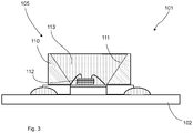
- Fig. 3 presents a simplified and magnified view of a LED light source 105 arranged on an elastic circuit board 102.
- the LED light source comprises a light-emitting diode 112 and surrounding it at least in the lateral direction a reflector body 110, comprising a reflector surface 111.
- the reflector body comprises a recess, the side walls of which form reflector surfaces.
- the light-emitting component 112 is disposed in the recess of the reflector body 110.
- the recess is filled at least partly with transparent protective material 113 such that the light-emitting diode 112 is at least partly inside the protective material.
- the protective material comprises a material that withstands light well, more particularly the light produced by the LED light source and/or UV light, and/or temperature without significantly darkening.
- the protective material 113 is, according to the invention, partly or wholly optical aliphatic thermoplastic polyurethane (aliphatic TPU).
- a lens 115 on top of the protective material 113 of the light-emitting diode 112 is a lens 115, which can be of the same material as or of different material to the protective material 113.
- the outer surface of the lens 115 can be treated with a protective material film 116, which is of aliphatic thermoplastic polyurethane, according to the invention.
- the lens 115 is of something else, e.g. of silicon.
- both the protective material 113 and the lens 115 can be of the aforementioned aliphatic thermoplastic polyurethane, in which case the protective material film 116 is not needed.
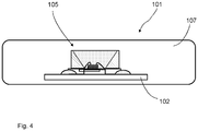
- Fig. 4 presents yet another embodiment, in which the LED band 101 of Fig. 3 is surrounded with an envelope part 107.
- the envelope part 107 is wholly or partly of aliphatic thermoplastic polyurethane, which keeps its clarity and transparency well, even though a photo effect, such as a UV light effect, and/or a thermal effect acts on it.
- an envelope part 107 formed from the material in question withstands mechanical loads well. The envelope part 107 thus functions partly or wholly as a protective material, the clarity of which and/or the transparency of which is retained well.
- optical aliphatic TPU aliphatic Thermoplastic Polyurethane
- This material has been used, or is used, e.g. as a thin film, inter alia, between the windshield glasses of vehicles or on the outer surface of glass in airplanes. This has been observed to possess very good UV durability.
- the material according to the invention is applied by extrusion onto the LED band, such as is described e.g. in publication WO9823896 A1 in connection with a conducting tape.
- Optical aliphatic thermoplastic polyurethane could be used, depending on the embodiment, directly on the surface of LEDs (encapsulation or potting), in the enclosure to replace silicon. In this case also an elastic structure and better mechanical properties are achieved.
- the material in question i.e. optical aliphatic thermoplastic polyurethane
- the protective material is clear aliphatic thermoplastic polyurethane, e.g. of the type Estane® ALR E87A. Also other suitable aliphatic TPU materials can be used.
- An elastic light-source band according to the invention can be manufactured in a continuous manufacturing process, such as with an extrusion process, roll-to-roll.
- the light-emitting diode 112 is more particularly a diode emitting blue or white light.
- the light source or light-source band are emergency exit luminaires, or are parts thereof, or control luminaires, guidance luminaires or signaling luminaires, or are parts thereof.
- the invention thus relates to a LED light source 105, which comprises at least one light-emitting component 112.
- the light-emitting component 112 is at least partly protected with a transparent protective material 113, which contains aliphatic thermoplastic polyurethane (TPU).
- TPU thermoplastic polyurethane
- the light-emitting component 112 is arranged in a recess, which is at least partly filled with protective material 113.
- the protective material is wholly aliphatic thermoplastic polyurethane (TPU).
- the protective material is partly aliphatic thermoplastic polyurethane (TPU).
- the protective material film 116 containing aliphatic thermoplastic polyurethane TPU is arranged on top of the light-emitting component 112 and/or the protective material 113 and/or the lens 115.
- the LED light source 105 is wholly protected with a transparent protective material, which contains aliphatic thermoplastic polyurethane (TPU).
- TPU thermoplastic polyurethane
- the light-emitting diode 112 is more particularly a diode emitting blue or white light.
- the invention also relates to a light-source band, which comprises light sources 105, such as LED light sources, arranged consecutively, which light-source band is surrounded at least partly with a transparent envelope 107.
- the light source 105, or at least the light-emitting component 112 of the light source is at least partly protected with a transparent protective material, which contains aliphatic thermoplastic polyurethane (TPU).
- TPU aliphatic thermoplastic polyurethane
- the LED light source 105 is wholly protected with a transparent envelope 107, which contains aliphatic thermoplastic polyurethane (TPU).
- TPU thermoplastic polyurethane
- the light-source band comprises light sources 105 according to any of claims 1 - 5.
- the envelope 107 is a flexible envelope.
Landscapes
- Engineering & Computer Science (AREA)
- General Engineering & Computer Science (AREA)
- Physics & Mathematics (AREA)
- Microelectronics & Electronic Packaging (AREA)
- Optics & Photonics (AREA)
- Led Device Packages (AREA)
- Illuminated Signs And Luminous Advertising (AREA)
- Materials For Medical Uses (AREA)
- Fastening Of Light Sources Or Lamp Holders (AREA)
- Non-Portable Lighting Devices Or Systems Thereof (AREA)
- Structures Or Materials For Encapsulating Or Coating Semiconductor Devices Or Solid State Devices (AREA)
Description
- The object of the invention is a light source as defined in the claims 1-5.
- The object of the invention is also a light-source band as defined in the claims 6 and 7. Prior art document
GB 2382868-A - Prior art document
US2008/0224159-A discloses the cross section of a radiation-emitting component wherein an LED is electrically contacted by a bond wire and a conductor band. The LED is situated in a reflector dish that exhibits a reflector surface and condenses the light emitted by the semiconductor component. The reflector dish and semiconductor component situated therein are enveloped by a potting comprising for example epoxy or silicone. The package is made of a radiation-crosslinked or chemically crosslinked thermoplastic that exhibits high reflectivity, from which reflector surfaces of the reflector dish are simultaneously shaped. - Prior art document
CN 201531785-U discloses a waterproof LED flexible light strip whereby the outer material can be a thermoplastic polyurethane (TPU). - The invention relates to light sources generally, more particularly to LED light sources. The invention also relates to light-source bands, which are used generally in control systems, guidance systems and warning systems.
- Light sources, e.g. LED light sources, are typically protected with various plastic materials, such as with silicon. It has been observed that the materials used nowadays, from which elasticity is also required, are sensitive to UV light and/or to heat. This often results in deterioration of the clarity and/or transparency of the protective material, sometimes very quickly, and at the same time in a deterioration in the luminescent capability of the light source. Often an undesired effect appears as a yellowing or as a stronger coloring of the protective material and as a deterioration in transparency.
- The drawback is typical e.g. in connection with LED light sources producing white or blue light, in the range of effect of which a darkening of the protective material and thus a deterioration in transparency have been observed.
- The drawback mainly appears in connection with LED light sources, the wavelength of which is short and mainly UV light, i.e. mainly with blue and white LEDs. The problem is thus the darkening of the protective plastic occurring from the combined effect of UV and heat, e.g. the heat produced by a LED light source. Another drawback is also the impurity that gains access to the surface of a LED light source via diffusion for the aforementioned reasons, which darkens the surface of the LED circuit.
- Earlier an epoxy resin type of protective agent was used in the protection inside the enclosure of a LED light source, but there has been a shift to the use of silicon resin in the high bright components available nowadays. This has been assumed to improve the lifetime of LED luminaires, but at the same time it has enabled detrimental characteristics, such as the diffusion of substances, when the temperature achieved by a light source is higher than in conventional LEDs of lower intensity. An obstacle to the use of epoxy in these cases has been exactly those same problems, the changing of the color of the protective material. Silicon, for its part, is also soft and does not give very good mechanical protection, and is not as such good protection against damp in demanding conditions.
- The drawbacks of prior art are substantial, e.g. in connection with LED light-source bands, which have as protection a flexible transparent protective envelope. LED light-source bands can be used e.g. in connection with various systems, such as for guiding people in situations of danger, such as in fire situations, to the emergency exits of buildings or vessels. These are various lightings for emergency exits. Known in the art are guidance lights, in which light sources are fixed consecutively into the shape of a band. The light sources of the band are arranged to light up in a situation of danger and to illuminate the emergency exit. Darkening of the plastic material functioning as protective material, however, impairs the brightness of the light sources, which is a great drawback e.g. in fire situations, in which visibility can otherwise be poor e.g. owing to the formation of smoke.
- The aim of the present invention is to achieve an entirely new type of solution for a LED luminaire, by means of which solution the drawbacks of prior art solutions are avoided. Another aim is to achieve a LED light-source band, the clarity and/or transparency of the protective material of which remain good.
- The light-source band according to the invention is characterized in that the light source, or at least the light-emitting component of the light source, is at least partly protected with a transparent protective material, which contains aliphatic thermoplastic polyurethane (TPU).
- The solution according to the invention has a number of important advantages. By protecting a LED light source or a light-producing diode with the protective material according to the invention a solution is achieved with which the drawbacks of prior-art solutions are avoided. The protective material remains clear and transparent despite the effect of light and/or the effect of heat. In this case the visibility of the light produced by the light sources remains as designed and no undesirable dimming occurs. When using optical aliphatic thermoplastic polyurethane (aliphatic TPU) as a protective material, the desired protective effect is achieved. In addition, the protective material also has other properties required in the use according to the object of the invention, in which case it is flexible and withstands mechanical wear well. Furthermore, the solution according to the invention is suited both as the protective material of individual light sources and as the envelope material of a light-source band. Furthermore the lens of a LED light source can be formed from the material, or it can be used as a film in connection with the lens or as a protective film in connection with a light source component. The protective material can thus be used directly on the surface of LEDs (encapsulation or potting), in the enclosure to replace silicon, in which case good elasticity and, with respect to silicon, better mechanical properties are achieved. The protective material can be used a protective coating on top of soldered components, forming an unbroken layer also on top of the silicon lenses of LED light sources. The light sources according to the invention can be used well e.g. in connection with high bright light sources, e.g. in connection with LED light-source bands, which have a flexible transparent protective envelope as protection. LED light-source bands according to the invention can be used e.g. in connection with various systems, such as for guiding people in situations of danger, such as in fire situations, to the emergency exits of buildings or vessels. These are various lightings for emergency exits. Known in the art are guidance lights, in which light sources are fixed consecutively into the shape of a band. The light sources of the band are arranged to light up in a situation of danger and to illuminate the emergency exit. The aliphatic thermoplastic polyurethane to be used as a protective material remains clear, in which case e.g. in fire situations the brightness of the light sources used for guidance of an emergency exit helps in finding the emergency exit although visibility is impaired owing to smoke formation.
- In the following, the invention will be described in more detail by the aid of an embodiment with reference to the attached drawings, wherein
-
Fig. 1 presents a top view of a light-source band according to the invention, -
Fig. 2 presents a cross-section of the light-source band according toFig. 1 , -
Fig. 3 presents a light source according to an embodiment of the invention, -
Fig. 4 presents a cross-section of a light-source band according to an embodiment of the invention, and -
Fig. 5 presents a light source according to a second embodiment of the invention. -
Fig. 1 presents a flat LED light-source band 101, which is used e.g. to guide the passage of people in various premises, e.g. at airports or in hospitals. It is typically approx. 20 mm in width and approx. 4 - 5 mm in thickness. It contains in the center a thinelastic circuit board 102, which consists of a band of an elastic plastic material and ofcopper wiring 103 made on the top of or on the bottom of said band e.g. by etching or by printing.LED light sources 105, and additionally also other components,e.g. resistors 106 for controlling and protecting the LED light sources, are connected to the top surface of the circuit board at regular intervals. TheLED light sources 105 can be monochromatic or polychromatic, and the desired guidance function can be obtained with them by controlling them to flash, to run, et cetera. According toFig. 2 , thecircuit board 102 and the components connected to it are surrounded with atransparent envelope part 107 of a plastic material around them such that preferably a fully waterproof LED light-source band, typically of e.g. protection class IP68, is obtained. -
Fig. 3 presents a simplified and magnified view of aLED light source 105 arranged on anelastic circuit board 102. The LED light source comprises a light-emittingdiode 112 and surrounding it at least in the lateral direction areflector body 110, comprising areflector surface 111. The reflector body comprises a recess, the side walls of which form reflector surfaces. The light-emittingcomponent 112 is disposed in the recess of thereflector body 110. The recess is filled at least partly with transparentprotective material 113 such that the light-emittingdiode 112 is at least partly inside the protective material. The protective material comprises a material that withstands light well, more particularly the light produced by the LED light source and/or UV light, and/or temperature without significantly darkening. Theprotective material 113 is, according to the invention, partly or wholly optical aliphatic thermoplastic polyurethane (aliphatic TPU). - According to
Fig. 5 on top of theprotective material 113 of the light-emittingdiode 112 is alens 115, which can be of the same material as or of different material to theprotective material 113. In one case the outer surface of thelens 115 can be treated with aprotective material film 116, which is of aliphatic thermoplastic polyurethane, according to the invention. In this case, it can be conceived that thelens 115 is of something else, e.g. of silicon. On the other hand, both theprotective material 113 and thelens 115 can be of the aforementioned aliphatic thermoplastic polyurethane, in which case theprotective material film 116 is not needed. -
Fig. 4 presents yet another embodiment, in which theLED band 101 ofFig. 3 is surrounded with anenvelope part 107. According to one embodiment theenvelope part 107 is wholly or partly of aliphatic thermoplastic polyurethane, which keeps its clarity and transparency well, even though a photo effect, such as a UV light effect, and/or a thermal effect acts on it. In addition, anenvelope part 107 formed from the material in question withstands mechanical loads well. Theenvelope part 107 thus functions partly or wholly as a protective material, the clarity of which and/or the transparency of which is retained well. - According to the invention optical aliphatic TPU (aliphatic Thermoplastic Polyurethane) is thus used, either partly or wholly, as a protective material. This material has been used, or is used, e.g. as a thin film, inter alia, between the windshield glasses of vehicles or on the outer surface of glass in airplanes. This has been observed to possess very good UV durability.
- According to one embodiment the material according to the invention is applied by extrusion onto the LED band, such as is described e.g. in publication
WO9823896 A1 - Optical aliphatic thermoplastic polyurethane (TPU) could be used, depending on the embodiment, directly on the surface of LEDs (encapsulation or potting), in the enclosure to replace silicon. In this case also an elastic structure and better mechanical properties are achieved.
- According to one embodiment the material in question, i.e. optical aliphatic thermoplastic polyurethane, could be a protective coating on top of soldered components, forming an unbroken layer also on top of silicon lenses.
- According to one embodiment the protective material is clear aliphatic thermoplastic polyurethane, e.g. of the type Estane® ALR E87A. Also other suitable aliphatic TPU materials can be used.
- An elastic light-source band according to the invention can be manufactured in a continuous manufacturing process, such as with an extrusion process, roll-to-roll.
- According to one embodiment the light-emitting
diode 112 is more particularly a diode emitting blue or white light. - According to one embodiment the light source or light-source band are emergency exit luminaires, or are parts thereof, or control luminaires, guidance luminaires or signaling luminaires, or are parts thereof.
- The invention thus relates to a
LED light source 105, which comprises at least one light-emittingcomponent 112. The light-emittingcomponent 112 is at least partly protected with a transparentprotective material 113, which contains aliphatic thermoplastic polyurethane (TPU). - According to one embodiment the light-emitting
component 112 is arranged in a recess, which is at least partly filled withprotective material 113. - According to one embodiment the protective material is wholly aliphatic thermoplastic polyurethane (TPU).
- According to one embodiment the protective material is partly aliphatic thermoplastic polyurethane (TPU).
- According to one embodiment the
protective material film 116 containing aliphatic thermoplastic polyurethane TPU is arranged on top of the light-emittingcomponent 112 and/or theprotective material 113 and/or thelens 115. - According to one embodiment the
LED light source 105 is wholly protected with a transparent protective material, which contains aliphatic thermoplastic polyurethane (TPU). - According to one embodiment the light-emitting
diode 112 is more particularly a diode emitting blue or white light. - The invention also relates to a light-source band, which comprises
light sources 105, such as LED light sources, arranged consecutively, which light-source band is surrounded at least partly with atransparent envelope 107. Thelight source 105, or at least the light-emittingcomponent 112 of the light source, is at least partly protected with a transparent protective material, which contains aliphatic thermoplastic polyurethane (TPU). - According to one embodiment the
LED light source 105 is wholly protected with atransparent envelope 107, which contains aliphatic thermoplastic polyurethane (TPU). - According to one embodiment the light-source band comprises
light sources 105 according to any of claims 1 - 5. - According to one embodiment the
envelope 107 is a flexible envelope. - It is obvious to the person skilled in the art that the invention is not limited to the embodiments presented above, but that it can be varied within the scope of the claims presented below. The characteristic features possibly presented in the description in conjunction with other characteristic features can also, if necessary, be used separately to each other.
Claims (7)
- LED light source (105), which comprises at least one light-emitting component (112), wherein the LED light source comprises:a reflector body (110) surrounding the light emitting component (112) at least in the lateral direction, which reflector body (110) comprises a reflector surface (111) and a recess, the side walls of which form reflector surfaces,wherein the light-emitting component (112) is disposed in the recess of the reflector body (110) and the recess is filled at least partly with transparent protective material (113) such that the light-emitting component (112) is at least partly inside the protective material,wherein the light-emitting component (112) is at least partly protected with a transparent protective material (113), which contains aliphatic thermoplastic polyurethane (TPU),wherein aliphatic thermoplastic polyurethane (TPU) is used directly on the surface of light-emitting component (112), andwherein the light-emitting component (112) is a diode emitting blue or white light.
- LED light source according to claim 1, characterized in that the protective material is wholly aliphatic thermoplastic polyurethane (TPU).
- LED light source according to claim 1 or 2, characterized in that the protective material is partly aliphatic thermoplastic polyurethane (TPU).
- LED light source according to any of claims 1 - 3, characterized in that the protective material film (116) containing aliphatic thermoplastic polyurethane (TPU) is arranged on top of the light-emitting component (112) and/or the protective material (113) and/or the lens (115).
- LED light source according to any of claims 1 - 4, characterized in that the LED light source (105) is wholly protected with a transparent protective material, which contains aliphatic thermoplastic polyurethane (TPU).
- Light-source band, which comprises light sources (105), such as LED light sources, arranged consecutively, which light-source band is surrounded at least partly with a transparent envelope (107), characterized in that
that the light-source band (101) comprises light sources (105) according to any of claims 1 - 5. - Light-source band according to claim 6, characterized in that the envelope (107) is a flexible envelope.
Applications Claiming Priority (2)
| Application Number | Priority Date | Filing Date | Title |
|---|---|---|---|
| FI20115139A FI122809B (en) | 2011-02-15 | 2011-02-15 | Light source and light source band |
| PCT/FI2012/050115 WO2012110695A1 (en) | 2011-02-15 | 2012-02-08 | Light source and light-source band |
Publications (3)
| Publication Number | Publication Date |
|---|---|
| EP2676525A1 EP2676525A1 (en) | 2013-12-25 |
| EP2676525A4 EP2676525A4 (en) | 2016-04-13 |
| EP2676525B1 true EP2676525B1 (en) | 2017-12-27 |
Family
ID=43629810
Family Applications (1)
| Application Number | Title | Priority Date | Filing Date |
|---|---|---|---|
| EP12746816.3A Active EP2676525B1 (en) | 2011-02-15 | 2012-02-08 | Light source and light-source band |
Country Status (12)
| Country | Link |
|---|---|
| US (1) | US9373763B2 (en) |
| EP (1) | EP2676525B1 (en) |
| JP (1) | JP2014506730A (en) |
| KR (1) | KR20140007434A (en) |
| CN (1) | CN103477708B (en) |
| AU (1) | AU2012216956B2 (en) |
| BR (1) | BR112013020786A2 (en) |
| CA (1) | CA2825418C (en) |
| FI (1) | FI122809B (en) |
| MX (1) | MX336241B (en) |
| RU (1) | RU2609150C2 (en) |
| WO (1) | WO2012110695A1 (en) |
Families Citing this family (5)
| Publication number | Priority date | Publication date | Assignee | Title |
|---|---|---|---|---|
| DE202013101820U1 (en) * | 2013-04-26 | 2013-06-03 | Edgar Burr | Shaft lighting device and elevator shaft with such a shaft lighting device |
| CN106322174A (en) * | 2015-06-24 | 2017-01-11 | 宏力照明集团有限公司 | High-performance LED photoelectric engine module |
| US11820890B2 (en) | 2021-04-01 | 2023-11-21 | Stratasys Inc | Pulverulent thermoplastic polymer blends |
| CN114096029A (en) * | 2021-10-15 | 2022-02-25 | 陈红 | TPU (thermoplastic polyurethane) -based flexible electroluminescent film and manufacturing process thereof |
| NL2030986B1 (en) * | 2022-02-17 | 2023-09-05 | Meldon Plastics B V | Holder for a light source |
Citations (2)
| Publication number | Priority date | Publication date | Assignee | Title |
|---|---|---|---|---|
| US20080224159A1 (en) * | 2005-04-26 | 2008-09-18 | Gertrud Krauter | Optical Element, Optoelectronic Component Comprising Said Element, and the Production Thereof |
| DE102007039416A1 (en) * | 2007-08-21 | 2009-02-26 | Airbus Deutschland Gmbh | Composite component with LEDs |
Family Cites Families (46)
| Publication number | Priority date | Publication date | Assignee | Title |
|---|---|---|---|---|
| EP1441395B9 (en) * | 1996-06-26 | 2012-08-15 | OSRAM Opto Semiconductors GmbH | Light-emitting semiconductor device with luminescence conversion element |
| FI108106B (en) * | 1996-11-25 | 2001-11-15 | Modular Technology Group Engin | Process for manufacturing conductor elements and conductor elements |
| US6274890B1 (en) * | 1997-01-15 | 2001-08-14 | Kabushiki Kaisha Toshiba | Semiconductor light emitting device and its manufacturing method |
| JP2000178340A (en) * | 1998-12-16 | 2000-06-27 | Mitsubishi Chemicals Corp | Manufacturing method of polyurethane-based thermoplastic elastomer |
| US6188527B1 (en) * | 1999-04-12 | 2001-02-13 | Hewlett-Packard Company | LED array PCB with adhesive rod lens |
| DE19918370B4 (en) * | 1999-04-22 | 2006-06-08 | Osram Opto Semiconductors Gmbh | LED white light source with lens |
| TW572925B (en) * | 2000-01-24 | 2004-01-21 | Mitsui Chemicals Inc | Urethane resin composition for sealing optoelectric conversion devices |
| KR100748815B1 (en) * | 2000-02-09 | 2007-08-13 | 니폰 라이츠 가부시키가이샤 | Light source device |
| JP4406490B2 (en) * | 2000-03-14 | 2010-01-27 | 株式会社朝日ラバー | Light emitting diode |
| DE10020163B4 (en) * | 2000-04-25 | 2007-05-31 | Bayer Materialscience Ag | Aliphatic thermoplastic polyurethanes and their use |
| JP2003060241A (en) * | 2001-08-10 | 2003-02-28 | Sony Corp | Circuit element arranging method and display device manufacturing method |
| EP1302988A3 (en) * | 2001-10-12 | 2007-01-24 | Bayer MaterialScience AG | Photovoltaic modules with a thermoplastic adhesive layer and method for fabricating the same |
| GB2382868B (en) * | 2001-12-05 | 2003-10-22 | Peter Norman Langmead | A method of operating a lighting strip |
| JP2004127988A (en) * | 2002-09-30 | 2004-04-22 | Toyoda Gosei Co Ltd | White light emitting device |
| WO2004070262A2 (en) * | 2003-02-04 | 2004-08-19 | Ilight Technologies, Inc. | Flexible illumination device for simulating neon lighting |
| US7038370B2 (en) * | 2003-03-17 | 2006-05-02 | Lumileds Lighting, U.S., Llc | Phosphor converted light emitting device |
| JP2005167091A (en) * | 2003-12-04 | 2005-06-23 | Nitto Denko Corp | Optical semiconductor device |
| KR100887489B1 (en) * | 2004-04-27 | 2009-03-10 | 파나소닉 주식회사 | Phosphor composition and method for producing the same, and light-emitting device using the same |
| KR100674831B1 (en) * | 2004-11-05 | 2007-01-25 | 삼성전기주식회사 | White light emitting diode package and its manufacturing method |
| TW200644746A (en) * | 2005-05-12 | 2006-12-16 | Matsushita Electric Industrial Co Ltd | Apparatus for forming phosphor layer and method for forming phosphor layer using the apparatus |
| US7682850B2 (en) * | 2006-03-17 | 2010-03-23 | Philips Lumileds Lighting Company, Llc | White LED for backlight with phosphor plates |
| US8158450B1 (en) * | 2006-05-05 | 2012-04-17 | Nanosolar, Inc. | Barrier films and high throughput manufacturing processes for photovoltaic devices |
| JP4830768B2 (en) * | 2006-05-10 | 2011-12-07 | 日亜化学工業株式会社 | Semiconductor light emitting device and method for manufacturing semiconductor light emitting device |
| US20120227901A1 (en) * | 2006-06-01 | 2012-09-13 | Ceralink, Inc. | Method of lamination using radio frequency heating and pressure |
| US8052303B2 (en) * | 2006-09-12 | 2011-11-08 | Huizhou Light Engine Ltd. | Integrally formed single piece light emitting diode light wire and uses thereof |
| US7889421B2 (en) * | 2006-11-17 | 2011-02-15 | Rensselaer Polytechnic Institute | High-power white LEDs and manufacturing method thereof |
| KR101327926B1 (en) | 2006-11-22 | 2013-11-13 | 루브리졸 어드밴스드 머티어리얼스, 인코포레이티드 | composition for modified transparence and highly elastic recovery of aliphatic based Thermoplastic polyurethane elastomer |
| US20100184938A1 (en) * | 2007-05-21 | 2010-07-22 | Lubrizol Advanced Materials, Inc. | Polyurethane Polymer |
| CN101075655B (en) * | 2007-06-05 | 2010-07-07 | 诸建平 | White surface light source lighting device |
| US20090065792A1 (en) * | 2007-09-07 | 2009-03-12 | 3M Innovative Properties Company | Method of making an led device having a dome lens |
| US8883528B2 (en) * | 2007-10-01 | 2014-11-11 | Intematix Corporation | Methods of producing light emitting device with phosphor wavelength conversion |
| CN101418927A (en) * | 2007-10-24 | 2009-04-29 | 富士迈半导体精密工业(上海)有限公司 | Light source assembly |
| JP2010074117A (en) * | 2007-12-07 | 2010-04-02 | Panasonic Electric Works Co Ltd | Light emitting device |
| JP5631745B2 (en) * | 2008-02-21 | 2014-11-26 | 日東電工株式会社 | Light emitting device having translucent ceramic plate |
| KR101046079B1 (en) * | 2008-04-03 | 2011-07-01 | 삼성엘이디 주식회사 | LED element and LED luminaire using the same |
| DE102008025398B4 (en) * | 2008-05-28 | 2018-04-26 | Osram Gmbh | Protective cladding for a LED band |
| CN201297535Y (en) * | 2008-11-14 | 2009-08-26 | 江苏稳润光电有限公司 | LED flexible combined waterproof lamp strip |
| ES2691403T3 (en) * | 2008-12-29 | 2018-11-27 | Basf Se | Thermoplastic polyurethane light conductor |
| US8328406B2 (en) * | 2009-05-13 | 2012-12-11 | Oree, Inc. | Low-profile illumination device |
| CN201531785U (en) * | 2009-05-31 | 2010-07-21 | 上海宜美电子科技有限公司 | Flexible LED strip |
| US9048404B2 (en) * | 2009-07-06 | 2015-06-02 | Zhuo Sun | Thin flat solid state light source module |
| JP5342368B2 (en) * | 2009-08-06 | 2013-11-13 | 株式会社朝日ラバー | Light emitting diode |
| WO2011035483A1 (en) * | 2009-09-25 | 2011-03-31 | 海洋王照明科技股份有限公司 | Semiconductor light-emitting device and encapsulating method thereof |
| EP2512801B1 (en) * | 2009-12-17 | 2014-05-14 | Dow Global Technologies LLC | Composite laminates and uses thereof |
| JP5749327B2 (en) * | 2010-03-19 | 2015-07-15 | 日東電工株式会社 | Garnet phosphor ceramic sheet for light emitting devices |
| JP2012015254A (en) * | 2010-06-30 | 2012-01-19 | Nitto Denko Corp | Phosphor ceramic and light emitting device |
-
2011
- 2011-02-15 FI FI20115139A patent/FI122809B/en active IP Right Grant
-
2012
- 2012-02-08 RU RU2013142142A patent/RU2609150C2/en active
- 2012-02-08 WO PCT/FI2012/050115 patent/WO2012110695A1/en not_active Ceased
- 2012-02-08 MX MX2013008817A patent/MX336241B/en unknown
- 2012-02-08 US US13/985,444 patent/US9373763B2/en active Active
- 2012-02-08 AU AU2012216956A patent/AU2012216956B2/en not_active Ceased
- 2012-02-08 JP JP2013552994A patent/JP2014506730A/en active Pending
- 2012-02-08 CN CN201280009125.XA patent/CN103477708B/en active Active
- 2012-02-08 BR BR112013020786A patent/BR112013020786A2/en not_active IP Right Cessation
- 2012-02-08 EP EP12746816.3A patent/EP2676525B1/en active Active
- 2012-02-08 KR KR1020137024245A patent/KR20140007434A/en not_active Ceased
- 2012-02-08 CA CA2825418A patent/CA2825418C/en not_active Expired - Fee Related
Patent Citations (2)
| Publication number | Priority date | Publication date | Assignee | Title |
|---|---|---|---|---|
| US20080224159A1 (en) * | 2005-04-26 | 2008-09-18 | Gertrud Krauter | Optical Element, Optoelectronic Component Comprising Said Element, and the Production Thereof |
| DE102007039416A1 (en) * | 2007-08-21 | 2009-02-26 | Airbus Deutschland Gmbh | Composite component with LEDs |
Also Published As
| Publication number | Publication date |
|---|---|
| FI20115139A0 (en) | 2011-02-15 |
| KR20140007434A (en) | 2014-01-17 |
| WO2012110695A1 (en) | 2012-08-23 |
| CN103477708A (en) | 2013-12-25 |
| JP2014506730A (en) | 2014-03-17 |
| EP2676525A1 (en) | 2013-12-25 |
| BR112013020786A2 (en) | 2016-10-18 |
| CA2825418C (en) | 2019-12-03 |
| CN103477708B (en) | 2016-08-24 |
| RU2013142142A (en) | 2015-03-27 |
| US20130320366A1 (en) | 2013-12-05 |
| CA2825418A1 (en) | 2012-08-23 |
| MX336241B (en) | 2016-01-13 |
| MX2013008817A (en) | 2013-12-16 |
| FI122809B (en) | 2012-07-13 |
| US9373763B2 (en) | 2016-06-21 |
| AU2012216956B2 (en) | 2015-10-29 |
| RU2609150C2 (en) | 2017-01-30 |
| EP2676525A4 (en) | 2016-04-13 |
| AU2012216956A1 (en) | 2013-08-22 |
Similar Documents
| Publication | Publication Date | Title |
|---|---|---|
| US12624810B2 (en) | Lighting device | |
| US8177391B2 (en) | Tube-type or channel-type LED lighting apparatus | |
| CN112219060A (en) | Lighting module and lighting device with same | |
| EP3542400B1 (en) | Lighting device with uv led | |
| GB2480216A (en) | Led module for modified lamps and modified led lamp | |
| US9022607B2 (en) | Leadframe-based surface mount technology segmented display design and method of manufacture | |
| CA2825418C (en) | Light source and light-source band | |
| US12359780B2 (en) | Lighting module, lighting device and lamp | |
| KR102173117B1 (en) | Lamp unit for vechile | |
| JP7844684B2 (en) | Lighting modules, lighting fixtures, and lamps | |
| CN111602001B (en) | Lighting module and lighting device with same | |
| KR20200126290A (en) | Lighting module and lighting apparatus | |
| JP7569340B2 (en) | Illumination module, illumination device and lamp | |
| HK1192098B (en) | Light source and light-source band | |
| HK1192098A (en) | Light source and light-source band | |
| KR102672280B1 (en) | Lighting apparatus | |
| KR102288767B1 (en) | Lighting module and lighting apparatus | |
| KR101977718B1 (en) | Illuminating device | |
| KR20220046090A (en) | Lighting apparatus and lamp including the same |
Legal Events
| Date | Code | Title | Description |
|---|---|---|---|
| PUAI | Public reference made under article 153(3) epc to a published international application that has entered the european phase |
Free format text: ORIGINAL CODE: 0009012 |
|
| 17P | Request for examination filed |
Effective date: 20130813 |
|
| AK | Designated contracting states |
Kind code of ref document: A1 Designated state(s): AL AT BE BG CH CY CZ DE DK EE ES FI FR GB GR HR HU IE IS IT LI LT LU LV MC MK MT NL NO PL PT RO RS SE SI SK SM TR |
|
| DAX | Request for extension of the european patent (deleted) | ||
| RA4 | Supplementary search report drawn up and despatched (corrected) |
Effective date: 20160310 |
|
| RIC1 | Information provided on ipc code assigned before grant |
Ipc: H01L 33/56 20100101ALN20160304BHEP Ipc: F21S 4/00 20160101ALI20160304BHEP Ipc: H01L 33/00 20100101ALI20160304BHEP Ipc: F21Y 103/00 20160101ALI20160304BHEP Ipc: F21K 99/00 20160101ALI20160304BHEP Ipc: F21S 4/22 20160101ALI20160304BHEP Ipc: H01L 33/58 20100101ALN20160304BHEP Ipc: H05B 33/04 20060101AFI20160304BHEP Ipc: F21V 31/00 20060101ALI20160304BHEP Ipc: H01L 25/075 20060101ALN20160304BHEP |
|
| 17Q | First examination report despatched |
Effective date: 20170102 |
|
| GRAP | Despatch of communication of intention to grant a patent |
Free format text: ORIGINAL CODE: EPIDOSNIGR1 |
|
| RIC1 | Information provided on ipc code assigned before grant |
Ipc: H01L 33/58 20100101ALN20170706BHEP Ipc: F21S 4/00 20160101ALI20170706BHEP Ipc: F21S 4/22 20160101ALI20170706BHEP Ipc: F21Y 103/00 20160101ALI20170706BHEP Ipc: F21K 99/00 20160101ALI20170706BHEP Ipc: F21Y 103/10 20160101ALN20170706BHEP Ipc: H01L 33/00 20100101ALI20170706BHEP Ipc: F21V 31/00 20060101ALI20170706BHEP Ipc: H01L 33/56 20100101ALN20170706BHEP Ipc: H05B 33/04 20060101AFI20170706BHEP Ipc: H01L 25/075 20060101ALN20170706BHEP Ipc: F21Y 115/10 20160101ALN20170706BHEP |
|
| INTG | Intention to grant announced |
Effective date: 20170718 |
|
| GRAS | Grant fee paid |
Free format text: ORIGINAL CODE: EPIDOSNIGR3 |
|
| GRAA | (expected) grant |
Free format text: ORIGINAL CODE: 0009210 |
|
| AK | Designated contracting states |
Kind code of ref document: B1 Designated state(s): AL AT BE BG CH CY CZ DE DK EE ES FI FR GB GR HR HU IE IS IT LI LT LU LV MC MK MT NL NO PL PT RO RS SE SI SK SM TR |
|
| REG | Reference to a national code |
Ref country code: GB Ref legal event code: FG4D |
|
| REG | Reference to a national code |
Ref country code: CH Ref legal event code: EP |
|
| REG | Reference to a national code |
Ref country code: AT Ref legal event code: REF Ref document number: 959368 Country of ref document: AT Kind code of ref document: T Effective date: 20180115 |
|
| REG | Reference to a national code |
Ref country code: IE Ref legal event code: FG4D |
|
| REG | Reference to a national code |
Ref country code: DE Ref legal event code: R096 Ref document number: 602012041364 Country of ref document: DE |
|
| REG | Reference to a national code |
Ref country code: FR Ref legal event code: PLFP Year of fee payment: 7 |
|
| REG | Reference to a national code |
Ref country code: SE Ref legal event code: TRGR |
|
| PG25 | Lapsed in a contracting state [announced via postgrant information from national office to epo] |
Ref country code: LT Free format text: LAPSE BECAUSE OF FAILURE TO SUBMIT A TRANSLATION OF THE DESCRIPTION OR TO PAY THE FEE WITHIN THE PRESCRIBED TIME-LIMIT Effective date: 20171227 Ref country code: FI Free format text: LAPSE BECAUSE OF FAILURE TO SUBMIT A TRANSLATION OF THE DESCRIPTION OR TO PAY THE FEE WITHIN THE PRESCRIBED TIME-LIMIT Effective date: 20171227 Ref country code: NO Free format text: LAPSE BECAUSE OF FAILURE TO SUBMIT A TRANSLATION OF THE DESCRIPTION OR TO PAY THE FEE WITHIN THE PRESCRIBED TIME-LIMIT Effective date: 20180327 |
|
| REG | Reference to a national code |
Ref country code: NL Ref legal event code: MP Effective date: 20171227 |
|
| REG | Reference to a national code |
Ref country code: LT Ref legal event code: MG4D |
|
| PG25 | Lapsed in a contracting state [announced via postgrant information from national office to epo] |
Ref country code: RS Free format text: LAPSE BECAUSE OF FAILURE TO SUBMIT A TRANSLATION OF THE DESCRIPTION OR TO PAY THE FEE WITHIN THE PRESCRIBED TIME-LIMIT Effective date: 20171227 Ref country code: GR Free format text: LAPSE BECAUSE OF FAILURE TO SUBMIT A TRANSLATION OF THE DESCRIPTION OR TO PAY THE FEE WITHIN THE PRESCRIBED TIME-LIMIT Effective date: 20180328 Ref country code: HR Free format text: LAPSE BECAUSE OF FAILURE TO SUBMIT A TRANSLATION OF THE DESCRIPTION OR TO PAY THE FEE WITHIN THE PRESCRIBED TIME-LIMIT Effective date: 20171227 Ref country code: LV Free format text: LAPSE BECAUSE OF FAILURE TO SUBMIT A TRANSLATION OF THE DESCRIPTION OR TO PAY THE FEE WITHIN THE PRESCRIBED TIME-LIMIT Effective date: 20171227 Ref country code: BG Free format text: LAPSE BECAUSE OF FAILURE TO SUBMIT A TRANSLATION OF THE DESCRIPTION OR TO PAY THE FEE WITHIN THE PRESCRIBED TIME-LIMIT Effective date: 20180327 |
|
| PG25 | Lapsed in a contracting state [announced via postgrant information from national office to epo] |
Ref country code: NL Free format text: LAPSE BECAUSE OF FAILURE TO SUBMIT A TRANSLATION OF THE DESCRIPTION OR TO PAY THE FEE WITHIN THE PRESCRIBED TIME-LIMIT Effective date: 20171227 |
|
| PG25 | Lapsed in a contracting state [announced via postgrant information from national office to epo] |
Ref country code: ES Free format text: LAPSE BECAUSE OF FAILURE TO SUBMIT A TRANSLATION OF THE DESCRIPTION OR TO PAY THE FEE WITHIN THE PRESCRIBED TIME-LIMIT Effective date: 20171227 Ref country code: CZ Free format text: LAPSE BECAUSE OF FAILURE TO SUBMIT A TRANSLATION OF THE DESCRIPTION OR TO PAY THE FEE WITHIN THE PRESCRIBED TIME-LIMIT Effective date: 20171227 Ref country code: CY Free format text: LAPSE BECAUSE OF FAILURE TO SUBMIT A TRANSLATION OF THE DESCRIPTION OR TO PAY THE FEE WITHIN THE PRESCRIBED TIME-LIMIT Effective date: 20171227 Ref country code: EE Free format text: LAPSE BECAUSE OF FAILURE TO SUBMIT A TRANSLATION OF THE DESCRIPTION OR TO PAY THE FEE WITHIN THE PRESCRIBED TIME-LIMIT Effective date: 20171227 Ref country code: SK Free format text: LAPSE BECAUSE OF FAILURE TO SUBMIT A TRANSLATION OF THE DESCRIPTION OR TO PAY THE FEE WITHIN THE PRESCRIBED TIME-LIMIT Effective date: 20171227 |
|
| PG25 | Lapsed in a contracting state [announced via postgrant information from national office to epo] |
Ref country code: RO Free format text: LAPSE BECAUSE OF FAILURE TO SUBMIT A TRANSLATION OF THE DESCRIPTION OR TO PAY THE FEE WITHIN THE PRESCRIBED TIME-LIMIT Effective date: 20171227 Ref country code: SM Free format text: LAPSE BECAUSE OF FAILURE TO SUBMIT A TRANSLATION OF THE DESCRIPTION OR TO PAY THE FEE WITHIN THE PRESCRIBED TIME-LIMIT Effective date: 20171227 Ref country code: PL Free format text: LAPSE BECAUSE OF FAILURE TO SUBMIT A TRANSLATION OF THE DESCRIPTION OR TO PAY THE FEE WITHIN THE PRESCRIBED TIME-LIMIT Effective date: 20171227 Ref country code: IS Free format text: LAPSE BECAUSE OF FAILURE TO SUBMIT A TRANSLATION OF THE DESCRIPTION OR TO PAY THE FEE WITHIN THE PRESCRIBED TIME-LIMIT Effective date: 20180427 |
|
| PG25 | Lapsed in a contracting state [announced via postgrant information from national office to epo] |
Ref country code: MC Free format text: LAPSE BECAUSE OF FAILURE TO SUBMIT A TRANSLATION OF THE DESCRIPTION OR TO PAY THE FEE WITHIN THE PRESCRIBED TIME-LIMIT Effective date: 20171227 |
|
| REG | Reference to a national code |
Ref country code: DE Ref legal event code: R097 Ref document number: 602012041364 Country of ref document: DE |
|
| PLBE | No opposition filed within time limit |
Free format text: ORIGINAL CODE: 0009261 |
|
| STAA | Information on the status of an ep patent application or granted ep patent |
Free format text: STATUS: NO OPPOSITION FILED WITHIN TIME LIMIT |
|
| REG | Reference to a national code |
Ref country code: IE Ref legal event code: MM4A |
|
| REG | Reference to a national code |
Ref country code: BE Ref legal event code: MM Effective date: 20180228 |
|
| PG25 | Lapsed in a contracting state [announced via postgrant information from national office to epo] |
Ref country code: LU Free format text: LAPSE BECAUSE OF NON-PAYMENT OF DUE FEES Effective date: 20180208 Ref country code: DK Free format text: LAPSE BECAUSE OF FAILURE TO SUBMIT A TRANSLATION OF THE DESCRIPTION OR TO PAY THE FEE WITHIN THE PRESCRIBED TIME-LIMIT Effective date: 20171227 |
|
| 26N | No opposition filed |
Effective date: 20180928 |
|
| PG25 | Lapsed in a contracting state [announced via postgrant information from national office to epo] |
Ref country code: IE Free format text: LAPSE BECAUSE OF NON-PAYMENT OF DUE FEES Effective date: 20180208 |
|
| PG25 | Lapsed in a contracting state [announced via postgrant information from national office to epo] |
Ref country code: SI Free format text: LAPSE BECAUSE OF FAILURE TO SUBMIT A TRANSLATION OF THE DESCRIPTION OR TO PAY THE FEE WITHIN THE PRESCRIBED TIME-LIMIT Effective date: 20171227 Ref country code: BE Free format text: LAPSE BECAUSE OF NON-PAYMENT OF DUE FEES Effective date: 20180228 |
|
| PG25 | Lapsed in a contracting state [announced via postgrant information from national office to epo] |
Ref country code: MT Free format text: LAPSE BECAUSE OF NON-PAYMENT OF DUE FEES Effective date: 20180208 |
|
| PG25 | Lapsed in a contracting state [announced via postgrant information from national office to epo] |
Ref country code: TR Free format text: LAPSE BECAUSE OF FAILURE TO SUBMIT A TRANSLATION OF THE DESCRIPTION OR TO PAY THE FEE WITHIN THE PRESCRIBED TIME-LIMIT Effective date: 20171227 |
|
| PGFP | Annual fee paid to national office [announced via postgrant information from national office to epo] |
Ref country code: SE Payment date: 20200220 Year of fee payment: 9 Ref country code: AT Payment date: 20200220 Year of fee payment: 9 |
|
| PG25 | Lapsed in a contracting state [announced via postgrant information from national office to epo] |
Ref country code: HU Free format text: LAPSE BECAUSE OF FAILURE TO SUBMIT A TRANSLATION OF THE DESCRIPTION OR TO PAY THE FEE WITHIN THE PRESCRIBED TIME-LIMIT; INVALID AB INITIO Effective date: 20120208 Ref country code: PT Free format text: LAPSE BECAUSE OF FAILURE TO SUBMIT A TRANSLATION OF THE DESCRIPTION OR TO PAY THE FEE WITHIN THE PRESCRIBED TIME-LIMIT Effective date: 20171227 |
|
| PGFP | Annual fee paid to national office [announced via postgrant information from national office to epo] |
Ref country code: CH Payment date: 20200219 Year of fee payment: 9 |
|
| REG | Reference to a national code |
Ref country code: AT Ref legal event code: UEP Ref document number: 959368 Country of ref document: AT Kind code of ref document: T Effective date: 20171227 |
|
| PG25 | Lapsed in a contracting state [announced via postgrant information from national office to epo] |
Ref country code: MK Free format text: LAPSE BECAUSE OF NON-PAYMENT OF DUE FEES Effective date: 20171227 |
|
| PG25 | Lapsed in a contracting state [announced via postgrant information from national office to epo] |
Ref country code: AL Free format text: LAPSE BECAUSE OF FAILURE TO SUBMIT A TRANSLATION OF THE DESCRIPTION OR TO PAY THE FEE WITHIN THE PRESCRIBED TIME-LIMIT Effective date: 20171227 |
|
| REG | Reference to a national code |
Ref country code: SE Ref legal event code: EUG |
|
| REG | Reference to a national code |
Ref country code: AT Ref legal event code: MM01 Ref document number: 959368 Country of ref document: AT Kind code of ref document: T Effective date: 20210208 |
|
| PG25 | Lapsed in a contracting state [announced via postgrant information from national office to epo] |
Ref country code: LI Free format text: LAPSE BECAUSE OF NON-PAYMENT OF DUE FEES Effective date: 20210228 Ref country code: CH Free format text: LAPSE BECAUSE OF NON-PAYMENT OF DUE FEES Effective date: 20210228 Ref country code: AT Free format text: LAPSE BECAUSE OF NON-PAYMENT OF DUE FEES Effective date: 20210208 |
|
| PG25 | Lapsed in a contracting state [announced via postgrant information from national office to epo] |
Ref country code: SE Free format text: LAPSE BECAUSE OF NON-PAYMENT OF DUE FEES Effective date: 20210209 |
|
| P01 | Opt-out of the competence of the unified patent court (upc) registered |
Effective date: 20230614 |
|
| PGFP | Annual fee paid to national office [announced via postgrant information from national office to epo] |
Ref country code: GB Payment date: 20260219 Year of fee payment: 15 |
|
| PGFP | Annual fee paid to national office [announced via postgrant information from national office to epo] |
Ref country code: DE Payment date: 20260218 Year of fee payment: 15 |
|
| PGFP | Annual fee paid to national office [announced via postgrant information from national office to epo] |
Ref country code: IT Payment date: 20260224 Year of fee payment: 15 |
|
| PGFP | Annual fee paid to national office [announced via postgrant information from national office to epo] |
Ref country code: FR Payment date: 20260218 Year of fee payment: 15 |